
 Open Access Article
 This Open Access Article is licensed under a
 Creative Commons Attribution 3.0 Unported Licence
Discrete modeling of ionic space charge zones in solids†
Chuanlian
Xiao
 ,
Chia-Chin
Chen‡
and
Joachim
Maier
*
,
Chia-Chin
Chen‡
and
Joachim
Maier
*
Max Planck Institute for Solid State Research, Heisenbergstraße 1, 70569 Stuttgart, Germany. E-mail: office-maier@fkf.mpg.de
First published on 6th April 2022
Abstract
The discrete model of space charge zones in solids reveals and remedies a variety of problems with the classic continuous Gouy–Chapman solution that occur for pronounced space charge potentials. Besides inherent problems of internal consistency, it is essentially the extremely steep profile close to the interface which makes this continuum approach questionable. Not only is quasi-1D discrete modeling a sensible approach for large space charge effects, it can also favorably be combined with the continuum description. A particularly useful application is the explicit implementation of crystallographic details and non-idealities close to the interface. This enables us to consider elastic, structural or saturation effects as well as permittivity variations in a simple but realistic way. We address details of the charge carrier profiles, but also overall properties such as space charge capacitance and space charge resistance. In the latter case the difference in the total charge (at identical concentration) is of importance, in the first case it is the inherent difference in the centroid of charge (at identical total charge) that is remarkable. The model is equally applicable for ionic charge carriers and small polarons.
Introduction
Space charge situations are ubiquitous. Whenever interfaces in charge-carrier containing systems are involved, electroneutrality is broken and individual charge carrier redistribution, be it electronic or be it ionic, occurs (at the cost of and balanced by a back-driving electric field).This does not only hold for rather classic systems in the field of semiconductors1 or liquid state electrochemistry.2 It has also been shown to be of great relevance for solid state ionics in the context of solid electrolytes (interfaces with electrodes;3 grain boundaries,4 composite electrolytes5) or of mixed conductors, used for storage,6 sensing,7 catalysis8 and many other purposes. In the case of storage electrodes, one deals with grain boundaries, contacts to electrolyte or the respective passivation layers and contacts with current collectors.9 Space charge effects can not only explain various interfacial phenomena, they can also be used to generate beneficial effects. Such effects can refer to resistive, but also storage anomalies.5,9
Of great help in this context is the generalized thermodynamic contact picture (Fig. 1) which takes account of both ionic and electronic redistribution and their coupling via the chemical potential of components (mirrored by, e.g., oxygen partial pressure over oxides;10 Li-activity in battery electrodes,11etc.).
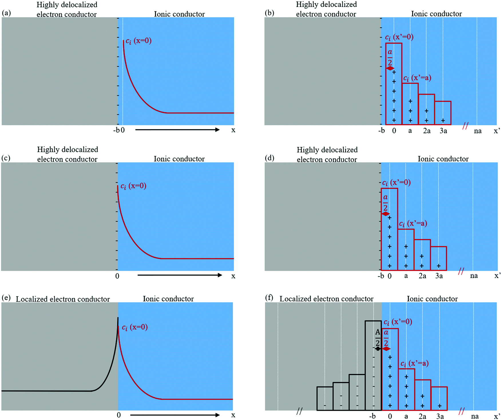 | ||
| Fig. 1 Sketch of (a), (c) and (e) continuous model and (b), (d) and (f) discrete model. (a)–(d) Contact between a highly delocalized electron conductor and an ionic conductor; (e) and (f) contact between a localized electron conductor and an ionic conductor. Note the different coordinates x and x′ denoting the zero-points in the continuous and in the discrete model, respectively. b is the distance between the two adjacent discretely charged layers, its minimum value is a/2 in the case of delocalized electron conductor and (a + A)/2 in the case of localized electron conductor where a, A refer to the atomic size in the ionic conductor and localized electron conductor, respectively. | ||
In the case of full equilibrium, the combination of Poisson's equation and Boltzmann-distribution leads – in the continuum picture – to Gouy–Chapman (GC) profiles12 (while depletion of mobile majority carriers in doped systems leads to Mott–Schottky profiles13). In particular, in the first case the profiles can be very steep if the interfacial effects are pronounced. Very often the majority of the charge decays within a distance that is on the order of the interatomic spacing reflecting the overstretching of the continuum approach. That there is no simple match between reality and continuum model is shown by the fact that in the latter the total charge stored in the space charge layer (Q) is proportional to the square root of the concentration of the outmost position (x = 0 in Fig. 1a) rather than to the concentration in the outmost layer (x′ = 0 in Fig. 1b). Discrepancies are obvious not only for space charge conduction14 but also for space charge storage.12Fig. 2 gives a striking example in the case of interfacial storage, where the power law between the amount of stored charge and the activity of the component fails qualitatively in the continuum picture in contrast to discrete modeling.12
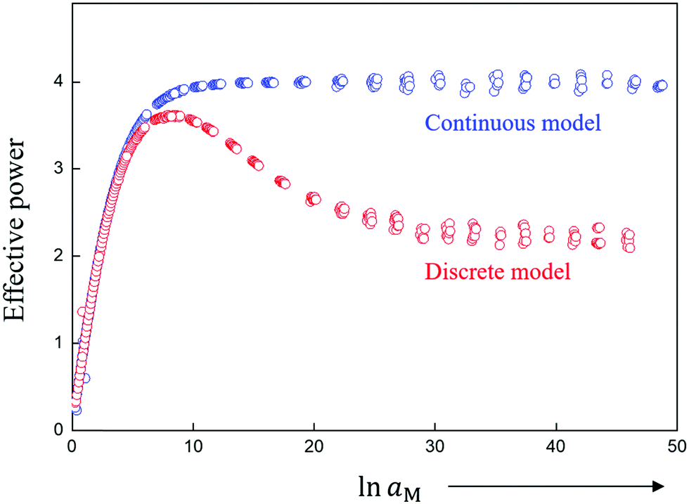 | ||
| Fig. 2 Comparison of continuous and discrete model for dissociative storage of the component M (e.g. Li, Na) (for conditions discussed in ref. 12). While the continuous model predicts for large storage a power law between M-activity (reflected e.g. by the cell voltage) and stored amount with the exponent 4, the discrete model predicts the correct value of 2 corresponding to the fact that for large storage essentially the first layer is responsible. | ||
It is also well-known from liquid electrochemistry that the calculated space charge capacitance differs greatly from the measured one and needs to be corrected by a rigid capacitance contribution that more or less is based on the finite atomic spacing of charge and counter charge (Fig. 1a) (see e.g. ref. 2).
In solid state ionics essentially two chief scenarios have been treated: (i) ion redistribution at constant composition as occurring in heterogeneous electrolytes such as LiI:Al2O3 composites15 or CaF2–BaF2 heterolayers,16 and (ii) the occurrence of ionic space charges compensated by electronic ones in the case of job-sharing storage relying on compositional variations.12 The most general case considers redistribution of ions and electrons in both phases in contact. Selected literature examples are LiF/TiO2,3 SrTiO3-grain boundaries,10 TiO2-dislocations,17 RbAg4I5/C.18
Here the dissociative storage of metal components such as Li, Na or Ag at the contact of an ion conductor with a metallic electron conductor is chosen as a master example (similar to the classically discussed electrolyte/electrode interfaces), and the space charge profiles are modeled by discrete quasi 1D simulations. This battery-related example has the advantage that it also includes the chemical potential of the respective component as parameter. Equivalently one can consider oxygen ion depletion or accumulation at a perovskite interface as a function of position with the oxygen partial pressure as parameter. As far as the modeling technique is concerned we follow the important work of Armstrong and Horrocks.19 We think that 1D simulation (discretization perpendicular to the interface) captures the major points while discretization in two or three dimensions would only reveal additional insight into other questions such as crystallographic matching or image force effects, that are, though important, beyond the interest of the present paper. As in the continuum Poisson–Boltzmann equation we use a coarse-grained electric potential in order to be independent on quantum-mechanical details.20
We also intend to show that substantial progress in the field of space charge theory is expected to come from such discretization, rather than from introducing corrections into the overstrained Gouy–Chapman function.21–28 While the difference between continuum and discrete approach is small for small space charge potentials (small means small with respect to RT/F), the full value is revealed at high electric potential drops between the two origins in Fig. 1a as typically occurring in supercapacitors (cf. also Fig. 2).
Because of the extreme worth of the continuum approach in view of its simplicity, the approach is also considered useful for developing corrections (based on the discretization) that help Gouy–Chapman considerations to be still applicable, as well as to develop criteria that decide on when they fail.
The structure of the paper is as follows: first, the numerical procedure is set out. Second, effects on capacitance and resistance are described whereby special emphasis is laid on the small-signal evaluation. Though this is not the most typical case where the continuum approach fails, it is extremely helpful for the illustration as the analysis is straightforward. Third, it is shown how by using realistic input data, e.g. from DFT, corrections to the idealized assumptions (constant structure, constant dielectric constant, no site saturation) can be implemented and even advantageously combined with the continuum description for the flatter part of the profiles.
To avoid misunderstandings we stress again that it is neither the objective of the paper to go beyond the usual assumptions underlying the Poisson–Boltzmann equation (except discretization), nor do we intend to analyze experimental results. This may be subject of future work.
Procedure
Here we accept the Poisson–Boltzmann equation as relevant continuum description and do not analyze its intrinsic weaknesses. Short-comings such as finite-size effects are discussed in the literature.29–31 A fundamental weakness is based on identifying the potential of mean force (which includes interaction of the ion under concern with the matrix) as appearing in the Boltzmann distribution, with the mean potential (where such effects are ignored) as appearing in Poisson's equation; this problem has also been brought in connection with the violation of the superposition principle in the Poisson–Boltzmann equation (see supplementary for more details as well as ref. 1, 9 and 10 in ESI†).The electric potential ϕ in a medium is, according to Poisson's equation, referred to the effective charge density ρ as well as the corresponding dielectric constant ε
 | (1) |
If the charge carrier concentration is described by a Boltzmann distribution (the local concentration proportional to the bulk concentration cm∞ and the exponential of the electric potential difference with respect to the bulk value ϕ∞) and by identifying this potential with the one in Poisson's equation (cf. ESI†) we obtain the well-known Poisson–Boltzmann equation
 | (2) |
 | (3) |
In discretized form eqn (3) reads
 | (4) |
 is the Debye length.
Fig. 3 shows two key features of the discrete model:19 first, as charge carriers are strictly located on lattice planes, ∇ϕ (slope in Fig. 3a, i.e. electric field) only changes its value on each plane and remains invariant in between the planes. (See Poisson's equation, ∇2ϕ ∝ ρ. If ρ = 0, ∇ϕ is constant.) Such a feature is different from the continuous model in which ∇ϕ varies continuously because ρ is thought to be nonzero within the whole space charge region. Second, as suggested in eqn (4), the slope between plane j and j − 1 is proportional to the stored charge summing up from plane j to the bulk, and hence increases when the interface is approached (Fig. 3a). Fig. 3b shows the situation in terms of charge: While in the discrete case one can assign a charge to a specific layer (Fig. 3b), in the continuous approach one has to be aware of smearing the charge density out by  around the position in which the atoms sit which are vertically separated by a. This is the reason why we have to distinguish between x and x′ as defined in Fig. 1. The rationale as to why the continuous profile best starts at
  (and hence
  ) is given below.
 | ||
| Fig. 3 Sketch of (a) potential profile, (b) charge distribution in discrete model (contact between a highly delocalized electron conductor and an ionic conductor). The negative counter charge concentrates on the very surface of the highly delocalized electron conductor. | ||
Results
Idealized model
Fig. 1b, d and f sketches the discrete charge distribution of a contact between an electron conductor and a solid ion conductor. It considers two extreme situations. In the highly delocalized electron conductor we assume that the electronic counter charge concentrates on the very surface of the electron conductor (Fig. 1a–d); in the second case we consider (Fig. 1e and f) the contact of a localized electron conductor and an ion conductor where both types of charges are strictly localized. In both cases, the charges are separated forming an electric double layer. If b is the distance between the two adjacent discretely charged layers, its minimum value is in the first and (a + A)/2 in the second case where A is the atomic size in the localized electron conductor. Thus, it is pertinent to distinguish between the extreme cases of a highly delocalized electron conductor and an electron conductor where the electrons are localized at the polyvalent cations. For the sake of simplicity the fact is ignored that according to the jellium model the electron density on a metal can be smeared out around the very surface with an extent of a fraction of the Fermi-wavelength (typ. by ∼2 Å).32 In the following the discrete charge distribution is calculated, compared with solutions from the Poisson–Boltzmann equation providing the same total charge and calculated conductance and capacitance differences. Let us consider the highly delocalized electron conductor case as the electronic part of our master example. In order not to complicate the description we consider layers that contain an equal amount of singly-charged cations and anions with the charge carriers being cation and anion vacancies. When disorder is referred to Frenkel disorder instead of Schottky disorder, then charges have to be inserted in between the lattice planes. Though the emphasis is on the double layer capacitance, we start with a few remarks on conductance and resistance.
In a measurement parallel to the interface it is the conductance Y‖ (conductance per area) that is of significance. Let us assume a negative excess charge on the metal side. Then singly-charged anion vacancies as the positive charged defects are enriched and the negative carriers, singly-charged cation vacancies, are depleted. Measuring the excess conductance parallel to the interface, we are essentially interested in a situation where the excess conductance stems from the first. If the effects are large, then Y‖ is approximately determined by the total excess charge and there is then no difference between the continuous and the discrete description provided the continuous profile is adequately chosen. As shown below a continuous profile that starts exactly at the first layer (i.e. x = x′ = 0) delivers a lower total charge. In a measurement perpendicular to the interface, the most interesting case is a situation, where the depleted carrier possesses the highest mobility, such that it determines the normalized resistance Z⊥ (1/Y⊥). Owing to the fact that
 | (5) |
 we end up with the same conclusion for Z⊥ (resistance times area). In eqn (5) we have abbreviated
  by ψ to simplify notation. Once
  , differences between conductances (resistances) for the two models occur only if the respective counter carrier is of significance (i.e. rather small |ψ|). We will come back to this later.
There are however pronounced differences for the capacitance. The reason is that the centroid of the diffuse charge which determines the space charge capacitance, differs, in particular if the screening length is large. Let us first recapitulate the important point33 that
 | (6) |
 the centroid, which is calculated in the discrete model as
 | (7) |
 | (8) |
 shifts by Δ, if x or
  is shifted by Δ. In eqn (7)qi denotes the area-specific charge at the i-th plane (positioned at
  ), while Q will be used for the integrated charge per area. In eqn (8)ρ is the continuous charge density and x the position coordinate in the continuous model which is – owing to the atomic size – shifted with respect to x′ by
  i.e.
i.e. .
.
Fig. S1 (ESI†) illustrates this for a few simple situations.
Owing to basic electrostatics, the total interfacial capacitance of the semi-infinite configuration shown in Fig. 3b is given by
 | (9) |
The evaluation for our assumption leads to

 | (10) |
Identifying the last term with eqn (6), the result can be then represented by the well-known relation
 | (11) |
 as Helmholtz capacitance.
Now we wish to compare the discrete with the continuous model. It is very illustrative to first use the well-known exponential limit of the Poisson–Boltzmann equation that follows for |ψ| ≪ 1. We do so for the following reasons:
(i) The exponential solution is simple to test.
(ii) It is free from consistency problems as it corresponds to a linear relation between ψ and ρ (cf. ESI†) which fulfills the superposition principle of electrostatics.
(iii) Even for large effects, one can handle the first layers discretely such that the remaining part is, to a good approximation, exponential.
Let us set out a few points of this Debye–Hückel approximation:
For small |ψ| it holds that
 | (12) |
![[small mu, Greek, tilde]](https://www.rsc.org/images/entities/i_char_e0e0.gif) + (equilibrium) and of the standard potential μ0+ (structure uniformity).
+ (equilibrium) and of the standard potential μ0+ (structure uniformity).
Coupling with Poisson's equation demands
 | (13) |
 giving rise to the indicated solution
  .
.
All the individual concentrations and concentration changes (the same holds for the charge density) are linear in ψ and vary exponentially with position:
 | (14) |
 | (15) |
 | (16) |
 | (17) |
As the charges at x′ = 0, a, 2a,… can be given as 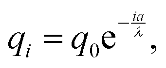 the total charge follows as geometrical series which due to
  converges, hence
 | (18) |
 . (The only profile that hits the discrete points and yields the same total charge is a sectionally linear profile.) The shift by
  when compared to 1 disappears in a rougher approximation leading to the same result as the continuous solution.
As we want to compare the continuous and the discrete distribution for the same Q we have two obvious possibilities. We could introduce a different  or we could use a different q0.
The first option is inadequate as the screening length λ is defined by bulk parameters  . The second way leads to a very insightful possibility. We adopt the above continuous profile with q0 at x′ = 0 but prolong the profile towards the interface up to
  (i.e. x = 0). As can be straightforwardly seen, this adds an additional contribution to the total charge which is given by

 the missing contribution.
Obviously starting at  (defining x = 0) yields a profile that hits all discrete values properly and yields a corrected total charge. If λ → a or a large space charge potential is established, q (x = 0) is still larger than q (x′ = 0). As we systematically smear out the discrete charge, the continuous profile q(x) adopts the discrete values qi in the interval
  if the potential does not become too high.
Now let us calculate the centroids for the low field approximation. In the continuous model we straightforwardly obtain  while this value is obtained for the discrete model only approximately. Here we made use of the fact that not only the geometrical series
  converges (as
  ) (eqn (18)) but also the geometrical series
 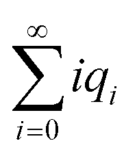 :
:
 | (19) |
 ,
, | (20) |
 and even further to
  .
.
 is identical to
  but for the precise centroid it holds that
  . The numerical check corroborates this deviation, and
  is indeed a much better approximation to
  .
.
Using eqn (11) with  one obtains the rather precise result
 | (21) |
 values in the ESI† (Table S1(a) and (b)). Moreover, the numerical calculations show that the deviation by
  is perceptible even though the validity of the exponential solution demands λ to exceed a.
The above conclusion that an adequate continuous picture for which the total charge coincides with the discrete one, implies an origin shift by  delivers a straightforward interpretation (see also ESI†). A shift between
  and
and  by
by  means that on an absolute scale the two centroids take identical positions (Fig. S2, ESI†). Unsurprisingly for very small λ, this cannot be the case and in fact the centroid correction tends towards zero rather than
  .
.  is then small and even more so
  as well as the difference between both. As the exponential solution is then no longer applicable, we have to inspect the full GC solution.
Indeed, as Fig. 4 shows, one then also recognizes the transition from  to 0. Since this correction becomes small, when on the other hand the centroid is close to the boundary, and since the correction becomes less important if λ increases, taking b + λ as effective difference in the double layer capacitance is a good approximation, yet eqn (21) is perceptibly more precise.
 | ||
| Fig. 4 Normalized Helmholtz correction (discrepancy between discrete result and Gouy–Chapman result) as a function of λ when the full Poisson–Boltzmann (a = b is assumed) is inspected. For large λ, the correction with respect to the full geometrical correction is due to the a/2-shift of the centroids. This figure shows the transition of Helmholtz correction from a/2 to a with decreasing λ. | ||
Fig. S3 (ESI†) investigates capacitance differences between continuous model and fully discrete model under constant surface potential and constant bulk concentration situation, respectively. For small storage, both models show similar results, while obvious discrepancies appear for large storage. The extracted Helmholtz corrections are also shown there.
Now let us come back to the problem of parallel conductance Y‖ and perpendicular resistance Z⊥. As already mentioned, discretization – if we refer to the same Q – does not give rise to improvements in this special context if only one carrier (the accumulated one for the parallel and the depleted one for the perpendicular experiments) is decisive (as shown in Fig. S4(a), ESI†). In these cases it is the overall charge that is the determinant. Yet the situation is different if the counter carrier is of influence as it is realized for small ψ (Fig. S4(b), ESI†). Table S2 (ESI†) gives some examples with various ϕ0.
Such investigations are particularly interesting when we consider non-idealities such as variations of the local (free) energy to form a carrier near the interface, more precisely deviations of μ0 from the bulk value.
Realistic model
Variations of μ0
Let us now inspect the effect of μ0-variations on the potential and concentration profiles. Even in the case of an ideally abrupt junction, it is clear that the first layer perceives a different environment than the other layers
  . Consider the extreme case that we may ignore interactions between the atoms in the first layer and the electron conductor. Then the bonding situation resembles that of a surface ion while for the layers
  approximately a bulk environment applies. In such a model μ0 is reduced to βμ0 at
  whereby a typical value of β maybe
  . Then, even if we stick to the Poisson–Boltzmann picture our analysis becomes slightly more difficult.
Now the GC-solution applies only from  to ∞ which we formally write as
  . In particular, this provides us with the integrated charge Q1 from
  to
to  : Q1 = fGC (ψ1).
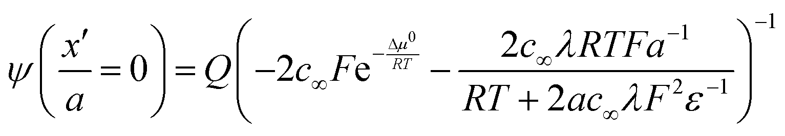
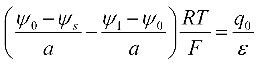
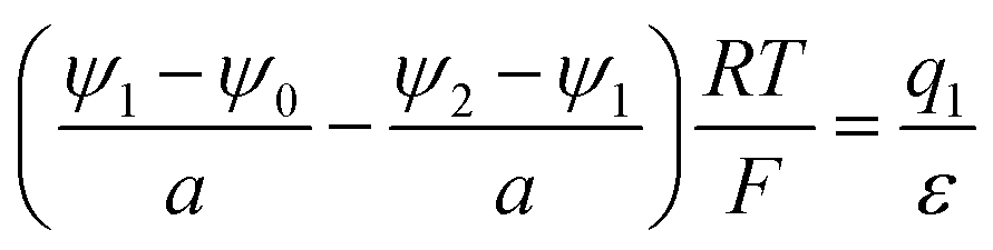
For the position x′ between −b and 0 and x′ between 0 and a, we have to apply Gauss’ law and the constancy of the electrochemical potential separately, which together with charge conservation supplies us with enough equations to solve the problem.
In detail for b = a:
(i) 
(ii) 
(iii) 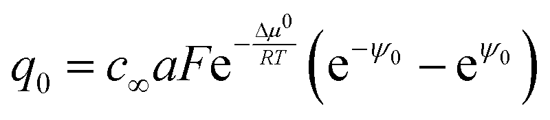
(iv) Q1 = fGC(ψ1)
(v) Q = Q1 + q0From these 5 equations the 5 unknowns ψs, ψ0, ψ1, Q1, q0 can be calculated if we take Q as independent variable.
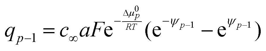
Here only eqn (iii) deserves a closer inspection. It follows from the constancy of + and −, whereby now μ0 at x′ = 0 differs from μ0 (x′ > 0) by Δμ0. This leads to
 | (22) |
 on an exponential solution is valid. The solutions for the potentials then follow as
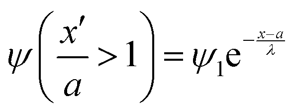 | (23a) |
 | (23b) |
 | (23c) |
 | (24) |
While the consideration of the conductance is essentially unaffected (given total charge), the profiles for concentrations and electric potentials are now more realistic close to the interface. Fig. 5 compares the profiles for electric potential and the charge carrier concentration if in the first layer μ0 differs from μ0 in the bulk by Δμ0, but the same overall excess charge is assumed. If Δμ0 is such that now the occupation of the first layer is favored (disfavored), the higher (lower) occupancy is naturally at the cost of lower (higher) c-values in the layers beneath (constant total charge assumed). (Table 1 displays the correspongding set of equations.) Such results might help to get a better understanding of the concentration profiles at heterojunctions involving solid electrolytes.
 | ||
| Fig. 5 The profiles of (a) electric potential and (b) charge carrier concentration shown as a function of number of lattice plane. The blue data shows the model with μ0-variation in the first layer adjacent to an electron conductor by Δμ0 (= −0.1 eV) with respect to the bulk (all the other layers). From second layer on the bulk value is applied. The blue curve shows the continuous model from second layer on. The red data shows the discrete model without μ0-variation. Blue and red dashed lines in (b) indicate the positions of centroid for both cases (with or without μ0-variation). Black dash-dotted line refers to the position of first layer. ψs, ψ0 and ψ1 in (a) refer to the normalized electric potential on the surface of electron conductor, in the first and second layer of ionic conductor, respectively. Simulation parameters: lattice spacing Δx′ = 0.1 nm; dielectric constant εr = 10; ϕs − ϕ∞ = −1 mV; c∞ = 1 × 10⁻⁵ mol cm−3; T = 298 K. Same total charge is applied for both models. | ||
Fig. 6 shows results for fully ionized oxygen vacancies in MgO using the formation values calculated in ref. 35 for a free surface assuming that there is an abrupt μ0-change from the first layer in the subsurface to the subsequent layers which all are characterized by the μ0-value of the bulk. The μ0 value for the first layer calculated for a free surface for our contact with an inert delocalized electron conductor is quite an approximation, but is justified here for the sake of demonstration.
 | ||
| Fig. 6 The profiles of (a) electric potential and (b) charge carrier concentration for fully ionized oxygen vacancies in MgO. The blue data shows the model with μ0-variation in the first layer adjacent to the surface by Δμ0 (= −1 eV) with respect to the bulk according to ref. 35. From second layer on the bulk value is applied. The blue curve shows the continuous model from second layer on. The red data shows the discrete model without μ0-variation. Blue and red dashed lines in (b) indicate the positions of centroid for both cases (with or without μ0-variation). Black dash-dotted line refers to the position of first layer. Simulation parameters: lattice spacing Δx′ = 0.42 nm; dielectric constant εr = 10; ϕ0 − ϕ∞ = −1 mV; c∞ = 1 × 10⁻⁵ mol cm−3; T = 298 K. Same total charge is applied for both models. | ||
At realistic junctions not only μ0 at the first adjacent layer differs from the bulk value, but the distortion can reach deeper. Such analysis is very well suited to realistically describe interfaces and provides a more appropriate correction than the consideration of interaction effect or elastic effects within the continuous framework. Fig. S4 (ESI†) shows the examples that μ0 at the first two layers differs from the bulk value.
As an example of practical worth we take defect formation values for SrTiO3 derived from DFT modelling34 and apply our approach to it. These examples are selected because they belong to the very rare cases where formation energies have been calculated for various lattice planes. Unfortunately the DFT results were obtained for neutral vacancies. We assume, and this is supported by the calculations for MgO35 that not the absolute values but the μ0-differences with respect to the bulk may, though probable somewhat larger, be not far from the values for the neutral defects. We further simplify our example (and this is also supported by calculations for MgO35) by using the same μ0-variations for the counter-carrier. Furthermore, as in the previous example we use these values derived for free surfaces for our contact with an inert delocalized electron conductor. Irrespective of the current availability of appropriate data, the example demonstrates that the consideration of atomistic modeling of the near-surface situation and the application of our composite approach is a simple powerful tool to tackle structural or elastic perturbations close to the interface.
Fig. 7a shows the calculated ψ-profile if such values are incorporated in the analysis. Here we use a Gouy–Chapman model in which the much less mobile counter carrier is enriched.
 | ||
| Fig. 7 The profiles of (a) electric potential and (b) charge carrier concentration for oxygen vacancies in SrTiO3. The blue data shows the model with μ0-variation in the first two layers adjacent to the surface by Δμ01, Δμ02 with respect to the bulk. From third layer on the bulk value is applied. The blue curve shows the continuous model from third layer on. The red data shows the discrete model without μ0-variation. Blue and red dashed lines in (b) indicate the positions of centroid for both cases (with or without μ0-variation). Black dash-dotted lines refer to the positions of first two layers. Simulation parameters: lattice spacing Δμ′ = 0.39 nm; dielectric constant εr = 300; ϕ0 − ϕ∞ = −1 mV; c∞ = 1 × 10⁻⁵ mol cm−3. Oxygen vacancy formation energy: first layer (5.9 eV); second layer (7 eV); bulk (7.5 eV), Δμ01 = −1.6 eV; Δμ02 = −0.5 eV (F0, neutral) ref. 34; T = 298 K. Same total charge is applied for both models. | ||
For many contacts it is more realistic to assume a Mott–Schottky model. This is even simpler to manage. As in the Mott–Schottky model the counter carrier (e.g. an acceptor impurity) is considered to be completely immobile we do not need assumptions with respect to its energetics.
Fig. 7b shows the situation for an accumulation of  . As the formation energy is lower close to the interface, the distribution shifts – for given Q – towards the interface, and so does the centroid and consequently the inverse space charge capacitance.
Fig. 8 shows the examples of centroid and space charge capacitance at various Δμ0-values in the first layer adjacent to an interface.
 | ||
| Fig. 8 Centroid (a) and space charge capacitance (b) as a function of μ0-variation in the first layer (Δμ0). From second layer on the bulk value is applied. Simulation parameters: lattice spacing Δx′ = 0.1 nm; dielectric constant εr = 10; ϕ0 − ϕ∞ = −1 mV; c∞ = 1 × 10⁻⁵ mol cm−3; T = 298 K. Same total charge is applied. | ||
Even though it is not the scope of the paper to analyze experimental results, it should be emphasized that for such a purpose one needs to refer to exactly the same conditions in modeling and experiments owing to the great sensitivity on space charge distributions.
For the sake of simplicity we have referred to vacancies as carriers. If we extend the analysis to interstitials we have to insert additional planes. This is particularly important for the very first layer as here the distance of nearest approach shrinks which is mirrored in the capacitance. Note that if a specific orientation (interstitials and vacancies sit on the same lattice plane) is considered, no additional planes are needed. An additional layer between x′ = b and x′ = 0 (see Fig. 1) has to be inserted, if internal ion adsorption is relevant. In such cases the integrated charge in the half-space (x′ ≥ 0) is compensated by the metal charge plus adsorption charge (ref. 2 and 12).
Fig. 9 gives a pertinent example.36 It refers to the Li2O–Ti interface which takes up additional Li via job-sharing. Here Li+ occupies such an interface-near site while the electron is redistributed mainly to the neighboring Ti-atoms. The extra Li leads to an additional electronic charge transfer towards the Ti adlayer (Fig. 9b). The transferred electronic charge is larger than that without extra Li atom (Fig. 9a).
 | ||
| Fig. 9 A stoichiometric Li2O layer (a) and a Li2O layer that exhibits a Li-excess (b). The excess Li+ is accommodated close to the Ti-interface and the excess electronic charges mostly the neighboring Ti-atoms. According to ref. 36. | ||
| (1) |

|
| (2) |
|
| (3) |
|
| … | … |
| (p + 1) |
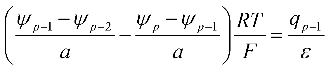
|
| (p + 2) |

|
| … | … |
| (2p + 1) |
|
| (2p + 2) | Q p = fGC(ψp) |
| (2p + 3) | Q = Qp + q0 + q1 + … + qp−1 |
Saturation effects
Not only can μ0-variations be implemented in a straight-forward way, also entropic saturation effects can be included. Here a Boltzmann distribution has to be replaced by a Fermi-type of distribution, i.e. where ctotal,± is the concentration of ± lattice sites (we ignore such effects on the electron conductor side). This correction is needed as the number of available sites (lattice sites) are no longer constant but become critical. The splitting into discretization close to the interface and a continuous description further away is very useful, as saturation effects should play a major role only close to the interface. In order to concentrate on this effect we set Δμ0 = 0 for
  and consider ψ ≪ 1. The exponential profile then can be used for
  . At x′ = 0 we have to replace
  in eqn (22) by
  with the results for local charge and potential (see Table 2).
| (1) |

|
| (2) |

|
| (3) |

|
| … | … |
| (p + 1) |

|
| (p + 2) |

|
| … | … |
| (2p + 1) |

|
| (2p + 2) | Q p = fGC (ψp) |
| (2p + 3) | Q = Qp + q0 + q1 + … + qp−1 |
Now we include saturation in the first layer.
Fig. 10 investigates this case. Evidently the qualitative effect is similar as if in the first layer Δμ0 were positive. The lower occupancy (at given total charge) leads then to a shift of  towards bulk corresponding to a lower space charge capacitance. Clearly the depression at the first layer to values lower than in the second layer (where saturation is neglected, Fig. 10a and b) would indicate the necessity to consider saturation also in the other layers or to restrict to smaller effects (Fig. 10c and d).
 | ||
Fig. 10 The profiles of (a) and (c) electric potential and (b) and (d) charge carrier concentration as a function of number of lattice plane. The blue data shows the model with saturation effects in the first layer adjacent to the interface. The blue curve shows the continuous model from second layer on. The red data shows the discrete model with absence of saturation effects. Blue and red dashed lines in (b) and (d) indicate the positions of centroid for both cases (with or without saturation effects). Black dash-dotted line refers to the position of first layer. Simulation parameters: lattice spacing Δx′ = 0.1 nm; dielectric constant εr = 10; ϕs − ϕ∞ = −1 mV; μ0 is constant; T = 298 K. (a) and (b) c∞/ctotal = 0.5 (unrealistic value). The charge concentration at first layer is smaller than that at next layers. Then considering saturation effects on next layers is necessary. (c) and (d) c∞/ctotal = 0.03. In this situation, the charge concentration at first layer is suppressed, but still higher than that at second layer. The qualitative effect is similar as if in the first layer Δμ0 were positive (the centroid shifts towards bulk direction slightly). Simulation parameters: lattice spacing Δx′ = 0.1 nm; dielectric constant εr = 10; ϕs − ϕ∞ = −1 mV; μ0 is constant; T = 298 K. (a) and (b) c∞/ctotal = 0.5 (unrealistic value). The charge concentration at first layer is smaller than that at next layers. Then considering saturation effects on next layers is necessary. (c) and (d) c∞/ctotal = 0.03. In this situation, the charge concentration at first layer is suppressed, but still higher than that at second layer. The qualitative effect is similar as if in the first layer Δμ0 were positive (the centroid shifts towards bulk direction slightly). | ||
A limited charge per layer has also been considered in ref. 19. In addition, the charge on the metal side may be subjected to restrictions of the density of states.
Permittivity variation
There are essentially three points leading to variation of the dielectric constant at the interface region, which are not independent: (1) at high fields (as they occur close to the boundary) dipoles tend to be oriented, and a change of polarization with applied field is small (field saturation). A quantitative relation has been given by Booth37,38 (see also the recommendable paper by Wang and Pilon39). (2) Polarization is less pronounced due to special interfacial effects. (3) The other side may not dielectrically contribute, which affects the effective permittivity. In a Gouy–Chapman picture these effects lead to a lower dielectric constant.40–42Fig. 11 investigates the ε-variation effects with Δμ0 = 0 and absence of site saturation. As an example εr in the first layer is taken to be 1 and from second layer on bulk-values (εbulk = 10) are applied. In this case, the centroid shifts slightly towards the interface direction and in our example the capacitance decreases from 8.6 μF cm−2 to 3.1 μF cm−2 according to
 | (25) |
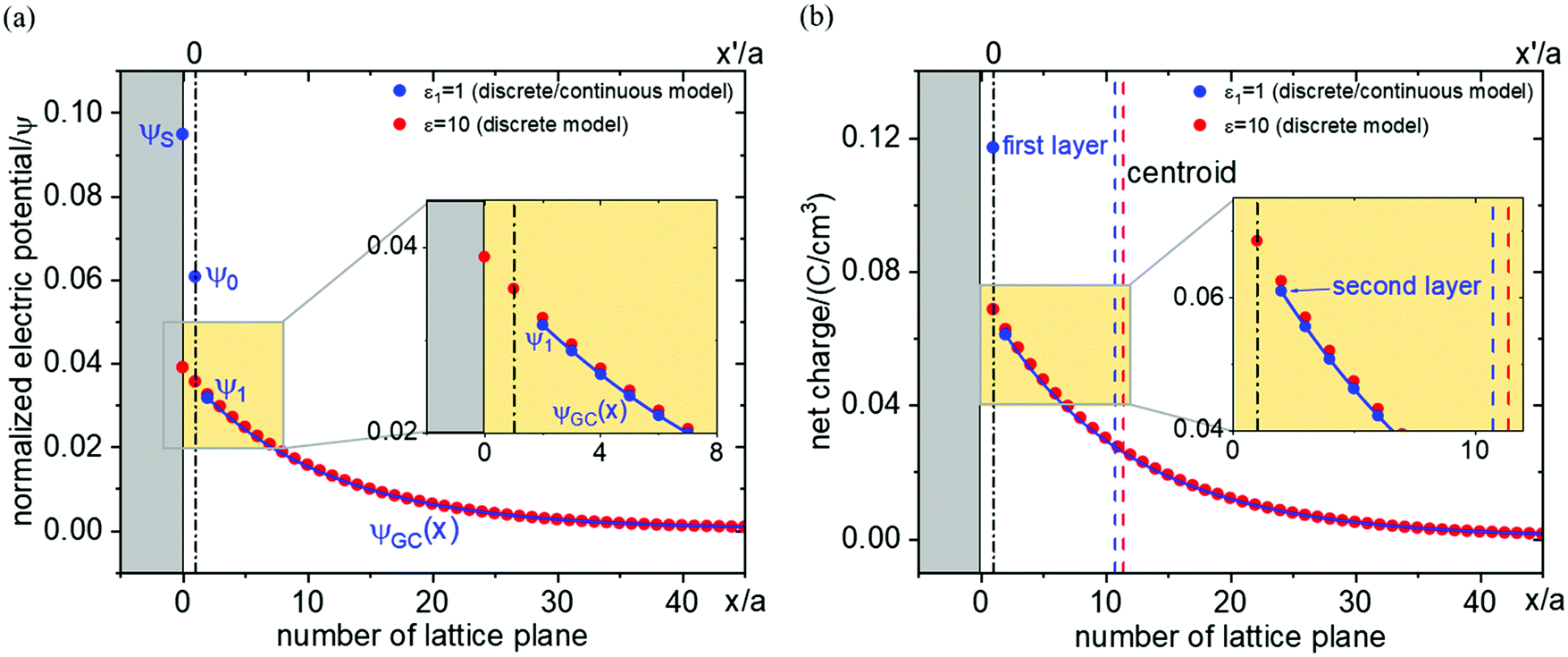 | ||
Fig. 11 The profiles of (a) electric potential and (b) charge carrier concentration shown as a function of number of lattice plane. The blue data shows the model with ε-variation in the first layer adjacent to the interface. The blue curve shows the continuous model from second layer on. The red data shows the discrete model without ε-variation. Blue and red dashed lines in (b) indicate the positions of centroid for both cases (with or without ε-variation). Black dash-dotted line is referring to the position of first layer. Simulation parameters: lattice spacing Δx′ = 0.1 nm; ϕs − ϕ∞ = −1 mV; c∞ = 1 × 10⁻⁵ mol cm−3; μ0 is constant; T = 298 K; εr at the first adjacent layer is taken to be 1, which differs from the bulk value (εbulk = 10). From second layer on the bulk values for ε are applied. 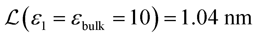 and and  . C (ε1 = εbulk = 10) = 8.6 μF cm−2 and C (ε1 = 1, εbulk) = 3.1 μF cm−2. Note the slight difference between red dots and blue line for x′ ≥ a. . C (ε1 = εbulk = 10) = 8.6 μF cm−2 and C (ε1 = 1, εbulk) = 3.1 μF cm−2. Note the slight difference between red dots and blue line for x′ ≥ a. | ||
For very small 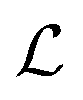 , ε-variation can have a considerable influence on the capacitance, which leads to a reduction of capacitance by one order of magnitude approximately in this situation. On the other hand, ε-variation in the first layer gives rise to a negligible capacitance change in the case of very large
  .
.
Conclusions
A variety of short-comings and unrealistic assumptions necessary for the validity of the Gouy–Chapman solution for ionic space charges can be overcome by 1D discrete modeling or a combination of 1D discrete modeling and continuum approach. Examples treated refer to variations in the energy levels, dielectric constant and exhaustion effects. Discretization also reveals details on the difference between space charge capacitance and measured capacitance. It is not completely removed by a Helmholtz correction, in more precise terms also an inherent small shift of the centroid of charge has to be considered.This approach is appropriate for handling realistic situations in particular at high space charge fields even though it does not remedy the inconsistency problem for the Poisson–Boltzmann equation as we still identify the potential of mean force with the mean potential.
Of particular value is the proposed composite approach which uses discretization close to the interface where the atomistic spacing matters and a continuum approach farther away (where also non-idealities are hardly significant). In the discretized zone knowledge (from atomistic modelling or experiments) about non-idealities (such as energetic variations owing to structural or elastic effects, variations in the dielectric permittivity or saturation effects) can be included in a straightforward way.
Conflicts of interest
There are no conflicts to declare.Acknowledgements
We thank Robert Usiskin, Eugene Kotomin, Davide Moia, Jochen Mannhart and Rotraut Merkle for discussions. Open Access funding provided by the Max Planck Society.References
- S. M. Sze and K. K. Ng, Physics of semiconductor devices, John wiley & sons, 2006 Search PubMed.
- J. O'M. Bockris and A. K. Reddy, Modern Electrochemistry, Ionics, Plenum Press, 1998, vol. 1 Search PubMed.
- C. Li, L. Gu, X. Guo, D. Samuelis, K. Tang and J. Maier, Charge Carrier Accumulation in Lithium Fluoride Thin Films due to Li-Ion Absorption by Titania (100) Subsurface, Nano Lett., 2012, 12(3), 1241–1246 CrossRef CAS PubMed.
- G. Gregori, R. Merkle and J. Maier, Ion conduction and redistribution at grain boundaries in oxide systems, Prog. Mater. Sci., 2017, 89, 252–305 CrossRef CAS.
- J. Maier, Ionic conduction in space charge regions, Prog. Solid State Chem., 1995, 23(3), 171–263 CrossRef CAS.
- J.-Y. Shin, D. Samuelis and J. Maier, Sustained Lithium-Storage Performance of Hierarchical, Nanoporous Anatase TiO2 at High Rates: Emphasis on Interfacial Storage Phenomena, Adv. Funct. Mater., 2011, 21(18), 3464–3472 CrossRef CAS.
- I.-D. Kim, A. Rothschild and H. L. Tuller, Advances and new directions in gas-sensing devices, Acta Mater., 2013, 61(3), 974–1000 CrossRef CAS.
- J. M. Thomas and W. J. Thomas, Principles and practice of heterogeneous catalysis. VCH, Weinheim, 1997 Search PubMed.
- C.-C. Chen and J. Maier, Decoupling electron and ion storage and the path from interfacial storage to artificial electrodes, Nat. Energy, 2018, 3(2), 102–108 CrossRef CAS.
- P. Lupetin, G. Gregori and J. Maier, Mesoscopic Charge Carriers Chemistry in Nanocrystalline SrTiO3, Angew. Chem., Int. Ed., 2010, 49(52), 10123–10126 CrossRef CAS PubMed.
- L. Fu, C.-C. Chen, D. Samuelis and J. Maier, Thermodynamics of Lithium Storage at Abrupt Junctions: Modeling and Experimental Evidence, Phys. Rev. Lett., 2014, 112(20), 208301 CrossRef.
- C.-C. Chen and J. Maier, Space charge storage in composites: thermodynamics, Phys. Chem. Chem. Phys., 2017, 19(9), 6379–6396 RSC.
- J. Maier, Physical chemistry of ionic materials: ions and electrons in solids. John Wiley & Sons, 2004 Search PubMed.
- J. Maier, Space Charge Regions in Solid Two Phase Systems and Their Conduction Contribution—II Contact Equilibrium at the Interface of Two Ionic Conductors and the Related Conductivity Effect, Berichte der Bunsengesellschaft für physikalische Chemie, 1985, 89(4), 355–362 CrossRef CAS.
- C. C. Liang, Conduction Characteristics of the Lithium Iodide - Aluminum Oxide Solid Electrolytes, J. Electrochem. Soc., 1973, 120(10), 1289–1292 CrossRef CAS.
- N. Sata, K. Eberman, K. Eberl and J. Maier, Mesoscopic fast ion conduction in nanometre-scale planar heterostructures, Nature, 2000, 408(6815), 946–949 CrossRef CAS PubMed.
- K. K. Adepalli, M. Kelsch, R. Merkle and J. Maier, Influence of line defects on the electrical properties of single crystal TiO2, Adv. Funct. Mater., 2013, 23(14), 1798–1806 CrossRef CAS.
- C.-C. Chen, L. Fu and J. Maier, Synergistic, ultrafast mass storage and removal in artificial mixed conductors, Nature, 2016, 536(7615), 159–164 CrossRef CAS PubMed.
- R. D. Armstrong and B. R. Horrocks, The double layer structure at the metal-solid electrolyte interface, Solid State Ionics, 1997, 94(1–4), 181–187 CrossRef CAS.
- A. Y. Shul’man and D. V. Posvyanskii, Solution of Self-Consistent Kohn–Sham and Poisson Equations for Quasi Two-Dimensional Electron Gas in the Accumulation Layer of Semiconductor with Nonparabolic Conduction Band, J. Exp. Theor. Phys., 2020, 130(6), 903–934 CrossRef.
- M. McEldrew, Z. A. Goodwin, A. A. Kornyshev and M. Z. Bazant, Theory of the double layer in water-in-salt electrolytes, J. Phys. Chem. Lett., 2018, 9(19), 5840–5846 CrossRef CAS PubMed.
- M. Z. Bazant, B. D. Storey and A. A. Kornyshev, Double layer in ionic liquids: Overscreening versus crowding, Phys. Rev. Lett., 2011, 106(4), 046102 CrossRef PubMed.
- M. S. Kilic, M. Z. Bazant and A. Ajdari, Steric effects in the dynamics of electrolytes at large applied voltages. I. Double-layer charging, Phys. Rev. E: Stat., Nonlinear, Soft Matter Phys., 2007, 75(2), 021502 CrossRef PubMed.
- J. P. de Souza and M. Z. Bazant, Continuum theory of electrostatic correlations at charged surfaces, J. Phys. Chem. C, 2020, 124(21), 11414–11421 CrossRef CAS.
- K. Vikrant, W. C. Chueh and R. E. García, Charged interfaces: electrochemical and mechanical effects, Energy Environ. Sci., 2018, 11(8), 1993–2000 RSC.
- D. S. Mebane and R. A. De Souza, A generalised space-charge theory for extended defects in oxygen-ion conducting electrolytes: from dilute to concentrated solid solutions, Energy Environ. Sci., 2015, 8(10), 2935–2940 RSC.
- S. Braun, C. Yada and A. Latz, Thermodynamically consistent model for space-charge-layer formation in a solid electrolyte, J. Phys. Chem. C, 2015, 119(39), 22281–22288 CrossRef CAS.
- G. Fisicaro, L. Genovese, O. Andreussi, N. Marzari and S. Goedecker, A generalized Poisson and Poisson-Boltzmann solver for electrostatic environments, J. Chem. Phys., 2016, 144(1), 014103 CrossRef CAS PubMed.
- A. Münster, Statistical Thermodynamics, Vol. II, Springer, Berlin, 1974 Search PubMed.
- M. Eigen and E. Wicke, The Thermodynamics of Electrolytes at Higher Concentration, J. Phys. Chem., 1954, 58(9), 702–714 CrossRef CAS.
- M. Schammer, B. Horstmann and A. Latz, Theory of transport in highly concentrated electrolytes, J. Electrochem. Soc., 2021, 168(2), 026511 CrossRef CAS.
- N. Lang and W. Kohn, Theory of metal surfaces: charge density and surface energy, Phys. Rev. B: Condens. Matter Mater. Phys., 1970, 1(12), 4555 CrossRef.
- J. Jamnik, Analysis of the frequency response of Schottky junctions in solid-state ionics, Appl. Phys. A, 1992, 55(6), 518–522 CrossRef.
- E. Kotomin, private communication.
- N. A. Richter, S. Sicolo, S. V. Levchenko, J. Sauer and M. Scheffler, Concentration of vacancies at metal-oxide surfaces: Case study of MgO(100), Phys. Rev. Lett., 2013, 111(4), 045502 CrossRef PubMed.
- Y. F. Zhukovskii, P. Balaya, E. A. Kotomin and J. Maier, Evidence for interfacial-storage anomaly in nanocomposites for lithium batteries from first-principles simulations, Phys. Rev. Lett., 2006, 96(5), 058302 CrossRef PubMed.
- F. Booth, The dielectric constant of water and the saturation effect, J. Chem. Phys., 1951, 19(4), 391–394 CrossRef CAS.
- F. Booth, Dielectric constant of polar liquids at high field strengths, J. Chem. Phys., 1955, 23(3), 453–457 CrossRef CAS.
- H. Wang and L. Pilon, Accurate simulations of electric double layer capacitance of ultramicroelectrodes, J. Phys. Chem. C, 2011, 115(33), 16711–16719 CrossRef CAS.
- R. Van der Berg, P. Blom, J. Cillessen and R. Wolf, Field dependent permittivity in metal-semiconducting SrTiO3 Schottky diodes, Appl. Phys. Lett., 1995, 66(6), 697–699 CrossRef CAS.
- D. J. Bonthuis, S. Gekle and R. R. Netz, Dielectric profile of interfacial water and its effect on double-layer capacitance, Phys. Rev. Lett., 2011, 107(16), 166102 CrossRef PubMed.
- J.-F. Olivieri, J. T. Hynes and D. Laage, Confined Water's Dielectric Constant Reduction Is Due to the Surrounding Low Dielectric Media and Not to Interfacial Molecular Ordering, J. Phys. Chem. Lett., 2021, 12(17), 4319–4326 CrossRef CAS PubMed.
Footnotes |
| † Electronic supplementary information (ESI) available. See DOI: https://doi.org/10.1039/d1cp05293d |
| ‡ Present address: Department of Chemical Engineering, National Taiwan University, No. 1, Sec. 4 Roosevelt Rd., Taipei, Taiwan 10617. |
| This journal is © the Owner Societies 2022 |