
 Open Access Article
 This Open Access Article is licensed under a Creative Commons Attribution-Non Commercial 3.0 Unported Licence
Development of an optical flow through detector for bubbles, crystals and particles in oils†
Peter R.
Birkin
 *a,
Jack J.
Youngs
a,
Tadd T.
Truscott
b and
Silvana
Martini
c
*a,
Jack J.
Youngs
a,
Tadd T.
Truscott
b and
Silvana
Martini
c
aDepartment of Chemistry, University of Southampton, Southampton, SO17 1BJ, UK. E-mail: prb2@soton.ac.uk
bDepartment of Mechanical and Aerospace Engineering, Utah State University, Logan, UT 84322-4130, USA
cDepartment of Nutrition, Dietetics, and Food Sciences, Utah State University, Logan, UT 84322-8700, USA
First published on 23rd December 2021
Abstract
The characterisation of bubbles or particles in an oil poses some unique challenges. In contrast to water solutions, the use of electrochemical detection approaches is more difficult in an oil. However, optical sensing systems have considerable potential in this area. Here we use a flow through channel approach and monitor the light propagation through this structure in an optical transmission sensor arrangement (OTS). This simple approach is demonstrated to be useful at detecting bubbles produced in the oil as a result of cavitation induced by high intensity ultrasound (HIU). The optical technique is shown to have an analytical basis. Bubble detection from an operating HIU source is shown to depend on position of the sensor with respect to the source. Critically, the bubble population can be followed for extended time periods after the ultrasonic source has been terminated. The detection of crystals is also demonstrated. Hence, this technique is ideal for the study of the effects of HIU on oils as they crystallise over extended time periods.
Introduction
The characterisation of bubbles1 and particles has been explored in a wide variety of different arenas.2 In water, for example, Coulter counter technologies have a wide range of applications from particle and cell sizing3,4 to DNA sequencing.5–9 In these cases, the passage or translocation of a particle from one vessel to another through a pore or constriction can be followed through monitoring of the ion current10,11 flowing through the restriction employed. The changes that result can be used to understand the size and shape of the object that is translocating. This has led to the development of a wide range of commercial technologies as well as an ongoing research effort. In other media, such as oils for example, this technique will be inhibited by the low inherent conductivity of the oil itself. Hence, ion current monitoring (or resistive pulse approaches) will be far more challenging. However, ion current systems are not the only way to size particles. For example, the displacement of fluid, through the Archimedes principle,12 has been used to follow and characterise particles in fluids. Other applications including the study of microbubbles13 and crystals14 are also noteworthy.Flow cytometry15 is perhaps the most closely related technique to the current study where the interaction of the particle with light is used to detect and characterise their presence and motion. Flow cytometry is an extremely powerful technique, and should be suited to oils, particularly as the particles or objects interact with light in some fashion. One such example of flow cytometry's possible remit is in the monitoring of oil crystallisation in the absence and presence of power ultrasound (or high intensity ultrasound, HIU).16–19 HIU has been shown to accelerate the kinetics of crystallisation in a number of different oil systems. In addition, HIU can cause changes in the physical properties of the resultant solid matrix.16,19,20 Hence, HIU has potential in the tailoring of the properties of an oil-based system. However, understanding the exact effects from HIU is far from simple. HIU is associated with the generation of cavitation events within the oils as well as motion and heating effects. Determining the exact effect of these different mechanisms on the oil's crystallisation process, and how this alters the physical properties of the solid matrix, is far from trivial.21 This is because the dynamics and lifetimes of bubbles generated within an oil, as well as other physical effects (such as shock wave generation22), needs to be put into the context of the nucleation and growth of the solid matrix.23,24 It is clear that further complimentary experimental observations are needed. One such measurement would involve sensors with the ability to detect the presence and motion of gas bubbles during and after HIU treatment. Unfortunately, conventional high-speed imaging25,26 can only provide some information in this context. This is due to the oil crystals initially having a relatively small dimension (e.g., microns) and a large population (resulting in growing opacity of the oil). To circumvent these issues, we have developed a simple and robust sensor, based on a flow cytometry principle, and applied it to a crystallising media.
Typically, light transmission or scatter at 90° (including fluorescent studies), increase the amount of information recovered from these techniques. This has led to a range of commercial instruments being available. However, for the application reported here, a bespoke approach was necessary. This approach centred on a sensor that was useful in accessing the lifetime of gas bubbles generated by HIU and the detection of lipid crystals. The development and performance of this optical transmission sensor (OTS), and this approach, are now reported.
Methods
Materials
Experiments were performed using two media, soybean oil (SBO, Clearsprings) and all-purpose shortening (APS, Bunge). The fatty-acid chemical composition of the APS sample was 42% palmitic acid (C16:0), 38% oleic acid (C18:1), and 11% linoleic acid (C18:2). The melting point was 35.1 ± 0.4 °C. See ref. 27 for further details.Crystallisation experiments
APS samples were melted in a microwave oven and then stored in an oven at 80 °C for 30 minutes to remove residual crystal memory. The melted sample (100 g) was transferred to a double-walled thermostatic crystallisation cell connected to an external water bath (Grant, LT ecocool 100), set to the relevant crystallisation temperature (Tc).Sensor construction and operation
The sensor was fabricated using a glass capillary (Fisher, 1.9 mm OD, ∼1.6 mm ID). A Vishay photodiode (RS components, 1206 surface mount) and a 1206 LED (Red, RS components) were used as the detector and emitter respectively. These were placed on opposite sides of the glass capillary. The whole arrangement was set in epofix resin (Struers) and polished down (88 grit) followed by 1 μm alumina (Struers) on microcloth (Metprep) until the opening to the channel was 0.78 mm from the surface of the support structure (determined using a microscope). An image and schematic of the sensor are shown in Fig. S1 (ESI†) and Fig. 1. The size of the photodiode, LED and capillary were chosen for a number of reasons. First, the capillary size is suitable for the particles expected in the experiments. Second, flow into the sensor can be achieved with simple pressure generation apparatus. This is important particularly considering the viscosity28 of the media and the Hagen-Poiseuille-relationship.29 Third, the photodiode is suitable for the particle sizes targeted. Lastly, one could change the dimension/geometry of the system (talking into account of the points raised above). However, larger photodiodes may be a disadvantage, as the signal expected for the same particle should scale with the inverse of the sensor area (see later discussion). Lastly, the dynamics of clusters and transient flashes have been probed with similar detectors.30 This suggests that the approach adopted here should be able to sense bubbles dynamics within this environment although consideration of the effects of viscosity, fluid flow and the constriction with the capillary should not be overlooked. | ||
Fig. 1 Schematic representation of the experimental setup. Here a piston like emitter acts as the source for HIU. Under the conditions employed a cluster (C) is formed at the surface of the probe ( ). Gas bubbles originating in this zone ( ). Gas bubbles originating in this zone ( ) or crystals ( ) or crystals ( ) are drawn into the pore and travel between the LED light source and the photodiode detector (PD). The blue arrows indicate the motion of the gas bubbles/particles as they travel through the channel while the orange arrow indicates the motion of the PLE. ) are drawn into the pore and travel between the LED light source and the photodiode detector (PD). The blue arrows indicate the motion of the gas bubbles/particles as they travel through the channel while the orange arrow indicates the motion of the PLE. | ||
Sensor calibration
The sensor was calibrated using a series of spheres (Simply bearings, 0.25 mm and 0.5 mm radius). These were suspended in oil and passed through the OTS. Further calibration was achieved with a polydispersed sample (glassy carbon 200–400 μm, Alfar Aesar) suspended in SBO. In order to estimate the range of particle sizes present, a sample of these particles were assayed using optical microscopy (see ESI,† data and Fig. S9) and imageJ analysis. The distribution was then compared to the manufacturers’ data sheet. Data from the optical assay was then compared to the OTS sensor response. Events that were beyond the range expected were ignored. This was supported by noting that these large events were composed of multiple simultaneous transits attributed to conglomerates (see ESI,† data and Fig. S9–S11). The remaining events were then used to gauge the response for a 200-400 μm diameter particle with the range of responses attributed to the extremes of the quoted values. The calibration procedure is based on an occlusion principle. In effect, the shadow created by the calibration sphere reduces the output of the photodiode in an appropriate proportion related to the cross-sectional area of the particle deployed. Surface effects or refractive index features are assumed minimal in this approach.HIU setup
Cavitation was generated using a ‘piston like emitter’ (PLE, Misonix, XL2000, ∼23 kHz, or a Misonix, S3000, 20 kHz) immersed in the relevant media here an oil (SBO or APS). A 3.2 mm diameter tip (e.g., a P1 tip) was employed in all cases. The tip of the PLE was not polished as this was found not to be conducive to the formation of stable clusters in these oil systems (see ref. 31 and ESI,† data and Fig. S8). Hence in all cases an eroded tip was used. Erosion of material from the tip of the ultrasonic source cannot be ruled out. However, we have no physical evidence for this at this time. Nevertheless, this may play a role in the nucleation process, the magnitude of which requires further quantification. The OTS was positioned with respect to the PLE tip using micrometers and stages (Thor labs).Data capture
The LED was driven with a DC power supply and a simple amplifier31 was used to detect the signal from the photodiode (gain 1 × 10⁶). The signal was recorded using a USB204 or a PCI DAS 14020/12 DAQ system (Measurement computing) at 50 kHz unless stated otherwise in the appropriate figure legend. The data was captured using software written in VB2010 incorporating Measurement studio (National Instruments). Data analysis (e.g., for frequency components, plotting or peak finding) was undertaken using a bespoke program (VB2010 and Measurement studio). The data was analysed with a moving window, which was ∼2 ms long (45 cycles of the PLE) moved through the data in 0.2 ms steps. High-speed imaging was performed using a Photron APX RS camera and a Navitar 12× lens. The images were illuminated using a LED backlight.Crystal microstructure
A polarised light microscope (PLM-Olympus BX 41, Tokyo, Japan) fitted with a digital camera (Infinity 2, Lumenera Scientific, Ottawa, Canada) was used to record the crystal microstructure of crystallised lipid material. Images were recorded before and after approximately 20 minutes after initial sample cooling.Fluid sampling
To enable bubble of crystal capture, a simple pressure rig was deployed. In this case a gas syringe (120 ml, Rapid Electronics) was used and a mass loaded onto the syringe to generate a constant pressure.32 The pressure applied to the system was monitored using an EBRO vacuum meter VM 2000 gauge. A schematic representation of the setup is shown in Fig. S2 (ESI†).Results and discussion
Fig. 1 shows a schematic representation of the experimental arrangement and the sensor setup. In this system, a LED and photodiode are placed parallel to one another across a 1.6 mm OD capillary tube. Fluids (oils) were drawn into this tube and through the space between the light source and the detector using a gas syringe and weight system (see Fig. S2, ESI†). In order to calibrate this system, a series of solid spheres were driven through the system. The response of the sensor was then monitored as these spheres passed between the LED source and the detector. The area occluded as the sphere passed in front of the detector was calculated considering the reduction in the signal from the sensor and the area of the detector (0.85 mm2). Fig. 2 shows a plot of the response of the sensor as a function of the calibration sphere size deployed (•). The solid line ( ) shows the fit to the data to eqn (1)
| ΔA = kπrp2 | (1) |
| ΔA = [ΔVots/Vblots]AS | (2) |
| rp = [ΔVotsAs/Vblotsπk]1/2. | (3) |
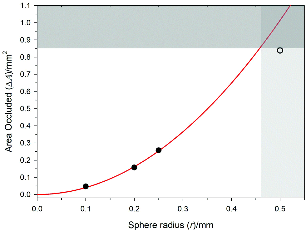 | ||
Fig. 2 Plot showing the calibration data for solid spheres passed through the sensor in oil. The solid circles (•) represent data where the sensor can be used analytically as described in the text. The open circle (○) represents a sphere, which is outside of the sensor's capabilities. The red line ( ) represents the fit of the data to the model to calculate the calibration factor for the sensor. The shaded regions represent two limiting cases; (A) represents the absolute area of the photodiode sensing area while (B) represents the limit imposed by a square sensing element. ) represents the fit of the data to the model to calculate the calibration factor for the sensor. The shaded regions represent two limiting cases; (A) represents the absolute area of the photodiode sensing area while (B) represents the limit imposed by a square sensing element. | ||
There are some limitations in the system that should be noted. First, the photodiode sensing area is 0.85 mm2. Hence, this represents an upper area limit and is included in Fig. 2 as shaded region (A). Second, the geometry of the sensor is square. Hence, calibration spheres with a radius in excess of this critical dimension (r ≥ 0.46 mm) cannot be accurately sized. This is included in Fig. 2 as shaded region (B). To illustrate this point, a 0.5 mm radius calibration sphere was also investigated. The response of the sensor (○) deviates below that predicted by eqn (1) and is at the complete sensor area, 0.85 mm2. However, this is understandable as this is outside of the spherical size range, which can be accurately sized using this approach. Nevertheless, the sensors calibration can be used within these limits to size objects below this upper limit and above the signal to noise floor that is inherent in any sensor system.
Fig. 3 shows the response of the sensor when it has been placed in an APS medium. In this case, the oil has been cooled to such a temperature to allow for the crystallisation of the bulk sample. A pressure gradient is applied to the system to allow for a small flow of oil through the sensor. In this experiment, no other stimuli (for example HIU) have been applied to the oil system. Instead, the oil is allowed to crystallise, and the presence of these crystals detected by the flow through the optical transmission sensor (OTS). Fig. 3 shows two examples where the APS oil sample has been cooled to a different temperature (representing different degrees of supercooling). Fig. 3(a) shows the response of the OTS sensor to crystals formed at a relatively high supercooling regime (ΔTsc = 9 °C). Under these conditions, the OTS shows small transients just above the noise floor and a significantly reduced baseline (compared to the initial value, ∼4.9 V). This indicates that the transparency of the oil has reduced presumably because of the collective effect of small crystals in the OTS channel, which are individually below the detection limit of the OTS. However, if the supercooling is reduced to (ΔTsc = 5 °C), Fig. 3(c), larger transients are detected under otherwise similar conditions. This is explained by the size of the crystals that form under the conditions selected. Fig. 3(b) and (d) show representative cross polarised microscope images of samples taken from the bulk of an oil sample. These show that at ΔTsc = 9 °C, image (b), crystallites with radii below ∼25 μm are the predominant size produced. In turn, the OTS is unable (see Fig. 3(a)) to detect accurately these individual small crystals although there is evidence of transients in the data recorded. Under the conditions stated, a 50 μm diameter crystal is expected to produce a voltage transient of approximately 15 mV. This is close to the noise level shown in Fig. 3(a) but may collectively lower the optical transparency of the media accounting for the reduced baseline in Fig. 3(a) and the small transients seen in the data. In contrast, considering the crystals formed at lower supercooling conditions, Fig. 3(d) shows that the crystals are of the order of 200 μm in diameter. An object of this size would be expected to cause a transient of approximately 235 mV. This is of the order detected in the data shown in Fig. 3(c). Fig. 4 shows the distribution of detected crystal sizes for the data run shown in Fig. 3(c). This distribution indicates that the majority of events have an estimated diameter <200 μm in reasonable agreement with the microscopy image shown in Fig. 3(d). Lastly, the baseline of Fig. 3(c) is higher than the increased supercooling regime (Fig. 3(a)). Presumably, the media at 30 °C is populated with fewer larger crystallites (compared to Fig. 3(a)) so that the bulk transparency of the fluid is higher at this temperature. This leads to a higher baseline under the conditions stated.
 | ||
| Fig. 3 Plots ((a) and (c)) showing OTS signal as a function of time demonstrating the detection of individual crystals in an APS sample in the absence of HIU after ∼20 min of initial sample cooling. Crystallisation temperatures were 26 °C (a) and 30 °C (c). The local minima (○), determined using a peak finding algorithm, is highlighted in (c) only as the events in (a) where deemed too small to determine accurately from the noise. The data is shown with a 25-point moving average applied to the data in both cases. The OTS was positioned centrally at the base of the cell. A pressure differential of −113 mbar was applied across the OTS sensor. Images (b and d) show representative cross-polarised microscope images of the crystallites formed at 26 °C (b) and 30 °C (d) under the same conditions. The scale bar represents 100 μm. | ||
 | ||
| Fig. 4 Plot showing the estimated crystal size population calculated from the transients detected and shown in Fig. 3c (○). | ||
Some limitations need to be noted. First, these calculations assume spherical particles and the images shown in Fig. 3 suggest that the crystals may deviate from this. Second, the calibration data was performed on solid particles rather than crystals, which will introduce an error. This could include refractive index effects or other optical phenomena. Third, an individual transient (such as those shown in Fig. 3c) may be a collection of particles translocating together. Nevertheless, these results indicate that the OTS is able to detect crystals within a crystallising media, show that the supercooling conditions can be detected and, finally, that the size regime is as expected (noting the limitations suggested). Lastly, some of the transients are accompanied by small rises in the photodetector signal as the crystal enters of exits the detection zone. This is presumably an optical effect that is beyond the current scope of investigation reported here. However, it is noted that these appear associated with larger fat conglomerates/clusters of spherulites. In addition, calibration experiments with sold glassy carbon spheres do not appear to show these features (see ESI†). Clearly, although these features are small, more investigation is needed to ascertain the origin of these transients and possibly exploit them to gather useful information on the particles under investigation.
Turning to the application of HIU to these oil systems, the OTS was deployed in an oil to detect the presence of gas bubbles produced through the ultrasonic treatment of these fluids. Fig. 5 shows the response of the OTS in the presence of a bubble population generated by a HIU source. The transient reductions in the signal from the OTS system indicate that bubbles produced through the treatment of the oil can be drawn into the OTS device where they cause a loss in signal as they translocate through the channel. The magnitude of these transient reductions in the signal are attributed to the size of the bubbles moving between the LED and the photodiode. Hence, the variety of the responses recorded indicate that there is a distribution of bubbles within the population generated within this environment as expected. The largest of these transients (up to ∼4 V) indicate that the bubbles produced in this environment are up to a radius of 0.41 mm in size. Included in Fig. 5 is the effect of the vertical distance between the OTS and PLE. Fig. 5 shows that as the distance between the OTS and the PLE increases the event frequency decreases. This is included in the figure as the number of separate events.
 | ||
Fig. 5 Plot showing the bubble capture as a function of vertical separation between the PLE and the sensor in aerobic liquid soybean oil over a 10 s period. Each plot depicts the translocation of gas bubbles generated by HIU with a PLE tip driven at 32 WRMS (f ∼ 22.6 kHz). The OTS was positioned centrally at the base of the cell directly below the PLE. The separation between the PLE and the OTS was 20 mm ( ), 10 mm ( ), 10 mm ( ) and 2 mm ( ) and 2 mm ( ) above the OTS support surface, with a horizontal displacement of 2 mm from the channel opening. A pressure differential of −113 mbar was applied across the channel and the sample temperature was 23.2 °C. ) above the OTS support surface, with a horizontal displacement of 2 mm from the channel opening. A pressure differential of −113 mbar was applied across the channel and the sample temperature was 23.2 °C. | ||
Some care must be employed in the actual number of events detected, as it is always difficult to determine single from multiple events through transient counting. Nevertheless, the data clearly shows that as the distance between the OTS and the PLE is increased, the event frequency reduced significantly.
This implies that the size and number of gas bubbles that can be detected using the sensor is strongly distance dependant. This is further illustrated if the OTS is moved horizontally away from the PLE tip (and the cluster that forms in this region). Fig. S3 (ESI†) shows how the event frequency drops dramatically as the OTS sensor was moved in the horizontal plane over a distance of 5 mm. These results indicate that the capture of bubbles and their detection is extremely location dependant. This is as expected if one considers the generation mechanism present in this environment. For example, the PLE tip of the HIU source produces a large cluster of bubbles, which grow and collapse in a two-stage process.26 In addition, a stream of bubbles form at the base of this event.31 Hence, moving the OTS sensor into and out of this dense bubble stream would be expected to alter the size and number of bubbles captured by the device.
Fig. 6 shows a set of images taken from a high-speed camera used to study the translocation of a single bubble through the OTS device. In this case, the motion and shape of a bubble (labelled ‘B’) can be noted. The images reveal some interesting features. First, the bubble is distorted from a spherical shape within the channel of the OTS and resembles an inverted spherical cap.33 This is unusual but may be linked to the flow profile in the capillary and the acoustic pressure environment present. Second, the size of the bubble appears to change as a function of time (e.g., (a) resembles a semi-spherical bubble but in (b), the same bubble has become smaller and more like a spherical cap). Third, some scattering of light, from the LED source, can be clearly seen on the wall of the bubble itself. These observations suggest that the bubble is subject to the pressure field within the cell and may be distorted through the forces present in the channel. The acoustic pressure field is composed of the source (HIU) and the response of the bubble population within the environment. In this latter case, the cluster of bubbles at the tip of the PLE, produces a strong pulse-like emission associated with the subharmonic nature of its collapse. This has been shown previously to cause bubble oscillation within a channel of a micropore in an aqueous environment.10 In that case, however, the oscillation was detected through the perturbation of the ion current flowing through the pore and the data captured in a water system. In the work reported here, the use of the oil media makes ion current sensing more difficult. To circumvent this, the OTS response was investigated to determine whether similar bubble oscillations could be detected in an oil. Fig. 7 shows the response of the OTS recorded with a time resolution of 2 μs. Here a single translocation in the presence of the cluster at the PLE tip is shown. At this temporal resolution, clear oscillations in the signal can be seen. These oscillations continue until the bubble starts to exit the sensing area (at ∼800 ms). This may be associated with the physical conditions in the channel as the bubble moves further into the structure. The oscillations in the signal appear to have regular ‘spike like’ transients. These are spaced at ∼220 μs apart. This is five periods of the HIU source and suggests that the cluster in this system collapses with a frequency of f/5 (where f is the frequency of the ultrasonic source, in this case a ∼22.5 kHz PLE).26 Further information can be gathered from this data by analysing the frequency components as a function of time for a set of bubble translocations. Fig. 8 shows these components. Included in the figure are the corresponding OTS signal as a function of time. The frequency analysis shows that under these conditions the OTS signal has a set of subharmonics (and ultraharmonics, not shown) which are indicative of the periodicity associated with an f/5 cluster. In addition, if the PLE power level was reduced to 18 Wrms, the dynamics change, and the frequency components associated with an f/4 cluster were detected (see Fig. S4, ESI†). These results suggest that the permanent gas bubbles within the channel of the OTS are sensitive to the pressure field generated in the bulk. In the oil system, this is predominantly the large pressure pulses emitted by the cluster produced at the tip of the PLE. This observation has several implications. First, bubbles in an oil may be discriminated from solid particles (which are not expected to alter their shape as dramatically in response to an alternating pressure field) through their oscillatory behaviour as they translocate through such a sensor.
 | ||
Fig. 6 High-speed images showing bubble oscillation of a single ultrasonically generated microbubble (B) during translocation through the OSS device in liquid soybean oil. The boundary between the opto-counter and the soybean oil (blue line,  ) and the channel (yellow lines, ) and the channel (yellow lines,  ) within the device are highlighted. The frame rate was 12 kfps with a shutter speed of 83.3 μs. The time points of the individual frames were a = 2.64825 s; b = 2.64833 s; c = 2.64842 s; d = 2.64850 s. HIU was applied at 32 Wrms, the pressure differential applied to the channel was −114 mbar and the temperature was 24.8 °C. Shadows within the images for regions outside the yellow lines indicated in frame (a) can be disregarded, as they are part of the epoxy support. The white scale bar represents 500 μm. ) within the device are highlighted. The frame rate was 12 kfps with a shutter speed of 83.3 μs. The time points of the individual frames were a = 2.64825 s; b = 2.64833 s; c = 2.64842 s; d = 2.64850 s. HIU was applied at 32 Wrms, the pressure differential applied to the channel was −114 mbar and the temperature was 24.8 °C. Shadows within the images for regions outside the yellow lines indicated in frame (a) can be disregarded, as they are part of the epoxy support. The white scale bar represents 500 μm. | ||
 | ||
Fig. 7 Plot showing the OTS response as a function of time ( ) of an individual translocation event detected in aerobic liquid soybean oil at 26 °C. The HIU source operated at 32 Wrms ultrasonic power. Data captured at 5 · 105 Hz. A constant pressure differential of −114 mbar was employed. ) of an individual translocation event detected in aerobic liquid soybean oil at 26 °C. The HIU source operated at 32 Wrms ultrasonic power. Data captured at 5 · 105 Hz. A constant pressure differential of −114 mbar was employed. | ||
 | ||
Fig. 8 Plots showing the OTS signal as a function of time ( ). The sample consisted of SBO. An ultrasonic power of 32 Wrms was employed. The data was captured at 5 × 10⁵ Hz with a pressure differential applied across the OTS channel for gas bubble detection of −114 mbar. The SBO was at 26 °C. The lower plot shows the subharmonic components. In this case, the data shows the presence of a response indicative of an f/5 cluster. The individual subharmonic components are marked for reference. The contour scale has units of volts. ). The sample consisted of SBO. An ultrasonic power of 32 Wrms was employed. The data was captured at 5 × 10⁵ Hz with a pressure differential applied across the OTS channel for gas bubble detection of −114 mbar. The SBO was at 26 °C. The lower plot shows the subharmonic components. In this case, the data shows the presence of a response indicative of an f/5 cluster. The individual subharmonic components are marked for reference. The contour scale has units of volts. | ||
Hence, bubbles and crystals could be distinguished by looking at the associated frequency components as they translocate. Second, the pressure field within the media can be probed by looking at the frequency components present in bubble translocation. This will be of use where other sensors are unavailable or impractical. The motion of these gas bubbles (which can be categorised as non-inertial or stable cavitation events) may play a role in aiding the crystallisation process through secondary effects, for example. To ascertain the level of this effect, further consideration of the motion and shear generation in relation to the materials involved is necessary.
Turning to longer time scale experiments. Two comparative sets of data where gathered. In the first, a non-crystallising oil (soybean, SBO) was exposed to HIU for a period of 10 s. In this case the OTS showed the detection of bubbles within the media for periods up to 300 s after the initial HIU exposure (see Fig. S5, ESI†). Over this period the size and frequency of the events clearly fall. However, the OTS data suggests that bubbles may be detected in the oil for significant periods after the HIU has been terminated (at least 300 s). Presumably, the loss of the larger events suggests that the larger bubbles in the population are lost first through buoyancy forces (Stokes law34). In the second system, a similar experiment but with ‘all-purpose shortening’ (APS) exposed to HIU for 10 s was undertaken. However, in this case the experiment was performed below the crystallisation temperature of the APS sample (Tc = 30 °C). Again, the presence of bubbles was detected over a significant time-period. However, the crystallisation process could be followed as a gradually decreasing baseline signal was registered for the OTS (see Fig. S6, ESI†). This suggests that the sensor can detect bubbles, crystals, and the effect of both on the overall optical opacity of the sample. This implies that the technique may be of use in following the kinetics of the crystallisation process as well as the mechanistic details (e.g., bubbles and larger crystals) under appropriate conditions.
Lastly, the processes, which occur within the crystallising system in the presence of HIU, are complex with primary and secondary nucleation possible. Evidence for these effects have been proposed for other systems.16,35,36 The OTS, if refined to gather the relevant data, may be a valuable tool from probing these mechanisms. This may involve looking at bubble nucleation or fat particles associated with small bubble entities.
Conclusions
The results presented here show that the OTS sensor is both simple and useful in the detection of bubbles and crystals within an oil media. It has an empirical basis, and providing the calibration is undertaken and the limitations considered, is able to size particles as they translocate through a channel. These particles can be either solid crystals formed in the bulk media, solid particles or gas bubble produced by an ultrasonic source. In the former case, the size of the particles detected match reasonably images of the crystals produced under the conditions employed. In the last case, bubbles can be detected in the locality of the PLE employed. In addition, oscillation of these bubbles in response to the pressure field generated in the system can be detected and used to indicate the type of cluster dynamics present. These results suggest that it may be possible to distinguish between solid particles and bubbles within the same system by monitoring the frequency components present in the translocation signal.Conflicts of interest
There are no conflicts to declare.Acknowledgements
This project was supported by Agriculture and Food Research Initiative (AFRI) Grant No. 2017-67017-26476 from the USDA National Institute of Food and Agriculture, Improving Food Quality – A1361. This paper was approved by the Utah Agricultural Experiment Station as Paper Number 9470.References
- W. Lauterborn and T. Kurz, Physics of bubble oscillations, Rep. Prog. Phys., 2010, 73, 106501 CrossRef
.
-
F. R. Young, Cavitation, Imperial College Press, London, 1999 Search PubMed
-
W. H. Coulter, Means for counting particles suspended in a fluid, US Pat., 2656508, 1953 Search PubMed
- R. W. DeBlois and C. P. Bean, Counting and sizing of submicron particles by the resistive pulse technique, Rev. Sci. Instrum., 1970, 41, 909–916 CrossRef
- R. Peng and D. Li, Detection and sizing of nanoparticles and DNA on PDMS nanofluidic chips based on differential resistive pulse sensing, Nanoscale, 2017, 9, 5964–5974 RSC
- D. Branton, D. W. Deamer, A. Marziali, H. Bayley, S. A. Benner, T. Butler, M. Di Ventra, S. Garaj, A. Hibbs, X. Huang, S. B. Jovanovich, P. S. Krstic, S. Lindsay, X. S. Ling, C. H. Mastrangelo, A. Meller, J. S. Oliver, Y. V. Pershin, J. M. Ramsey, R. Riehn, G. V. Soni, V. Tabard-Cossa, M. Wanunu, M. Wiggin and J. A. Schloss, The potential and challenges of nanopore sequencing, Nat. Biotechnol., 2008, 26, 1146–1153 CrossRef CAS PubMed
- Y. Ding, A. M. Fleming, H. S. White and C. J. Burrows, Internal vs. Fishhook Hairpin DNA: Unzipping Locations and Mechanisms in the α-Hemolysin Nanopore, J. Phys. Chem. B, 2014, 118, 12873–12882 CrossRef CAS PubMed
- H. Bayley and C. R. Martin, Resistive-pulse sensing – from microbes to molecules, Chem. Rev., 2000, 100, 2575–2594 CrossRef CAS PubMed
- J. Clarke, H. C. Wu, L. Jayasinghe, A. Patel, S. Reid and H. Bayley, Continuous base identification for single-molecule nanopore DNA sequencing, Nat. Nanotechnol., 2009, 4, 265–270 CrossRef CAS PubMed
- P. R. Birkin, S. Linfield and G. Denuault, The In situ Electrochemical Detection of Microbubble Oscillations during Motion through a Channel, Phys. Chem. Chem. Phys., 2019, 21, 24802–24807 RSC
- D. A. Holden, J. J. Watkins and H. S. White, Resistive-pulse detection of multilamellar liposomes, Langmuir, 2012, 28, 7572–7577 CrossRef CAS PubMed
- K. Nidhi, S. Indrajeet, M. Khushboo, K. Gauri and D. J. Sen, Hydrotropy: A promising tool for solubility enhancement: A review, Int. J. Drug Dev. Res., 2011, 3, 26–33 Search PubMed
- J. Tu, J. E. Swalwell, D. Giraud, W. Cui and T. J. Matula, Microbubble Sizing and Shell Characterization Using Flow Cytometry HHS Public Access, IEEE Trans. Sonics Ultrason., 2011, 58, 955–963 Search PubMed
- A. Hernandez-Santana, A. Yavorskyy, S. T. Loughran, G. M. McCarthy and G. P. McMahon, New approaches in the detection of calcium-containing microcrystals in synovial fluid, Bioanalysis, 2011, 3, 1085–1091 CrossRef CAS PubMed
- J. Picot, C. L. Guerin, C. L. Van Kim and C. M. Boulanger, Flow cytometry: Retrospective, fundamentals and recent instrumentation, Cytotechnology, 2012, 64, 109–130 CrossRef PubMed
- Y. Ye, A. Wagh and S. Martini, Using high intensity ultrasound as a tool to change the functional properties of interesterified soybean oil, J. Agric. Food Chem., 2011, 59, 10712 CrossRef CAS PubMed
- S. D. Campbell, H. Douglas Goff, D. Rousseau, J. A. Rincón-Cardona, L. M. Agudelo-Laverde, M. L. Herrera, S. Martini, F. Chen, H. Zhang, X. Sun, X. Wang, X. Xu, Y. Ye and S. Martini, Application of High-Intensity Ultrasound to Palm Oil in a Continuous System, J. Am. Oil Chem. Soc., 2015, 81, 319–327 Search PubMed
- A. H. Suzuki, J. Lee, S. G. Padilla and S. Martini, Altering functional properties of fats using power ultrasound, J. Food Sci., 2010, 75, E208–E214 CrossRef CAS PubMed
- J. Lee, R. C. da Silva, V. Gibon and S. Martini, Sonocrystallization of Interesterified Soybean Oil: Effect of Saturation Level and Supercooling, J. Food Sci., 2018, 83, 902–910 CrossRef CAS PubMed
- K. Higaki, S. Ueno and K. Sato, Effects of ultrasonic irradiation on crystallization behavior of tripalmitoylglycerol and cocoa butter, J. Am. Oil Chem. Soc., 2001, 78, 513–518 CrossRef CAS
- A. Wagh, P. Birkin and S. Martini, in Annual Review of Food Science and Technology, ed. T. Doyle and M. P. Klaenhammer, 2016, vol. 7, pp. 23–41 Search PubMed.
- B. Wolfrum, T. Kurz, R. Mettin and W. Lauterborn, Shock wave induced interaction of microbubbles and boundaries, Phys. Fluids, 2003, 15, 2916–2922 CrossRef CAS
- C. Himawan, V. M. Starov and A. G. F. Stapley, Thermodynamic and kinetic aspects of fat crystallization, Adv. Colloid Interface Sci., 2006, 122, 3–33 CrossRef CAS PubMed
- I. Foubert, P. A. Vanrolleghem and K. Dewettinck, A differential scanning calorimetry method to determine the isothermal crystallization kinetics of cocoa butter, Thermochim. Acta, 2003, 400, 131–142 CrossRef CAS
- A. Philipp and W. Lauterborn, Cavitation erosion by single laser-produced bubbles, J. Fluid Mech., 1998, 361, 75–116 CrossRef CAS
- P. R. Birkin, H. L. Martin, J. J. Youngs, T. T. Truscott, A. S. Merritt, E. J. Elison and S. Martini, Cavitation Clusters in Lipid Systems: The Generation of a Bifurcated Streamer and the Dual Collapse of a Bubble Cluster, J. Am. Oil Chem. Soc., 2019, 96, 1197–1204 CrossRef CAS
- J. Lee, M. Marsh and S. Martini, Effect of storage time on physical properties of sonocrystallized all-purpose shortening, J. Food Sci., 2020, 85, 3391–3399 CrossRef CAS PubMed
- P. R. Birkin, J. J. Youngs, T. T. Truscott, S. Martini and T. T. Truscott, Cavitation clusters in lipid systems – ring-up, bubble population, and bifurcated streamer lifetime, Ultrason. Sonochem., 2020, 67, 1–6 CrossRef PubMed
- S. P. Sutera and R. Skalak, The History of Poiseuille's Law, Annu. Rev. Fluid Mech., 1993, 25, 1–19 CrossRef
- P. R. Birkin, D. G. Offin, C. V. B. Vian and T. G. Leighton, Multi-sensor observations of cavitation cluster dynamics close to an ultrasonic horn tip, J. Acoust. Soc. Am., 2010, 130, 3379–3388 CrossRef PubMed
- P. R. Birkin, T. M. Foley, T. T. Truscott, A. Merritt and S. Martini, Cavitation clusters in lipid systems – surface effects, local heating, outgassing and streamer formation, Phys. Chem. Chem. Phys., 2017, 19, 6785–6791 RSC
- P. R. Birkin, S. Linfield, G. Denuault, R. Jones, J. J. Youngs and E. Wain, An Analytical Differential Resistance Pulse System Relying on a Time Shift Signal Analysis-Applications in Coulter Counting, ACS Sens., 2019, 4, 2190–2195 CrossRef CAS PubMed
- P. P. Wegener and J.-Y. Parlange, Spherical-Cap Bubbles, Annu. Rev. Fluid Mech., 1973, 5, 79–100 CrossRef CAS
-
R. Clift, J. R. Grace and M. E. Weber, Bubbles, Drops, and Particles, Dover Publications Inc., New York, 2005 Search PubMed
- A. H. Suzuki, J. Lee, S. G. Padilla, S. Martini, A. H. Suzuki, J. Lee and S. G. Padilla, Altering functional properties of fats using power ultrasound, J. Food Sci., 2010, 75, E208–E214 CrossRef CAS PubMed
- S. Martini, A. H. Suzuki and R. W. Hartel, Effect of High Intensity Ultrasound on Crystallization Behavior of Anhydrous Milk Fat, J. Am. Oil Chem. Soc., 2008, 85, 621–628 CrossRef CAS
Footnote |
| † Electronic supplementary information (ESI) available. See DOI: 10.1039/d1cp03655f |
| This journal is © the Owner Societies 2022 |