
 Open Access Article
 This Open Access Article is licensed under a Creative Commons Attribution-Non Commercial 3.0 Unported Licence
An automated microfluidic platform for the screening and characterization of novel hepatitis B virus capsid assembly modulators†
Tamás
Vermes
 ac,
Mark
Kielpinski
b,
Thomas
Henkel
b,
Miquel A.
Pericàs
a,
Esther
Alza
a,
Angelica
Corcuera
c,
Helmut
Buschmann
c,
Thomas
Goldner
c and
Andreas
Urban
*c
ac,
Mark
Kielpinski
b,
Thomas
Henkel
b,
Miquel A.
Pericàs
a,
Esther
Alza
a,
Angelica
Corcuera
c,
Helmut
Buschmann
c,
Thomas
Goldner
c and
Andreas
Urban
*c
aInstitute of Chemical Research of Catalonia (ICIQ), Av. Països Catalans 16, 43007, Tarragona, Spain
bLeibniz-Institut für Photonische Technologien e.V. Albert-Einstein-Str. 9, 07745 Jena, Germany
cAiCuris Anti-infective Cures AG, Friedrich-Ebert-Str. 475, 42117, Wuppertal, Germany. E-mail: andreas.urban@aicuris.com
First published on 17th December 2021
Abstract
To date, hepatitis B virus (HBV) capsid assembly modulators (CAMs), which target the viral core protein and induce the formation of non-functional viral capsids, have been identified and characterized in microtiter plate-based biochemical or cell-based in vitro assays. In this work, we developed an automated microfluidic screening assay, which uses convection-dominated Taylor–Aris dispersion to generate high-resolution dose–response curves, enabling the measurements of compound EC50 values at very short incubation times. The measurement of early kinetics down to 7.7 seconds in the microfluidic format was utilized to discriminate between the two different classes of CAMs known so far. The CAM (-N), leading to the formation of morphologically normal capsids and the CAM (-A), leading to aberrant HBV capsid structures. CAM-A compounds like BAY 41-4109 and GLS4 showed rapid kinetics, with assembly rates above 80% of the core protein after only a 7 second exposure to the compound, whereas CAM-N compounds like ABI-H0731 and JNJ-56136379 showed significantly slower kinetics. Using our microfluidic system, we characterized two of our in-house screening compounds. Interestingly, one compound showed a CAM-N/A intermediate behavior, which was verified with two standard methods for CAM classification, size exclusion chromatography, and anti-HBc immunofluorescence microscopy. With this proof-of-concept study, we believe that this microfluidic system is a robust primary screening tool for HBV CAM drug discovery, especially for the hit finding and hit-to-lead optimization phases. In addition to EC50 values, this system gives valuable first information about the mode of action of novel CAM screening compounds.
Introduction
The drug discovery process takes around ten years from initial target discovery to marketing. During this process, most of the drug candidates fail due to lack of efficacy, poor safety profile, or poor ADME properties, with only around 10% reaching commercial use after entering the clinical stage.1,2 Improving the prediction of compound properties in the preclinical stage allows the careful selection of drugs that enter clinical trials, thereby decreasing the costly failure rate. More importantly, the worldwide COVID-19 pandemic showcased the importance of a faster response to microbial and viral threats, demanding improvements in the acceleration of the early drug discovery process.3One of the major trends in improving drug discovery processes, especially in the hit-to-lead process, is the utilization of microfluidic systems. This assay format is performed in small enclosed platforms, providing the decisive benefits of miniaturization, such as reduced sample consumption and higher throughput.4 Furthermore, the resulting increased surface-to-volume ratios allows more control over physical variables, such as temperature, pressure, mass transfer, and evaporation, leading to readouts with higher selectivity, increased data resolution, and better reproducibility. These advantages result in higher analytical reliability, and thus, better prediction of drug profiles. Furthermore, compared to microtiter plate-based formats, the continuous operation of microfluidics promotes facile automation, improving reproducibility and reducing the necessity of redundant lab work.5 Finally, the lower detection volume allows improved fluorescence-based readouts, resulting in high volume-to-background ratios similar to confocal setups.6,7
These listed advantages led to the integration of microfluidics into all the different drug discovery stages, from target discovery to drug screening and synthesis.8 In particular, in the hit-to-lead development, multiple enzymatic assays have been successfully integrated.4 Nonetheless, there is still much room for improvement, especially in integrating other druggable viral or microbial non-enzymatic targets.
In line with this, we have developed a microfluidic format for the screening and characterization of novel non-nucleoside hepatitis B virus (HBV) inhibitors. HBV remains a top health priority worldwide with currently over 250 million people chronically infected, and accounting for more than 887![[thin space (1/6-em)]](https://www.rsc.org/images/entities/char_2009.gif) 000 deaths per year.9 Therefore, new HBV antivirals, which provide a novel mode of action with the potential to cure the infection, are urgently needed.
000 deaths per year.9 Therefore, new HBV antivirals, which provide a novel mode of action with the potential to cure the infection, are urgently needed.
The 21 kDa HBV core protein (HBc) is an attractive target for novel antiviral therapies as it is essential for the HBV life cycle, participating in the viral DNA release at the cell nucleus, transcription of the viral RNA, encapsidation of the viral polymerase, and the reverse transcription of the RNA to relaxed circular DNA (rcDNA) inside the HBc capsid.10,11 HBc assembles into capsids with a T = 4 or T = 3 symmetry, composed of 120 or 90 HBc dimers, respectively.12 The assembly reaction follows sigmoidal kinetics. It starts with a slow nucleation step, followed by an elongation step of fast addition of further dimers upon reaching a pseudocritical concentration of HBc dimers, and finalized by capsid completion.13,14 The reaction is mainly entropy-driven by weak hydrophobic interactions of −3 to −4 kcal, due to the burial of hydrophobic surface area at the HBc interdimer contacts (approximately 1500 Å), leading to a controlled assembly.15 Furthermore, the assembly is dependent on the ionic strength and pH of the solution, temperature, and HBc concentration. The presence of HBV inhibitors targeting capsid assembly (capsid assembly modulators, CAMs) have also been shown to influence the reaction via allosteric activation of the HBc protein.15,16
CAMs can be categorized into two distinguishable classes, (CAM-A) and (CAM-N).17 CAM-N compounds accelerate the spontaneous self-assembly of nucleocapsids, thereby preventing the encapsidation of the viral genome and resulting in empty, non-infectious capsids.18–20 On the other hand, CAM-A compounds misdirect the assembly. The resulting formation of aberrant structures prone to aggregation and proteasomal degradation then lead to the intracellular clearance of HBc.21–23 There is a high interest in the discovery of novel CAM scaffolds with CAM-A mode of action, since so far, only a CAM-A class compound showed sustained virological response in an in vivo HBV mouse model, with a reduction of both serum HBV DNA levels and HBV antigens (HBeAg and HBsAg).24
A microtiter plate-based homogeneous biochemical assay that measures HBV capsid assembly based on fluorescence quenching of dye-labeled truncated version of the core protein (CP150-BO (BODIPY, boron dipyrromethene)) was previously described for the screening of potential CAMs.10,25 However, the experimental identification of the mode of action of different CAMs was mainly performed using thermodynamic assembly data or by analyzing the morphology of assembly products after long incubation times.26 Elaborate techniques have been utilized to provide this information, such as dynamic light scattering,27 size exclusion chromatography and immunofluorescence assays,18,28 small-angle X-ray scattering,29 time-of-flight mass spectrometry30 and fluorescence correlation spectroscopy.31 Several measurements using microfluidics based on resistive-pulse analysis were evaluated to analyze this reaction using different salt concentrations and several CAMs. Nonetheless, since the mixing was performed off-platform, the first results were obtained earliest after 10 minutes and latest after overnight incubation.32–35
In this study, we describe the development of an automated and versatile microfluidic system with a fluorescence quenching readout for biochemical screening and characterization of up to 96 test compounds. Optimal capillary parameters were evaluated mathematically and experimentally to perform convection-dominated Taylor–Aris dispersion (TAD)-mediated dilution of the respective test compounds. Using TAD, we were able to create, for each screening compound, a theoretically infinite number of test concentrations over 3 logarithmic scales, which gave us the possibility to calculate robust half-maximal effective concentrations (EC50s) by fitting the fluorescence data into high resolution dose–response curves. Furthermore, assembly kinetics were measured for several CAMs at various time points from 400 seconds down to 5 seconds post-mixing, which was not possible using the microtiter plate-based capsid assembly assay. At this early time point of the assembly kinetics, significant differences were observed between the assembly properties of different CAMs, facilitating the differentiation between the two classes of CAM scaffolds described so far. In our microfluidic system, CAM-A compounds like BAY 41-410923 and GLS451 showed very fast kinetics, with approximately 80% of the core protein assembled after only a seven-second exposure, whereas CAM-N compounds like ABI-H0731,49 NVR 3-778,50 compound 917,47,48 and JNJ-56136379 showed significantly slower kinetics. From our experiments, the differences in assembly kinetics were not determined by the activity of the compounds (EC50 values) but by the mode of action of the compounds. As a proof-of-concept study, this microfluidic assay system was used to analyze two of our in-house screening compounds, compound A and compound B with hitherto unknown mode of action.
Experimental
System operation and hardware setup
The microfluidic system was built from several independent modules (Fig. 1), all operated by protocols written in the Microfluidic Automation Tool 2019 (MAT), version 19.0.0.1, from Fluigent (Jena, Germany). Before the measurements, all the glass microreactors were purified using haste purification followed by repel silane coating to prevent nonspecific protein and compound binding to the channel walls. The glass microreactors were submerged for 25 min in freshly prepared haste solution (HCl, H2O2, and H2O mixed 1:1:1) to remove the old coating and contaminants, and then thoroughly cleansed in H2O and in ethanol. Next, the microreactor was dried at 60 °C for three hours. Lastly, the microreactor was coated with PlusOne Repel-Silane solution. The solution was injected into the glass channels, incubated for 15 minutes at room temperature, and then washed out with H2O and ethanol.
 | ||
| Fig. 1 Schematic representation of the microfluidic system used for the screening and characterization of novel HBV CAMs. The compounds were transferred from a 96-well plate to the pressurized reservoirs (blue squares) with the LHS rotAXYS360. Afterward, the system was equilibrated by first loading the first compound until the L-Switch, which was set to the Off-position to remove compound excess into the waste. Simultaneously, pump 2 and pump 3 were running with identical flowrates allowing the mixing of 50 mM HEPES with CP150-BO in the mixing chip and thereby generating the baseline. Following the initiation, pump 3 was set to the same flowrate as pump 1, and the L-Switch turned to the On-position, allowing the TAD of the CAM's compound margin in the designated (red) capillary and its subsequent mixing with the CP150-BO protein. After the measurement, the system was cleaned with H2O using pump 3 switched to the respective reservoir and 50 mM HEPES using pump 2. | ||
Measuring multiple compounds was achieved using RotAxys360 positioning system from CETONI (Korbussen, Germany) equipped with a neMESYS low pressure 1 syringe and a needle as an interface allowing the transfer of liquids from a 96-well plate to the respective 5 mL pressure glass reservoirs (Fluigent, Jena, Germany) sealed with septa. Initiating the flow was conducted using Flow EZ™ 1000 mbar pressure pumps (Fluigent, Jena, Germany), and the flow rates were controlled using the respective flow rate sensor L, M, or S. The modules were evaluated with respect to their accuracy and reproducibility and, if necessary, adjusted by measuring the pressure flow through characteristics of different biochemically relevant solutions and oils and comparing the measured data with the displayed data (ESI, Fig. S1†). The logarithmic dilution of the compounds was conducted by generating a sharp compound margin using the L-Switch, a 6-port bidirectional valve (Fluigent, Jena, Germany) followed by the injection into a PFA capillary (length 2.5 cm, ID 1 mm, JR-T-4007-M3; ANALYTICS SHOP, Munich, Germany) to create convection-dominated TAD dilution curves. Following dispersion in the capillary, each smoothed pulse passes to the rotate-split-and-recombine-based microfluidic mixer (ROSAR GF-T75) from IPHT (Jena, Germany),36 where it is combined with the target protein and the required buffers. The glass ROSAR GF-T75 passive micromixer had an etching depth, mesh size and thickness of 75, 75, and 250 μM, respectively. The mixing is based on a 9-step sequential multi-lamination, allowing optimal mixing conditions even at the low Reynold numbers of the system (Fig. S2†).36 Bubble traps were installed on pump 1 and 2 before the flow measure unit to prevent air in the system (Fluigent, Jena, Germany). Finally, the solutions were passed onto a long glass chip WC1AB (IPHT, Jena, Germany), in which the fluorescence and reflection was measured using the fluorescence spectrometer OptoReader, equipped with an FITC filter set (excitation of 480 nm and an emission of 520 nm) (Elveflow, Paris, France) (Fig. S2†). With the provided alignment platform and through the miniaturization-mediated reduction of sample volume, a strong 3D focus was achieved in the microreactor. Furthermore, variations in gain and diode power of the OptoReader allowed optimal measurements of dyes from 3.2 nM concentrations up to 32 μM with regards to linear detection range (Fig. S3†), signal to noise (S/N), and signal to background (S/B). The limit of detection and quantification resulted in an S/B (protein signal/50 mM HEPES) of 100 for 1.5 μM CP150C (target protein), and an S/B of 11500 for 32 μM sodium fluorescein (maximal concentration of control dye).
Data evaluation and automation
The operation of the system was performed using the Fluigent MAT. Several workflows were written allowing the automated EC50 measurements of the compounds in three replicates, including three basic steps: washing, signal regeneration, and measurement (Fig. S4†). For measuring multiple compounds, the protocol was repeated with cleaning steps in between the new compounds.We have written a workflow in the open-source software KNIME (version 4.9) (KNIME AG, Zurich, Switzerland) to allow the evaluation of the fluorescent data obtained from the OptoReader. The workflow operated with text and Microsoft Excel files and cut the complete measurement into separate compounds and replicates. By superimposing the respective three technical replicates, the arithmetic mean values and the respective standard deviations were calculated. Furthermore, the limit of detection and quantification were determined according to Currie's definition, and the Z′-factor was recorded for each measurement individually.37,38 The processed data, containing the flow rates, pump pressures, and fluorescence and reflection measurements, were saved in the form of Microsoft Excel sheets, allowing a general overview and troubleshooting.
Reference compounds
All compounds used in this study had purities of >95%. CAMs used in this study (Fig. 2) except BAY 41-4109 which was synthesized at Bayer AG (Wuppertal, Germany)23 and compound 91747 which was synthesized at Symeres (Nijmegen, The Netherlands) were obtained from commercial sources like MedChemExpress (South Brunswick, NJ, USA). Compounds A and B were obtained through in-house research of novel substance classes with thus far undisclosed structures.
 | ||
| Fig. 2 Chemical structures of the CAMs along with their known mechanism of action (CAM-A and CAM-N). | ||
Expression, purification, and labelling of CP150C
As described previously, the truncated Cp assembly domain CP150C was expressed in E. coli Rosetta2 (DE3).18,25 After extraction using the Qproteome Bacterial Protein Prep Kit (Qiagen, Hilden Germany), the proteins were precipitated with ammonium sulfate to 40% saturation and dissolved in 100 mM Tris, pH 7.5, 100 mM NaCl, 2 mM DTT.The purification of CP150C by serial affinity and size-exclusion chromatography steps and the labeling with BODIPY-FL maleimide was performed as described previously.18,25
Assembly kinetic measurements
The setup described in System operation and hardware setup was used for the evaluation of CAM-mediated CP150-BO assembly kinetics. The reaction was mixed in the ROSAR GF-T75 microreactor 1:1:1 with 4.5 μM CP150-BO, 900 mM NaCl and the CAMs (Fig. 2) with a concentration equal to 10-fold EC50 values in microtiter format and a DMSO concentration of 0.5%. Percentage assembly values are normalized to CP150-BO (1.5 μM) dimers in 50 mM HEPES as the negative control, and 2 M NaCl-assembled CP150-BO (1.5 μM) capsids at a residence time of 120 seconds as the positive control. Prior to each measurement, the system was equilibrated using a volume equal to three residence times. The kinetic points were produced by the variation of the flow rates of all the channels simultaneously.
TAD and high-resolution EC50 measurements
Before EC50 measurements, the convection-mediated TAD dilution was evaluated experimentally with a set of BODIPY derivatives of different molar masses (Table S2†). These compounds were diluted to 0.32 μM concentration in isopropanol followed by the generation of the TAD-mediated dilution curves as described in System operation and hardware setup. From the capillaries analyzed for the TAD dilution (Table S2†), a 2.5 cm PFA capillary with an inner diameter (ID) of 1 mm, followed by a 1.5 cm tubing with an ID of 0.75 mm was used for the dispersion of BODIPY-FL derivatives. The experiment was repeated at three flow rates: 9, 13, and 17 μl min−1. Using the conditions described above, the dilution curves of FITC, 5(6)-carboxyfluorescein, albumin-FITC, and fluorescein-dextran were generated in a water medium.The dilution of CAMs for the high-resolution dose–response curves was conducted using a 2.5 cm dilution capillary with an ID of 0.5 mm using the MAT and the system setup described in Data evaluation and automation. Further dilution of the compounds occurred in the connection capillaries between the mixing unit and the WC1AB chip with a total length of 4 cm and 0.75 mm ID. In the final assay, two pumps were used with a flow rate of 12 μl min−1. One pump was dedicated to the CP150-BO (3 μM in 50 mM HEPES), and the other one was dedicated to the compound (64 μM diluted in 50 mM HEPES with 600 mM NaCl), resulting in the final assay conditions of 1.5 μM CP150-BO, 300 mM NaCl and 32 μM compound. Each experiment consisted of 5 minutes for equilibration, 10 minutes for measurement, and 15 minutes for cleaning, resulting in a total run time of 30 minutes (Fig. S4†). Percentage assembly values are normalized to CP150-BO (1.5 μM) dimers in 50 mM HEPES as the negative control, and 2 M NaCl-assembled CP150-BO (1.5 μM) capsids at a residence time of 120 seconds as the positive control (1).
(1) Calculation of CAM mediated percentual CP150-BO assembly based on P150-BO mixed with 50 mM HEPES as negative, and BO mixed with 2 M NaCl as the positive control at 2 minutes post mixing.
 | (1) |
As an internal standard, the dilution curves of sodium fluorescein were measured under assay conditions in three replicates. Using three independent measurements with different laser and gain settings of the fluorescence reader, the encoder's high-resolution dilution curve was generated, covering compound concentrations from 3.2 nM up to 32 μM (Fig. S3†). The dilution curve was fitted against the capsid assembly curves of the reference compounds, generating the high-resolution dose–response curves.
Initially, the adaptation to droplet flow seemed a suitable technique to conveniently choose the appropriate time point for measuring different compounds. However, during the evaluation of this technique, we found that CP150-BO assembly was impaired, most likely due to the hydrophobic interface between continuous and disperse phase. Fluorinated PEG-based surfactants in fluorinated oils could not resolve this issue, making the adaptation of this assay to droplets challenging (Fig. S5†).
Analytical size exclusion chromatography (SEC)
To differentiate between capsid and core protein dimer species in a sample, analytical size exclusion chromatography (SEC) was performed as described previously.18 Briefly, 5 μM CP150-BO was incubated with either 10 μM BAY 41-4109, 32 μM compound A, or 32 μM compound B in 60 mM BES, pH 6.8, 150 mM NaCl and 1% DMSO at 25 °C for 2 h. Afterwards, samples were separated on a Superose6 Increase 10/300 size-exclusion column mounted on an ÄKTA Pure 25 using the same buffer. Sample peaks were monitored at 280 nm.Immunofluorescence staining
The HepG2.117 cell line, a doxycycline inducible HepG2 cell line stably transfected with a HBV genome, was obtained from Prof Michael Nassal (University Hospital Freiburg, Germany).39 Cells were maintained in DMEM supplemented with 10% fetal bovine serum (FBS), 2 mM L-glutamine, 1× MEM NEAA, 1 mM sodium pyruvate, 200 μg mL−1 G418, and 80 μg mL−1 hygromycin B. To suppress HBV replication, 1 μg mL−1 doxycycline was added.To determine the effect of NVR 3-778, BAY 41-4109, compound A, and compound B on the localization of HBV capsids and core protein (HBcAg), 3 × 10⁴ HepG2.117 cells were seeded onto sterile cover slips in 12-well plates. For 6 days, cells were cultured without doxycycline and treated with 50-fold EC50 of the compounds. Afterwards, the cells were fixed with 4% paraformaldehyde in phosphate buffered saline (PBS), and permeabilized with 0.2% Triton X-100 in PBS. The cells were then blocked with 5% FBS in PBS. HBcAg was detected with an anti-HBc primary antibody (Abcam ab115992) and an anti-rabbit-Alexa 488 secondary antibody (Invitrogen A-11034). The nuclei were then counterstained with DAPI (Sigma D9542). Samples were mounted onto glass slides with VECTASHIELD antifade medium (Vector Laboratories) and viewed under an inverted fluorescence microscope (Leitz DMRB). Images were taken with the pco.panda 4.2 camera (Visitron Systems) and the VisiView software (Visitron Systems, ver. 4.5.0.5). Images were analyzed using ImageJ (National Institutes of Health, ver. 1.53 g).
Results and discussion
Characterization of TAD dispersion in volume normalized capillaries
In most microfluidic systems the Reynold number does not exceed values beyond 10 leading to laminar flow conditions suitable for TAD compound dilution. TAD is an absolute physical description of the motion (convection) and diffusion-driven compound dispersion in cylindrical tubing at laminar flow conditions. The most fundamental forces for TAD are the flow rate-dependent axial convection and the molar mass-dependent radial and axial diffusion of compounds. Pure axial convection leads to a parabolic distribution of the dilute inflow direction caused by the velocity distribution of the fluid along the radial cross-section of the channel. While the axial diffusion increases the band broadening, the radial diffusion of the compound decreases the convection-mediated dilution by slowing down the leading interface and accelerating the trailing interface of the dilute. Therefore, by increasing the advective transport rate and decreasing the radial diffusion components, dilution curves with longer hillslopes and reduced deviations between different molar mass compounds are generated.40While TAD has been utilized in previous flow formats for the generation of high-resolution dilution curves, it was often used in thin capillaries resulting in a complicated evaluation dependent on the radial diffusion of compounds.41–44 In this paper, volume normalized capillaries with different inner diameters were used to experimentally determine the optimal conditions for convection-dominated TAD with high resolution and a short measurement time.
These tasks were achieved at a high Peclet number compared to the length ratio of the capillary, which is accomplished by increasing the ID of volume normalized capillaries (117 μl) (0.5 mm, 0.75 mm, 1 mm) (Fig. 3). The effect of convection-dominated forces were further increased by reducing the length ratio of the system to a PFA tubing with 1/16 × 1.0 mm ID and a length of 2.5 cm (Table S1†). The capillary for the unilateral convection-dominated TAD of the compounds was evaluated both experimentally and mathematically. Seven BODIPY derivatives with molar masses ranging from 291–475 g mol−1 were diluted in isopropanol and dispersed in the capillary at three different flow rates, resulting in the perfect alignment of the normalized dispersion curves (Fig. 5 and Table S1†). Even the dilution curve of compounds with high molar masses, such as fluorescein-dextran (20000 g mol−1) and albumin-FITC (∼620000 g mol−1) showed a strong alignment with FITC, especially at higher flow rates (Fig. 6).
 | ||
| Fig. 3 TAD-mediated dispersion of FITC in volume-normalized PFA tubing with ID of 0.5 mm (blue), 0.75 mm (orange), and 1 mm (grey), respectively. Each measurement was repeated in three replicates at a flow rate of 9 μl min−1. Increasing the inner diameter while retraining the volume of the capillaries led to a reduction of the axial dispersion, increasing the dispersion of FITC. | ||
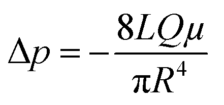
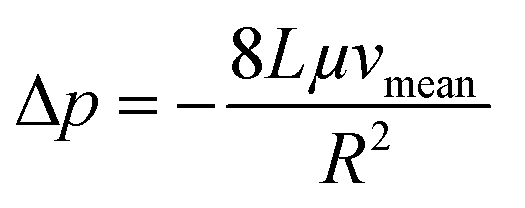
Next, we conducted a mathematical derivation of the convection-dominated TAD in order to gain an estimation for the consensus between theoretical and experimental values. Mathematically, the convection-mediated dilution can be described in circular tubing with Reynold numbers below 10. Under laminar flow conditions, the pressure drop in the tubing is expressed with the Hagen Poiseuille equation, where Δp equals the pressure difference between inlet and outlet, L the length of the tubing, Q the volumetric flow rate, μ the dynamic viscosity, and R the radius of the tubing (Fig. 4, eqn (2)).
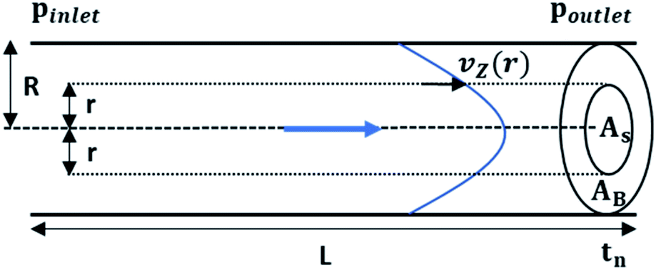 | ||
| Fig. 4 Schematic representation of convection mediated TAD in a tubing with length L and radius R. The parabolic distribution of the flow profile results from variations of flowrates (vz(r)) orthogonal to flow direction (r). With the flowrate distribution the cross-sectional area of the sample fluid (As) and the buffer (Ab) At can be calculated at given time tn. | ||
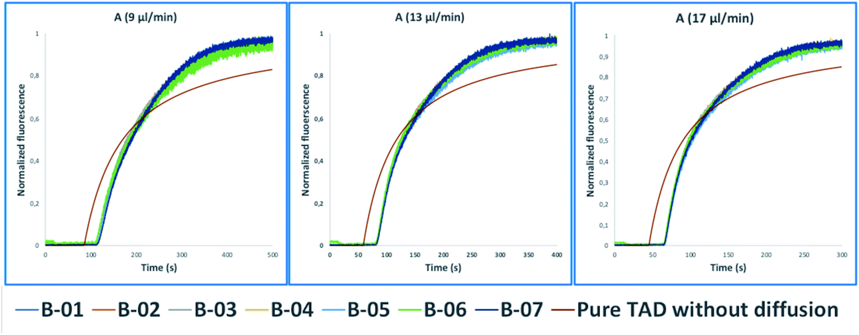 | ||
| Fig. 5 Normalized fluorescence spectra (y-axis) of the convection-dominated TAD in isopropanol of the BODIPY derivatives B-01 to B-07 (legend) in a 2.5 cm tubing with an inner diameter of 1 mm followed by a 1.5 cm tubing with an inner diameter 0.75 mm as a function of time in s (x-axis). The dilution curves of all seven compounds aligned perfectly at the three different flow rates evaluated: 9 μl min−1 (A), 13 μl min−1, and (C) 17 μl min−1. TAD without diffusion was calculated using eqn (5.1) for the two short capillaries (ID 1 mm, L 2.5 cm; ID 0.75 mm, L 1.5 cm) and the microfluidic channel of the chip (ID 0.04 mm, L 3 cm). Measurements for each compound were repeated in three technical replicates. | ||
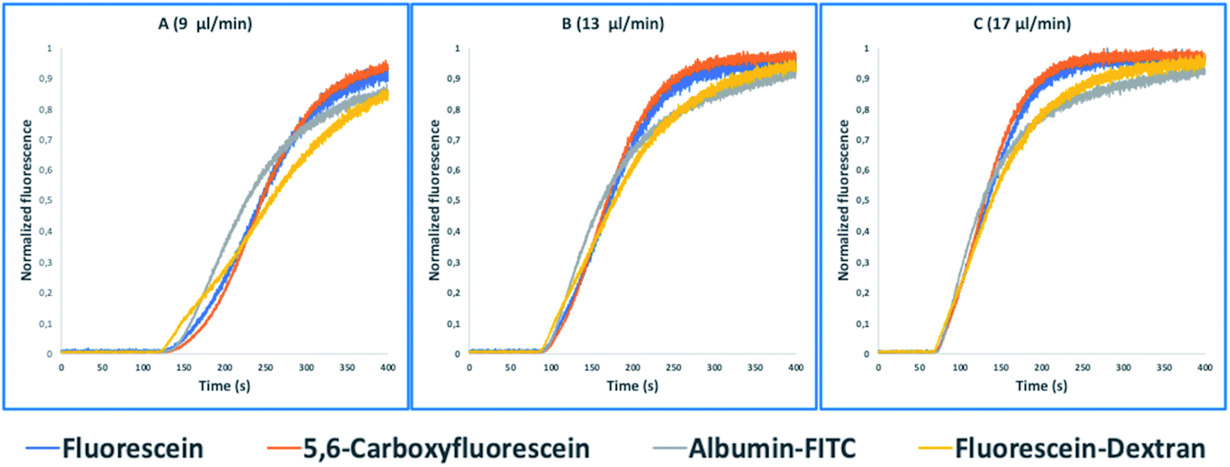 | ||
| Fig. 6 Normalized fluorescence spectra (y-axis) of the convection-dominated TAD in water of fluorescein (blue), 5,6-carboxyfluorescein (red), albumin-FITC (green), and fluorescein-dextran (purple) in a 2.5 cm tubing with an inner diameter 1 mm followed by a 1.5 cm tubing with an inner diameter of 0.75 mm as a function of time in s (x-axis). The dilution curves of all seven compounds showed an increasing alignment at the higher flow rates: 9 μl min−1 (A), 13 μl min−1, and 17 μl min−1. Measurements for each compound were repeated in three technical replicates. | ||
Eqn (2) is converted toeqn (2.1) by substituting Q with eqn (3).
 | (2) |
 | (2.1) |
| Q = vmeanπR2 | (3) |
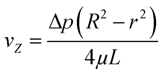
The radial velocity distribution vz under laminar flow in the cylindric channel is described by eqn (4), with r as the radial distance from the tube center orthogonally to the flow direction and p as the respective pressures (Fig. 4).
 | (4) |
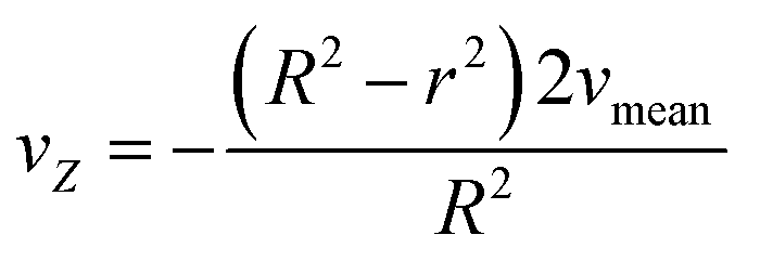
Solving eqn (2.1) and substituting it into eqn (4) results in eqn (4.1) describing the radial velocity distribution dependent on the difference to the center of the tubing.
 | (4.1) |
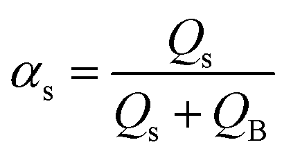
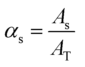
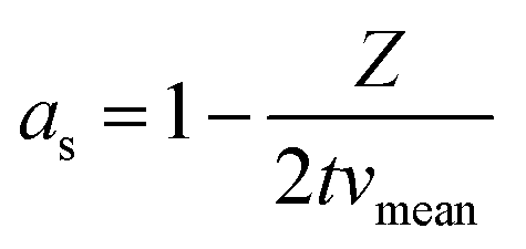
By the variation of time, a stepwise transition between a fluid phase S (sample) and phase B (pure buffer) is created. Regarding the composition of the mixture, this means that the fluid fraction αs varies between a percental ratio between 0 and 1 (eqn (5)).
 | (5) |
For the derivation of convection-dominated TAD, we start with the velocity distribution, which yields a particular velocity Z of the fluid at a distance r from the channel center. Please note the differences between flowrates dependent on the radial distance of the center vz(r) and the mean flowrates vmean. Since vz(r) is uniform, vz(r)/dz = 0. Therefore, we can substitute vz(r) by vz(r) = Z/t and solve the equation for r2:
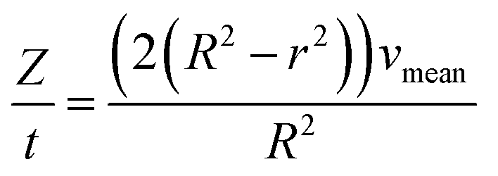 | (4.2) |
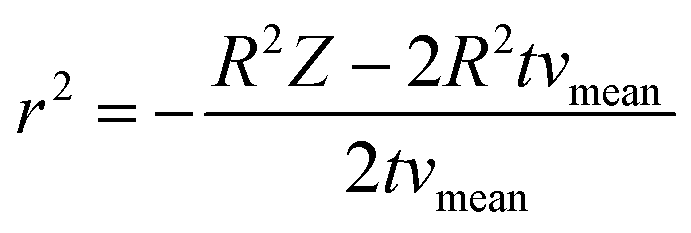 | (4.3) |
 | (5.1) |
After simplification, the final model for the pure Taylor dispersion without diffusion terms is obtained.
 | (6) |
During the simplification, the geometrical parameters are completely lost in the equation. Hence, the model is highly generic and depends only on the average fluid velocity, which can be easily calculated for a given channel from the flow rate and the channel cross-sectional area. The model yields negative values for 2 × t × vmean < Z, which can be substituted by zero.
In most microfluidic setups, the capillary of interest is connected to other capillaries or microreactors with varying inner diameters, leading to a further dispersion of compounds. Eqn (6) can be modified by substituting vmean for Q/A (eqn (3)), to account for the total TAD-mediated dispersion. The final equation was simplified to eqn. (6.1) and the hereby calculated values were compared to the measured BODIPY's dilution curves. As shown in Fig. 4 the experimental values were not only in high consensus with each other, but also showed a strong approximation to the theoretical value calculated using eqn (6.1) (Fig. 4, brown graph).
 | (6.1) |
High-resolution dose response curves for the determination of EC50 values
As described in the previous section, the high-resolution dose–response curves for the six reference compounds (Fig. 2) and the two in-house compounds (A and B) were measured at approximately 51 seconds post-mixing using convection-dominated TAD dilution.At maximal compound concentrations of 32 μM, only the CAM-A compounds BAY 41-4109 and GLS4 reached an assembly of 100%, while the other CAMs yielded lower assembly, ranging from 91% (compound B) to 58% (ABI-H0731) (Fig. 8). The resulting EC50 values were higher in comparison to the ones derived from microtiter plates, mainly due to the shorter measurement times and the different assay format (Fig. 7 and 8). Compounds with slower assembly kinetics showed significantly higher EC50 values due to the incomplete assembly reaction at this time point compared to the longer incubation times in the microtiter plate format. This was visualized by comparing the resulting dose–response curves, which show an exponential increase instead of a sigmoidal curve (Fig. 7). Measuring accurate EC50 values for “slower” CAMs could be performed at later time points, but the inhibition of further dilution due to TAD has to be prevented for comparative results.
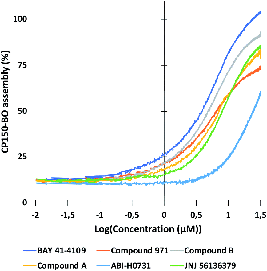 | ||
| Fig. 7 High-resolution dose–response curves for the six CAMs at 51 seconds post-mixing in flow. Compounds were diluted using TAD-mediated dispersion and mixed in flow as described in the Experimental section. CAM-N compounds had mostly incomplete CP150-BO assembly at 51 seconds, resulting in higher EC50 values. This was mainly evident for ABI-H0731, which yielded a non-sigmoidal assembly curve, due to the incomplete reaction. GLS4 and NVR 3-778 were measured at 10 μM maximal concentration due to solubility issues, and so, were not displayed in this graph. | ||
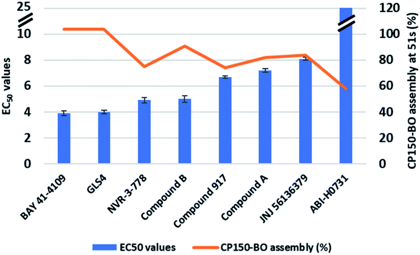 | ||
| Fig. 8 EC50 values of the six reference CAMs and the two in-house compounds in flow after 51 seconds. Each compound was tested at least two times. Interestingly, only the CAM-A compounds BAY 41-4109 and GLS4 reached 100% assembly, while the in-between CAM, compound B, resulted in a maximum assembly of 91%. Compounds with maximal CP150-BO assembly under 60% resulted in relatively higher EC50 values, due to the incomplete reaction. | ||
The assay presented here measured the EC50 values of several CAMs at early timepoints in an automated and reproducible manner. Information about the mode of action of the compounds was provided based on their assembly kinetics and is further elucidated in the following section.
CP150C assembly kinetics as an indicator of the mode of action of CAMs
As described in the introduction, capsid assembly is dependent on the buried hydrophobic interface between dimers, which regulates the strength of the interaction and consequently the assembly rate. Zhou et al. showed that HAPs could alter the buried interface between dimers, thereby strengthening the assembly reaction. In addition, HAPs could also change the probability of contact to spike domain, increasing the probability of aberrant structure formation.45 The fast assembly reaction due to high association energies, rapid nucleation, and assembly of aberrant structures, in turn, leads to the formation of kinetically trapped intermediates due to the depletion of free core protein.14Therefore, to distinguish between the modes of action of CAMs in this study, we opted to use the differences in the CAM-mediated CP150-BO assembly kinetics instead of the morphology of the resulting capsids and aggregates. Microfluidic systems fit these requirements perfectly, since they allow measurements after just a few seconds post-mixing, giving new insights about the reaction.
Using our microfluidic platform, we screened the assembly kinetics of six well-characterized reference inhibitors, two of which were categorized into CAM-A and four into CAM-N, as well as the two in-house compounds with unknown mode of action. The goal was to observe clear differences between the assembly kinetics of the known CAM-As compared to the CAM-Ns, and based on this data, to categorize the two in-house compounds. The reaction was performed in flow with 10-fold EC50 concentration of the compound obtained from the microtiter plate-based assay. Percentage assembly was calculated at several time points, ranging from 5 seconds up to 336 seconds (Fig. 9). Both CAM-A compounds led to a rapid assembly (GLS4: 99% assembly; BAY 41-4109: 82%) completed at 10 seconds post-mixing. On the other hand, CAM-N compounds showed variations in their respective kinetics and were categorized into two groups. “Slow” CAM-N led to an assembly of 6–18% at 7.5 seconds, while “fast” CAM-N compounds, such as compound B, NVR 3-778 and compound 917, were able to achieve assembly values between 44% to 61%. At the endpoint of 336 seconds, all the compounds reached an assembly of at least 88% with the highest values obtained by GLS4 (109%), BAY 41-4109 (100%), compound B (98%), JNJ-56136379 (92%) and compound A (94%). These tendencies showed that compounds with a CAM-A mode of action indeed have faster assembly kinetics, reaching slightly higher endpoint values in flow.
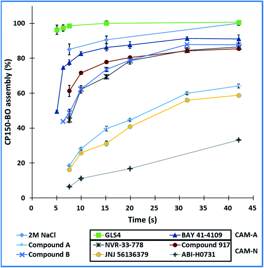 | ||
| Fig. 9 Kinetic development of the CP150-BO assembly reaction at various timepoints using the six references and the two inhouse compounds at 10-fold EC50 concentrations. The reactions were tested three times. | ||
To further study the impact of CAM concentration on capsid assembly kinetics and to facilitate the characterization of the mode of action of the two in-house compounds, measurements were conducted with 1, 10, and 100 μM CAMs. By using 1 μM CAM and a residence time of 2 minutes, CAM-A compounds and compound B reached approximately 40% assembly, while other compounds reached only around 29%. Increasing the concentration to 10 μM, while maintaining the same residence time of 2 minutes, led to a nearly complete assembly of approximately 95% for the CAM-As and 77% for compound B. Contrarily, the other compounds only reached maximal values ranging from 58% to 37%. Interestingly, significant differences in assembly between CAM-A (BAY 41-4109: 75%, GLS4: 89%) and the other compounds (31% to 2%) could be observed by reducing the residence time to 7.7 seconds, while maintaining a 10 μM concentration. Among the other compounds, compound B, NVR 3-778, and compound 917 achieved the highest assembly with approximately 27%. Finally, the CAM concentration was further increased to 100 μM with a residence time of 2 minutes, at which all the compounds reached an assembly of at least 75%. CAM-As again yielded the highest assembly rates at around 100%, followed by compound B at around 91%, and JNJ-56136379 at 87%. Measurement of the effect of 100 μM CAM at a shorter residence time of 7.7 s again displayed the difference between CAM-A (BAY 41-4109: 98%, GLS4: 92%) and CAM-N (around 65%) (Fig. 10). In summary, the reactions with 10 μM (or 32 μM as used in the EC50 measurements) CAMs were most appropriate to elucidate the difference between the two compound classes by eliminating oversaturation and, at the same time, maintaining a good signal to background ratios. Therefore, to accurately distinguish the CAMs'mode of action, we suggest using a 10 μM solution of the respective CAMs with 7.7 and 51 s as residence times, which led to the most apparent differentiation of the CAM's mode of action. At 7.7 s, CAM-A reached assembly values around 50% higher than CAM-N, and at 51 s, the assembly reaction for CAM-A was mostly completed contrary to CAM-N.
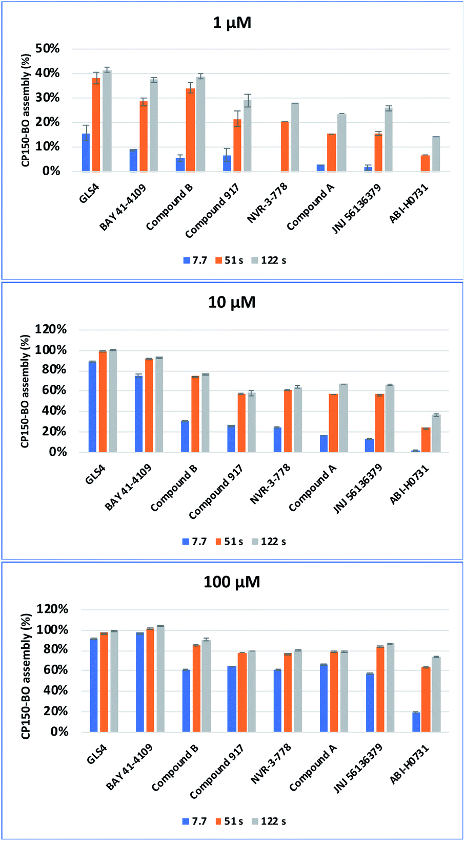 | ||
| Fig. 10 Cp150C assembly mediated by different CAMs at three different incubation time points (7.7 s, 51.1 s and 122.7 s) and in three concentrations (1 μM, 10 μM, 100 μM). For each compound, the reaction was performed in duplicate. | ||
Interestingly, while compound A behaved more like a classical “fast” CAM-N compound, compound B showed an in-between kinetic behavior at 1 μM and 10 μM concentrations, making a clear classification for this compound challenging. The difference of compound B to CAM-N was especially eye-catching at a concentration of 10 μM and 51 s at which both the other fast CAM-Ns compound 917 and NRV-33-778 showed a lower CP150-BO assembly rate. Consequently, size exclusion chromatography and immunofluorescence assays were conducted to further elucidate their modes of action.
Confirmation of the mode of action of screening compounds A and B in analytical size exclusion chromatography and immunofluorescence HBcAg staining
CAMs were reported to induce either the formation of morphologically intact, but empty HBV capsids (CAM-N) or larger aberrant structures (CAM-A). Analytical size exclusion chromatography is a well-established method of demonstrating CAM activity and differentiating between the two different modes of action18,46. In this work, compound A and compound B were incubated with CP150C for 2 h prior to separation on a Superose6 Increase column (Fig. 11). For each sample, two absorbance peaks were observed—one corresponding to the capsid, and the other to the core protein dimer. Mock treatment of CP150C with DMSO yielded low levels of capsid, as evidenced by the lower amplitude of the capsid peak compared to the dimer peak. On the other hand, as observed in previous studies, the incubation of CP150C with the CAM-A reference BAY 41-4109 induced the formation of larger structures, which eluted at an earlier retention volume compared to the capsid peak in the DMSO control (Δ retention volume ≤ −0.6 mL). In comparison, incubation of CP150C with known CAM-N compounds did not induce the formation of large, aberrant structures, with the capsid retention volume similar to the DMSO control (±0.2 mL) (data not shown). Comparing the SEC profiles obtained after incubation with compound A or B showed that compound B induced a shift of the capsid peak towards lower retention volumes, but not as drastic as that observed for BAY 41-4109. This shift indicates a possible tendency of compound B to a CAM-A mode of action. Conversely, although the capsid peak of compound A is not directly aligned with the DMSO control, it is still within the empirical Δ retention volume range of CAM-N compounds in the lab.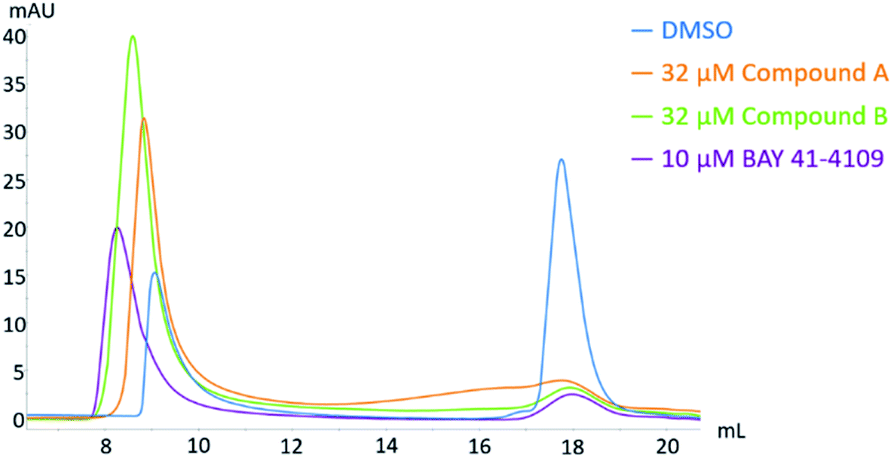 | ||
| Fig. 11 Analytical size exclusion chromatography of HBV capsid and core protein dimer after the exposure to different CAMs. Core protein CP150 was incubated in 60 mM BES, pH 6.8 with 150 mM NaCl and 10 or 32 μM CAM at 25 °C for 2 h prior to separation on a Superose6 Increase column. Two distinct peaks were observed, with the capsid peak (approximately 9 mL) eluting before the core protein dimer peak (approximately 18 mL). | ||
In addition to the biochemical analysis, the mode of action of compound A and B were analyzed in an antiviral assay using the immunostaining of HBcAg as a readout. In the HepG2.117 cell line, the expression of HBV is regulated by a tetracycline-responsive minimal CMV promoter. As shown in Fig. 12, HBV replication was repressed in cells treated with doxycycline, a second-generation tetracycline, whereas in DMSO-treated cells, HBcAg was detected in both the nucleus and the cytoplasm. As previously described, the HBcAg staining in cells treated with the CAM-N reference NVR 3-778 was almost exclusively found in the cytoplasm, whereas BAY 41-4109 which is known to follow the CAM-A mode of action, induced punctuated aggregates in or near the nucleus.18 In line with the observation from the SEC, treatment with compound A induced a CAM-N phenotype, whereas treatment with compound B had the tendency to induce aggregated dot-like structures exclusively seen after CAM-A treatment. However, the number and size of these aggregates were significantly lower than in BAY 41-4109-treated cells.
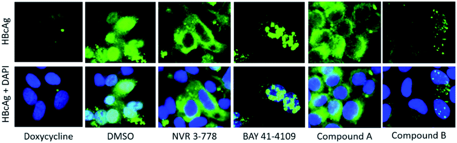 | ||
| Fig. 12 Immunofluorescence staining of HBcAg in HepG2.117 cells after treatment with different CAMs. Cells were cultured without doxycycline to induce HBV expression, and treated with either DMSO, 50-fold EC50 of NVR 3-778, BAY 41-4109, compound A, or compound B for 6 days. HBcAg was visualized via indirect immunofluorescence staining using an anti-HBcAg antibody (green). In the lower panels, nuclei were counterstained with DAPI (blue) and the images of both stains were merged. In doxycycline treated cells, HBV replication was repressed. | ||
From these results, we classify compound A as having a classical CAM-N mode of action. On the other hand, this study showed evidence in all three experiments, namely the kinetics analysis using the microfluidic system, the SEC, and the immunostaining of HBcAg in HepG2.117 cells, that compound B displays a profile which is similar but weaker to that of the CAM-A reference compound.
Hence, the aggressive assembly displayed by CAM-A compounds is a possible identification factor for the mode of action of different CAMs. Evidently, the microfluidics platform offers an excellent opportunity for further study of capsid kinetics, as well as the differentiation of the modes of action of CAMs in a rapid and reliable manner.
Conclusions
In this paper, we have developed a fully automated microfluidic system mainly obtained from commercially available modular components allowing other research groups the simple reproduction of the obtained data, the extension of the system with further modules, and adaptation of the setup to different assay formats and tasks. With this system, the convection-mediated, unilateral TAD was evaluated both mathematically and experimentally. The obtained dilution curves were utilized to generate high-dose response curves for the HBc capsid assembly assay and calculate respective EC50 values inflow at 51 seconds post-mixing, unlike the microtiter-based assay formats (which require more time – from 5 minutes up to days). Due to the lower measurement time and differences in the assay format, the in-flow measured values were higher than those measured in microtiter format with EC50 around 3–4 μM for compounds with faster assembly rates. Following the activity evaluation, the HBV capsid assembly was measured at early kinetics of down to five seconds for the first time with six well-characterized reference CAMs and two in-house compounds in the early drug discovery research stage. At concentrations of 10-fold EC50 values, both CAM-A compounds BAY 41-4109 and GLS4 displayed a rapid assembly unmatched by the other CAMs. Furthermore, at higher residence times, these compounds led to a higher overall CP150-BO assembly of 100% compared to CAM-N compounds with maximal assemblies around 60–84% inflow. The concentration-dependent kinetics were measured in a second experiment using three different stock concentrations (1 μM, 10 μM, and 100 μM). CAM-A compounds were significantly faster than CAM-N at all three concentrations, with especially profound differences at the lower residence times of 7.7 s.Interestingly, the in-house compound B showed faster and higher maximal assemblies compared to other CAM-Ns, particularly at a concentration of 10 μM and residence times of 7.7 and 51 s but was not quite reaching the levels of the other CAM-As. This compound showcased similar in-between behavior in the immunofluorescence assay and SEC as well. Therefore, we conclude that aside from the morphology of the assembled products and the localization in cells, the aggressive assembly displayed by CAM-A compounds is a possible identification factor for the mode of action of different CAMs. In conclusion, the microfluidic system offers a valuable opportunity to rapidly screen for novel CAMs. It provides information about the activity and kinetics of compounds simultaneously, also giving a first hint about the mode of action of novel CAMs. Furthermore, with the evaluation of the kinetic data at three independent time points (7.7, 51, and 122 s), the differentiation of mode of action per compound is possible within 4 min, as opposed to the analytical size exclusion chromatography requiring at least 3 h for sample preparation and evaluation. Finally, the possibility of measuring reactions at a couple of seconds provides an excellent opportunity to study capsid kinetics and further novel viral or bacterial targets.
Author contributions
Tamás Vermes: writing – original draft, conceptualization, software, formal analysis, data curation, investigation, visualization, validation, methodology, Thomas Henkel: formal analysis, resources, Mark Kielpinski: formal analysis, resources, Miquel A. Pericàs: conceptualization, resources, funding acquisition, supervision, Esther Alza: conceptualization, resources, project administration, funding acquisition, supervision, Angelica Corcuera: writing – review & editing, visualization, methodology, investigation, Helmut Buschmann: conceptualization, resources, funding acquisition, supervision. Thomas Goldner: conceptualization, project administration, funding acquisition, supervision. Andreas Urban: writing – original draft, conceptualization, supervision, investigation.Conflicts of interest
There are no conflicts to declare.Acknowledgements
The authors gratefully acknowledge the excellent technical assistance of Wiebke Schultze, Ilva Leckebusch, and Lucas Grebe. We would also like to thank the Fluigent team from Jena, Germany for their excellent support. The project VIRO-FLOW has received funding from the European Union's Horizon 2020 research and innovation program under grant agreement No. 766058.Notes and references
- M. Hay, D. W. Thomas, J. L. Craighead, C. Economides and J. Rosenthal, Nat. Biotechnol., 2014, 32, 40–51 CrossRef CAS PubMed.
- A. D. Hingorani, V. Kuan, C. Finan, F. A. Kruger, A. Gaulton, S. Chopade, R. Sofat, R. J. MacAllister, J. P. Overington, H. Hemingway, S. Denaxas, D. Prieto and J. P. Casas, Sci. Rep., 2019, 9, 1–25 Search PubMed.
- A. K. Ghosh, M. Brindisi, D. Shahabi, M. E. Chapman and A. D. Mesecar, ChemMedChem, 2020, 15, 907–932 CrossRef CAS PubMed.
- S. A. P. Pereira, P. J. Dyson and M. L. M. F. S. Saraiva, TrAC, Trends Anal. Chem., 2020, 126, 115862 CrossRef CAS.
- G. M. Whitesides, Nature, 2006, 442, 368–373 CrossRef CAS PubMed.
- D. Măriuţa, S. Colin, C. Barrot-Lattes, S. Le Calvé, J. G. Korvink, L. Baldas and J. J. Brandner, Microfluid. Nanofluid., 2020, 24 Search PubMed.
- P. S. Dittrich and A. Manz, Anal. Bioanal. Chem., 2005, 382, 1771–1782 CrossRef CAS PubMed.
- G. Nys and M. Fillet, J. Pharm. Biomed. Anal., 2018, 159, 348–362 CrossRef CAS PubMed.
- B. Hepatitis, https://www.who.int/news-room/fact-sheets/detail/hepatitis-b, accessed 20 May 2021.
- A. Zlotnick, B. Venkatakrishnan, Z. Tan, E. Lewellyn, W. Turner and S. Francis, Antiviral Res., 2015, 121, 82–93 CrossRef CAS PubMed.
- A. Diab, A. Foca, F. Zoulim, D. Durantel and O. Andrisani, Antiviral Res., 2018, 149, 211–220 CrossRef CAS PubMed.
- B. Böttcher, S. A. Wynne and R. A. Crowther, Nature, 1997, 386, 88–91 CrossRef PubMed.
- P. Ceres and A. Zlotnick, Biochemistry, 2002, 41, 11525–11531 CrossRef CAS PubMed.
- A. Zlotnick, J. M. Johnson, P. W. Wingfield, S. J. Stahl and D. Endres, Biochemistry, 1999, 38, 14644–14652 CrossRef CAS PubMed.
- S. Katen and A. Zlotnick, Chapter 14 The Thermodynamics of Virus Capsid Assembly, Elsevier Inc., 1st edn, 2009, vol. 455 Search PubMed.
- C. A. Lutomski, N. A. Lyktey, E. E. Pierson, Z. Zhao, A. Zlotnick and M. F. Jarrold, J. Am. Chem. Soc., 2018, 140, 5784–5790 CrossRef CAS PubMed.
- S. Wang, M. L. Fogeron, M. Schledorn, M. Dujardin, S. Penzel, D. Burdette, J. M. Berke, M. Nassal, L. Lecoq, B. H. Meier and A. Böckmann, Front. Mol. Biosci., 2019, 6, 1–11 CrossRef CAS PubMed.
- A. Corcuera, K. Stolle, S. Hillmer, S. Seitz, J. Y. Lee, R. Bartenschlager, A. Birkmann and A. Urban, Antiviral Res., 2018, 158, 135–142 CrossRef CAS PubMed.
- S. P. Katen, S. R. Chirapu, M. G. Finn and A. Zlotnick, ACS Chem. Biol., 2010, 5, 1125–1136 CrossRef CAS PubMed.
- J. M. Berke, P. Dehertogh, K. Vergauwen, E. Van Damme, W. Mostmans, K. Vandyck and F. Pauwels, Antimicrob. Agents Chemother., 2017, 61, 1–14 CrossRef PubMed.
- S. J. Stray, C. R. Bourne, S. Punna, W. G. Lewis, M. G. Finn and A. Zlotnick, Proc. Natl. Acad. Sci. U. S. A., 2005, 102, 8138–8143 CrossRef CAS PubMed.
- Z. Zhou, T. Hu, X. Zhou, S. Wildum, F. Garcia-Alcalde, Z. Xu, D. Wu, Y. Mao, X. Tian, Y. Zhou, F. Shen, Z. Zhang, G. Tang, I. Najera, G. Yang, H. C. Shen, J. A. T. Young and N. Qin, Sci. Rep., 2017, 7, 1–12 CrossRef PubMed.
- H. R.-W. Karl Deres, Science, 2003, 303, 1829 Search PubMed.
- E. P. Tsounis, E. Tourkochristou, A. Mouzaki and C. Triantos, World J. Gastroenterol., 2021, 21, 2727–2757 CrossRef PubMed.
- A. Zlotnick, A. Lee, C. R. Bourne, J. M. Johnson, P. L. Domanico and S. J. Stray, Nat. Protoc., 2007, 2, 490–498 CrossRef CAS PubMed.
- M. Newman, F.-M. Suk, M. Cajimat, P. K. Chua and C. Shih, J. Virol., 2003, 77, 12950–12960 CrossRef CAS PubMed.
- A. Zlotnick, R. Aldrich, J. M. Johnson, P. Ceres and M. J. Young, Virology, 2000, 277, 450–456 CrossRef CAS PubMed.
- S. Sauviller, K. Vergauwen, S. Jaensch, E. Gustin, D. Peeters, P. Vermeulen, D. Wuyts, K. Vandyck, F. Pauwels and J. M. Berke, J. Virol. Methods, 2021, 293, 114150 CrossRef CAS PubMed.
- G. Tresset, C. Le Coeur, J. F. Bryche, M. Tatou, M. Zeghal, A. Charpilienne, D. Poncet, D. Constantin and S. Bressanelli, J. Am. Chem. Soc., 2013, 135, 15373–15381 CrossRef CAS PubMed.
- C. Uetrecht, I. M. Barbu, G. K. Shoemaker, E. Van Duijn and A. J. R. Heck, Nat. Chem., 2011, 3, 126–132 CrossRef CAS PubMed.
- A. Borodavka, R. Tuma and P. G. Stockley, Proc. Natl. Acad. Sci. U. S. A., 2012, 109, 15769–15774 CrossRef CAS PubMed.
- J. Zhou, P. Kondylis, D. G. Haywood, Z. D. Harms, L. S. Lee, A. Zlotnick and S. C. Jacobson, Anal. Chem., 2018, 90, 7267–7274 CrossRef CAS PubMed.
- Z. D. Harms, L. Selzer, A. Zlotnick and S. C. Jacobson, ACS Nano, 2015, 9, 9087–9096 CrossRef CAS PubMed.
- P. Kondylis, J. Zhou, Z. D. Harms, A. R. Kneller, L. S. Lee, A. Zlotnick and S. C. Jacobson, Anal. Chem., 2017, 89, 4855–4862 CrossRef CAS PubMed.
- P. Kondylis, C. J. Schlicksup, N. E. Brunk, J. Zhou, A. Zlotnick and S. C. Jacobson, J. Am. Chem. Soc., 2019, 141, 1251–1260 CrossRef CAS PubMed.
- M. Thiele, A. Knauer, A. Csáki, D. Mallsch, T. Henkel, J. M. Köhler and W. Fritzsche, Chem. Eng. Technol., 2015, 38, 1131–1137 CrossRef CAS.
- L. A. Currie, Anal. Chem., 1968, 40, 586–593 CrossRef CAS.
- J.-H. Zhang, T. D. Y. Chung and K. R. Oldenburg, J. Biomol. Screening, 1999, 4, 67–73 CrossRef PubMed.
- D. Sun and M. Nassal, J. Hepatol., 2006, 45, 636–645 CrossRef CAS PubMed.
- B. J. Kirby, Micro- and Nanoscale Fluid Mechanics, CAMBRIDGE UNIVERSITY PRESS, 2010 Search PubMed.
- M. Werner, C. Kuratli, R. E. Martin, R. Hochstrasser, D. Wechsler, T. Enderle, A. I. Alanine and H. Vogel, Angew. Chem., Int. Ed., 2014, 53, 1704–1708 CrossRef CAS PubMed.
- O. J. Miller, A. El Harrak, T. Mangeat, J.-C. Baret, L. Frenz, B. El Debs, E. Mayot, M. L. Samuels, E. K. Rooney, P. Dieu, M. Galvan, D. R. Link and A. D. Griffiths, Proc. Natl. Acad. Sci. U. S. A., 2012, 109, 378–383 CrossRef CAS PubMed.
- S. S. Terekhov, I. V. Smirnov, A. V. Stepanova, T. V. Bobik, Y. A. Mokrushina, N. A. Ponomarenko, A. A. Belogurov, M. P. Rubtsova, O. V. Kartseva, M. O. Gomzikova, A. A. Moskovtsev, A. S. Bukatin, M. V. Dubina, E. S. Kostryukova, V. V. Babenko, M. T. Vakhitova, A. I. Manolov, M. V. Malakhova, M. A. Kornienko, A. V. Tyakht, A. A. Vanyushkina, E. N. Ilina, P. Masson, A. G. Gabibov and S. Altman, Proc. Natl. Acad. Sci. U. S. A., 2017, 114, 2550–2555 CrossRef CAS PubMed.
- L. F. Cai, Y. Zhu, G. S. Du and Q. Fang, Anal. Chem., 2012, 84, 446–452 CrossRef CAS PubMed.
- Z. Zhou, T. Hu, X. Zhou, S. Wildum, F. Garcia-Alcalde, Z. Xu, D. Wu, Y. Mao, X. Tian, Y. Zhou, F. Shen, Z. Zhang, G. Tang, I. Najera, G. Yang, H. C. Shen, J. A. T. Young and N. Qin, Sci. Rep., 2017, 7, 1–12 CrossRef PubMed.
- A. Zlotnick and S. Katen, Methods Enzymol., 2009, 6879, 1–19 Search PubMed.
- G. D. Hartman, S. Kuduk, Derivatives and methods of treating Hepatitis B infections, Novira Therapeutics Inc., World patent, WO2016/109689A2, 2016 July 7 Search PubMed.
- J. M. Berke, P. Dehertogh, K. Vergauwen, W. Mostmans, K. Vandyck, P. Raboisson and F. Pauwels, Antimicrob. Agents Chemother., 2020, 64(5) DOI:10.1128/aac.02439-19.
- Q. Huang, D. Cai, R. Yan, L. Li, Y. Zong, L. Guo, A. Mercier, Y. Zhou, A. Tang, K. Henne and R. Colonno, Antimicrob. Agents Chemother., 2020, 64(11) DOI:10.1128/aac.01463-20.
- A. M. Lam, C. Espiritu, R. Vogel, S. Ren, V. Lau, M. Kelly, S. D. Kuduk, G. D. Hartman, O. A. Flores and K. Klumpp, Antimicrob. Agents Chemother., 2019, 63(1) DOI:10.1128/aac.01734-18.
- X.-Y. Wang, Z.-M. Wei, G.-Y. Wu, J.-H. Wang, Y.-J. Zhang, J. Li, H.-H. Zhang, X.-W. Xie, X. Wang, Z.-H. Wang, L. Wei, Y. Wang and H.-S. Chen, Antiviral Ther., 2012, 17(5), 793–803 CrossRef CAS PubMed.
Footnote |
| † Electronic supplementary information (ESI) available. See DOI: 10.1039/d1ay01227d |
| This journal is © The Royal Society of Chemistry 2022 |