
 Open Access Article
 This Open Access Article is licensed under a Creative Commons Attribution-Non Commercial 3.0 Unported Licence
Large enhancement of ferroelectric polarization in Hf0.5Zr0.5O2 films by low plasma energy pulsed laser deposition†
Tingfeng
Song
,
Raul
Solanas
,
Mengdi
Qian
,
Ignasi
Fina
* and
Florencio
Sánchez
 *
*
Institut de Ciència de Materials de Barcelona (ICMAB-CSIC), Campus UAB, Bellaterra 08193, Barcelona, Spain. E-mail: ifina@icmab.es; fsanchez@icmab.es
First published on 7th December 2021
Abstract
The ferroelectric phase of HfO2 is generally stabilized in polycrystalline films, which typically exhibit the highest polarization when deposited using low oxidizing conditions. In contrast, epitaxial films grown by pulsed laser deposition show low or suppressed polarization if a low oxygen pressure is used. Epitaxial films are essential to better understand physical properties, and obtaining films that have intrinsic polarization is of great importance. In order to advance towards this objective, we have carried out a systematic study of the epitaxial growth of Hf0.5Zr0.5O2 combining inert Ar gas with oxidizing O2 gas. This allows us to control the oxidizing conditions (through O2 partial pressure) and the energy of the pulsed laser deposition plasma (through the total pressure of O2 and Ar). A pressure of Ar high enough to significantly reduce plasma energy and that of O2 low enough to reduce oxidation conditions are found to allow a large increase in ferroelectric polarization up to about 30 μC cm−2, representing an increase of around 50% compared to films grown by conventional pulsed laser deposition. This simple growth process, with high impact in the development of ferroelectric HfO2, can be also beneficial in the growth of thin films of other materials by pulsed laser deposition.
1. Introduction
The discovery of robust ferroelectricity in a metastable orthorhombic phase of HfO2,1 a material compatible with CMOS processes, has generated enormous scientific interest and great expectations for commercial applications. HfO2 is monoclinic (paraelectric) in bulk, but an orthorhombic phase (ferroelectric) can be stabilized at room temperature in doped HfO2 thin films.2,3 The stabilization of this phase has been achieved using different chemical and physical deposition techniques, being atomic layer deposition (ALD) the most widely used among them. The oxidizing conditions during HfO2 growth are crucial to stabilize the ferroelectric phase. Pal et al.4 observed an increase in ferroelectric polarization with decreasing the duration of the ALD ozone pulses. This also caused a large increase in the leakage current, which pointed to a high concentration of oxygen vacancies. Materano et al.5 reported a higher amount of orthorhombic phase and larger polarization in HfO2 and Hf0.5Zr0.5O2 (HZO) films grown by ALD when the O3 dose was lowered. This dependence is not observed in the case of pure ZrO2 films.5,6 Among the physical deposition techniques, sputtering is most commonly used to grow polycrystalline doped HfO2 films. The technique is based on an Ar plasma that sputters a solid target, and a mixed O2/Ar atmosphere is typically needed to grow thin films of most oxides. However, the O2 atmosphere does not favor the stabilization of the metastable ferroelectric phase of HfO2, and pure Ar or low O2 flow conditions are needed. For example, HZO films showed the highest polarization when sputtering was carried out under pure Ar.7 In the case of undoped HfO2 films, sputtering under a low oxygen flow helps to stabilize the orthorhombic phase.5 Recently, Mittmann et al.8,9 reported that a high oxygen flow favors the formation of the paraelectric monoclinic phase in the entire composition range of HfO2–ZrO2, and a low flow was needed to suppress the formation of the tetragonal phase. The reported results, as a whole, indicate that HfO2-based polycrystalline films, deposited by chemical or physical methods, present a greater amount of ferroelectric orthorhombic phase when low oxidizing conditions are used.10,11 The experimental results are in agreement with theoretical calculations of the reduced energy difference between the metastable orthorhombic phase and the stable monoclinic phase when HfO2 contains oxygen vacancies.12Ferroelectric HfO2 epitaxial films are generally grown by pulsed laser deposition (PLD).13–17 The technique, unlike sputtering, does not require the use of Ar gas and an atmosphere of pure O2 is commonly used. Lyu et al.16,18 reported the growth window of ferroelectric epitaxial HZO by PLD. HZO crystallizes at temperature and oxygen pressure (PO2) greater than about 700 °C and 0.02 mbar, respectively.16 The amount of orthorhombic phase increases with PO2, the maximum PO2 ranges from 0.08 to 0.2 mbar (the highest pressure used in the experiments).16 The ferroelectric polarization exhibits the same dependence on PO2, confirming that a low oxidizing atmosphere during PLD suppresses the formation of the orthorhombic phase. Regarding leakage current, it is important to note that it decreases with increasing ferroelectric polarization. Therefore, the influence of oxidizing conditions in PLD is the opposite to that in chemical methods or sputtering. On the other hand, ferroelectric doped-HfO2 epitaxial films have been also prepared by solid phase epitaxy using sputtering, and the films deposited under pure Ar showed much better ferroelectric properties than the films deposited under a mixed Ar/O2 atmosphere.19 Therefore, epitaxial and polycrystalline films show the same dependence on oxidizing conditions when the same deposition method is used. Consequently, the inhibition of ferroelectric phase formation under low oxidizing conditions is specific to films grown by the PLD technique.
The oxygen pressure in a PLD process has an obvious effect on the oxidation of the films. It affects the amount of oxygen vacancies and the phase formed in the case of competing valence states (in FexOy films, for example). The oxygen content in the film will depend, besides the oxygen pressure in the PLD chamber, on the substrate temperature because of the high vapor pressure of oxygen. But the oxygen pressure during PLD is also critical because the material ablated with each laser pulse interacts with the oxygen gas.20,21 The ablated atoms constitute a very high-energy plasma, the so-called PLD plume, which propagates along the normal direction of the target. When the ablation process occurs in the presence of a background gas, the interaction with the gas atoms reduces the kinetic energy of the ablated species. As the background pressure increases, the plasma energy decreases. The plume scattering also causes a decrease in the growth rate and can produce off-stoichiometry in the case of multi-cation films.22–24 The kinetic energy of the emitted atoms, which also depends on the laser fluence, can reach tens of eV under low pressure conditions.25 The effect of the high-energy atoms on the film can be dramatic, reducing the crystallization26,27 and even causing self-sputtering in the film.28–30 On the other hand, if the ambient pressure is high enough to thermalize the PLD plasma, the crystallinity of the films also degrades.27 Therefore, the gas (pressure and composition) during PLD needs to be optimized. These effects must be considered, if a low oxygen pressure is used to decrease oxidation conditions, in order to favor the formation of a particular phase.
A method of reducing the plasma energy without increasing the film oxidation is introducing an inert gas during the PLD process. PLD under an inert gas was scarcely done in the past.28,29,31,32 Recently, it has been used successfully to obtain transparent conducting SrVO3 films without spurious phases.33,34 An inert gas can be also necessary to deposit oxide films on highly reactive substrates. For example, pure Ar gas was used to grow HZO films on bare Si.35 Here, we combine O2 and Ar as ambient gas to grow HZO ferroelectric films by PLD under low oxidation conditions and reduced plasma energy. This allows extending the growth window of epitaxial HZO to lower oxygen pressure without epitaxy degradation caused by an excessively energetic plasma. We show that a low plasma energy allows the increase of ferroelectric polarization in epitaxial HZO films by more than 50% with respect to equivalent films prepared by conventional PLD. The polarization values match well with the theoretically calculated polarization for the ferroelectric Pca21 orthorhombic phase of HfO2. Low plasma energy processes could be also used to prepare conventional (perovskites) or unconventional (as ε-Fe2O3 or Al1−xScxN) ferroelectrics with improved properties.
2. Experimental
HZO films were grown on SrTiO3(001) (STO) substrates buffered with a La0.67Sr0.33MnO3 (LSMO) electrode of ∼25 nm thickness. The ferroelectric HZO film and the LSMO electrode were deposited via a single process by PLD using a KrF excimer laser. LSMO electrodes were deposited at a substrate temperature of 700 °C under 0.1 mbar of oxygen. HZO films were deposited at 800 °C under an Ar/O2 atmosphere. Three series of films were grown by varying the Ar pressure (PAr) with fixed O2 pressure (PO2) values of 0.01 mbar, 0.05 mbar and 0.1 mbar, and four series by varying PO2 with fixed PAr of 0 mbar, 0.05 mbar, 0.1 mbar and 0.2 mbar. Sketches in Fig. S1 (ESI†) summarize the PAr/PO2 values in these series. HZO films were deposited with 800 laser pulses, and immediately after growth, the samples were cooled under 0.2 mbar of oxygen. Structural characterization was performed by X-ray diffraction (XRD) using Cu Kα radiation. Circular platinum top electrodes (thickness: 20 nm and diameter: 20 μm) were deposited by dc magnetron sputtering through stencil masks for electrical characterization. Ferroelectric polarization loops at a frequency of 1 kHz and leakage current were measured in the top-bottom configuration (grounding the bottom electrode and biasing the top one) at room temperature using an AixACCT TFAnalyser2000 platform. Maximum electric field before the sample breakdown was applied for all the samples. Leakage contribution to the polarization loops was minimized using the dynamic leakage current compensation (DLCC) procedure.3. Results
Fig. 1a shows the XRD θ–2θ scans of the films deposited under a mixed Ar/O2 atmosphere (partial PO2 = 0.01 mbar is fixed and partial PAr is varied, thus varying the total atmospheric pressure). The XRD θ–2θ scans are zoomed around the position of the orthorhombic (o)-HZO(111) reflections (wider 2θ range scans of all samples are presented in Fig. S2, ESI†). The film deposited without Ar, i.e. under pure PO2 = 0 mbar (black line), is not crystallized, in agreement with the reported growth window for conventional PLD.16 In contrast, the films deposited under a mixed Ar/O2 atmosphere exhibit a diffraction peak at the position of the o-HZO(111) reflection (2θ ∼ 30°) and a less intense peak at 2θ ∼ 34° which corresponds to a {200} reflection of the monoclinic (m) phase. The intensity of the o-HZO(111) peak is low in the PAr = 0.01 mbar and 0.02 mbar samples (red and blue lines, respectively) and high in the PAr = 0.05 mbar and 0.1 mbar samples (green and purple lines, respectively). Laue oscillations around the o-HZO(111) peak are evident in the PAr = 0.1 mbar film. The thickness of this film, determined by simulation of the Laue fringes (Fig. S3, ESI†), is 7.7 nm. A higher Ar pressure (0.2 mbar, gold line) results in a less intense and broader o-HZO(111) peak. The width of the peak signals that the film is thinner (t ∼ 5.9 nm), which is a consequence of the scattering of Hf and Zr atoms by the higher pressure (the dependence of the growth rate with PAr is shown in Fig. S4, ESI†). In summary, Fig. 1a shows that PAr = 0.05–0.1 mbar is optimal to stabilize the orthorhombic phase with a very low PO2 of 0.01 mbar. Next, we show in Fig. 1b and c the effect of PO2 when PAr is fixed at 0.05 mbar and 0.1 mbar, respectively. In the PAr = 0.05 mbar series (Fig. 1b), the oxygen pressure threshold for crystallization is around PO2 = 5 × 10⁻³ mbar (red line). The film grown under this PO2 partial pressure shows low intensity o-(111) and m-{200} peaks. The intensity of the o-(111) peak increases notably in the films deposited under higher PO2, and Laue oscillations are evident in the PO2 = 0.02 and 0.05 mbar films. The pole figures measured in the PO2 = 0.05 mbar film (Fig. S5, ESI†) confirm the epitaxial ordering of the orthorhombic phase. There are twelve poles, signaling the presence of four families of crystal variants, as reported for the equivalent films grown under a pure O2 atmosphere.14,16 The PO2 = 0.1 mbar film (gold line), which is thinner due to the reduced growth rate caused by plasma scattering, also shows evident Laue fringes. In the PAr = 0.1 mbar series (Fig. 1c), there is crystallization even in the film deposited without oxygen partial pressure. The XRD scan of the PO2 = 0 mbar film (black line) presents o-(111) and m-{200} diffraction peaks. The intensity of the o-(111) peak increases significantly in the film grown under PO2 = 2 × 10⁻³ mbar (red line), and it is very intense and accompanied by Laue fringes in the PO2 = 5 × 10⁻³ mbar (blue line) and 0.01 mbar (green line) films. The films deposited under higher PO2 are also orthorhombic, and a significant thickness decrease is observed in the PO2 = 0.1 mbar film (turquoise line). | ||
| Fig. 1 XRD θ–2θ scans of films deposited under a mixed Ar/O2 atmosphere. (a) Fixed PO2 = 0.01 mbar and varying PAr. The scan corresponding to PAr = 0 mbar and PO2 = 0.01 mbar has been reported in ref. 16. (b) Fixed PAr = 0.05 mbar and varying PO2. (c) Fixed PAr = 0.1 mbar and varying PO2. | ||
The intensity of the o-(111) reflection allows the quantification of the dependence of the amount of orthorhombic phase on the O2 and Ar partial pressure (Fig. 2). There are no significant differences if normalization is performed with the STO(002) substrate peak (Fig. S6, ESI†). IHZO(111)/ILSMO(002) increases with PO2 (Fig. 2a), with little additional effect of the Ar pressure when PO2 is high. The crystallization is very low in films grown under a pure oxygen pressure lower than 0.05 mbar, but in the presence of additional Ar the stabilization of the orthorhombic phase is greatly enhanced. The amount of orthorhombic phase is slightly underestimated in the two PAr = 0.2 mbar films due to their lower thickness, but the equivalent graphs normalized to the film thickness exhibit the same relation (Fig. S7, ESI†). The dependence of IHZO(111)/ILSMO(002) on PAr (Fig. 2b) evidences that, under a high PAr pressure (0.1 or 0.2 mbar), the amount of orthorhombic phase only depends slightly on PO2. In brief, the presence of Ar notably enhances the stabilization of the o-phase for a low PO2 (up to about 0.05 mbar) and does not cause a significant effect for a higher PO2.
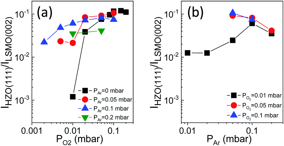 | ||
| Fig. 2 Intensity of the o-(111) reflection, normalized to that of the LSMO(002) peak, IHZO(111)/ILSMO(002), as a function of PO2 (a) and PAr (b). In (a) PAr is 0 mbar (black squares), 0.05 mbar (red circles), 0.1 mbar (blue up-pointing triangles), and 0.2 mbar (green down-pointing triangles). Data corresponding to PAr = 0 mbar are reported in ref. 16. In (b) PO2 is 0.01 mbar (black squares), 0.05 mbar (red circles), and 0.1 mbar (blue up-pointing triangles). | ||
The out-of-plane lattice parameter associated with the HZO(111) reflection, dHZO(111), was determined from the peak position. The dependences of dHZO(111) on PO2 and PAr are shown in Fig. 3a and b, respectively. The dHZO(111) value expands by decreasing PO2 (Fig. 3a). On the other hand, dHZO(111) of the films deposited at PO2 below around 0.05 mbar depends on PAr, with dHZO(111) less expanded for a high Ar pressure. The effect of PAr can be directly visualized in Fig. 3b. The lattice parameter of the films deposited under PO2 = 0.01 mbar (black squares) decrease with increasing PAr up to 0.1 mbar. The plasma is thermalized for a higher PAr and dHZO(111) does not change with PAr or PO2. To rationalize the intriguing dependence of dHZO(111) on PAr and PO2 shown in Fig. 3a and b, two causes of cell expansion have to be considered. On one hand, a higher number of oxygen vacancies is expected as PO2 is lower. On the other hand, other point defects can be formed if the PLD plasma has a high energy, which happens when the total pressure, PAr + PO2, is low. Indeed, deposition under high-energy PLD plasma (low PAr and low PO2) reduces strongly the film crystallization (Fig. 1 and 2). Thus, a high oxygen pressure is required to avoid film degradation if PAr is low. This implies that low oxidation conditions cannot be used to grow HfO2 films when the films are grown using a pure O2 atmosphere. Thus, conventional PLD does not permit growth conditions closer to those that result in the largest ferroelectric polarization when ALD or sputtering is used (low oxidizing conditions).11 However, as demonstrated here, the use of inert Ar gas to reduce the PLD plasma energy allows the stabilization of the orthorhombic phase with around one order of magnitude lower PO2 (0.01 mbar) than the optimal pressure (0.1 mbar) in conventional PLD (Fig. 2) and importantly reduces the number of defects (signaled by the d(111) expansion, Fig. 3).
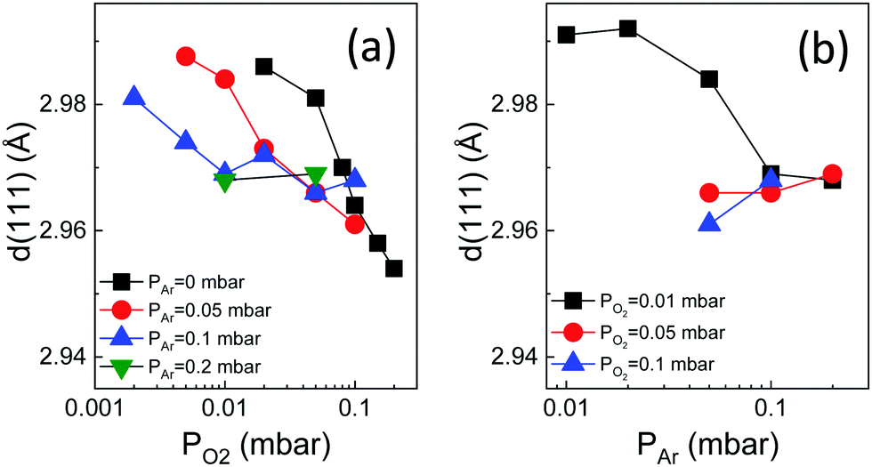 | ||
| Fig. 3 Out-of-plane lattice parameter, dHZO(111), as a function of PO2 (a) and PAr (b). In (a) PAr is 0 mbar (black squares, data reported in ref. 16), 0.05 mbar (red circles), 0.1 mbar (blue up-pointing triangles), and 0.2 mbar (green down-pointing triangles). In (b) PO2 is 0.01 mbar (black squares), 0.05 mbar (red circles), and 0.1 mbar (blue up-pointing triangles). | ||
Fig. 4a shows the dependence of the leakage current at 1 V on PO2, for fixed PAr = 0 mbar (black squares), PAr = 0.05 mbar (red circles) and PAr = 0.1 mbar (blue triangles). The corresponding leakage–voltage curves can be seen in Fig. S8 (ESI†). The leakage of the films deposited without Ar gas (PAr = 0 mbar) increases with PO2, from around 2 × 10⁻⁷ A cm−2 (PO2 = 0.01 mbar) to 3 × 10⁻⁴ A cm−2 (PO2 = 0.2 mbar).16 The films deposited under a mixed O2/Ar atmosphere and a very low PO2 in the 2 × 10⁻³–0.01 mbar range are very insulating too, with a leakage current of about 2 × 10⁻⁷ A cm−2. In contrast, the film grown under a high total pressure (PAr = 0.1 mbar and PO2 = 0.1 mbar) is much more conducting. The effect of the total pressure is evident in Fig. 4b, which shows the leakage current at 1 V as a function of PAr for fixed PO2 = 0.01 mbar (black squares), PO2 = 0.05 mbar (red circles) and PO2 = 0.1 mbar (blue triangles). The leakage current of the three PAr = 0.05 mbar samples is about 3 × 10⁻⁷ A cm−2, without a significant effect of PO2. However, in the case of the samples grown under a higher PAr, the leakage is very high when the total pressure (PAr + PO2) is about 0.2 mbar. Overall, Fig. 4 indicates that a PLD plasma thermalized by a high ambient pressure causes a strong increase in the film conductivity, whereas oxygen vacancies are not the main cause of leakage.
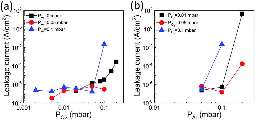 | ||
| Fig. 4 (a) Leakage current at 1 V as a function of PO2 for PAr = 0 mbar (black squares, data reported in ref. 16), PAr = 0.05 mbar (red circles) and PAr = 0.1 mbar (blue triangles). (b) Leakage current at 1 V as a function of PAr for PO2 = 0.01 mbar (black squares), 0.05 mbar (red circles), and 0.1 mbar (blue up-pointing triangles). | ||
The ferroelectric polarization loops of the films grown under fixed PAr = 0.05 mbar and varying PO2 are shown in Fig. 5a. The PO2 = 0.01 mbar and 0.02 mbar films have low remanent polarization (Pr) values of 8.3 and 17.1 μC cm−2, respectively. A slightly higher PO2, 0.05 mbar, results in a high increase of polarization, with Pr = 32 μC cm−2. Further increase of PO2 does not influence significantly the polarization loops, and the Pr of the PO2 = 0.1 mbar film is slightly lower, 30 μC cm−2. The loops of the series of films grown under fixed PAr = 0.1 mbar are shown in Fig. 5b. In agreement with the presence of the XRD o-HZO(111) reflection in the PO2 = 2 × 10⁻³ and PO2 = 5 × 10⁻³ mbar films, these films exhibit hysteretic polarization loops, with Pr = 13.8 and 18.2 μC cm−2, respectively. The Pr of the films increases with increasing PO2, being 27.8 μC cm−2 in the PO2 = 0.05 mbar film. The high leakage of the PO2 = 0.1 mbar film did not allow the measurement of a loop. The dependence of Pr on PO2 is summarized in Fig. 5c for the fixed PAr = 0 mbar (black squares), PAr = 0.05 mbar (red circles), PAr = 0.1 mbar (blue up-pointing triangles) and PAr = 0.2 mbar (green down-pointing triangle). As described above, the Pr in the PAr = 0.05 mbar and PAr = 0.1 mbar films increases with PO2. The same PO2 dependence is observed in films grown using conventional PLD (PAr = 0 mbar).16Fig. 5c evidences a huge increase in Pr in the films deposited under a mixed Ar/O2 atmosphere. The highest Pr in the PAr = 0 mbar series is 20.5 μC cm−2 (PO2 = 0.1 mbar film), while it is 32 μC cm−2 and 27.8 μC cm−2 in the PAr = 0.05 mbar and PAr = 0.1 mbar series, respectively, in both cases in films grown under PO2 = 0.05 mbar. Deposition under a higher PAr, 0.2 mbar, results in Pr reduction. The second benefit of using a mixed Ar/O2 atmosphere is that the films grown under very low PO2 (5 × 10⁻³ mbar in the PAr = 0.1 mbar series) show high ferroelectric polarization and, as shown in Fig. 4, low leakage, while PO2 above 0.02 mbar is needed in conventional PLD. The color map of Pr as a function of PAr and PO2 (Fig. 5d) evidences graphically that the optimal conditions to maximize Pr are PAr = 0.05–0.1 mbar and PO2 around 0.05 mbar. It has to be noted that the measured polarization corresponds to a projection of the ferroelectric dipoles since the films are (111)-oriented. The highest measured Pr = 32 μC cm−2 corresponds to a polarization of about 55 μC cm−2, matching well the value of spontaneous polarization calculated for ferroelectric HfO2.36,37
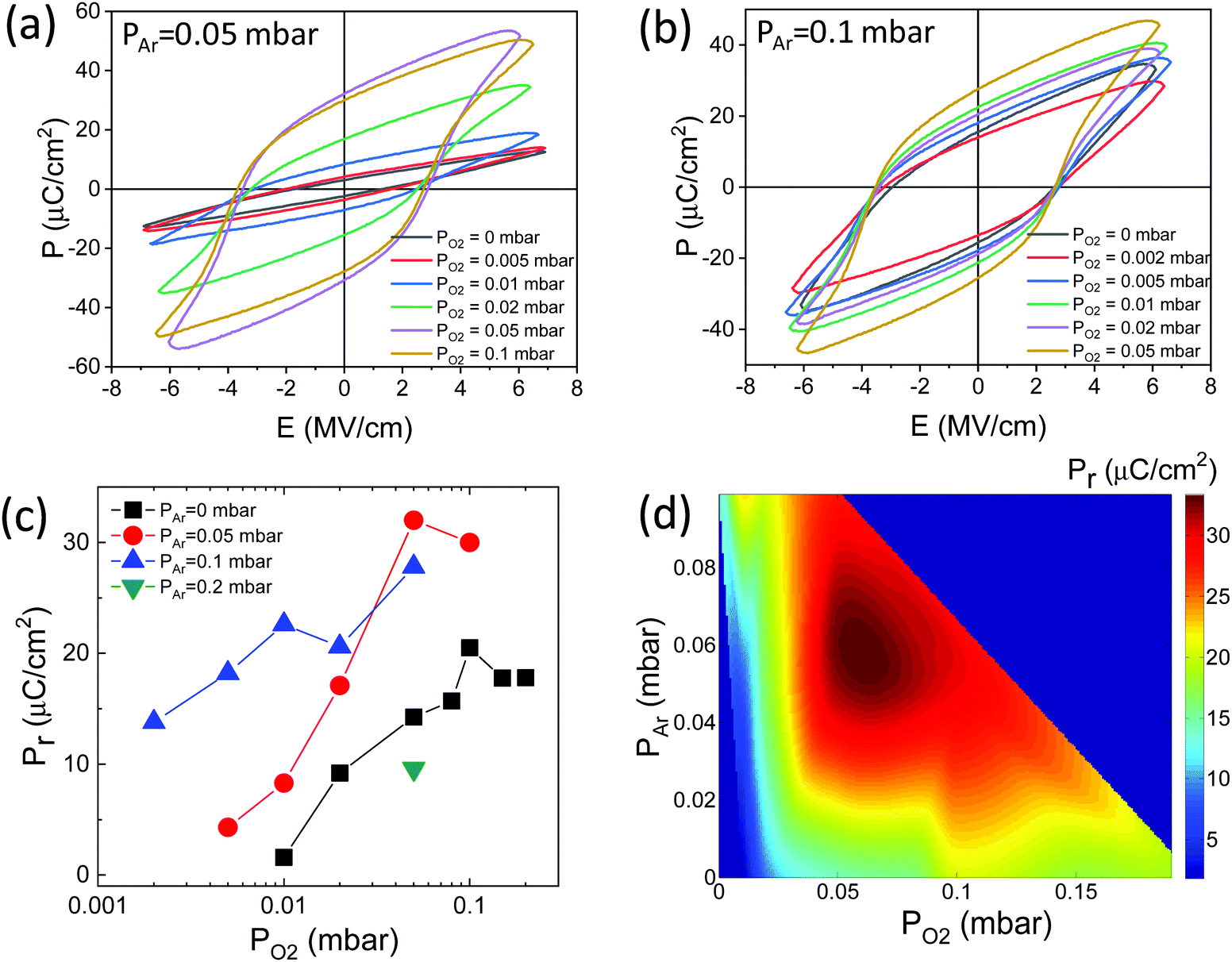 | ||
| Fig. 5 Ferroelectric polarization loops of the films grown (a) under fixed PAr = 0.05 mbar and varying PO2 and (b) under fixed PAr = 0.1 mbar and varying PO2. (c) Remanent polarization as a function of PO2, for fixed PAr = 0 mbar (black squares, data reported in ref. 16), PAr = 0.05 mbar (red circles), PAr = 0.1 mbar (blue up-pointing triangles), and 0.2 mbar (green down-pointing triangle). (d) Color map of Pr as a function of PAr and PO2. The color map has been constructed after interpolating the data of panel (c) along the PAr and PO2 axes using cubic splines. | ||
4. Conclusions
In summary, in pulsed laser deposition of ferroelectric HfO2 films, a mixed atmosphere of Ar and O2 during growth is critical. Appropriate values of Ar and O2 pressures allow independent control of plasma energy and oxidation conditions during growth. In our study, epitaxial Hf0.5Zr0.5O2(111) films deposited under a mixed Ar/O2 atmosphere show a low leakage current and have a remanent polarization of about 30 μC cm−2, which represents a 50% increase with respect to equivalent films grown by conventional pulsed laser deposition. Therefore, the simple addition of Ar gas during the growth of the film allows a large increase in ferroelectric polarization, the films probably having the intrinsic polarization of the orthorhombic phase. The new growth process will facilitate the development of epitaxial ferroelectric HfO2 and may be potentially useful in enhancing the properties of polycrystalline HfO2 and other functional oxide and nitride thin films grown by pulsed laser deposition.Conflicts of interest
There are no conflicts to declare.Acknowledgements
Financial support from the Spanish Ministry of Science and Innovation through the Severo Ochoa FUNFUTURE (CEX2019-000917-SMCIN, AEI/10.13039/501100011033), PID2020-112548RB-I00 (MCIN/AEI/10.13039/501100011033) and PID2019-107727RB-I00 (MCIN/AEI/10.13039/501100011033) projects, from CSIC through the i-LINK (LINKA20338) program, and from Generalitat de Catalunya (2017 SGR 1377) is acknowledged. The project supported by a 2020 Leonardo Grant for Researchers and Cultural Creators, BBVA Foundation is also acknowledged. IF acknowledges Ramón y Cajal contract RYC-2017-22531. TS was financially supported by China Scholarship Council (CSC) with No. 201807000104. TS's work has been done as a part of his PhD program in Materials Science at Universitat Autònoma de Barcelona.References
- T. S. Böscke, J. Müller, D. Bräuhaus, U. Schröder and U. Böttger, Appl. Phys. Lett., 2011, 99, 102903 CrossRef.
- M. H. Park, Y. H. Lee, H. J. Kim, Y. J. Kim, T. Moon, K. Do Kim, J. Müller, A. Kersch, U. Schroeder, T. Mikolajick and C. S. Hwang, Adv. Mater., 2015, 27, 1811 CrossRef CAS PubMed.
- U. Schröder, C. S. Hwang and H. Funakubo, Ferroelectricity in Doped Hafnium Oxide: Materials, Properties and Devices, Woodhead Publishing, 2019 Search PubMed.
- A. Pal, V. K. Narasimhan, S. Weeks, K. Littau, D. Pramanik and T. Chiang, Appl. Phys. Lett., 2017, 110, 022903 CrossRef.
- M. Materano, T. Mittmann, P. D. Lomenzo, C. Zhou, J. L. Jones, M. Falkowski, A. Kersch, T. Mikolajick and U. Schroeder, ACS Appl. Electron. Mater., 2020, 2, 3618 CrossRef CAS.
- U. Schroeder, M. Materano, T. Mittmann, P. D. Lomenzo, T. Mikolajick and A. Toriumi, Jpn. J. Appl. Phys., 2019, 58, SL0801 CrossRef CAS.
- Y. H. Lee, H. J. Kim, T. Moon, K. Do Kim, S. D. Hyun, H. W. Park, Y. Bin Lee, M. H. Park and C. S. Hwang, Nanotechnology, 2017, 28, 305703 CrossRef PubMed.
- T. Mittmann, M. Materano, P. D. Lomenzo, M. H. Park, I. Stolichnov, M. Cavalieri, C. Zhou, C. C. Chung, J. L. Jones, T. Szyjka, M. Müller, A. Kersch, T. Mikolajick and U. Schroeder, Adv. Mater. Interfaces, 2019, 6, 1900042 CrossRef.
- T. Mittmann, M. Michailow, P. D. Lomenzo, J. Gärtner, M. Falkowski, A. Kersch, T. Mikolajick and U. Schroeder, Nanoscale, 2021, 13, 912 RSC.
- M. H. Park, D. H. Lee, K. Yang, J. Y. Park, G. T. Yu, H. W. Park, M. Materano, T. Mittmann, P. D. Lomenzo, T. Mikolajick, U. Schroeder and C. S. Hwang, J. Mater. Chem. C, 2020, 8, 10526 RSC.
- M. Materano, P. D. Lomenzo, A. Kersch, M. H. Park, T. Mikolajick and U. Schroeder, Inorg. Chem. Front., 2021, 8, 2650 RSC.
- Y. C. Zhou, Y. K. Zhang, Q. Yang, J. Jiang, P. Fan, M. Liao and Y. C. Zhou, Comput. Mater. Sci., 2019, 167, 143 CrossRef CAS.
- I. Fina and F. Sánchez, ACS Appl. Electron. Mater., 2021, 3, 1530 CrossRef CAS.
- J. Lyu, I. Fina, R. Solanas, J. Fontcuberta and F. Sánchez, Appl. Phys. Lett., 2018, 113, 082902 CrossRef.
- Y. Wei, P. Nukala, M. Salverda, S. Matzen, H. J. Zhao, J. Momand, A. S. Everhardt, G. Agnus, G. R. Blake, P. Lecoeur, B. J. Kooi, J. Íñiguez, B. Dkhil and B. Noheda, Nat. Mater., 2018, 17, 1095 CrossRef CAS PubMed.
- J. Lyu, I. Fina, R. Solanas, J. Fontcuberta and F. Sánchez, ACS Appl. Electron. Mater., 2019, 1, 220 CrossRef CAS.
- Z. Zhang, S. Hsu, V. A. Stoica, H. Paik, E. Parsonnet, A. Qualls, J. Wang, L. Xie, M. Kumari, S. Das, Z. Leng, M. McBriarty, R. Proksch, A. Gruverman, D. G. Schlom, L. Chen, S. Salahuddin, L. W. Martin and R. Ramesh, Adv. Mater., 2021, 33, 2006089 CrossRef CAS PubMed.
- J. Lyu, I. Fina and F. Sánchez, Appl. Phys. Lett., 2020, 117, 072901 CrossRef CAS.
- T. Suzuki, T. Shimizu, T. Mimura, H. Uchida and H. Funakubo, Jpn. J. Appl. Phys., 2018, 57, 11UF15 CrossRef.
- S. Amoruso, A. Sambri and X. Wang, J. Appl. Phys., 2006, 100, 013302 CrossRef.
- A. Ojeda-G-P, M. Döbeli and T. Lippert, Adv. Mater. Interfaces, 2018, 5, 1701062 CrossRef.
- J. Gonzalo, C. N. Afonso and J. Perrière, Appl. Phys. Lett., 1995, 67, 1325 CrossRef CAS.
- C. B. Arnold and M. J. Aziz, Appl. Phys. A: Mater. Sci. Process., 1999, 69, S23 CrossRef CAS.
- S. Wicklein, A. Sambri, S. Amoruso, X. Wang, R. Bruzzese, A. Koehl and R. Dittmann, Appl. Phys. Lett., 2012, 101, 131601 CrossRef.
- C. Xu, S. Wicklein, A. Sambri, S. Amoruso, M. Moors and R. Dittmann, J. Phys. D: Appl. Phys., 2014, 47, 034009 CrossRef CAS.
- P. R. Willmott, R. Herger, C. M. Schlepütz, D. Martoccia and B. D. Patterson, Phys. Rev. Lett., 2006, 96, 176102 CrossRef CAS PubMed.
- B. Shin and M. J. Aziz, Phys. Rev. B: Condens. Matter Mater. Phys., 2007, 76, 085431 CrossRef.
- C. S. Ma, S. K. Hau, K. H. Wong, P. W. Chan and C. L. Choy, Appl. Phys. Lett., 1996, 69, 2030 CrossRef CAS.
- T. Scharf and H. U. Krebs, Appl. Phys. A: Mater. Sci. Process., 2002, 75, 551 CrossRef CAS.
- J. Gonzalo, J. Siegel, A. Perea, D. Puerto, V. Resta, M. Galvan-Sosa and C. N. Afonso, Phys. Rev. B: Condens. Matter Mater. Phys., 2007, 76, 035435 CrossRef.
- N. B. Ibrahim, C. Edwards and S. B. Palmer, J. Magn. Magn. Mater., 2000, 220, 183 CrossRef CAS.
- S. B. Ogale, R. Nawathey-Dikshit, S. J. Dikshit and S. M. Kanetkar, J. Appl. Phys., 1992, 71, 5718 CrossRef CAS.
- J. Wang, G. Rijnders and G. Koster, Appl. Phys. Lett., 2018, 113, 223103 CrossRef.
- M. Mirjolet, F. Sánchez and J. Fontcuberta, Adv. Funct. Mater., 2019, 29, 1808432 CrossRef.
- P. Nukala, J. Antoja-Lleonart, Y. Wei, L. Yedra, B. Dkhil and B. Noheda, ACS Appl. Electron. Mater., 2019, 1, 2585 CrossRef CAS PubMed.
- T. D. Huan, V. Sharma, G. A. Rossetti and R. Ramprasad, Phys. Rev. B: Condens. Matter Mater. Phys., 2014, 90, 064111 CrossRef CAS.
- F. Delodovici, P. Barone and S. Picozzi, Phys. Rev. Mater., 2021, 5, 064405 CrossRef CAS.
Footnote |
| † Electronic supplementary information (ESI) available: Sketches of the PAr and PO2 partial pressures used to grow the films. XRD θ–2θ scans of the series of films. Simulation of Laue oscillations. Thickness and growth rate as a function of PAr. XRD pole figures. Intensity of the o-(111) reflection, normalized to that of the STO(002) peak. The normalized o-(111) reflection. Leakage–voltage curves of films. See DOI: 10.1039/d1tc05387f |
| This journal is © The Royal Society of Chemistry 2022 |