A new insight into the ZIF-67 based triboelectric nanogenerator for self-powered robot object recognition†
Sugato
Hajra
a,
Manisha
Sahu
a,
Aneeta Manjari
Padhan
b,
Jaykishon
Swain
c,
Basanta Kumar
Panigrahi
d,
Hang-Gyeom
Kim
a,
Sang-Won
Bang
a,
Sukho
Park
a,
Rojalin
Sahu
 *c and
Hoe Joon
Kim
 *a
*a
aDepartment of Robotics Engineering, Daegu Gyeongbuk Institute of Science and Technology, Daegu-42988, South Korea. E-mail: joonkim@dgist.ac.kr
bDepartment of Physics, Indian Institute of Technology, Guwahati, Assam-781039, India
cSchool of Applied Sciences, Kalinga Institute of Industrial Technology (Deemed to be University), Bhubaneswar-751024, India. E-mail: rsahufch@kiit.ac.in
dDepartment of Electrical Engineering, Siksha ‘O’ Anusandhan (Deemed to be University), Bhubaneswar-751030, India
First published on 26th October 2021
Abstract
Harvesting mechanical energy from the surroundings can be a promising power source for micro/nano-devices. The triboelectric nanogenerator (TENG) works on the principle of triboelectrification and electrostatic induction. So far, metals and polymers have mostly dominated the conventional triboelectric series, but there is a need to find novel materials to extend the triboelectric series and further improve the performance of a TENG. Herein, a zeolitic imidazole framework (ZIF-67) was synthesized using a room temperature solvent-assisted route. Extensive material analysis was performed to understand its structural and chemical properties. Further, a simple vertical contact mode S-shaped TENG device (abbreviated further as S-TENG) was fabricated using an additive manufacturing approach. ZIF-67 acted as a positive triboelectric layer while Teflon/PDMS acted as a negative triboelectric layer. The multi-unit S-TENG device was further utilized for self-powered recognition of the various gaits using a digital signal processing approach. The S-TENG device based on ZIF-67 and Teflon produced a voltage of 118 V, a current of 1.7 μA, and a power density of 15 μW cm2 at a load resistance of 50 MΩ. The gait analysis of different volunteers was recorded by employing the S-TENG device and the digital signal processing route to effectively distinguish the gait patterns for the prevention of falls and injury. The S-TENG device was utilized to charge a commercial capacitor for powering a wristwatch and further it was attached to a robotic gripper for object identification.
1. Introduction
Metal–organic frameworks (MOFs) have attracted wide attention owing to their stable crystalline and porous structures. Revolutionized by Professor Omar Yaghi and coworkers in the 1990s, a MOF is synthesized by coordinative bonding between metal cations and organic linkers, forming new bulk structures by diffusing the guest molecule inside the porous structure.1 Two fundamental principles such as “Robson node-and-spacer” and “Wells strategy of combining metal–organic units and coordination polymers” were evolved by chemists to design new MOF structures.2,3 The fabrication of MOFs can be carried out by several experimental processing routes such as hydrothermal, ultrasonic, mechanochemical, or electrochemical approaches.4–7 The room temperature solvent-assisted synthesis route offers several advantages such as eco-friendly synthesis, simplistic operation, high energy efficiency, precise control over the parameters, molecular concentration stabilization, and rapid processing. The features of transformation of the functional groups and porous morphology of MOFs extend their application broadly in medicine, catalysts, gas separators, CO2 capture, and biosensors.8,9 Zeolitic imidazole frameworks (ZIFs) are a subclass of MOFs that are comprised of a metal ion and imidazole as a linker. Their structure is comparable to that of aluminosilicate zeolites. They have been widely used for industrial applications due to their chemical stability and high porosity.10Researchers are recently interested in synthesizing ZIFs by solvent-assisted and solvent-free routes, in order to generate powdered or membrane shaped ZIFs.11 The self-assembly methods support the connection between the metal ion and the imidazole linker. The construction of ZIFs and their physicochemical properties depend on the interplay between the composition, microstructure, and topology.12,13 Also, the solvent promotes ligand–ligand interactions or occupies the open pores, directing ZIF topology formation. ZIF-67 (chemical formula: Co(Hmim)2), a member of the ZIF family, forms a sodalite topology by linking 2-methylimidazole anions and cobalt cations. It crystallizes in cubic symmetry with a lattice parameter of 16.9589 Å.14 ZIF-67 offers many exciting properties such as good chemical and mechanical stability, low density, high porosity, and a large surface area. Qian et al. synthesized ZIF-67 using a hydrothermal synthesis and explored its usage in gas absorption.15 Zhong et al. have shown the applications of ZIF-67 in CO2 capture and catalysis.16 ZIF-67 was utilized as a nanopigment in epoxy coating displaying its anticorrosion behavior and self-healing abilities as reported by Lashgari et al.17 Ahmad et al. discussed the advantages of ZIF-67 derived porous carbon for designing highly efficient supercapacitors.18 Sundriyal et al. synthesized a high-performance symmetrical supercapacitor based on ZIF-67/rGO composites which showed a very high specific capacitance of 1453 F g−1.19 Becerra also used ZIF-67 particles mixed with Au for photoreduction of carbon dioxide.20
The future electronics industry is dependent upon a clean and sustainable power source. The battery used in present low-power electronics has considerable limitations concerning its low lifetime, disposal issues, and pollution.21 In nature, there are several sources of renewable energy such as solar, wind, and mechanical vibrations, which can act as alternative power sources to batteries. Professor ZL Wang and coworkers were the first to convert low-frequency vibrations into an electrical output using a triboelectric nanogenerator (TENG).22 The TENG was reported in several operating modes by following electrostatic induction and triboelectric effects.23 Although different types of nanogenerators such as piezoelectric, pyroelectric, and electromagnetic nanogenerators are studied over the years,24–27 the TENG has evolved as a strong candidate for energy harvesting due to its simple device design, cost-effectiveness, and high electrical output performance.28 The majority of the triboelectric series is dominated by metals and polymers. Hence, investigating new materials for TENG fabrication is of high research imminence among the scientific community.29 TENGs show great potential for commercialization and have been recently applied in various fields such as water treatment, dye degradation, health care systems, human safety devices, water wave harvesting, and wind speed detection.30–33
For the first time, in the present work, ZIF-67 particles synthesized by the room temperature solvent-assisted route are used as a triboelectric layer to fabricate a multi-unit vertical contact separation mode TENG. The various properties of the ZIF-67 particles are studied in detail, and a systematic investigation of the fabricated device is carried out concerning different negative triboelectric layers and frequencies. The S-TENG device can charge commercial capacitors and power low-power electronics. The single unit S-TENG device was also connected to a robotic gripper, and the electrical output was recorded by changing various objects. The approach, grasp, and release of balls with different hardness were identified, which shed light upon the potential of the device in robotic arm-based tactile sensing. The various gaits (walking, running, sitting, jumping, and jogging) of the candidates were recorded by attaching the S-TENG device to the left and right sides of the flip-flop. The forward connection was applied to the device attached to the right leg, while the reverse connection was used for the left leg to differentiate the signals between the left and the right leg. The digital signal processing techniques such as wavelet transform (WT) and wavelet packet transform (WPT) were utilized for gait recognition, elucidating the TENG device's importance towards fall detection and self-powered applications. ZIF-67 will extend the triboelectric series as a possible candidate to design TENGs with several self-powered applications.
2. Experimental techniques
The synthesis of ZIF-67 was carried out using Co(NO3)2·6H2O and 2-methyl imidazole (2-MIM) purchased from Alfa Aesar, USA. The powder X-ray diffraction (PXRD) pattern was measured using a powder diffractometer (Malvern Panalytical, Netherland) with a Cu-Kα source. PXRD data were collected within the 2θ range of 5–35° with a step size of 0.02° and a scan speed of 3 degrees per minute. A scanning electron microscope (Hitachi S-4900, Japan) was utilized to record the surface morphology, and a Bruker EDS detector was used to record the elemental mappings.The AFM and KPFM measurements were carried out by using a NanoScope V Multimode 8 AFM system and a SCM-PIT Pt/Ir-coated probe; Bruker Corporation, USA (present at KBSI, Jeonju, South Korea). During the KPFM measurement, the energy difference between the vacuum and Fermi energy levels gave rise to the surface potential of the material, while the tip–sample arrangement acted as a capacitor. The AC and DC voltage signals were simultaneously applied to the tip. The AC signal produced an electrostatic oscillation, whereas the DC signal eliminated the electrostatic oscillations, creating a difference in potential between the sample and the tip. The employed lock-in amplifier remained unresponsive towards the direct voltage signal and assisted in capturing the potential mapping by detecting the electrostatic force.
The nano-structural morphology of ZIF-67 was examined by using a field-emission transmission electron microscope (FETEM, JEOL: JEM 2011, Tokyo) at KBSI Busan, South Korea. The powder specimen was suspended in isopropyl alcohol and treated in an ultrasonic bath, and ∼5 μL of the solution was deposited on a holey carbon film-coated copper grid (200 mesh). The chemical composition and electronic properties of ZIF-67 were analyzed using X-ray photoelectron spectroscopy (XPS) measurements performed with the Thermo Scientific Escalab 250Xi, using an Al-Kα line (1486.6 eV) as an excitation source at a base pressure of 10−7 mbar. The XPS data were recorded over a wide range of binding energies from 0 to 1100 eV.
The room temperature Raman spectroscopic measurements were carried out using a Nicolet Almega XR dispersive Raman spectrometer (Thermo Scientific, USA) with a 532 nm excitation laser source to reaffirm the structural analysis. The thermogravimetric measurements were carried out from room temperature to 1000 °C at a heating rate of 5 °C min−1 using a TGA instrument (Auto Q500, USA). An N2 adsorption–desorption isotherm system (Micrometrics ASAP 2020) was utilized to record the Brunauer–Emmett–Teller (BET) analysis of the ZIF-67 sample at 77 K. Fourier-transform infrared spectra (FT-IR) were traced using a Thermo Scientific/Nicolet Continuum spectrometer, USA, in ATR mode.
A Keithley 6514 electrometer, USA, was used to measure the electrical output of the TENG. The digital signal processing approach was undertaken to analyze the gait movements of volunteers by attaching the S-TENG device to flip-flops. MATLAB R2016a software was used to carry out all the WT and WPT decomposition of the gait patterns. The third decomposition level of the Daubechies mother wavelet was selected for the gait analysis of the volunteers.
3. Results and discussion
The systematic synthesis route for ZIF-67 is illustrated in Fig. 1a. First, 1.24 g of Co(NO3)2·6H2O and 1.50 g of 2-MIM were dissolved in 50 ml of methanol separately. Then, the Co(NO3)2·6H2O solution was added slowly to the 2-MIM solution while stirring vigorously. The mixture was stirred at room temperature for 6 h. As the two solutions were combined, a purple precipitate was formed. Then the particles were separated by centrifugation. They were washed two times with methanol and subsequently dried in an oven at 60°. The layer-by-layer arrangement of the fabrication of the TENG device is illustrated in Fig. 1b. At first, an S-shaped structure was 3D printed using a fused filament fabrication (FFF) 3D printing technology. A 3D printer (M/S Ultimaker, Netherland) comprising of a dual nozzle was employed to print the S-shaped structure formed by foaming thermoplastic polyurethane (TPU) material. Secondly, the double sided conductive copper tape electrode (M/S 3M tapes, USA) was attached on all opposite sides and the copper wire was connected to it. Finally, the ZIF-67 particles were pressed over the copper tape acting as a postive triboelectric layer. The opposite negative triboelectric layers were attached to opposite side copper electrode completing the design of the S-shaped TENG having multiple units configuration.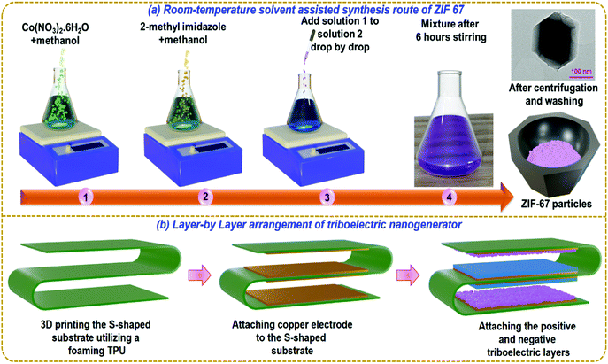 | ||
| Fig. 1 (a) Synthesis of ZIF-67 particles and (b) layer-by-layer arrangement for fabrication of the S-TENG device. | ||
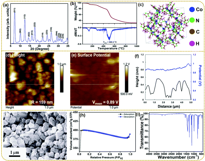
The material characterization sheds light upon the various physicochemical properties of the synthesized material. Fig. 2a shows the XRD patterns of the as-synthesized ZIF-67. All the diffraction peaks are identical to the corresponding simulated pattern (Fig. S1, ESI†). The corresponding Bragg reflections of (0 1 1), (0 0 2), (1 1 2), (0 2 2), (0 1 3), (2 2 2), (1 1 4), (2 3 3), (1 3 4), (0 4 4), (3 3 4), (2 4 4), (2 3 5) in the 2θ range of 5°–35° confirm the successful synthesis of ZIF-67 and are in good agreement with the earlier reported data.34 The presence of sharp diffraction peaks in the PXRD pattern is ascribed to the high crystallinity of synthesized ZIF-67. No other peaks corresponding to any impurity phases are observed within the resolution limit of the powder X-ray diffractometer suggesting the qualitative synthesis of ZIF-67. Fig. 2b presents the TGA and the derivative curves for the as-prepared ZIF-67. The TGA analysis, carried out under an air atmosphere, depicts multiple steps of weight loss in the temperature range of 25 °C to 1000 °C. The as-prepared ZIF-67 first released physically adsorbed water and residual solvents, resulting in the foremost weight loss within the range of 50–270 °C. Also, a considerable weight loss occurs from 271 to 458 °C owing to the plausible decomposition and volatilization of the remaining bound water molecules. A significant weight loss (∼34.87%) further occurs in the temperature range of 460–540 °C, ascribed to the thermal decomposition of ZIF-67, indicating the collapse of the framework structure. The degradation temperature (TDEG), estimated from the peak of the derivative curve within the aforementioned temperature range, is obtained to be 505 °C (shown in the derivative curve). The last mass loss was observed in the range of 600–1000 °C, which is related to the collapse of the crystal structure through the previous step.35 The molecular structure of ZIF-67 has been modeled using the crystallographic information using the commercial software “VESTA” in Fig. 2c.
Fig. 2d shows the surface topography of the ZIF-67 particles and the estimated surface roughness over a 5 μm by 5 μm area is 159 nm. Fig. 2e shows the surface potential profile measured using KPFM. As the surface atoms play an essential role in determining triboelectric properties, KPFM analysis is crucial for studying the surface potential of a triboelectric layer. The synthesized ZIF-67 particles show a positive surface potential of 0.89 V and can act as a positive triboelectric layer. The line profile of the surface potential and surface roughness are also depicted in Fig. 2f. The surface morphology of the synthesized ZIF-67 particles was studied by using a scanning electron microscope (SEM). The SEM image of the synthesized ZIF demonstrates a smooth, randomly oriented, and nano-crystalline polyhedral or rhombic dodecahedral morphology.36 The particle size of the synthesized ZIF-67 varies from 400 to 500 nm with a small agglomeration. Fig. S2 (ESI†) shows the SEM image of the copper electrode and copper electrode with ZIF-67 particles. The image shows that ZIF-67 particles are firmly attached to the copper electrode and maintain their original morphology. Further, the gas absorption plot obtained using BET surface area measurements for the ZIF-67 sample is shown in Fig. 2h. ZIF-67 shows an ultra-high surface area of 1263.08 m2 g−1 and a pore diameter of 23.44 nm.
Fig. 2i shows the FT-IR spectra of the synthesized ZIF-67 recorded in the range of 4000–400 cm−1. The characteristic bands at 3128 and 2927 cm−1 confirm the presence of the aromatic and aliphatic C–H stretching modes of 2-methylimidazole, respectively. The bands in the region of 1502–600 cm−1 are ascribed to the bending and stretching modes of the imidazole ring in ZIF-67, while the stretching modes of C![[double bond, length as m-dash]](https://www.rsc.org/images/entities/char_e001.gif) C stretching vibrations are observed at 1578 cm−1. Also, the major peaks at 1420, 1306, and 1176 cm−1 are assigned to the C
C stretching vibrations are observed at 1578 cm−1. Also, the major peaks at 1420, 1306, and 1176 cm−1 are assigned to the C![[double bond, length as m-dash]](https://www.rsc.org/images/entities/char_e001.gif) N stretching, C–N stretching and C–H bending vibrations, all related to vibrations of the imidazole ring, respectively. The peaks in the range of 755–465 cm−1 are attributed to the Co–N coordination bonds. All these vibrational modes confirm the formation of the Co–imidazole complex in the synthesized ZIF-67.37–39
N stretching, C–N stretching and C–H bending vibrations, all related to vibrations of the imidazole ring, respectively. The peaks in the range of 755–465 cm−1 are attributed to the Co–N coordination bonds. All these vibrational modes confirm the formation of the Co–imidazole complex in the synthesized ZIF-67.37–39
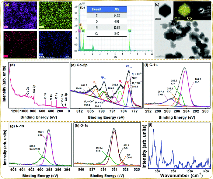
Fig. 3a shows the elemental mappings revealing a homogeneous distribution of Co, C, N, and O, indicating the proper synthesis of ZIF-67. The compositional analysis by EDS elucidates the spectral lines of Co along with those of C, N, and O, confirming the phase purity of ZIF-67 as shown in Fig. 3b. The at% compositions of the respective elements are provided in the inset. Fig. 3c presents the BF-TEM images of ZIF-67 nanoparticles along with a single crystal, elemental mapping for Co, and the SAED pattern of ZIF-67. BF-TEM images display fairly uniform rhombic dodecahedral-shaped crystals with an average size of 350–500 nm.40 The EDS elemental mapping confirms the homogeneous distribution of Co metal ions throughout the crystal. Also, the SAED pattern displays the concentric diffraction rings corresponding to the ZIF-67 structure, which shows a good agreement with the PXRD results.
To further ensure the chemical composition and states of the elements present in ZIF-67, XPS measurements were carried out using an Al-Kα (1486.6 eV) line as the X-ray source. All the binding energies of the analysis were calibrated using the C-1s peak at 284.5 eV. Fig. 3d–h presents the XPS survey spectra, which reveal Co, C, N, and O as the elemental compositions. The Co-2p XPS spectra in Fig. 3e show two major peaks of Co-2p3/2 and Co-2p1/2 levels, along with the weak intensity satellite peaks located at 785.9 eV (S1) and 801.8 eV (S2). The Co-2p3/2 level splits into a doublet at D1 = 780.3 eV and D2 = 782.1 eV, whereas the Co-2p1/2 level deconvolutes into two peaks centered at D3 = 796.1 eV and D4 = 796.9 eV. The Co-2p core level of Co2+ and Co3+ is well known to exhibit similar binding energy peaks near 780 eV and 796 eV characteristic of Co-2p3/2 and Co-2p1/2 levels, respectively. However, the energy splitting (ΔE) between the levels should differ for both cations due to the spin–orbit coupling with a ΔE = 15.8 eV for Co2+ and ΔE = 15 eV for Co3+. For ZIF-67, the energy gap between the doublet peaks is obtained to be 15.8 eV and 14.8 eV. These results confirm the presence of both Co2+ and Co3+ cationic states in the prepared material.39,41–43 The C-1s spectrum in Fig. 3f deconvolutes into four distinguished peaks centered at 284.1, 285.3, 286.1, and 287.3 eV corresponding to C–C, C–N, C–O, and C![[double bond, length as m-dash]](https://www.rsc.org/images/entities/char_e001.gif) O groups, respectively.44 Further, the XPS spectra for O-1s are shown in Fig. 3g. The deconvoluted O-1s peak positions are assigned to Co–O (529 eV), C–O (531.1 eV), and C
O groups, respectively.44 Further, the XPS spectra for O-1s are shown in Fig. 3g. The deconvoluted O-1s peak positions are assigned to Co–O (529 eV), C–O (531.1 eV), and C![[double bond, length as m-dash]](https://www.rsc.org/images/entities/char_e001.gif) O (532.6 eV).45 Similarly, the XPS spectrum of N-1s splits into two distinct peaks in Fig. 3h. The peak at 398.1 eV corresponds to the C–N bond, whereas the spectral line at 399.3 eV is ascribed to the Co–N/N–O groups.46,47
O (532.6 eV).45 Similarly, the XPS spectrum of N-1s splits into two distinct peaks in Fig. 3h. The peak at 398.1 eV corresponds to the C–N bond, whereas the spectral line at 399.3 eV is ascribed to the Co–N/N–O groups.46,47
To further understand the vibrational properties and confirm the structure of ZIF-67, Raman spectral results collected in the 100–2000 cm−1 region are shown in Fig. 3i. The as-synthesized ZIF-67 shows prominent vibrational modes at 182, 263, 429, 682, 1144, 1178, 1381, and 1455 cm−1, matching the reported literature.36 The XRD pattern in Fig. 2a confirms the twelve-sided structure with high symmetry, which is consistent with Raman spectra in the reported literature.48 The above characterization confirms the successful synthesis of the ZIF-67 sample and also provides details regarding its use as a potential triboelectric material. To confirm this, a TENG device was fabricated, and the device performance using the ZIF-67 material was studied in detail.
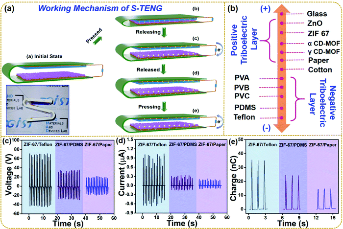
The working mechanism of the fabricated S-TENG device operated in a vertical contact separation mode is shown in Fig. 4a. The inset of the figure shows the digital image of the multi-unit S-TENG device. The triboelectrification and electrostatic induction phenomena contribute towards the output of the device. In Fig. 4a, panel (a) illustrates the initial state of the device, where no charge is generated due to the absence of any applied force; and panel (b) shows the positive and negative triboelectric layers fully in contact with each other. Hence, equal and opposite charges are generated on the triboelectric layers. ZIF-67 is positive as compared to Teflon, so the negative charge is generated upon the Teflon layer. When the force is released, the device moves to regain its initial state, leading to a potential difference between the two electrodes. Hence, electrons move from the top electrode to the bottom electrode due to the potential difference as shown in panel (c). The flow of electrons continues until the two triboelectric layers are fully separated as in panel (d). The first half-cycle of the electrical output comes from this flow of electrons. As the S-TENG is subjected to a force, the upper and bottom triboelectric layers come close to each other, leading to the flow of electrons in the reverse direction (e). The movement of electrons is from the bottom electrode to the upper electrode, forming the other half-cycle of the electrical output. Thus, the output of the S-TENG device can be achieved by periodic contact and separation.
Fig. 4b demonstrates the triboelectric series showing the various triboelectric materials for the extension of the conventional triboelectric series.49Fig. 4c shows the voltage output of the multiunit TENG comprising of ZIF-67 as a positive triboelectric layer and as the opposite layer Teflon (negative triboelectric layer), PDMS (negative triboelectric layer), and paper (positive triboelectric layer). It is seen that the output follows the trend of the triboelectric series. ZIF-67/Teflon gives a voltage output of 117 V while ZIF-67/PDMS gives a voltage output of 60 V. However, the output voltage of ZIF-67/paper decreases to 30 V as both the layers have the same positive surface potential. The current and charge generated by the same devices are shown in Fig. 4d and e, respectively. The current and charge of the multiunit S-TENG devices showed the following trend: ZIF-67/Teflon: 1.7 μA; 35 nC > ZIF-67/PDMS: 0.3 μA; 24 nC > ZIF-67/Paper: 0.17 μA; 13 nC, respectively.
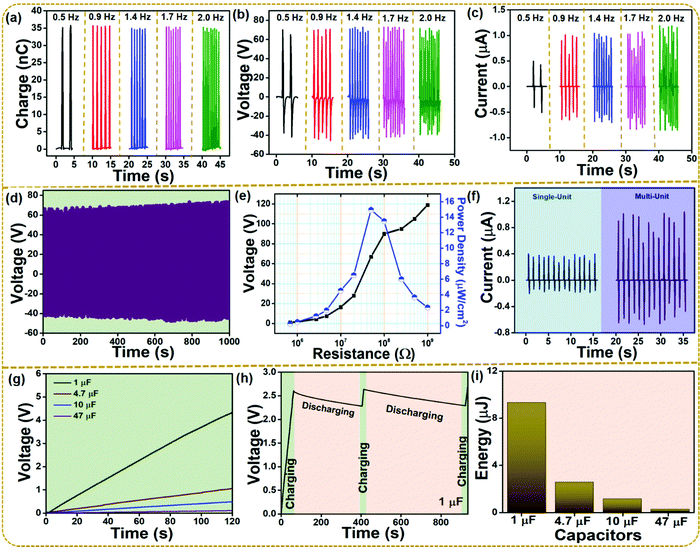
The ZIF-67/Teflon-based S-TENG device was further considered for evaluating the electrical performance for various frequencies. Fig. 5a–c show the charge, voltage, and current output of the ZIF-67/Teflon-based S-TENG device under various external frequencies from 0.5 Hz to 2 Hz. The voltage of 117 V was not affected by the change in the external frequencies, whereas the current value significantly increased. This increase in the current value is attributed to the increased rate of charge flow across the external load. Meanwhile, the voltage was the same as the total charge transferred was constant, as shown in Fig. 5a and b. As robustness and stability of the S-TENG need to be evaluated under a long period of mechanical deformation, the device was operated for 1000 seconds at 0.9 Hz. The voltage was observed to be invariant throughout the operation as shown in Fig. 5d. Fig. 5e shows the corresponding voltage and power density of the S-TENG device at different load resistance in the kΩ to MΩ range. The mathematical equation PD = V2/RA (A is the active area of the electrodes) is used to calculate the power density of the S-TENG device. The highest power density value was 15 μW cm−2 at a load resistance of 50 MΩ. Fig. 5f shows the current output of the single unit and multi-unit S-TENG device. As the two units were connected in parallel, the voltage remained constant while the current increased. The single and multi-unit S-TENG devices produced a current of 0.56 μA and 1.7 μA, respectively. Various capacitors (1, 4.7, 10, and 47 μF) were charged for over 120 s using a bridge rectifier circuit, as shown in Fig. 5g. The AC output of the S-TENG device was converted to a DC signal using the bridge rectifier circuit. Fig. 5h shows the charging and discharging profiles of a 1 μF capacitor using the ZIF-67/Teflon-based S-TENG device suggesting a stable output generation from the S-TENG device over a long period where instantaneous charging is possible after a discharge. Fig. 5i shows the energy stored in the commercial capacitors as they are charged up to 120 s. It was evaluated by using a mathematical expression: E = ½ CV2.50
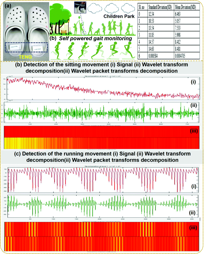
Playing and exercising for children is very important to maintain a good lifestyle. But small children need supervision to avoid small injuries or falls. We propose that the fabricated S-TENG device should be attached to the flip-flop for tracking various gait patterns to address this problem. Fig. 6a shows the attachment of the S-TENG device on the flip-flop and the table shows the standard deviation and mean deviation of various types of gaits as predicted from the wavelet transform single processing technique. The supervisor will be able to monitor the gaits to avoid any physical injury in the playground. Seven different gait patterns of volunteers were employed in this study: slow walk, jumping, quick walking, slow jogging, slow running, fast running, and sitting. The different gait patterns are considered for checking the robustness of the proposed techniques. It is observed that WT and WPT detect the gait patterns of the volunteers quite effectively and correctly. Various gaits of the volunteers are distinguishable from the contours, the color code in WPT, thereby detecting the activity. It is also observed that the color combination during sitting is different from that during running. The detections of sitting and running movements of the volunteers using WPT are shown in Fig. 6b(iii) and c(iii), respectively. The signal recorded from the nanogenerator during sitting and running is shown in Fig. 6b and c(i). In this proposed section, seven different gaits of individuals are used as the input obtained from the electrical output of the S-TENG device and further fed into the WT. Then the standard deviation (SD) and mean deviation (MD) are calculated for different walking patterns and are presented in the table in Fig. 6a. It is observed from the comparison that the SD and MD values vary from sitting to running or from jumping to running movements. Then based on the observations of these values, the threshold values are fixed. If the SD and MD are higher than the selected threshold values, then the volunteers are considered to be moving. Further to support the analysis, the wavelet transform decomposition signal is shown in Fig. 6b and c(ii). Fig S3 (ESI†) shows the WT of the various gait signals obtained from the S-TENG device attached to seven different individuals. The suggested tracking of the gait patterns will help the instructors to instruct the individuals based on the SD and MD values to warn the individuals to avoid any fall or injury by abnormal gait activity. The WT and WPT techniques could effectively characterize and identify both time and frequency localization based on the variation of contours and statistical parameters such as standard deviation.
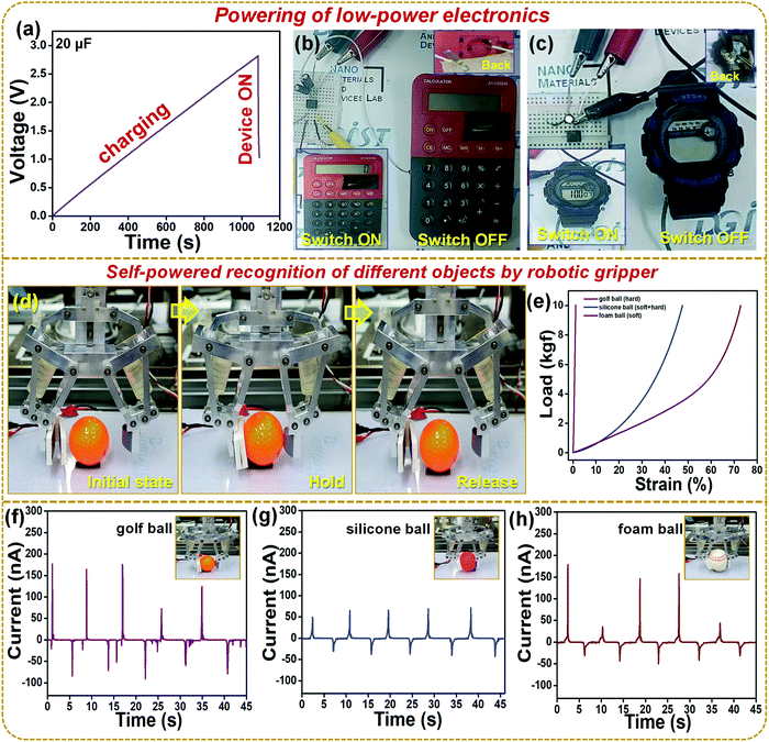
Fig. 7a shows the charging of a 20 μF capacitor using the S-TENG device and rectification circuit. Fig. 7b shows the digital image of the switch ON and switch OFF condition of a calculator whereas Video S1 (ESI†) shows the powering of the calculator. Fig. 7c shows the digital image of the switch ON and switch OFF condition of a wristwatch and Video 2 (ESI†) shows the powering of a wristwatch. Hence Fig. 7b and c show that the S-TENG device can act as a sustainable power source for various low power electronics and in the future become an alternative to battery units. Fig. 7d shows the digital picture of the robotic gripper where the single unit of the S-TENG device was connected to the grasping arm. Three stages are shown as the initial state, hold, and release conditions of a golf ball using the robotic gripper. The hold and release were performed five times and the corresponding current outputs were recorded. Fig. 7e shows that for an equal amount of load the strain % is different for various balls employed during the robotic gripper experiment, where the golf ball (hard), silicon ball (hard + soft), and foam ball (soft) were employed. Fig. 7f–h show the current outputs of the S-TENG device while holding and releasing different types of balls. The output from the S-TENG device can be correlated with the mechanical properties of the ball, as the current output increases with the object's hardness. The hardball does not deform much as the soft or (hard + soft) ball which is directly correlated to the mechanical properties in Fig. 7e. Hence inspite of an equal amount of force of holding the three different balls by the robotic gripper, the hardball could be able to generate more charges on the S-TENG surface leading to higher output. These results elucidate that the TENG device can be used in various robotic systems to design self-powered touch, pressure, or tactile sensors for object identification shortly.
4. Conclusion
This work presents a cost-effective room temperature solvent-assisted synthesis of ZIF-67 particles and their application in TENGs. The XRD analysis suggested the formation of highly phase pure crystalline particles and the surface micrographs depicted uniform polyhedral or rhombic dodecahedral morphology. The synthesized ZIF-67 particles showed a positive surface potential of 0.89 V and an ultra-high surface area of 1263.08 m2 g−1. The S-TENG device based on ZIF-67 and Teflon produced a voltage of 118 V, a current of 1.7 μA, and a power density of 15 μW cm−2 at a load resistance of 50 MΩ. Further, the digital signal processing techniques were utilized in the present work to understand the various gait movements of the volunteers during daily activities. This type of self-powered gait analysis using the TENG device can monitor abnormal gaits and avoid individuals from injuries. Further, the S-TENG device was attached to a robotic gripper and the balls with different hardness were held and released, resulting in different current outputs of the S-TENG device, which elucidated its potential usage in robotics engineering. Lastly, the S-TENG device was used as a sustainable power source for low-power electronics.Author contributions
Sugato Hajra: conceptualization, formal analysis, investigation, writing – original draft; Manisha Sahu: data curation, software; Aneeta Manjari Padhan: formal analysis, writing – review and editing; Jaykishon Swain: data curation; Basanta Kumar Panigrahi: software; Hang-Gyeom Kim: data curation; Sang-Won Bang: data curation; Sukho Park: resources, writing – review and editing; Rojalin Sahu: supervision, writing – review; Hoe Joon Kim: funding acquisition, writing – review and editing, supervision.Conflicts of interest
There are no conflicts to declare.Acknowledgements
This study was supported by the Basic Science Research Program through the National Research Foundation of Korea (NRF), funded by the Ministry of Science and ICT of Korea (2021R1C1C1011588) and the DGIST R&D Program of the Ministry of Science and ICT of Korea (21-RT-01). S. H. and H. J. K. like to thank Professor Sangaraju Shanmugam, DGIST, for providing the BET analysis facility.References
- H. Li, M. Eddaoudi, M. O'Keeffe and O. M. Yaghi, Design and synthesis of an exceptionally stable and highly porous metal-organic framework, Nature, 1999, 402(6759), 276–279 CrossRef CAS.
- B. Moulton and M. J. Zaworotko, From Molecules to Crystal Engineering:
![[thin space (1/6-em)]](https://www.rsc.org/images/entities/char_2009.gif) Supramolecular Isomerism and Polymorphism in Network Solids, Chem. Rev., 2001, 101(6), 1629–1658 CrossRef CAS PubMed.
Supramolecular Isomerism and Polymorphism in Network Solids, Chem. Rev., 2001, 101(6), 1629–1658 CrossRef CAS PubMed. - C. Wang, R. Vernon, O. Lange, M. Tyka and D. Baker, Prediction of structures of zinc-binding proteins through explicit modeling of metal coordination geometry, Protein Sci., 2010, 19(3), 494–506 CrossRef CAS.
- S. Hajra, M. Sahu, A. M. Padhan, I. S. Lee, D. K. Yi, P. Alagarsamy, S. S. Nanda, H. J. Kim and A. Green, Metal–Organic Framework-Cyclodextrin MOF: A Novel Multifunctional Material Based Triboelectric Nanogenerator for Highly Efficient Mechanical Energy Harvesting, Adv. Funct. Mater., 2021, 2101829 CrossRef CAS.
- M. Samal, J. Panda, B. P. Biswal and R. Sahu, Kitchen grinder: a tool for the synthesis of metal–organic frameworks towards size selective dye adsorption, CrystEngComm, 2018, 20(18), 2486–2490 RSC.
- J. Park, Z. U. Wang, L.-B. Sun, Y.-P. Chen and H.-C. Zhou, Introduction of functionalized mesopores to metal–organic frameworks via metal–ligand–fragment coassembly, J. Am. Chem. Soc., 2012, 134(49), 20110–20116 CrossRef CAS.
- R. Banerjee, A. Phan, B. Wang, C. Knobler, H. Furukawa, M. O'Keeffe and O. M. Yaghi, High-throughput synthesis of zeolitic imidazolate frameworks and application to CO2 capture, Science, 2008, 319(5865), 939–943 CrossRef CAS.
- F. Martínez, R. Sanz, G. Orcajo, D. Briones and V. Yángüez, Amino-impregnated MOF materials for CO2 capture at post-combustion conditions, Chem. Eng. Sci., 2016, 142, 55–61 CrossRef.
- X. Wei, L. Zheng, F. Luo, Z. Lin, L. Guo, B. Qiu and G. Chen, Fluorescence biosensor for the H 5 N 1 antibody based on a metal–organic framework platform, J. Mater. Chem. B, 2013, 1(13), 1812–1817 RSC.
- S. Payra, K. L. Reddy, R. S. Sharma, S. Singh and S. Roy, A trade-off between adsorption and photocatalysis over ZIF-derived composite, J. Hazard. Mater., 2020, 393, 122491 CrossRef CAS.
- Y.-R. Lee, M.-S. Jang, H.-Y. Cho, H.-J. Kwon, S. Kim and W.-S. Ahn, ZIF-8: A comparison of synthesis methods, Chem. Eng. J., 2015, 271, 276–280 CrossRef CAS.
- C.-W. Tsai and E. H. Langner, The effect of synthesis temperature on the particle size of nano-ZIF-8, Microporous Mesoporous Mater., 2016, 221, 8–13 CrossRef CAS.
- W. Liang, R. Ricco, N. K. Maddigan, R. P. Dickinson, H. Xu, Q. Li, C. J. Sumby, S. G. Bell, P. Falcaro and C. J. Doonan, Control of structure topology and spatial distribution of biomacromolecules in protein@ ZIF-8 biocomposites, Chem. Mater., 2018, 30(3), 1069–1077 CrossRef CAS.
- C. Duan, Y. Yu and H. Hu, Recent progress on synthesis of ZIF-67-based materials and their application to heterogeneous catalysis, Green Energy Environ., 2020, https://www.sciencedirect.com/science/article/pii/S2468025720302582 Search PubMed.
- J. Qian, F. Sun and L. Qin, Hydrothermal synthesis of zeolitic imidazolate framework-67 (ZIF-67) nanocrystals, Mater. Lett., 2012, 82, 220–223 CrossRef CAS.
- G. Zhong, D. Liu and J. Zhang, The application of ZIF-67 and its derivatives: adsorption, separation, electrochemistry and catalysts, J. Mater. Chem. A, 2018, 6(5), 1887–1899 RSC.
- S. M. Lashgari, H. Yari, M. Mahdavian, B. Ramezanzadeh, G. Bahlakeh and M. Ramezanzadeh, Application of nanoporous cobalt-based ZIF-67 metal-organic framework (MOF) for construction of an epoxy-composite coating with superior anti-corrosion properties, Corros. Sci., 2021, 178, 109099 CrossRef CAS.
- R. Ahmad, U. A. Khan, N. Iqbal and T. Noor, Zeolitic imidazolate framework (ZIF)-derived porous carbon materials for supercapacitors: an overview, RSC Adv., 2020, 10(71), 43733–43750 RSC.
- S. Sundriyal, V. Shrivastav, H. Kaur, S. Mishra and A. Deep, High-Performance Symmetrical Supercapacitor with a Combination of a ZIF-67/rGO Composite Electrode and a Redox Additive Electrolyte, ACS Omega, 2018, 3(12), 17348–17358 CrossRef CAS.
- J. Becerra, D.-T. Nguyen, V.-N. Gopalakrishnan and T.-O. Do, Plasmonic Au Nanoparticles Incorporated in the Zeolitic Imidazolate Framework (ZIF-67) for the Efficient Sunlight-Driven Photoreduction of CO2, ACS Appl. Energy Mater., 2020, 3(8), 7659–7665 CrossRef CAS.
- H. D. Pham, M. Horn, J. F. Fernando, R. Patil, M. Phadatare, D. Golberg, H. Olin and D. P. Dubal, Spent graphite from end-of-life Li-ion batteries as a potential electrode for aluminium ion battery, Sustainable Mater. Technol., 2020, 26, e00230 CrossRef CAS.
- Y. Wang, Y. Yang and Z. L. Wang, Triboelectric nanogenerators as flexible power sources, npj Flexible Electron., 2017, 1(1), 10 CrossRef.
- M. Sahu, S. Hajra, J. Bijelic, D. Oh, I. Djerdj and H. J. Kim, Triple perovskite-based triboelectric nanogenerator: a facile method of energy harvesting and self-powered information generator, Mater. Today Energy, 2021, 20, 100639 CrossRef CAS.
- P. K. Annamalai, A. K. Nanjundan, D. P. Dubal and J.-B. Baek, An Overview of Cellulose-Based Nanogenerators, Adv. Mater. Technol., 2021, 6(3), 2001164 CrossRef CAS.
- A.-S. Siao, C.-C. Hsiao and C.-K. Chao, Investigation and Evaluation of Pyroelectric Materials for Thermal Energy Harvesting, Phys. Status Solidi A, 2020, 217(1), 1900716 CrossRef CAS.
- X. Ren, H. Fan, C. Wang, J. Ma, S. Lei, Y. Zhao, H. Li and N. Zhao, Magnetic force driven noncontact electromagnetic-triboelectric hybrid nanogenerator for scavenging biomechanical energy, Nano Energy, 2017, 35, 233–241 CrossRef CAS.
- S. Hajra, M. Sahu, D. Oh and H. J. Kim, Lead-free and flexible piezoelectric nanogenerator based on CaBi4Ti4O15 Aurivillius oxides/PDMS composites for efficient biomechanical energy harvesting, Ceram. Int., 2021, 47(11), 15695–15702 CrossRef CAS.
- J. Chen and Z. L. Wang, Reviving Vibration Energy Harvesting and Self-Powered Sensing by a Triboelectric Nanogenerator, Joule, 2017, 1(3), 480–521 CrossRef CAS.
- S. K. Karan, S. Maiti, J. H. Lee, Y. K. Mishra, B. B. Khatua and J. K. Kim, Recent Advances in Self-Powered Tribo-/Piezoelectric Energy Harvesters: All-In-One Package for Future Smart Technologies, Adv. Funct. Mater., 2020, 30(48), 2004446 CrossRef CAS.
- Z. Liu, Q. Zheng, Y. Shi, L. Xu, Y. Zou, D. Jiang, B. Shi, X. Qu, H. Li, H. Ouyang, R. Liu, Y. Wu, Y. Fan and Z. Li, Flexible and stretchable dual mode nanogenerator for rehabilitation monitoring and information interaction, J. Mater. Chem. B, 2020, 8(16), 3647–3654 RSC.
- Z. L. Wang, Triboelectric Nanogenerators as New Energy Technology for Self-Powered Systems and as Active Mechanical and Chemical Sensors, ACS Nano, 2013, 7(11), 9533–9557 CrossRef CAS PubMed.
- Y. Mao, Y. Li, J. Xie, H. Liu, C. Guo and W. Hu, Triboelectric nanogenerator/supercapacitor in-one self-powered textile based on PTFE yarn wrapped PDMS/MnO2NW hybrid elastomer, Nano Energy, 2021, 84, 105918 CrossRef CAS.
- Y. Y. Ke, T. M. Chou and Z. H. Lin, Development of Functional Triboelectric Nanogenerators for Antibacterial Applications, ECS Trans., 2016, 72(6), 53–57 CrossRef CAS.
- J. Zhang, Y. Cai and K. Liu, Extremely effective boron removal from water by stable metal organic framework ZIF-67, Ind. Eng. Chem. Res., 2019, 58(10), 4199–4207 CrossRef CAS.
- Y. Luo, W. Cui, Y. Zou, H. Chu, F. Xu and L. Sun, Thermal decompositions and heat capacities study of a co-based zeolitic imidazolate framework, J. Therm. Anal. Calorim., 2020, 142(2), 891–898 CrossRef CAS.
- H. Pan, X. Wang, H. Chu, Y. Li, S. Zhao, G. Li and D. Li, Optical modulation characteristics of zeolitic imidazolate framework-67 (ZIF-67) in the near infrared regime, Opt. Lett., 2019, 44(24), 5892–5895 CrossRef CAS PubMed.
- J. Chang, Y. Wang, L. Chen, D. Wu, F. Xu, Z. Bai, K. Jiang and Z. Gao, Cobalt nanoparticles embedded nitrogen doped carbon, preparation from alkali deprotonation assisted ZIF-67 and its electrocatalytic performance in oxygen evolution reaction, Int. J. Hydrogen Energy, 2020, 45(23), 12787–12797 CrossRef CAS.
- K. Archana, N. G. Pillai, K. Y. Rhee and A. Asif, Super paramagnetic ZIF-67 metal organic framework nanocomposite, Composites, Part B, 2019, 158, 384–389 CrossRef CAS.
- J. Qin, S. Wang and X. Wang, Visible-light reduction CO2 with dodecahedral zeolitic imidazolate framework ZIF-67 as an efficient co-catalyst, Appl. Catal., B, 2017, 209, 476–482 CrossRef CAS.
- S. A. Ahmed, D. Bagchi, H. A. Katouah, M. N. Hasan, H. M. Altass and S. K. Pal, Enhanced water stability and photoresponsivity in metal-organic framework (MOF): a potential tool to combat drug-resistant bacteria, Sci. Rep., 2019, 9(1), 1–11 CAS.
- J. Cao, C. Lei, J. Yang, X. Cheng, Z. Li, B. Yang, X. Zhang, L. Lei, Y. Hou and K. Ostrikov, An ultrathin cobalt-based zeolitic imidazolate framework nanosheet array with a strong synergistic effect towards the efficient oxygen evolution reaction, J. Mater. Chem. A, 2018, 6(39), 18877–18883 RSC.
- S. Nayak, S. Thota, D. C. Joshi, M. Krautz, A. Waske, A. Behler, J. Eckert, T. Sarkar, M. S. Andersson, R. Mathieu, V. Narang and M. S. Seehra, Magnetic compensation, field-dependent magnetization reversal, and complex magnetic ordering in Co2TiO4, Phys. Rev. B: Condens. Matter Mater. Phys., 2015, 92(21), 214434 CrossRef.
- H. Zhou, M. Zheng, H. Tang, B. Xu, Y. Tang and H. Pang, Amorphous Intermediate Derivative from ZIF-67 and Its Outstanding Electrocatalytic Activity, Small, 2020, 16(2), 1904252 CrossRef CAS PubMed.
- W. Fang, J. Wang, Y. Hu, X. Cui, R. Zhu, Y. Zhang, C. Yue, J. Dang, W. Cui, H. Zhao and Z. Li, Metal-organic framework derived Fe-Co-CN/reduced graphene oxide for efficient HER and OER, Electrochim. Acta, 2021, 365, 137384 CrossRef CAS.
- K. Zhang, Z. Yang, X. Mao, X.-L. Chen, H.-H. Li and Y.-Y. Wang, Multifunctional Textiles/Metal−Organic Frameworks Composites for Efficient Ultraviolet Radiation Blocking and Noise Reduction, ACS Appl. Mater. Interfaces, 2020, 12(49), 55316–55323 CrossRef CAS.
- B. Lin, A. Wang, Y. Guo, Y. Ding, Y. Guo, L. Wang, W. Zhan and F. Gao, Ambient Temperature NO Adsorber Derived from Pyrolysis of Co-MOF(ZIF-67), ACS Omega, 2019, 4(5), 9542–9551 CrossRef CAS.
- J. Cheng, H. Guo, X. Yang, Y. Mao, L. Qian, Y. Zhu and W. Yang, Phosphotungstic acid-modified zeolite imidazolate framework (ZIF-67) as an acid-base bifunctional heterogeneous catalyst for biodiesel production from microalgal lipids, Energy Convers. Manage., 2021, 232, 113872 CrossRef CAS.
- L. Zhang, A. Wu, M. Tian, Y. Xiao, X. Shi, H. Yan, C. Tian and H. Fu, 2-D porous Ni 3 N–Co 3 N hybrids derived from ZIF-67/Ni (OH) 2 sheets as a magnetically separable catalyst for hydrogenation reactions, Chem. Commun., 2018, 54(79), 11088–11091 RSC.
- S. Pan and Z. Zhang, Fundamental theories and basic principles of triboelectric effect: A review, Friction, 2019, 7(1), 2–17 CrossRef.
- S. Hajra, A. M. Padhan, M. Sahu, P. Alagarsamy, K. Lee and H. J. Kim, Lead-free flexible Bismuth Titanate-PDMS composites: A multifunctional colossal dielectric material for hybrid piezo-triboelectric nanogenerator to sustainably power portable electronics, Nano Energy, 2021, 89, 106316 CrossRef CAS.
Footnote |
| † Electronic supplementary information (ESI) available. See DOI: 10.1039/d1tc04729a |
| This journal is © The Royal Society of Chemistry 2021 |

