
 Open Access Article
 This Open Access Article is licensed under a Creative Commons Attribution-Non Commercial 3.0 Unported Licence
A review on electrospun magnetic nanomaterials: methods, properties and applications
Yifan
Jia†
a,
Congyi
Yang†
a,
Xueyang
Chen
a,
Wenqing
Xue
a,
Helena J.
Hutchins-Crawford
 b,
Qianqian
Yu
*a,
Paul D.
Topham
*b and
Linge
Wang
*a
b,
Qianqian
Yu
*a,
Paul D.
Topham
*b and
Linge
Wang
*a
aSouth China Advanced Institute for Soft Matter Science and Technology, School of Molecular Science and Engineering, Guangdong Provincial Key Laboratory of Functional and Intelligent Hybrid Materials and Devices, South China University of Technology, Guangzhou 510640, China. E-mail: yuqianqian@scut.edu.cn; lingewang@scut.edu.cn
bChemical Engineering and Applied Chemistry, School of Infrastructure and Sustainable Engineering, College of Engineering and Physical Sciences, Aston University, Birmingham, B4 7ET, UK. E-mail: p.d.topham@aston.ac.uk
First published on 28th June 2021
Abstract
Magnetic materials display attractive properties for a wide range of applications. More recently, interest has turned to significantly enhancing their behaviour for advanced technologies, by exploiting the remarkable advantages that nanoscale materials offer over their bulk counterparts. Electrospinning is a high-throughput method that can continuously produce nanoscale fibres, providing a versatile way to prepare novel magnetic nanomaterials. This article reviews 20 years of magnetic nanomaterials fabricated via electrospinning and introduces their two primary production methods: electrospinning polymer-based magnetic fibres directly from solution and electrospinning fibrous templates for post-treatment. Continual advances in electrospinning have enabled access to a variety of morphologies, which has led to magnetic materials having desirable flexibility, anisotropy and high specific surface area. Post-treatment methods, such as surface deposition, carbonization and calcination, further improve or even create unique magnetic properties in the materials. This renders them useful in broad ranging applications, including electromagnetic interference shielding (EMS), magnetic separation, tissue engineering scaffolding, hyperthermia treatment, drug delivery, nanogenerators and data storage. The processing methods of electrospun magnetic nanofibres, their properties and related applications are discussed throughout this review. Key areas for future research have been highlighted with the aim of stimulating advances in the development of electrospun magnetic nanomaterials for a wide range of applications.
1. Introduction
Materials that possess magnetic character often exhibit specific desirable properties. This has led to the inclusion of magnetic materials in an ever-growing range of applications, including hard magnetic materials within magneto-biology,1 magnetic medicine,2 magnetic separation3 and electrical machinery and soft magnetic materials in stator or rotator parts of generators and motors.4 In addition to the various types of magnetic materials, there is also a variety of magnetic functional materials with various niche functions and applications such as giant magnetic resistors, magneto-strictive materials, magnetic fluids and magnetic refrigeration materials. For these applications pure organic, pure inorganic and hybrid organic–inorganic composite materials have become of increasing interest.Within the past few decades many classic bulk materials (such as magnetic materials) have been processed into shapes with one or more dimensions at the nanoscale, rendering the materials with desirable properties that nanotechnology delivers. Among these magnetic nanomaterials, materials with two-dimensional scale constraints such as nanofibres (NFs) achieve incredible advances due to their anisotropic nature. NFs exhibit great enhancement and control of many properties with the most notable being flexibility, large specific surface area, porosity and coercivity (Hc).
Electrospinning is a simple means of processing materials to form NFs, where polymer chains align themselves under an electrostatic force to form elongated, thin, filamentous nanostructures. During the process, a polymer solution (or melt) is stretched and deformed by the electrostatic force and a droplet forms at the tip of needle. The shape of the droplet is determined by gravity, viscosity, surface tension and electric field. In the process of electrospinning, the most common droplet shape is a cone, referred to as the Taylor cone.5,6 When charge repulsion exceeds surface tension the polymer is pulled from the end of the Taylor cone. The modes of flow are also determined by the aforementioned forces. The withdrawn flow initially experiences stable motion and is then forced into an unstable stage where the polymer solidifies in the air to form fibres, which are then received by the collector.
The final properties of the fibres are influenced by three key factors:
(i) solution properties (such as the viscosity, concentration, polymer molecular weight and dielectric properties of the solution);
(ii) processing parameters (such as applied voltage, needle-to-collector distance and feeding rate) and
(iii) environmental conditions (such as temperature, humidity and air flow around the system).
These factors demonstrate the diverse range of magnetic electrospun NFs that can be produced from a single chemical composition; as the structure of a single NF and the fibre assembly can be manipulated by other means. Indeed, advances in the control over electrospun NFs is envisioned to vastly benefit the magnetic material field. For example, electrospinning is the only known method used to prepare continuous ultra-long, thin NFs.7
To the best of our knowledge, there are no comprehensive reviews of electrospun magnetic NFs that evaluate their methods of production, properties and applications. Herein, we have reviewed articles from 20 years of research on electrospun magnetic fibres. The review is divided into three main parts (as shown in Fig. 1): (i) electrospinning organic–inorganic hybrid magnetic materials (summarised in Table 1); (ii) using electrospun fibres as templates for the creation of both hybrid and solely inorganic magnetic materials (summarised in Table 2); and (iii) applications of magnetic nanofibrous materials. As explained in this review, organic–inorganic composite magnetic nanomaterials can be prepared via a one-step method and the resulting nanofibrous matrix can provide magnetic nanoparticles (MNPs) with mechanical support, protection against oxidation and favourable dispersion (Section 2). Alternatively, for pure inorganic magnetic NFs (Section 3), electrospinning is a simple, available tool used in the fabrication of fibrous templates with different morphological structures enabling the user to manipulate the magnetic properties of the final product. The major difference between these two strategies is that organic matter is removed in the latter to create the final inorganic product. In the final section (Section 4), we explore the various applications of these advanced materials from electromagnetic interference (EMI) shielding and pollutant treatment, to biomedical devices in drug delivery and tissue engineering. In short, this review focuses on the processing methods of electrospun magnetic composite NFs and pure inorganic NFs from templates, their properties and related applications.
 | ||
| Fig. 1 General methods to prepare electrospun magnetic fibres, where the area process highlighted in red is discussed in Section 2 (a) and the processes highlighted in blue are discussed in Section 3 (b and c). (a) Direct method for producing magnetic nanofibres; (b) templating procedure of MNFs from a magnetic pre-cursor solution and (c) templating procedure of MNFs where the magnetic component is deposited upon them. | ||
| Magnetic ingredients | Polymer | Electrospinning approaches | Magnetic properties | Applications | Ref. |
|---|---|---|---|---|---|
| Fe2O3 | PVP | Uniaxial – blend | H c = 327 Oe, Mr/Ms = 0.244 | 44 | |
| PMMA, PU | Uniaxial – blend | Superparamagnetic, Ms = 6.172 emu g−1 | 37 and 90 | ||
| PVA | Uniaxial – deposition | EWA | 289 | ||
| γ-Fe2O3 | PLA | Uniaxial – blend | Paramagnetic, superparamagnetic, Ms = 0.049 emu g−1 | Cell culture | 88, 89, 254 and 255 |
| Tissue engineering scaffolding | |||||
| Oil adsorption/separation, cell culture | |||||
| PVA | Coaxial | 290 | |||
| Uniaxial – blend | Paramagnetic, superparamagnetic | Tissue engineering scaffolding | 253 | ||
| Fe3O4 | CA | Uniaxial – blend | Superparamagnetic, Ms = 2.284 emu g−1 | Water treatment | 59 |
| Cellulose–CS, PEO | Uniaxial – blend | Superparamagnetic, Ms = 18.61 emu g−1 (max) | Fluorescence self-display and adsorption removal of mercury(II) | 60 | |
| Cellulose | Coaxial spinning – post treatment | 291 | |||
| Cellulose pulp | Uniaxial – blend | Ferromagnetic | Nanofibrous scaffolds | 292 | |
| CS | Uniaxial – blend | Superparamagnetic and ferromagnetic at different temperature | Hyperthermia treatment of tumor cells | 145 | |
| CS, PEO | Uniaxial – blend | Superparamagnetic, Ms = 8.47–7.12 emu g−1 | Adsorption removal of heavy metal | 293 | |
| Superparamagnetic, Ms = 11.21–16.94 emu g−1 (RT) | Hypothermic tumor cell treatment | 294 | |||
| CMC, PVA | Uniaxial – blend | Ferromagnetic, Hc = 216–222 Oe | 295 | ||
| CS, PVA | Uniaxial – blend | Superparamagnetic, Ms = 0.67–3.19 emu g−1 | Bone regeneration | 296 | |
CS![[thin space (1/6-em)]](https://www.rsc.org/images/entities/char_2009.gif) :PVA = 3:7 :PVA = 3:7 |
Uniaxial – blend | Superparamagnetic, Ms = 20.98 emu g−1 | Chromium(VI) removal | 22 | |
| CTMB | Uniaxial – blend | Enantioselective adsorption of racemic drug | 297 | ||
| DNA–CTMA | Uniaxial – blend | Superparamagnetic | Water detoxification | 298 | |
| Gelatin | Uniaxial – blend | Superparamagnetic, Ms = 3.05–12.87 emu g−1 | 20 | ||
| HPMCP, CA | Uniaxial – blend | Superparamagnetic, Ms = 0.28–0.52 emu g−1 | Drug release | 18 | |
| MADO | Uniaxial – blend | Superparamagnetic, Ms = 83.9–74.6 emu g−1 | Hypothermic chemotherapy | 299 | |
| P(AN-co-AA) | Uniaxial – blend | Superparamagnetic, Ms = 27.02–30.51 emu g−1 | 300 | ||
| PA6 | Uniaxial – blend | Superparamagnetic, Ms = 1.03 emu g−1 | EMS | 301 and 302 | |
| PAAm, PVA | Uniaxial – blend | Superparamagnetic, Ms = 16.6, 47.7, 48 emu g−1, Mr = 2.8 ± 0.5 emu g−1, Hc = 150 Oe | 303 | ||
| PAN | Uniaxial – blend | Superparamagnetic, Hc = 20.1–206.7 Oe, Ms = 4.67 emu g−1 | Magnetic separation of the photosensitizers, electrets filter media | 21 and 304–306 | |
| M s = 3.5–8.4 emu g−1 | Cell separation, drug targeting | 307 | |||
| Ferromagnetic | Microwave absorption | 308 | |||
| Superparamagnetic, Ms = 81.389 emu g−1 | Phenol removal | 38 | |||
| M s = 8.6 emu g−1 (max) | Separation of glycoproteins | 309 | |||
| Twisted blend | Superparamagnetic, Ms = 10.10–28.77 emu g−1 | 33 | |||
| Layer-by-layer | M s = 5.56–20.76 emu g−1 | 36 | |||
| PAN-co-AA | Uniaxial – blend | Oil adsorption/separation | 310 | ||
| Uniaxial – blend | Superparamagnetic, Ms = 3.6 emu g−1 | Adsorbents for removal of malachite green from water and wastewaters | 311 | ||
| PANI, PAN | Layer-by-layer | M s = 10.848–21.856 emu g−1 | 67 | ||
| PANI, PVP | Uniaxial – blend | Superparamagnetic, Ms = 3.35–10.89 emu g−1 | EMS | 16 | |
| PANI/PMMA | Coaxial | M s = 4.52 emu g−1 | 66 | ||
| PBT | Uniaxial – blend | Thin film microextraction, magnetic separation | 312 and 313 | ||
| PCL | Uniaxial – blend | Paramagnetic | Magnetically-actuated, electromagnetic heating | 314 | |
| Weak ferromagnetic or superparamagnetic, Hc ∼ 2.5 Oe, Mr ∼ 0.27 emu g−1, Ms = 1.0–11.2 emu g−1 | Tissue engineering scaffold | 256 | |||
| M s = 27.7–103.9 emu g−1, Hc ∼ 70 Oe | Organic pollutants degradation | 315 | |||
| Superparamagnetic | Drug delivery vehicle | 316 | |||
| Ferrimagnetic, Ms = 88.5 emu g−1, Hc = 80 Oe | Magnetic heating | 58 | |||
| Coaxial | Superparamagnetic | 317 | |||
| Uniaxial – blend–UV cross-linking | Superparamagnetic, Ms = 71.549 emu g−1 | 62 | |||
| Coaxial | Drug release | 318 | |||
| PCL:CS = 6:1 |
Uniaxial – blend | Superparamagnetic, Ms = 0.74–3.52 emu g−1, Hc = 13.25–17.10 Oe | Hyperthermia | 319 | |
| PEK-C | Uniaxial – blend–thermal treatment | EWA | 320 | ||
| PEO | Coaxial | 42 | |||
| PEO, PVA | Janus | Superparamagnetic | 321 | ||
| PEO/PLLA | Uniaxial – blend | Superparamagnetic | Malachite green adsorption | 322 | |
| PEO/PVP | Uniaxial – blend | 323 | |||
| PET | Uniaxial – blend | M s = 0.58–2.79 emu g−1, Mr = 0.1–0.41 emu g−1, Hc = 79.94–103.9 Oe | EMS | 12 | |
| Ferromagnetic, near-superparamagnetic | 71 | ||||
| Coaxial | Superparamagnetic | 43 | |||
| PF–Na, PVA | Uniaxial – blend | Superparamagnetic, Ms = 9.7 emu g−1 | 324 | ||
| PHB | Uniaxial – blend | M s = 2.4–4.9 emu g−1 | Photocatalyst | 325 | |
| PHB, PHVB | Uniaxial – blend | Superparamagnetic, Ms = 0.42–2.51 emu g−1 | 326 | ||
| PHEMA, PLLA | Uniaxial – blend | Superparamagnetic | 327 | ||
| PLA | Uniaxial – blend | Paramagnetic | Electromagnetic heating | 31 | |
| PLA, PCL | Uniaxial – blend | Drug delivery | 268 | ||
| PLA, PEG | Uniaxial – blend | M s = 1.26–3.37 emu g−1 | Smart clothing | 328 | |
| PLGA | Uniaxial – blend | Superparamagnetic, Ms = 3.57–10.07 emu g−1 | Tissue engineering scaffolds | 85 | |
| PLLA | Uniaxial – blend | M s = 1.37–3.94 emu g−1, paramagnetic, superparamagnetic | Tissue engineering scaffold | 257 and 329 | |
| PMMA | Uniaxial – blend | Superparamagnetic, Ms = 5.22–23.19 emu g−1 | 55 and 330 | ||
| Coaxial | M r = 8.38 emu g−1, Ms = 4.23–35.77 emu g−1 | 63, 64, 74 and 331 | |||
| Janus | M s = 2.96–32.61 emu g−1, superparamagnetic | 30, 65, 86 and 332–335 | |||
| Janus – coaxial | M s = 31.98 emu g−1 | 336 | |||
| Uniaxial – blend – cospinning | M s = 3.6–24.0 emu g−1 | 337 | |||
| PMMA, PANI | Uniaxial – blend – cospinning | M s = 7.69 emu g−1 | 338 | ||
| PMMA/PANI | Janus | Superparamagnetic, Ms = 23.52 emu g−1 | 28 | ||
| PNIPAM | Uniaxial – blend – cross-linking | Superparamagnetic, Ms = 7.88 and 15.80 emu g−1 | 339 | ||
| Polythiophene, CS | Uniaxial – blend | Solid-phase extraction of triazine herbicides | 340 | ||
| PS | Uniaxial – blend | Remote and efficient oil adsorption | 57 and 341 | ||
| Cancer therapy | |||||
| PS, PVDF | Two-nozzle blend | Water oil separation | 34 | ||
| PVA | Uniaxial – blend | Superparamagnetic, Ms = 1.18–3.66 emu g−1, coercivity = 6.14–8.98 Oe, retentivity = 1.8–8.4 Oe, Ms = 2.77 emu g−1, Ms = 2.42 emu g−1 | 46, 51 and 342 | ||
| Ferromagnetic, Ms = 26 emu g−1, Mr = 10 emu g−1, Hc = 20 Oe | 61 | ||||
| Twisted blend | Superparamagnetic, Ms = 7.11–21.28 emu g−1 | 56 | |||
| PVA, guar gum | Uniaxial – deposition | Superparamagnetic, Ms = 0.1–5.8 emu g−1 | 94 | ||
| PVA, PAA | Uniaxial – blend | Ferromagnetic, Ms = 1.72–6.77 emu g−1 | 72 | ||
| PVA:PAA = 5:6 |
Uniaxial – blend | Superparamagnetic, Ms = 10.9–39.9 emu g−1 | Wastewater treatment | 343 | |
| PVA, PCL | Uniaxial – blend | Tissue engineering scaffolds | 258 | ||
| PVA–PHB/PCL | Coaxial | M s = 1.9 ± 0.3 emu g−1 | Photocatalyst | 344 | |
| PVC | Uniaxial – blend | Microwave absorption | 345 | ||
| PVDF | Uniaxial – blend | Superparamagnetic, Ms = 1.93–12.5 emu g−1, Hc = 96–113 Oe, Ms = 46.5 emu g−1 | Triboelectric nanogenerator | 19, 282 and 346 | |
| Superparamagnetic | Hyperthermia treatment and skin wound healing applications | 347 | |||
| PVP | Coaxial | Superparamagnetic, Ms = 1.76–13.59 emu g−1 | 26, 68, 70 and 348–350 | ||
| Janus | M s = 1.73–18.99 emu g−1 | 27, 35, 47, 87, 351 and 352 | |||
| Superparamagnetic, Ms = 2.63–10.19 emu g−1 | 14, 69, 83, 84 and 353 | ||||
| Janus – uniaxial – blend | M s = 7.4–14.84 emu g−1 | 354 | |||
| Uniaxial – blend | M s = 70.2 emu g−1, Mr = 8.7 emu g−1, Hc = 91 Oe | EWA | 355 | ||
| Superparamagnetic, Ms = 36.6 emu g−1 | 356 and 357 | ||||
| PVP/PLLA | Uniaxial – blend | Superparamagnetic | 73 | ||
| Silk fibroin | Uniaxial – blend & coating | Superparamagnetic, Ms = 60 emu g−1 | Tissue engineering scaffolds | 8 | |
| PS-b-PI | Coaxial | Superparamagnetic (>13 kOe), Hc = 250 Oe (5 kOe) | 91 | ||
| Fe3O4, γ-Fe2O3 | P(NIPAM-co-HMAAm) | Uniaxial – blend & thermal crosslinking | Induction of skin cancer apoptosis | 259 | |
| Fe3O4, Fe2O3/NiO | PAN | Uniaxial – blend | Data storage and transfer | 1 | |
| Fe–FeO | PI | Uniaxial – blend | M s = 30.6 emu g−1 (max), Hc = 188.2 Oe (max) | 50 | |
| IONPs | PLGA | Uniaxial – blend | Superparamagnetic, Ms = 18.84 emu g−1 | Hyperthermia treatment and controlled drug release | 358 |
| PVP | Uniaxial – blend | Soft ferromagnetic, Ms = 0.53 emu g−1 | 266 | ||
| PCL | Uniaxial – blend | Superparamagnetic, Ms = 6.8 emu g−1 | Mesenchymal stem cell proliferation | 359 | |
| SPIONs | PDLLA | Uniaxial – blend | Superparamagnetic | 360 | |
| CoFe2O4 | PAN | Uniaxial – blend & stabilization | Superparamagnetic, Ms = 50 emu g−1, TB = 125 K | 361 | |
| Nd0.05Bi0.95Fe0.95Co0.05O3 | PVDF–TrFE | Uniaxial – blend | Ferromagnetic, Mr = 0.58 emu g−1, Hc = 1400 Oe | 362 | |
| Magnetic bioglass | PVA | Uniaxial – blend | Weak soft ferromagnetic, Hc ∼ 20 Oe, Mr ∼ 0.01 emu g−1 | Bone scaffolds | 260 |
| FePt | PCL | Coaxial | Superparamagnetic | 101 and 363 | |
| Mg-ferrite | PCL | Uniaxial – blend | Ferromagnetic, Ms = 0.024–3.19 emu g−1 | Enhanced cell attachment, growth and proliferation | 364 |
| Magnetic zeolite | PAN | Uniaxial – blend | M s = 15 emu g−1, coercivity = 97 Oe | Determination of polycyclic aromatic hydrocarbons in water samples | 365 |
| Ni | PS | Uniaxial – blend | M s = 0.08–1.52 emu g−1 | 98 | |
| SrFe12O19 | PVA | Uniaxial – blend | M r/Ms = 0.72, Hc = 6.3 kOe | Remove arsenic from water | 17 |
| Gd(DTPA) | Eudragit S100, PEO | Coaxial | Drug delivery and MrI imaging | 265 | |
| SrTiO3/NiFe2O4 (porous nanotubes & particle-in-tubes) | PVP | Uniaxial – blend & side-by-side uniaxial | Ferromagnetic, Ms = 10–18 emu g−1 | 29 | |
| Fe-Doped In2O3/α-Fe2O3 | PVP | Coaxial | M s = 0.48–22.37 emu g−1 | 366 | |
| CeO2-γ and CoFe2O4 | PVP | Uniaxial – blend | H c = 320.40–541.35 Oe, Ms = 18.07–17.03 emu g−1, Mr = 3.72–4.04 emu g−1 | Solar light driven photocatalyst | 367 |
| Mixture of magnetite (Fe3O4) and maghemite (γ-Fe2O3) | P(NIPAM-co-HMAAm) | Uniaxial – blend | Inducing cancer apoptosis | 1 | |
| SrRE0.6Fe11.4O19 (RE = La, Ce) | PVP | Sol–gel & uniaxial – blend | H c = 4890.3–5321.9 Oe, Ms = 53.475–53.839 emu g−1, Mr = 28.517–28.765 emu g−1 | 368 | |
| BaFe12O19 | PVP | Uniaxial – blend & coaxial | M s = 45.03–55.59 emu g−1, Mr = 1.2–27.12 emu g−1, Hc = 102.01–3761.57 Oe | 369 | |
| CoFe2O4@Y2O3:5%Tb3 | PVP | Uniaxial & coaxial | M s = 20.05–20.67 emu g−1 | 370 | |
| NaYF4:Eu3+ and Fe3O4 | PVP | Uniaxial – blend | Superparamagnetic, Ms = 3.87–16.99 emu g−1 | 371 | |
| Fe | PVP | Uniaxial – blend | 372 | ||
| PANI | Uniaxial – blend | Magnetic hypothermia treatment | 373 | ||
| Co | CA | Uniaxial – blend | Stem cells osteogenic differentiation | 102 | |
| MnZnFe–Ni nanoparticles | Estane | Uniaxial – blend | Superparamagnetic, Ms = 1.67–25 emu g−1 | 99 | |
| MGNPs | Beta-lactoglobulin, PEO | Uniaxial – blend | M s = 0.1–4.16 emu g−1, Mr = 0.01–1.25 emu g−1, Hc = 89–114 Oe | 78 | |
| Ni | Polycarbonate-urethanes | Uniaxial – blend | 374 | ||
| CoFe2O4, Fe3O4 | Silk | Uniaxial – blend | Ferromagnetic | 375 | |
| YFe garnet, YGdFe garnet | CA | Uniaxial – blend | Bio-separation | 376 | |
| Strontium hexaferrite | PVA | Uniaxial – blend | Hard magnetic | 76 | |
| TiO2/SiO2 | PAN, PVP | Uniaxial – blend | EMS | 377 | |
| MWCNTs | PVA | Uniaxial – blend | EMS | 378 | |
| PVP | Uniaxial – blend | EMS | 379 and 380 | ||
| FeCl3 | PVA | Uniaxial – blend | 381 | ||
| Ferritin | PVA | Uniaxial – blend | Superparamagnetic | Artificial muscles, MRI | 100 |
| Magnetic ingredients | Polymer | Electrospinning approach and post-treatments | Morphology (after post-treatment) | Magnetic properties | Applications | Ref. |
|---|---|---|---|---|---|---|
| Fe | PVP | Uniaxial – carbonisation | Regular | M s = 85 emu g−1, Hc = 526 Oe | EWA | 232 |
| Multi-nozzle – calcination – reduction | Regular | EWA | 382 | |||
| PAN | Uniaxial – carbonisation | Porous 3D cross-linked network | Ferromagnetic, Ms = 32.95 emu g−1, Hc = 406 Oe | EWA | 226 | |
| Uniaxial – carbonisation–activation | 3D non-woven network | Ferromagnetic, Ms = 11.2–22.2 emu g−1 | Catalyst for PMS activation | 383 | ||
| PVA | Uniaxial – heating | Regular | H c = 0–275.0 Oe | 120 | ||
| Co | PVP | Uniaxial – stabilisation – carbonisation – mixed with paraffin and pressed into toroidal shaped specimens | Regular | Soft-magnetic, Ms = 73 emu g−1 | EWA | 227 |
| Uniaxial – calcination – reduction | Necklace-like | Ferromagnetic, Ms = 28.37 emu g−1 (max), Hc = 674–1016 Oe | 384 | |||
| PVP & PAN | Uniaxial – stabilisation – carbonisation | Regular | M s = 60 emu g−1 | Catalysts | 385 | |
| PAN | Uniaxial – calcination | Fibres with deposited particles | Ferromagnetic, Ms = 10.1–23.9 emu g−1, Hc = 504.6–701.1 Oe | Microwave absorption | 386 | |
| Uniaxial – carbonisation | Regular | M s = 15 emu g−1 | Catalyst for AR | 387 | ||
| TEOS/PVA | Uniaxial – calcination – lyophilisation – reduction – coating | Fibres with deposited particles | M s = 27.1 emu g−1 (max) | Absorbents | 388 | |
| PVA | Uniaxial – carbonisation | Regular | Ferromagnetic, Ms = 77.52 emu g−1, Hc = 261.3 Oe, Mr = 7.97 emu g−1, Hs = 8500 emu g−1 (RT), Ms = 78.45 emu g−1, Hc = 392.7 Oe, Mr = 9.26 emu g−1, Hs = 8500 emu g−1 (5 K) | 389 | ||
| Ni | PVA | Uniaxial – calcination | Regular | Ferromagnetic, Ms = 25.3 emu g−1, Hc = 382.52 Oe, Mr = 10.4 emu g−1, Hs = 3700 emu g−1 (5 K), Ms = 23.12 emu g−1, Hc = 67.66 Oe, Mr = 3.06 emu g−1, Hs = 800 emu g−1 (RT) | 390 | |
| Uniaxial – calcination – deoxidation | Regular | M s = 51.9 emu g−1, Hc = 185 Oe, Mr = 16.9 emu g−1 | 127 | |||
| PAN | Uniaxial – calcination | Porous | Electromagnetic interference shielding | 391 | ||
| Uniaxial – carbonisation | Regular | Lithium-ion batteries | 392 | |||
| PAN & PDA | Uniaxial – carbonisation – surface modification | Short | Biosensors | 393 | ||
| Fe3O4 | PAN | Uniaxial – stabilisation – carbonisation – mix with paraffin | Regular | M s = 3.32–13.53 emu g−1, Hc = 1.21–274 Oe, Mr = 0.05–1.8 emu g−1 | EWA | 196 |
| Uniaxial – stabilisation – carbonisation | Regular | Ferromagnetic, Ms = 30 emu g−1, Mr = 2.69 emu g−1, Hc = 189 Oe | EWA | 197 | ||
| Uniaxial – stabilisation – carbonisation – coating | Core–shell | M s = 4–7.5 emu g−1, Hc = 180–240 Oe, Mr = 1.49–2.62 emu g−1 | EWA | 150 | ||
| Uniaxial – hydrothermal – deposition | Nanofibres with deposited particles | Adsorbents for water purification | 112 | |||
| Coaxial – carbonisation | Regular | M s = 10.18–39.65 emu g−1 | 161 | |||
| Coaxial – carbonisation | Core–shell | M s = 6.1–81.2 emu g−1 | Magnetic, electronic and bio-applications | 15 | ||
| PAN/BA-a | Uniaxial – stabilisation – calcination | Hierarchical porous | H c = 71 Oe, Mr = 0.654 emu g−1 | Absorbents for organic dyes in water | 394 | |
| PAN/PMMA | Uniaxial – calcination | Porous nanobelts | M s = 5.54–18.49 emu g−1 | Absorbents for organic dyes | 111 | |
| PAN–PEI | Uniaxial – calcination | Sintered particles to form a fibre | Superparamagnetic, Ms = 78.79 emu g−1, Mr = 0.528–10.5 emu g−1 | Absorbent | 395 | |
| PVP | Uniaxial – stabilisation – calcination – mix with bismaleimide | Regular | EWA | 148 | ||
| Uniaxial – calcination – reduction | Necklace-like | Ferromagnetic, Ms = 58.4 emu g−1, Hc = 186.7 Oe | EWA | 396 | ||
| Uniaxial – calcination – reduction | Smooth | M s = 57.6 emu g−1, Hc = 188.4 Oe, Mr/Ms = 0.28 | 131 | |||
| Uniaxial – oxygen plasma treatment | Sintered particles to form a fibre | Ferromagnetic, Ms = 72.4–35.51 emu g−1, Mr = 3.15–0.07 emu g−1, Hc = 24.59–1.35 Oe | 41 | |||
| PEO | Uniaxial – calcination | Short fibres with deposited nanoparticles | EWA | 397 | ||
| PBZ | Uniaxial – calcination | Sintered particles to form a fibre | M s = 5.95–9.22 emu g−1, superparamagnetic | Water treatment | 398 | |
| PVDF | Uniaxial – deposition | Nanofibres with clusters | Remote controllable oil removal | 399 | ||
| PU | Uniaxial – deposition | Fibres with deposited particles | Superparamagnetic, Ms = 33.12 emu g−1 | Hyperthermia treatment | 107 | |
| PEO & PVA | Uniaxial – crosslinking – co-precipitation | 3D cross-linked network with deposited particles | Superparamagnetic, Ms = 9–18 emu g−1, TB = 70–75 K | Hyperthermia treatment | 109 | |
| CS | Uniaxial – deposition | 3D cross-linked network with deposited particles | Superparamagnetic, Ms = 16.3–27.2 emu g−1 (300 K), ferromagnetic, Hc = 284–298 Oe, Mr = 4.9–7.9 emu g−1 (10 K) | Hyperthermia treatment of tumour cells | 145 | |
| PVA | Uniaxial – carbonisation | Regular | Ferromagnetic, Ms = 50.27–62.8 emu g−1, Hc = 50.2–150.72 Oe | 400 | ||
| PVA | Uniaxial – anneal – deposition | 3D cross-link network | 168 | |||
| PVA/PAA | Uniaxial – blend – thermal treatment – deposition | Cross-linked mat with deposited particles | Superparamagnetic, Ms = 32.5 emu g−1 | Recyclable catalytic capacities | 401 | |
| PAA | Uniaxial – thermal treatment | Fibres with deposited particles | M s = 1.52–10.46 emu g−1 | 187 | ||
| PANI | Uniaxial – deposition | Nanofibres with deposited particles | Ferromagnetic, Ms = 1.9 emu g−1, Hc = 930 Oe, Mr = 25.83 × 10⁻³ emu g−1 | 108 | ||
| α-Fe2O3 | PVA | Uniaxial – deposition – calcination | Hollow | Weak ferromagnetic, Ms = 24.4 emu g−1 | Absorbents for dyes | 162 |
| Uniaxial – calcination | Regular | M s = 20 emu g−1, Hc = 40 Oe (α-Fe2O3) | Catalyst for azo dyes degradation | 245 | ||
| Uniaxial – calcination | Nanorod | Superparamagnetic–ferromagnetic | 188 | |||
| PVP | Uniaxial – calcination | Nanotubes | Ferromagnetic, Ms = 0–20 emu g−1, Hc = 150–760 Oe, permanent magnetic material | Supercapacitor electrodes | 217 | |
| Uniaxial – calcination | Nanotubes | Ferromagnetic, Hc = 256.71–628.18 Oe, Mr = 0.2872–0.4512 emu g−1 | 163 | |||
| γ-Fe2O3 | PLGA & PCL | Uniaxial – deposition | Nanofibres with deposited particles | Superparamagnetic, Ms = 3.56 emu g−1 | Stem cell differentiation | 144 |
| PVA | Uniaxial – hydrothermal synthesis deposition – calcination | Core–shell | Ferromagnetic, Ms = 98.9 emu g−1, Hc = 175.5 Oe, Mr = 6.9 emu g−1 | Sensors | 137 | |
| Uniaxial – calcination | Regular | Ferromagnetic, Ms = 52.1 emu g−1, Hc = 460 Oe, Mr = 16.7 emu g−1, Hs = 6000 Oe (5 K); Ms = 45.2 emu g−1, Hc = 218 Oe, Mr = 11 emu g−1, Hs = 2000 Oe (RT) | Semiconductor | 402 | ||
| PVP | Uniaxial – calcination | Core–shell fibres, fibre-in-tube, tube-in-tube | Ferromagnetic, Ms = 55.2 emu g−1 (fibre-in-tube), Ms = 56.3 emu g−1 (tube-in-tube), Mr = 5.5–15.9 emu g−1, Hc = 78–206 Oe, Mr/Ms = 0.1–0.28 | 403 | ||
| Fe2O3 | PVP | Uniaxial – calcination | Regular | Superparamagnetic–antiferromagnetic | Catalyst | 177 |
| Uniaxial – calcination – post treatment | Porous hollow fibres with nanoflakes coating | M s = 0.6 emu g−1 | Photocatalyst | 237 | ||
| Uniaxial electrospinning – calcination | Sintered particles to form a fibre | Superparamagnetic, Ms = 8.42 emu g−1, Mr = 1.2 emu g−1, Hc = 160 Oe | Photocatalyst | 236 | ||
| FexOy | PVP | Uniaxial – calcination | Porous nanosheets, nanotubes | Ferromagnetic, Ms = 2.84–18.91 emu g−1, Hc = 106.27–152.87 Oe | 105 | |
| α-Fe2O3, Fe3O4 | PAA | Uniaxial electrospinning – deposition | Nanofibres with deposited particles | Superparamagnetic, Ms = 2.8–4.0 emu g−1 | 143 | |
| α-Fe2O3, Co3O4 | PVP | Uniaxial – calcination | Hollow | M s = 0.75–1.50 emu g−1 | 103 | |
| Co3O4 | PAN | Uniaxial – stabilisation – carbonisation | Regular | Soft ferromagnetic | EWA | 121 |
| NiO | PVP | Uniaxial – calcination | Sintered particles to form a fibre | M s = 55.3 emu g−1, Hc = 194.0 Oe | 404 | |
| PEtOx | Uniaxial – calcination | Sintered particles to form a fibre | Alcohol sensor | 405 | ||
| Uniaxial – calcination | Regular | Ferromagnetic, Hc = 107.3 Oe (max), Mr = 0.472 emu g−1 (max) | 203 | |||
| CuO/NiO | PVA | Uniaxial – calcination | Regular | Paramagnetic, M = 0.337–0.480 emu g−1, Hc = 10 kOe | 406 | |
| ZnO | PVA | Uniaxial – anneal | Regular | Ferromagnetic, Ms = 0.039 emu g−1 (max) | 192 | |
| ZrO2 | PVP | Coaxial electrospinning – anneal – deposition | Hollow | Catalysts | 166 | |
| Uniaxial – anneal | Nanofibres with smooth surface | M s = 0.45–0.57 emu g−1 | Photocatalysts for the degradation of organic pollutes | 241 | ||
| SnO2 | PVP | Uniaxial – anneal | Nanotubes | M s = 0.012–0.017 emu g−1, Hc = 79–95 Oe (300 K), Ms = 0.11–0.19 emu g−1, Hc = 163–169 Oe (5 K) | 173 | |
| Fe3C | PAN | Uniaxial – carbonisation | Short | Soft ferromagnetic, Ms = 18.0 emu g−1, Hc = 108.3 Oe, Mr = 0.68 emu g−1 | EWA | 228 |
| Fe3O4, α-Fe2O3, Fe2N | PVP | Uniaxial – calcination | Sintered particles to form a hollow fibre | Fe3O4: Ms = 82.99 emu g−1, Mr = 39.27 emu g−1, Hc = 400.45 Oe α-Fe2O3: Ms = 4.34 emu g−1, Fe2N: Ms 2.07 emu g−1 | High performance anodes for LIBs | 134 |
| FeC3/FeN3 | PVP | Uniaxial – stabilisation – nitridation | Branch-like (400–700 °C) | Ferromagnetic, Ms = 122 emu g−1 Fe, Hc = 112 Oe Fe, Mr = 10.4 emu g−1 Fe | 407 | |
| Fe@FeO | PAN | Uniaxial – stabilisation – carbonisation | Short | Ferromagnetic, Ms = 6.8–24.1 emu g−1, Hc = 45–209 Oe | 408 | |
| Pd doped Co | PVA | Uniaxial – calcination | Regular | Photocatalyst | 409 | |
| Fe-Doped NiO | PVA | Uniaxial electrospinning – calcination | Regular | Ferromagnetic | Diluted magnetic semiconductor | 223 |
| Fe doped ZnO | PVA | Uniaxial – calcination | Regular | T c > 300 K | 410 | |
| Co doped ZnO | PVP | Uniaxial – calcination | Regular | Ferromagnetic, Ms = 0.05 emu g−1, Hc = 53.2 Oe, magnetic loss factor = 0.170–0.223 | EWA | 411 |
| Fe doped SnO2/TiO2 | PVP | Uniaxial – calcination | Beaded fibres | Ferromagnetic, Ms = 0.02–0.37 emu g−1 | Photocatalyst | 412 |
| Mn doped SnO2 | PVP | Uniaxial – calcination | Hollow | Ferromagnetic, paramagnetic, Hc = 15 kOe | 221 | |
| Cu doped SnO2 | PVP | Coaxial – calcination | Hollow | RT ferromagnetism | 413 | |
| GO doped CoFe2O4 | PVP | Uniaxial electrospinning – calcination | Regular | Ferrimagnetic, Ms = 79.24–82.7 emu g−1, Hc = 909–1514 Oe, Mr = 31–39 emu g−1 | 224 | |
| La-Doped TiO2/CoFe2O4 | PVP | (Sol–gel) – two-spinneret | Regular | M s = 8.888 emu g−1 | Photocatalytic | 414 |
| Co-Doped SrTiO3 | PVP | Uniaxial – calcination – anneal | Regular | Paramagnetic–weak ferromagnetic | 129 | |
| Gd doped bismuth ferrite | PVP | Uniaxial – annealing | Regular | M s = 2.4–4.12 emu g−1, Hc = 450 Oe | 415 | |
| Ca doped BiFeO3 | PVP | Uniaxial – calcination | Sintered particles to form a fibre | Ferromagnetic | Photocatalyst | 240 |
| Bi2O3 doped Ni0.5Zn0.5Fe2O4 | PVP | Uniaxial – calcination | Regular | M s = 2.6–59.1 emu g−1, Hc = 32.6–112.9 Oe | 416 | |
| FexCoy | PAN/PBZ | Uniaxial – activation – carbonisation | Regular | M s = 18.76 emu g−1 | Catalyst for PMS activation | 417 |
| PVA | Uniaxial – graphinisation | Fibres encapsulated in graphite shell | Ferromagnetic, Ms = 71.14 emu g−1, Hc = 220 Oe (300 K), Hc = 648 Oe (5 K) | 225 | ||
| Fe–Ni | PVP | Uniaxial – calcination – deoxidation | Regular | Ferromagnetic, Ms = 72.54–195.06 emu g−1, Hc = 1.72–43.89 Oe | 128 | |
| Uniaxial – calcination – deoxidation | Nanoribbons | Soft magnetic, Ms = 145.7 emu g−1 (max), Hc = 132 Oe | 126 | |||
| Fe3Si | PVP | Uniaxial – calcination | Fibres with deposited particles | Ferromagnetic, Ms = 0–8.4 emu g−1, Hc = 50–90 Oe | Tunable EM and microwave absorption | 418 |
| FePt | PVP | Uniaxial – calcination – reduction process | Necklace-like sintered particles to form a fibre | Hard magnetic, Ms = 54.63–59.38 emu g−1, Hc = 4.68–10.27 Oe, Mr = 24.44–34.23 emu g−1 | 123 | |
| CoNi | PVA | Uniaxial – calcination | Regular | Ferromagnetic, Ms = 47.45 emu g−1, Hc = 65.6 Oe, Mr = 5.94 emu g−1, Hs = 4000 Oe | 419 | |
| CoPt | PVA | Uniaxial – carbonisation | Bead | Ferromagnetic, Ms = 77.3 emu g−1 (Co, max), Hc = 270.9 Oe (Co–Pd, max), Mr = 7.98 emu g−1 (Co, min) | 420 | |
| Sm2Co17 | PVP | Uniaxial – blend – calcination | Regular |
M
s = 55.5–106 emu g−1, Mr = 35.6–52.5 emu g−1, Hc = 5210–12676 Oe |
206 | |
| CoxFeyAl | PVP & PVA | Uniaxial – anneal | Regular | Ferromagnetic | 421 | |
| SmCoFe | PVP | Uniaxial – calcination – REDOX post – treatment | Sintered particles to form a fibre | M s = 80–120 emu g−1, Hc = 5–7.5 kOe, Mr = 55–69 emu g−1, Mr/Ms = 0.54–0.69 | 422 | |
| Co–MnO | PVA | Uniaxial – calcination | Regular | Ferromagnetic, Ms = 49.95 emu g−1, Hc = 245 Oe, Mr = 7.35 emu g−1, Hs = 3000 emu g−1 | 423 | |
| Zn1−xCoxO | PVP | Uniaxial – calcination – anneal | Regular | RT ferromagnetic, Ms = 0.877 emu g−1, Hc = 610 Oe (max) | 424 | |
| PVA | Uniaxial – sinter | Regular | H c = 50–75 Oe | 218 | ||
| Zn–Mn–O | TPEE | Uniaxial – calcination | Microsphere composed of micro/nanofibres | Ferromagnetic, Ms = 0.20225–0.78425 emu g−1, Hc = 83.68–223.78 Oe, Mr = 0.010125–0.015766 emu g−1 | Photocatalyst | 425 |
| Fe2O3, Fe3O4, CuFe2O4, Cu2Fe2O4 | PAN | Coaxial – calcination | Porous | Ferromagnetic, Ms = 2.058 emu g−1, Mr = 0.28148 emu g−1, Hc = 167.56 Oe | EWA | 426 |
| Magnetically susceptible conjugation complex | Uniaxial – deposition – surface modification | Regular | Biosensor | 427 | ||
| CoFe2O4 | PVP | Uniaxial – anneal | Nanotubes | M s = 18 emu g−1 | Photocatalysts | 164 |
| Uniaxial – calcination – (in situ) oxidative polymerisation method | Hollow core–double shell nanostructure | Photocatalysts | 158 | |||
| Uniaxial – calcination | Wrinkle nanofibres with cluster | M s = 33.232 emu g−1, Hc = 893.71 Oe, Mr = 10.876 emu g−1 | Photocatalyst | 200 | ||
| Uniaxial – calcination | Nanorod with flake surface | Ferromagnetism, Ms = 35.17–61.24 emu g−1 | Photocatalyst | 202 | ||
| Uniaxial – calcination – redox post – treatment | Regular | Efficient catalysts for the p-nitrophenol hydrogenation | 428 | |||
| Uniaxial – calcination | Sintered particles to form a fibre | 429 | ||||
| Uniaxial – calcination | Sintered particles to form a fibre | M s = 53.2–71.7 emu g−1, Hc = 925.3–1161.7 Oe | 106 | |||
| Uniaxial – anneal | Janus | M s = 41.34 emu g−1 | 75 | |||
| Uniaxial – calcination | Sintered particles to form a fibre | Soft magnetic, superparamagnetic, Ms = 28.61–67.24 emu g−1, Hc = 758.62–2221.51 Oe, Mr = 8.28–35.11 emu g−1 | 172 | |||
| Uniaxial – calcination | Sintered particles to form a fibre | Ferromagnetic, Ms = 42.8 emu g−1, Hc (bulk) = 750–1000 Oe, Mr/Ms = 0.27–0.5 | 430 | |||
| (Dual-channel) – calcination | Sintered particles to form two phases that are distributed semi-cylindrically | H c = 250 Oe | 431 | |||
| Uniaxial – calcination | Nanotubes |
H
c = 300 Oe (360 K), Hc = 10400 Oe (5 K) |
432 | |||
| Uniaxial – ultrasonic – coaxial | Regular | M s = 3.65–45.80 emu g−1, Hc = 735–785 Oe, Mr = 1.4–16.49 emu g−1 | 433 | |||
| Uniaxial – calcination | Nanoribbons | ferromagnetic, Ms = 64.6–80.3 emu g−1, Hc = 1223–1802 Oe | 119 | |||
| Uniaxial – calcination | Nanoribbons (400–700 °C), nanofibres (900 °C) | M s = 76.2–85.2 emu g−1 (2–300 K), Hc = 895 Oe (max), Mr/Ms = 0.75–0.89 | 114 | |||
| Uniaxial – calcination | Hollow | Ferromagnetic, Ms = 9.0–34.7 emu g−1, Hc = 858–1207 Oe, Mr = 2.7–13.1 emu g−1, Mr/Ms = 0.30–0.38 (300 K), Ms = 9.6–36.1 emu g−1, Hc = 11953–14110 Oe, Mr = 8.3–32.5 emu g−1, Mr/Ms = 0.86–0.89 (2 K) |
160 | |||
| Uniaxial – calcination | Wire-in-tube structure |
H
c = 11043 Oe (10 K), Hc = 707 Oe (300 K) |
434 | |||
| Coaxial – anneal | Core–shell | M s = 16.1 emu g−1 | 156 | |||
| Uniaxial – coprecipitate – calcination | Nanofibres with deposited particles | Photocatalyst | 242 | |||
| Uniaxial – anneal | Porous nanoribbons |
M
s = 56 emu g−1, Hc = 757 Oe, Mr = 18 emu g−1 (300 K), Ms = 72 emu g−1, Hc = 14507 Oe, Mr = 56 emu g−1 (2 K) |
115 | |||
| PAN | Uniaxial – carbonisation | Regular | M s = 30 emu g−1 | Catalyst for PMs activation | 243 | |
| Uniaxial – stabilisation – carbonisation | Regular | M s = 50–63 emu g−1, Hc = 0–667 Oe, Mr = 0–17 emu g−1 | 94 | |||
| PANI | Uniaxial – calcination – polyaniline assisted (self-assembly) process – deposition | Hollow fibres with deposited particles | M s = 35 emu g−1, Hc = 1260 Oe | Catalysts | 244 | |
| PVAc | (Sol–gel) uniaxial – calcination | Regular | M r = 16.1–32.5 emu g−1, Hc = 611.9–786.5 Oe | 194 | ||
| PVDF | Uniaxial – blend – calcined – casted | Regular | M s = 10.7 emu cm−3 | 435 | ||
| CoFe2O4/barium carbonate | PVP | Uniaxial – calcination – electrical assembly | Janus | Ferromagnetic, Ms = 60 emu g−1, Hc = 800 Oe, Mr = 18 emu g−1 | Magnetoelectric sensors | 436 |
| CoFe2O4/Ag | PVP | Uniaxial – calcination | Sintered particles to form a hollow fibre | Catalyst for the degradation of organic pollutants | 235 | |
| CoFe2O4–Pb(Zr0.52Ti0.48)O3 | PS | Uniaxial – anneal | Regular | Ferromagnetic, Hc = 386–730 Oe, Mr = 3.3–11.3 emu g−1 | 437 | |
| PVP & PMMA | Coaxial – anneal | Core–shell | Ferromagnetic, Hc = 700 Oe, Mr = 3.40 emu g−1 | 140 | ||
| CoFe2O4/CoFe2 | PVP | Uniaxial – calcination – partially reduction | Regular | Ferromagnetic, hard magnetic, Ms = 66.8–220.2 emu g−1, Hc = 0.62–1.37 Oe, Mr = 27.6–106.4 emu g−1 | 124 | |
| CoFe2O4/SrFe12O19 | PVP | Uniaxial – calcination | Hollow | M s = 52.9–62.8 emu g−1, Hc = 1089–4046 Oe, Mr = 18.22–31.21 emu g−1 | 438 | |
| CoFe2O4, NiFe2O4 | PVP | Coaxial – calcination | Core–shell, fibre-in-tube, tube-in-tube | M s = 63.83–76.16 emu g−1, Hc = 12.79–13.36 kOe | 439 | |
| ZnFe2O4/CoFe2O4 | PVP | Uniaxial – calcination | Short | M s = 53.95–69.62 emu g−1, Hc = 69–110 Oe, Mr = 3.8–11 emu g−1, Mr/Ms = 0.07043–0.15799 | 440 | |
| Mullite fibres with embedded Ni NPs | AN & PEO | Uniaxial – thermal reduction – heat treatment | Regular | Ferromagnetic, Ms = 0.085–4.177 emu g−1, Hc = 21.1–85.8 Oe, Mr = 0.005–1.136 emu g−1 | 132 | |
| Fe–Ni/NiFe2O4 | PVP | Uniaxial – calcination – partially reduction | Regular | Soft magnetic, Ms = 49.5–109.3 emu g−1, Hc = 219–460 Oe | 136 | |
| NiFe2O4 & MWCNTs | PAN | Uniaxial – stabilisation – carbonisation | Regular | Ferromagnetic, Ms = 1.5 emu g−1, Hc = 47 Oe | EM shielding | 142 |
| Spinel-NiMn2O4 | PVP | Uniaxial – anneal | Short fibres | Paramagnetic–antiferromagnetic (200–300 K), Ms = 34 emu g−1, Hc = 96.7 Oe, Mr = 13 emu g−1 (5 K) | Electrode material and energy storage | 175 |
| NiFe2O4 | PVP | Uniaxial – calcination – atomic layer deposition | Core–shell | Photocatalyst | 441 | |
| Uniaxial – calcination | Multi-particle-chain-like | M s = 2.7 × 10⁸ emu cm−3, Hc = 166 Oe, Tc = 858 K | 442 | |||
| Uniaxial – calcination | Sintered particles to form a fibre | Soft ferromagnetic, Ms = 1.3–40 emu g−1, Hc = 16–170 Oe, Mr = 0.008–7.8 emu g−1 | 183 | |||
| Uniaxial – calcination | Regular | H c = 30 Oe (300 K), Hc = 576 Oe (5 K) | 443 | |||
| Uniaxial – anneal | Nanotube | Ferromagnetic, Ms = 33.3 emu g−1, Hc = 225 Oe | 444 | |||
| PVA | Uniaxial – anneal | Regular | Ferromagnetic, Hc = 60 Oe | 445 | ||
| PVA & TEOS | Uniaxial – (dip-coating) – calcination | Hierarchical porous cross-linked structure | Soft magnetic, Ms = 14.44 emu g−1 | 110 | ||
| NiCo2O4 | PAN | Uniaxial – stabilisation – carbonisation | Regular | EWA | 229 | |
| Ni0.8Co0.2Fe2O4, Ni | PVP, PAN | Uniaxial – carbonisation – mix with paraffin | Regular | M s = 11.9–53.4 emu g−1, Hc = 114.3–409 Oe | EWA | 446 |
| Co0.5Ni0.5Fe2O4 | PVP | Uniaxial – calcination | Necklace-like | M s = 37.5–66.2 emu g−1, Hc = 78.3 Oe (max) | EWA | 122 |
| Co1−xNixFe2O4 (x = 0.0, 0.2, 0.4, 0.6, 0.8, 1.0) | PVP | Uniaxial – stabilisation – calcination | Regular | M s = 13.4–56.4 emu g−1, Hc = 210–1255 Oe | 215 | |
| MnFe2O4 | PVP | Uniaxial – calcination | Short fibres | Catalysts (magnetic separation) | 447 | |
| Uniaxial – calcination | Nanorods | M s = 43.5–46.3 emu g−1 | 174 | |||
| PVAc | Uniaxial – calcination | Regular | M = 46.8–61.14 emu g−1 (10 kOe), Hc = 607.7–642.6 Oe, Mr = 13.4–17.8 emu g−1 (600–800 K) | Magnetic recording device, magneto-optical recording and electronic devices | 186 | |
| PAN | Uniaxial – carbonisation | Regular | M s = 56.8 emu g−1 (max), Hc = 998–1264 Oe, Mr = 15–31.9 emu g−1, Mr/Ms = 0.41–0.67 | 185 | ||
| Co0.5Mn0.5Fe2O4 | PVP | Uniaxial – calcination – ANI polymerisation | Hollow | Photocatalyst | 448 | |
| CuFe2O4 | PVP | Uniaxial – calcination | Hollow | Ferromagnetic, Ms = 18.99–25.04 emu g−1, Hc = 345–1451 Oe, Mr = 5.32–13.02 emu g−1, Mr/Ms = 0.28–0.52 | 159 | |
| Uniaxial – deposition | Nano fibres with deposited particles | Visible light photocatalyst (magnetic separation) | 199 | |||
| Uniaxial – calcination | Sintered particles to form a fibre or lamellar post sintering | Ferromagnetic, soft magnetic, Ms = 7.73–23.98 emu g−1, Hc = 299–625 Oe, Mr = 6.08–9.91 emu g−1, Mr/Ms = 0.34–0.41 | 182 | |||
| Uniaxial – calcination | Sintered particles to form short or hollow fibres | Ferromagnetic | CR adsorption and CO catalytic oxidation of the samples | 449 | ||
| CuCo2O4 | PAN | Uniaxial – calcination | Regular | Ferromagnetism – antiferromagnetism, Ms = 11.43–60.24 (×10−3) emu g−1, Hc = 107.07–734.67 Oe, Mr = 4.02–25.78 (×10−3) emu g−1, Mr/Ms = 0.289–0.428 | 190 | |
| Ni1−xCuxFe2O4 | PVP | Uniaxial – calcination | Regular | Soft ferromagnetic, Ms = 15.1–37.71 emu g−1, Hc = 50.9–144.66 Oe | 210 | |
| ZnFe2O4 | PVP | Uniaxial – anneal | Porous nanotubes | Photocatalyst | 450 | |
| Uniaxial – calcination | Sintered particles to form a fibre | Ferromagnetic, Ms = 12.4 emu g−1, Hc = 48.79 Oe | EWA | 451 | ||
| Uniaxial – calcination | Sintered particles to form a fibre | Superparamagnetic – paramagnetic (calcined at 500–700 °C), Ms = 1.53–2.55 emu g−1 | 193 | |||
| ZnFe2O4/ZnO | PVP | Uniaxial – calcination | Porous nanotubes | Photocatalyst | 452 | |
| ZnFe2O4/Fe3O4 | PVP | Uniaxial – calcination | Regular | Ferromagnetic, Ms = 22.9–34.2 emu g−1, Hc = 208.7–425.1 Oe, Mr = 5.8–10.1 emu g−1 | Photocatalysts for wastewater disposal or drug release | 453 |
| ZnFe2O4/γ-Fe2O3 | PVA | Uniaxial – calcination | Nanoribbons | Ferromagnetic, Ms = 45 emu g−1 (max) | 454 | |
| Cu1−xZnxFe2O4 | PVP | Uniaxial – calcination | Regular | Ferromagnetic–paramagnetic, Ms = 58.4 emu g−1 (max), Hc = 35.2–723.5 Oe, Mr/Ms = 0.11–0.47 emu g−1 | 216 | |
| Co0.6Zn0.4Fe2O4 | PVP | Uniaxial – calcination | Regular | Ferromagnetic, Ms = 92.3 emu g−1 (max), Hc = 338.2 Oe (max) | EWA | 455 |
| Ni0.5−xCuxZn0.5Fe2O4 | PVP | Uniaxial – calcination | Regular | H c = 121.6 Oe (298 K), Hc = 295.9 Oe (77 K) | 211 | |
| Ni0.5Zn0.5Fe2O4 | PVP | Uniaxial – anneal – calcination | Nanowires in nanotubes | M s = 61 emu g−1, Hc = 43 Oe, Mr = 3 emu g−1 | 456 | |
| Uniaxial – calcination | Regular | Soft magnetic, Ms = 78.6 emu g−1, Hc = 57.4 Oe | EWA | 457 | ||
| NiZn ferrite | PVP | Uniaxial – calcination | Sintered particles to form a fibre | Ferromagnetic | DNA separation for clinical diagnoses and biomolecular recognition | 458 |
| MgFe2O4 | PVP | Uniaxial – calcination | Sintered particles to form a fibre | M s = 17–31.1 emu g−1, Hc = 35.8–98.9 Oe | 184 | |
| Uniaxial – anneal – sinter | Nanotubes | Ferromagnetic | 135 | |||
| Mg1−xZnxFe2O4 | PVP | Uniaxial – calcination | Regular | M s = 20.25 emu g−1, Mr = 5.1 emu g−1, Hc = 90 Oe, soft ferromagnetic | 459 | |
| CuAl0.95Co0.05O2 | PVP | Uniaxial – anneal | Regular | Ferromagnetic, Ms = 0.012 emu g−1, Hc = 65.26 Oe, Mr = 0.0015 emu g−1 | 104 | |
| Fe@TiSi | P123, PVP | Coaxial – calcination | Core–shell | M s = 0.0002–1.2 emu g−1 | Catalyst for wastewater treatment | 249 |
| α-Fe2O3@SiO2 | TEOS | Uniaxial – calcination – deposition | Core–shell | M s = 14–20 emu g−1, Hc = 390–400 Oe | 151 | |
| SiO2–CoFe2O4 | PVP & TEOS | Uniaxial – anneal | Hollow short fibres | Ferromagnetic, Ms = 56.4–80 emu g−1, Hc = 1477 Oe | 201 | |
| CaFe2O4 | PVP | Uniaxial – calcination | Necklace-like | Superparamagnetic | Photocatalyst | 238 |
| CaFe2O4/MgFe2O4 | PVP | Uniaxial – calcination | Sintered particles to form fibres | Photocatalyst | 460 | |
| TiO2/CoFe2O4 | PVP | (Sol–gel) – vertical two – spinneret – calcination | Regular | H c = 585.09 Oe, Mr = 3.2408 emu g−1, Ms = 9.5869 emu g−1 | Photocatalyst | 461 |
| Ti0.9V0.1O2 | PVP | Uniaxial – calcination | Regular | Ferromagnetic | 191 | |
| Cr0.046Zn0.954O | PVP | Uniaxial – calcination | Regular | Weak ferrimagnetic, Hc = 73–224 Oe | 462 | |
| SrFe12O19 | PVP | Coaxial – stabilisation – sinter | Hollow | M s = 30.7–57.8 emu g−1, Hc = 95.3–4187.1 Oe | EWA | 167 |
| Uniaxial – calcination – deposition – calcination | Core–sheath | Ferromagnetic, Ms = 7.968 emu g−1, Hc = 5149.7 Oe, Mr = 4.235 emu g−1 | Photocatalyst | 3 | ||
| Uniaxial – calcination | Necklace-like | M s = 64 emu g−1, Hc = 6533.3 Oe | High density magnetic recording and microwave devices | 138 | ||
| Uniaxial – anneal | Nanoribbons | M s = 50–67.9 emu g−1, Hc = 7150–7310 Oe, Mr = 27.5–37.3 emu g−1 | 116 | |||
| Uniaxial – calcination | Necklace-like | M s = 59.9–60.8 emu g−1, Hc = 4538.2–6565.9 Oe | 176 | |||
| SrFe12O19/FeCo | PVP | Coaxial – calcination – reduction | Core–shell | M s = 60.9–68.8 emu g−1, Hc = 1249–3190 Oe | 153 | |
| SrAlxFe12−xO19 (x = 0–3.0) | PVP | Uniaxial – calcination | Necklace-like | M s = 13–62 emu g−1, Hc = 5668–7737 Oe (298 K), Ms = 16–85 emu g−1, Hc = 6860 Oe (77 K) | 209 | |
| SrTi1−xCoxO3 | PVP | Uniaxial – calcination – anneal | Regular | Ferromagnetic, Ms = 0.74 emu g−1 (max) | 130 | |
| SrTi1−xFexO3 (SrTi0.9Fe0.1O3) | PVP | Uniaxial – calcination | Regular | Paramagnetic–ferromagnetic, M = 0.46–0.82 emu g−1, Hc = 165–217 Oe, Mr = 0.01–0.15 emu g−1, Tc > 300 K | Batteries | 463 |
| SrTiO3/SrFe12O19 | PVP | Uniaxial – calcination | Regular | Hard magnetic, Ms = 55.1 emu g−1, Hc = 6523 Oe (max), Mr = 5.94 emu g−1 | 181 | |
| SrFe12O19, Ni0.5Zn0.5Fe2O4 | PVP | Uniaxial – calcination | Sintered particles to form a fibre | H c = 3037.1–4762.7 Oe (77–297 K), Mr = 53.5–39.1 emu g−1 (77–297 K) | 464 | |
| Uniaxial – calcination | Sintered particles to form a fibre | M s = 56.1–64.9 emu g−1, Hc = 1484.7 Oe, Mr = 31.5 emu g−1 | 465 | |||
| xSrSiO3/(100 − x)SrFe12O19 | PVP | Uniaxial – calcination | Necklace-like | M s = 45.6–58.0 emu g−1, Hc = 6283.8 Oe (max) | 466 | |
| Yttrium iron garnet | PVP | Uniaxial – presintering – calcination | Sintered particles to form a fibre | M s = 3.1–21.5 emu g−1, Hc = 21.5–140 Oe | 170 | |
| BaFe12O19 | PVP | Coaxial – calcination | Hollow | M s = 46.15–51.56 emu g−1, Hc = 5226 Oe, Mr = 22.54–27.59 emu g−1 | 467 | |
| Uniaxial – calcination | Sintered particles to form a hollow fibre | M s = 17.8 emu g−1, Hc = 4106.9 Oe | 468 | |||
| Uniaxial – calcination | Sintered particles to form a fibre | M s = 71.5 emu g−1, Hc = 5943 Oe | 469 | |||
| BaFe12−xAlxO19 | PVP | Uniaxial – calcination | Sintered particles to form a fibre | Hard magnetic, Ms = 29.70–63.92 emu g−1, Hc = 3614.0–9288.4 Oe, Mr = 17.73–33.44 emu g−1, Mr/Ms = 0.52–0.60 | 212 | |
| BaTi0.90Mn0.10O3 | PVP | Uniaxial – anneal | Sintered particles to form a fibre | Paramagnetic | 222 | |
| Ni0.4Co0.2Zn0.4Fe2O4/BaTiO3 | PVP | Uniaxial – stabilisation – calcination | Necklace-like | M s = 34.5–64.4 emu g−1, Hc = 93.2–132.8 Oe | EWA | 470 |
| Fe2O3, BaTiO3 | PAN | Uniaxial – stabilisation – carbonisation | Regular | Superparamagnetic, Ms = 12–12.5 emu g−1, Hc = 87–95 Oe | Electromagnetic interference shields | 471 |
| Ba0.7Sr0.3TiO3–Ni0.8Zn0.2Fe2O4 | PVP | Uniaxial – anneal | Regular | Ferromagnetic, Ms = 2.479 emu g−1, Hc = 44.873 Oe, Mr = 0.189 emu g−1 | 472 | |
| Cobalt ferrite/barium calcium titanate | PVP | Uniaxial – magnetic field – sinter | Regular | Soft magnetic | 473 | |
| Nickel ferrite/barium titanate | PVP | Coaxial – anneal | Core–shell | 48 | ||
| LaFeO3 | PVP | Uniaxial – calcination | Short fibres | Ferromagnetic, Hc = 28078 Oe, Mr = 0.23 emu g−1 |
171 | |
| LaMnO3+δ | PVA | Uniaxial – calcination | Null | T c = 255 K, TB = 180 K | 474 | |
| La1−xSrxMnO3 | PVP | Uniaxial – calcination | Regular | Ferromagnetic, Tc ≈ 365 K | 475 | |
| La0.5Sr0.5TiO3 | PVP | Uniaxial – calcination | Regular | Ferromagnetic, Ms = 0.022–0.067 emu g−1 | 476 | |
| La0.7Sr0.3MnO3 | PVP | Uniaxial – calcination | Regular | M s = 1.23–40.52 emu g−1, Hc = 62 Oe (max) | 179 | |
| Uniaxial – calcination | Hollow | Superparamagnetic–ferromagnetic, Ms = 1.8–50 emu g−1 (max), | 180 | |||
| Ba1−xLaxFe12O19 | PVP | Uniaxial – calcination | Regular | M s = 77.188 emu g−1, Hc = 3559.0 Oe (min) | EWA | 208 |
| Sr0.8La0.2Zn0.2Fe11.8O19 | PVP | Uniaxial – calcination | Necklace-like | M s = 43.2–72.2 emu g−1, Hc = 164.3–5478.7 Oe | 477 | |
| Sr1−xLaxFe12−xCoxO19 (x = 0.12) | PVP | Uniaxial – sinter | Regular | M s = 70.76 emu g−1, Hc = 6.26 kOe, Mr = 36.35 emu g−1 | 478 | |
| Ce0.96Fe0.04O2 | PVP | Uniaxial – calcination | Null | Ferromagnetic, Tc > 390 K, Ms = 0.0025–0.0923 emu g−1, Hc = 10 kOe | 220 | |
| CuFe2O4@CeO2 | PVP | Uniaxial – calcination – precipitation – calcination | Core–shell | M s = 20.51–28.32 emu g−1, Mr = 7.24–12.85 emu g−1 | Dye removal | 152 |
| SnO2/Ce | PVP | Uniaxial – calcination | Porous hollow | Ferromagnetic, Ms = 19 × 10−5 emu g−1 | 479 | |
| La0.33Pr0.34Ca0.33MnO3 | PVP | Uniaxial – calcination | Regular | T c ≈ 150 K, TB ≈ 50 K | Magnetoresistance | 219 |
| Hard Sm2Co17 core and soft Fe11Co5 shell | PVP | Uniaxial – calcination – soft magnet plating | Core–shell | Permanent magnet | 154 | |
| α-NaYF4:Yb/Er/Gd | PEI | Uniaxial – anneal | Hollow | Drug delivery | 165 | |
| Na(Y/Gd)F4:Yb3+,Er3+ | PVP | Uniaxial – anneal | Porous | Drug delivery | 480 | |
| GdOF:Er3+ | PVP | Uniaxial – calcination – fluorination – oxidation | Regular | Paramagnetic, mass magnetic susceptibility = 1.4252 × 10⁻⁴ emu g−1 Oe−1 (±20 Oe) | 481 | |
| GdF3:Eu3+ | PVP | Uniaxial – calcination – fluorination | Regular | Paramagnetic, magnetisation, Ms = 2.11–2.46 emu g−1 | 482 | |
| NaGdF4:Dy3+ | PVP | Uniaxial – calcination – fluorination | Nanobelts | Superparamagnetic, Ms = 34.17–56.13 emu g−1, Hc = −50 to 50 kOe, mass magnetic susceptibility = 2.2239–3.7438 × 10⁻⁵ emu g−1 Oe−1 | 125 | |
| NaGdF4:0.5%Dy3+,Eu3+ | PVP | Uniaxial – calcination – fluorination | Regular | Magnetisation = 1.69–2.00 emu g−1 | 483 | |
| Gd2O2S:Dy3+,Eu3+ | PVP | Uniaxial – sinter – sulfurising | Regular | M s = 2.56–2.68 emu g−1 | 484 | |
| SrDyxFe12−xO19 | PVP | Uniaxial – calcination | Regular | Hard magnetic, Ms = 53–64 emu g−1, Hc = 6835–7155 Oe | 155 | |
| Ni0.8Gd0.2Fe2O4 | PVP | Uniaxial – calcination | Nanoribbon | M s = 29.45–36.71 emu g−1, Hc = 8.7–33.73 Oe, Mr = 0.52–1.93 emu g−1 | 213 | |
| Co0.5Cu0.2Ni0.2Zn0.1Fe2O4, Co0.94Gd0.06Fe2O4.03 | PVP | Uniaxial – calcination | Sintered particles to form a fibre | Soft magnetic, Ms = 33.32–67.37 emu g−1 (Co0.5Cu0.2Ni0.2Zn0.1Fe2O4), Ms = 12.44–71.98 emu g−1 (Co0.94Gd0.06Fe2O4.03) | 214 | |
| BiFeO3 | PVP | Uniaxial – calcination | Regular | Weak ferromagnetic | Photocatalyst | 45 |
| Uniaxial – stabilisation – anneal | Regular | Ferromagnetic, good magnetic response, Ms = 4.4 emu g−1, Hc = 170 Oe | Photocatalyst | 239 | ||
| Uniaxial – calcination – hydrothermal method | Nanofibres with nanosheet deposited | Ferromagnetic | Photocatalyst | 485 | ||
| Uniaxial – anneal | Short | Weak-ferromagnetic | 139 | |||
| Uniaxial – calcination | Necklace-like | Magnetic moment = 0.4–3.0 emu g−1 | 486 | |||
| Uniaxial – anneal | Nanotubes | Ferromagnetic, Tc = 300 K | 113 | |||
| Uniaxial – anneal | Regular | Weak ferromagnetic, Ms = 4 emu g−1 (max), Hc = 200 Oe | 487 | |||
| Uniaxial – calcination | Regular | Ferromagnetic, Ms = 4 emu g−1 | 207 | |||
| Uniaxial – calcination – grind – Uniaxial | Regular | Ferromagnetic, Ms = 0.18–0.36 emu g−1 | 488 | |||
| Nylon-6 | Uniaxial – calcination | Regular | Ferromagnetic | 489 | ||
| Ni0.5Zn0.5Fe2O4/Pb(Zr0.52Ti0.48)O3 | PVP | Uniaxial – calcination | Regular | Ferroelectric, soft magnetic | 178 | |
| Bi5Ti3FeO15 | PVP | Uniaxial – calcination | Compact pellet to form a fibre | Weak ferromagnetic, Ms = 6.7 × 10⁻⁴ emu g−1, Hc = 255 Oe, Mr = 0.92 × 10⁻⁴ emu g−1, Mr/Ms = 0.14 | 490 | |
| Bi2Sr2CaCu2O8+x | PVP | Uniaxial – anneal – calcination | Regular | T c = 78.7 K | 491 | |
| Bi0.95Y0.05FeO3 | PVP | Sol–gel uniaxial – calcination | Sintered particles to form a fibre | M = 1.143–1.996 emu g−1 (MH = 2 T) | 492 | |
| Bi0.9La0.1Fe0.95Mn0.05O3 | PVP | Uniaxial – calcination | Regular | M s = 404.7 memu g−1, Hc = 687.72 Oe, Mr = 48.115 memu g−1 | 493 | |
| Li7La3Zr2O12 | PVP | Uniaxial – calcination | Regular | 494 | ||
| Nd0.1Bi0.9FeO3 | PVP | Sol–gel – uniaxial – carbonisation | Hollow | Antiferromagnetic, Ms = 1.82 emu g−1, Hc = 300 Oe | 495 | |
| PbZr0.52Ti0.48O3–NiFe2O4 | PVP | Coaxial – anneal – (self-assembly) | Core–shell | Magnetisation = 6.5–9.6 emu g−1 | 157 | |
| Fe3O4@SiO2 | PVP | Uniaxial – blend – heated – hydrothermal treatment | Fibres with deposited particles | Superparamagnetic | Photocatalyst | 496 |
| Montmorillonite | PVDF | Uniaxial – blend | Agglomerates | EWA | 497 |
Finally, as aforementioned, we summarise the complete literature of magnetic NFs in two comprehensive tables, where Table 1 covers systems in the category described in Section 2 [i.e. organic–inorganic hybrid magnetic nanofibrous materials created directly from electrospinning solution(s)] and Table 2 lists those systems created from electrospun fibrous templates, as described in Section 3. Both tables describe the methodological approaches used, properties obtained and potential applications, where relevant. We anticipate that these tables will serve as a useful repository for researchers, in addition to those new to the field, looking to study such advanced materials.
2. Electrospinning magnetic materials: reagents, methods and morphologies
Electrospun polymer–magnetic material composite fibres have been widely reported across the literature. This section discusses the various electrospinning methods and parameters used to manipulate the creation of magnetic NFs, before reviewing the variety of magnetic materials that have been used. Table 1 serves as a comprehensive summary of this section, listing the various systems that have been explored, the magnetic reagent(s), polymer(s), electrospinning approach, major magnetic property and applications (where relevant) in each case.2.1 Electrospinning methods and fibre structures
Electrospinning is a primary method used to prepare continuous nanofibrous materials with advantages such as simple device manufacture, material compatibility and controllable fibre morphology. Fibres produced by electrospinning have high surface area-to-volume ratios, tuneable surface morphology and controlled alignment. The specific morphology of the fibre can control the distribution of nanoparticles (NPs).8 In this section, we discuss the various electrospinning parameters that can be used to create an array of NFs, specifically focusing on magnetic NFs.Nanoparticles can also be electrospun by adding nanoscale components into the polymer carrier. However, in order to form uniform nanoparticles some materials require pre-treatment. Common examples of pre-treatment include sol–gel treatment of the polymer solution and dispersive pre-treatment of composite nanoparticles, such as ultrasonic dispersion10–13 or coating with oleic acid (or grafting with a coupling agent) to prevent undesirable aggregation.14–17
 | ||
| Fig. 2 Variety of different electrospinning apparatus including: (a) three basic parts, (b) core–shell needle, (c) multi-channel needle, (d) Janus fibre needle, (e) fibre blend, (f) layer-by-layer fibre, (g) drum collector, (h) twisted fibre collector, (i) multi-needle electrospinning, (j) drum electrospinning and (k) magnetically assisted electrospinning. | ||
2.1.2.1 Uniaxial electrospinning. Uniaxial electrospinning is the most simplistic device design (Fig. 2(a)). The liquid supply uses a solitary nozzle to prepare a single component of solid micro/nanofibre.18 Fibres have been prepared, via uniaxial electrospinning, with different morphologies including; nanobelt (Fig. 3(c)), bead-on-string (Fig. 3(d)), and connected fibre mesh structures.19–22 The various morphologies provide different characteristics, such as hydrophobicity and mechanical properties. Superhydrophobicity is caused by the huge specific surface area of the fibrous mesh membrane. The large surface area of the membrane can greatly reduce the contact area between the fibrous membrane surface and the liquid. Additionally, the micro- and nanoscale voids on the surface of the specimen can easily trap air, and when water droplets come into contact with the material the air holds the droplets up in accordance with the typical Cassie–Baxster contact model.23 Additionally, it has been shown that electrospinning can be used to construct a composite structure of electrospun nanofibres decorated with microspheres to provide the superhydrophobic character. On this basis it becomes easier to design and control the micro–nano structure of the surface, allowing the perfect realisation of superhydrophobic structures.24,25
 | ||
| Fig. 3 SEM images of electrospun fibres and particles: (a) NFs with encapsulated MNPs;8 (b) NFs with dip-coated MNPs;8 (c) nanobelts;55 (d) beaded fibres;19 (e) hollow fibres;26 (f) Janus NFs;14 (g) cross section of a bi-layered composite nanofibrous film;36 (h) the fibre of left layer containing the terbium complex Tb(TTA)3(TPPO)2 (where TTA is thenoyltrifluoroacetone and TPPO is triphenylphosphine oxide);36 (i) the fibre of right layer containing PANI·Fe3O4·PAN;36 reproduced from ref. 36 with permission from the PCCP Owner Societies; (j) random fibre mat;45 (k) oriented fibre mat;45 reproduced from ref. 45 with permission from the PCCP Owner Societies (l) yarn twist fibres56 (Published by The Royal Society of Chemistry); and (m–q) electrosprayed and electrospun fibres of styrene–(ethylene-co-butylene)–styrene from neat tetrahydrofuran (THF) solutions at varying polymer concentration (8 wt%, 10 wt%, 12 wt%, 14 wt% and 18 wt% for m–q, respectively).9 | ||
2.1.2.2 Coaxial electrospinning. Coaxial electrospinning (Fig. 2(b and c)) can be used to produce continuous, single-channel, or multi-channel core–shell and hollow fibres. The fibres are prepared by using two or more coaxial nozzles of differing diameter, which are loaded with the shell and core materials, respectively. The high speed of the jets prevents the disparate materials from mixing, resulting in a distinct boundary between the core and shell materials. Coaxial electrospinning is a useful method for separating the material of the inner and outer layers whilst protecting the load material (typically contained within the core). Yu et al.26 loaded air into the inner syringe to prepare hollow NFs (Fig. 3(e)) to be applied in targeted drug delivery applications.
2.1.2.3 Janus structure electrospinning. Janus nanostructures consist of two segregated materials with distinct physical and chemical properties to create a single nanostructure with two ‘faces’. Commonly, the two materials exhibit antagonistic properties, such as being hydrophilic/hydrophobic (polar/nonpolar), which forms an important area of research in materials science. To create Janus NFs, two different fibres are produced from separate nozzles that have opposite charges. The two different fibres attract one another to form the final Janus structure (Fig. 3(f)). The Janus structure stops the two parts of the material interfering with one another to prevent the loss of dual performance. This technology has been utilised to produce materials with superior properties in catalysis, sensing, biomedicine and display technology.27–30
2.1.2.4 Collecting methods and collectors. In addition to nozzle design, and the whip and curing stages of the electrospinning process, the overall morphology of the fibre can be controlled by changing the method of collection. In addition to a stationary plate, common collection methods include (but are not limited to) additional magnetic field,13,31,32 mechanical traction,33 spinning34 and layer-by-layer blending35,36 (Fig. 2). For example, Yang et al.35 prepared a novel sandwich-structured pellicle via layer-by-layer blending where the electric, magnetic and luminous layers could be effectively isolated from each other.
The arrangement of fibres can also be controlled by using different collectors. Again, compared to the more traditional flat plate, other collectors include the drum37–41 (Fig. 2(g)), parallel roller11,42–44 (Fig. 2(h)) and slit collector. These collectors allow NF membranes to be obtained with intricate patterns (Fig. 3(j–l)) for more innovative applications.38,45 Among these collectors, the drum is the most common for preparing oriented fibre fabrics and membranes.46
2.1.2.5 Combinations. The aforementioned methods (discussed in Sections 2.1.2.1–2.1.2.4) are often combined to achieve enhanced control over the process. Such combinations have been exploited to access morphologies such as the yarn twist (Fig. 2(i)), Janus array fibre films28,35,47 and oriented coaxial fibres.48 Wang et al.36 fabricated highly fluorescent membranes made up of Janus NFs composed of magnetic [Fe3O4/polyvinylpyrrolidone (PVP)] and fluorescent terbium ligand complex Tb(BA)3phen/PVP (where BA is benzoic acid and phen is phenanthroline) NFs. The trifunctional bi-layered composite nanofibrous film was produced using layer-by-layer electrospinning and by systematically altering the process parameters during the electrospinning process.
2.1.2.6 Industrial production. In order to improve production efficiency, and to allow scale-up from the laboratory to industrial manufacture, modifications to the electrospinning equipment are often made. Most commonly the liquid supply device is adjusted commonly to; the use of densely packed needle arrays49 (Fig. 2(j)), separate silk threads used as spinnerets,50 a drum with grooves that rotates in a liquid pool to fill the hole for the supply of liquid (Fig. 2(k)) or a feedstock pool mounted with columns of magnets to directly supply the magnetic liquid51 (Fig. 2(l)).
Generally, the development of electrospinning rigs has been based on the design and combination of the two main components: the solution feeding system and collector. The development of industrial mass production equipment has also contributed to the commercialisation of electrospinning fibres.
System properties such as polymer molecular weight, concentration, solution viscosity, solvent type and solution electroconductivity also affect the fibre morphology. Electrospinning relies on chain entanglement to produce fibres. The level of chain entanglement is directly related to the solution viscosity, which is intrinsically linked to the polymer molecular weight and sufficiently high solution concentration. Insufficient chain entanglement causes bead-like morphologies instead of continuous fibres. Wang et al.9 studied the effect of co-solvent and polymer concentration on fibre morphology and the phenomenon of microphase separation during solution fibrillation (Fig. 3(m–q)). They found a morphological transition from fibres to beads occurred when increasing the concentration of dimethylformamide (DMF) in the THF/DMF co-solvent system. However, for the polymer system to self-assemble (microphase separate) the quantity of THF present had to be between 65–90 wt%. In another example, Doepke et al.50 investigated nanoparticle concentration when preparing polymer bead/fibre mats for data storage. In this case they found that mechanical dispersion by ultrasonic treatment allowed for higher quantities of nanoparticles to be incorporated in both mats and bead formation without unwanted agglomeration effects. MNPs or their constituent components (e.g. inorganic metal salts, alloys and oxides) are typically added into solution. These materials are highly electroconductive and alter the solution permittivity and conductivity, which in turn affects the creation of the local electrical field, improves the fibre morphology and decreases the fibre diameter.52 Additionally, environmental factors such as humidity and temperature can also influence the fibre structure. Typically, these conditions relate to the speed of solvent volatilisation and thus affect the overall fibre morphology.
In order to obtain the desired morphology or functionality for the target application, the electrospun fibrous membrane is often post treated. The surface of the NFs can be coated with functional entities (e.g. collagen57) or heat treated to chemically crosslink the polymer to improve mechanical strength and/or prevent dissolution (e.g. for temperature-controlled drug release).1 Sandwich structure fibrous membranes have also been prepared by thermally treating the electrospun sample post-deposition.58 The magnetic mat is sandwiched between two non-magnetic mats before an alternating magnetic field is used to induce magnetic heating, which in turn thermally bonds the nanofibrous mats together.
Overall, the development of solution supply systems has provided a rich and varied internal structure of individual fibres and the development of the collector has resulted in a diverse range of inter-fibre structures.
2.2 Magnetic materials and properties
Magnetic nanomaterials such as Fe3O4, α/γ-Fe2O3 (hematite/maghemite) and MFe2O4 (M = metal) have received considerable attention due to their properties and potential applications. Herein, we review the magnetic materials that have been used in electrospun polymer-based NFs and how this relates to their final structure and properties. | ||
| Fig. 4 Magnetization curves produced when mixing Fe3O4 NPs with different polymeric materials (a) Fe3O4 NPs in PMMA,63–66 (b) Fe3O4 NPs in PAN,33,67 and (c) Fe3O4 NPs in PVP.14,68–70 | ||
Since polymeric materials can encapsulate and bind the nanoparticles as a matrix, research groups mix polymer materials with Fe3O4 NPs by uniaxial electrospinning, coaxial electrospinning and parallel-plate electrospinning. The method of electrospinning used affects the structure and properties of the composite material. The Ms of fibres prepared by uniaxial electrospinning increases with increasing mass of Fe3O4.71,72 Savva et al.73 prepared oleic acid-coated magnetite nanoparticles, which show lower saturation magnetisation (∼40 emu g−1) due to the presence of the organic, nonmagnetic oleic acid coating. However, no significant agglomeration phenomena occur during the electrospinning process as exhibited in Fig. 5(a).
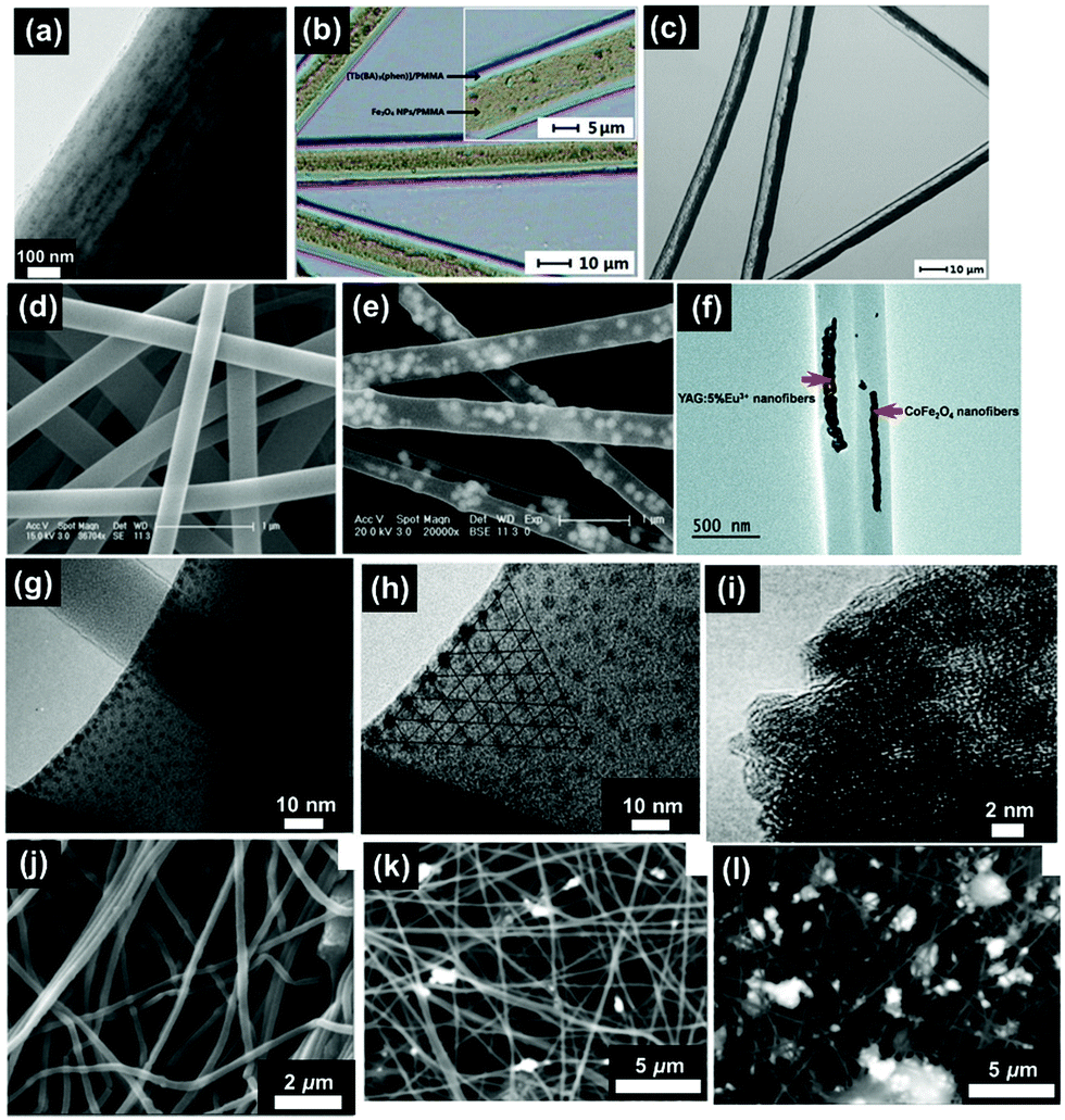 | ||
| Fig. 5 (a) TEM bright field image of a PVP/PLLA/OA–Fe3O4 nanocomposite membrane;73 (b) BM image of [Fe3O4/PMMA] coaxial nanobelts;74 (c) BM image of [Fe3O4/PANI/PMMA]//[Tb(BA)3phen/PMMA] Janus nanoribbons;28 (d) FESEM image of PVP NFs;44 (e) TEM image of α-Fe2O3/europium complex [Eu(DBM)3(Bath), where DBM is dibenzoylmethanate and Bath is bathophenanthroline]/PVP composite NFs;44 (f) TEM image of CoFe2O4/yttrium aluminium garnet (YAG):5% Eu3+/PVP composite NFs;75 reproduced from ref. 75 with permission from The Royal Society of Chemistry; (g) TEM image of strontium hexaferrite nanoparticles (SrM-NPs) embedded in a PVA matrix;76 (h) TEM image of SrM-NPs;76 (i) TEM image of NiZn ferrite nanoparticles;77 (j) SEM image of 1% MGNPs-polymer;78 (k) SEM image of 3% MGNPs-polymer;78 and (l) SEM images of 7% MGNPs-PEO.78 | ||
Fluorescent magnetic NFs have been targeted in research owing to their suitability in a wide range of applications such as; light-emitting diodes,79 sensors,80 resonators81 and full-colour displays.82 However, heavy losses in fluorescent intensity is observed when Fe3O4 NPs are in direct contact with luminescent compounds.69 In order to circumnavigate this problem, core–shell and Janus structures have been produced as they offer the opportunity to incorporate both components in disparate zones of the material; minimising the direct interactions that would typically occur between them. Shao et al.64 reported the fabrication of tuneable fluorescent colour-electrical-magnetic trifunctional coaxial nanoribbons using coaxial electrospinning. These coaxial nanoribbons exhibited similar magnetic properties (Ms of 18.58 emu g−1) to the corresponding composite nanoribbons (where all components were mixed within the ribbons). Most significantly, the fluorescent intensity and electrical conductivity of the coaxial nanoribbons were considerably higher than those of the composite nanoribbons, demonstrating the importance of architecture derived properties. Fig. 5(b) demonstrates the coaxial nanobelt structure, revealing that the core contains large quantities of dark-coloured Fe3O4 NPs whilst the shell of the coaxial nanobelts appears transparent.74
Another effective method to create the Janus structure is via parallel-plate electrospinning. Gai et al.83,84 prepared Janus nanobelts from Fe3O4/PVP and rare earth complex/PVP which demonstrated desired magnetism–luminescence bifunctionality. The Ms ranged from 3.16 emu g−1 to 10.19 emu g−1 and the results suggest that the magnetism can be tuned via different Fe3O4 NP loadings. The Janus nanobelts exhibited superparamagnetic behaviour using Fe3O4 nanoparticles of approximately 15 nm diameter. When the dimensions of the magnetic component, such as magnetite, drop to less than 20 nanometres, its magnetisation direction can flip randomly under the influence of temperature. However, in this circumstance, magnetite becomes superparamagnetic with only one magnetism domain.85 In another example, Ma et al.86 fabricated Janus NFs with Fe3O4/poly(methyl methacrylate) (PMMA) as the magnetic component and the Ms reached 32.61 emu g−1 when the mass ratio of Fe3O4 to PMMA was 6:1. This is similar to Fe3O4/rare earth complex/PMMA composite nanobelts (32.15 emu g−1) that have also been produced.86 However, the fluorescent intensity of the Janus nanobelts is considerably higher than that of the composite nanobelts. Additionally, luminescent–electrical–magnetic trifunctional materials are also a popular target structure in multifunctional nanocomposites. Lv et al.87 added polyaniline (PANI) to the magnetic half of the Janus structure and the electrical conductivity values of the Janus NFs increased with increasing PANI loading. However, the conductivity of the Janus NFs decreased with increasing amounts of Fe3O4 NPs due to the influence of Fe3O4 on the polymerisation process of aniline. The inner structure of the Janus nanoribbons can be revealed by the transmission light of a biological microscope (BM). As shown in the Fig. 5(c), one side of the Janus nanoribbon contains large quantities of dark coloured PANI and Fe3O4 NPs and, by contrast, the other side is transparent.28
Hematite is also often blended with polymeric materials via uniaxial electrospinning. Meng et al.89 produced a paramagnetic nanofibrous composite film with polylactide (PLA), hydroxyapatite and γ-Fe2O3 nanoparticles. The Ms of γ-Fe2O3 NPs was 67.6 emu g−1 whilst the Ms of the film was 0.0492 emu g−1, achieved at a mass ratio of 8.3% γ-Fe2O3 NPs within the film. Alternatively, Khanlou et al.90 prepared γ-Fe2O3 NPs through a chemical co-precipitation process with an Ms of 12.19 emu g−1. Following the chemical co-precipitation, at 5 wt% γ-Fe2O3 NPs, the NPs were added to a PMMA solution. The Ms of the composite produced was then 6.172 emu g−1. Both cases demonstrate that the magnetic properties of MNP blended NFs are not proportional to the mass ratio of MNPs. Polymers do not simply act as a loading matrix but interact with MNPs and mutually influence the overall magnetic properties.
Additionally, there are other iron oxides that can be used to produce magnetic nanomaterials. For example Zhu et al.91 produced core–shell Fe–FeO nanoparticles with an average diameter of 20 nm. The Ms of the Fe@FeO NPs was 108.1 emu g−1 whilst that of the nanocomposite fibres was 30.6 emu g−1; with a nanoparticle loading of 30 wt%. Before electrospinning, the radii of the core and shell was calculated to be 13.2 and 6.8 nm, respectively. However, after electrospinning the radii became 12.7 (core) and 7.3 nm (shell). The shell thickness increase was attributed to an increase in particle oxidation at the extremely high voltages used during the electrospinning process.
Finally, Murillo-OrtÍz et al.76 embedded strontium hexaferrite nanoparticles (SrM-NPs) in PVA NFs. The ratio of Mr/Ms increased by 81 when 30 wt% SrM-NPs were added to the PVA solution. As observed in Fig. 5(g), these nanoparticles have uniform size and have a localised distribution of NPs inside the surface of the NFs. Additionally, they do not show the presence of agglomerates. Fig. 5(h) then shows that the nanoparticles are ordered on the surface of the fibre and aligned with respect to the NFs’ growth. This is a consequence of the nanoparticles’ interaction with the highly intense electric field aligned with the electrodes in a point-plate configuration.
Chen et al.94 synthesised and modified CoFe2O4 nanoparticles to improve dispersion. The diameter of the CoFe2O4 particles produced was 5 nm and the Ms achieved was 50 emu g−1. The diameter achieved is smaller than that of the bulk materials, due to the size of the CoFe2O4 crystallites and fewer defects being present in the structure. Finally, the CoFe2O4 NPs were mixed with polyacrylonitrile (PAN) and the composite exhibited an Ms of 45 emu g−1. The decrease in Ms is attributed to the non-magnetic material coating (PAN) and its influence on the uniformity and magnitude of magnetisation by extinguishing the surface magnetic moment. Alternatively, Wang et al.95 fabricated Janus NFs using CoFe2O4 to achieve magnetism–luminescence bifunctionality. When the mass ratio of CoFe2O4:PAN was 1:3 the Ms and Hc achieved were 5.09 memu g−1 and 20 kOe, respectively. Additionally, Bi et al.75 electrospun [Fe(NO3)3 + Co(NO3)2]/PVP precursor solution before annealing in air at 700 °C for 4 hours to prepare CoFe2O4 NFs. YAG:5% Eu3+ calcinated NFs were also prepared via the same method. Janus NFs were then fabricated from both the CoFe2O4 NFs/PVP and YAG:5% Eu3+ NFs/PVP solutions, as shown in Fig. 5(f). The Ms of the CoFe2O4 NFs was 41.34 emu g−1 whilst the Ms of the Janus NFs ranged from 3.12–20.32 emu g−1. The observed enhanced performance is attributed to the isolation of YAG:5% Eu3+ luminescent NFs from the CoFe2O4 magnetic NFs. Gonçalves et al.96 prepared composite fibres of CoFe2O4 and poly(vinylidene fluoride) (PVDF). The composites demonstrated an increase in magnetisation with increasing CoFe2O4 content. They also found that the piezoelectric coefficient of the NF composites increased with increasing applied magnetic field. This is a result of the strain-mediated coupling between the magnetostrictive CoFe2O4 nanoparticles and the piezoelectric PVDF matrix. However, when compared with bulk polymers the piezoelectric coefficients were lower. It is speculated that this reduction is due to clamping by the surrounding material; which may significantly reduce the local deformation of the NFs.
Ghanbari et al.97 synthesised CaFe2O4 nanoparticles that exhibit ferrimagnetism before producing cellulose acetate (CA)–Ag–CaFe2O4 nanocomposites by electrospinning. The Ms, of the nanoparticle compared to the NF, decreased from 6.1 to 0.31 emu g−1 whereas the Hc increased from 40 to 78 Oe, respectively. The authors stated that the magnetic moments of the CaFe2O4 nanoparticles are pinned by the polymer chains so that a higher magnetic field is required to align the single domain nanoparticles in the field direction. Additionally, Khan et al.77 prepared Ni0.6Zn0.4Fe2O4 nanoparticles (see the transmission electron microscopy (TEM) image in Fig. 5(i)) with Ms of 26.81 emu g−1. The NPs were then incorporated into composite NFs [with carbon nanotubes and recycled polystyrene (PS)] at 7.5, 15, and 30 wt% to produce fabrics with Ms values of 2, 4, and 8 emu g−1, respectively.
Erfan et al.78 prepared ferrimagnetic glass ceramics, with a diameter of 10 nm, through the use of high-energy ball milling. The Ms of the magnetic glass ceramic nanoparticles (MGNPs) was 53 emu g−1 and the Hc equal to 88 Oe. The Ms of the composite fibre reached a maximum of 4.16 emu g−1 when the mass ratio of MGNPs was 7%. Low MGNPs concentration (1 wt%) NFs (Fig. 5(j)) appear clear and smooth, however, the roughness and nanoparticle aggregation on the surface of the NF increased at higher MGNP content (Fig. 5(k) (3 wt%) and 5 (l) (5 wt%)).
Min et al.100 fabricated PVA/ferritin superparamagnetic fibres. The interaction between the host PVA hydrogel and the protein shell on the ferritin bio-nanoparticles was controlled by thermal methods to vary the size and concentration of the ferritin clusters. The average size and concentration of the ferritin clusters increased in the PVA NFs when the mixing temperature was raised from 30 to 80 °C. The close proximity of the ferritin cores within the clusters resulted in magnetic ordering and increased magnetisation in some cases.
Additionally, many research groups are now developing novel magnetic nanomaterials. One example is FePt which has demonstrated good chemical stability and high magnetocrystalline anisotropy.101 Another example shows micron size graphene sheets decorated with cobalt NPs to endow magnetism.102 There has also been an increasing focus on producing composite fibres with a range of polymeric materials. However, the mechanism regarding the interaction between the magnetic nanoparticles and polymer materials remains unclear.
3. Electrospun fibrous templates
This section discusses the various approaches used to create magnetic nanofibrous materials by electrospinning template constructs and the post-spinning treatment used: (i) deposition of magnetic NPs; (ii) carbonisation; and (iii) calcination. Fig. 1(b and c) highlights the different routes that have been used in this area of research. Table 2 serves as a comprehensive summary of this section, listing the various systems that have been explored, the magnetic reagent(s), polymer(s), electrospinning and processing approach, the final morphology obtained, major magnetic property and applications (where relevant) in each case.3.1 Product morphology and corresponding processing
The template method is a cost-effective and scalable route used to produce both pure inorganic magnetic NFs and organic–inorganic hybrid magnetic NFs. Electrospun fibrous templating is also a convenient method for inorganic magnetic nanofibre (MNF) fabrication and the MNFs produced sometimes exhibit an increase in Ms.103 However, the change in Ms depends on a range of complex factors and is not always enhanced. The appearance of a magnetically inert layer in the fibrous structure,104 the formation of ferromagnetic phase105 and smaller grain size are all factors that may contribute to a decrease in Ms in 1D nanostructures prepared by the electrospun fibrous template method.106 The templating procedure of the MNFs (Fig. 1(b and c)) generally encompasses two steps: electrospinning to create a fibrous template followed by post-treatment of the template. A typical template-assisted electrospinning precursor solution is made up of three parts: (i) a magnetic component; (ii) polymer(s); and (iii) a solvent system. The magnetic component is typically in the form of magnetic nanoparticles (MNPs)107 or metal salts. Polymers are added to the system to meet the viscosity demand of electrospinning (i.e. to provide entanglements). The most widely used polymers include PANI,108 poly(ethylene oxide) (PEO),109 polyurethane,107 PVA,110 PAN,111,112 and PVP.48,113–116 The purpose of the solvent is to dissolve the polymer(s), disperse or dissolve the magnetic component used and improve the charge-carrying capacity of solution. Typical solvents used are DMF, dichloromethane (DCM), methyl ethyl ketone (MEK), deionised water, ethanol116 or a combination thereof.107 The viscosity, concentration, surface tension and dielectric properties of the spinning solution exert a great influence on the electrospinnability of the solution and the diameter, morphology, crystallinity and tensile strength of the NFs. Such influences have been referred to in previous studies.117,118 Finally, Fig. 1(c) highlights an alternative route where NFs without any magnetic components are used as templates before MNPs are deposited upon them.In the sol–gel process, literature reports have demonstrated the use of metal nitrate114,116,119 and acetate114 precursors with polymer(s) in the production of electrospun NFs with uniform distributions, even at very high loadings.120 Although the mechanisms for such processes were not explicitly discussed, the conditions in which the precursor solutions were prepared are reported.48,121,122
Following initial deposition, the obtained fibres are often dried and pre-sintered to evaporate any solvents.94,114–116,119,121,123 This is followed by calcination, at a given heating rate, in order to (partially or completely) remove the polymers to form pure inorganic fibres. Concomitantly, the metal ions are converted to their neutral elemental state48 and the atoms aggregate to form nanoparticles.124 The calcination conditions are adapted to meet the varying demands of a given system. For example, air is an idealised atmosphere if metal oxide NFs125 are targeted, whereas hydrogen (H2),126–128 often in combination with an inert gas such as argon (Ar),129–132 and ammonia gas (NH3) are adopted as a reduction (often referred to as de-oxidation in the literature) source. In some cases, the calcination atmosphere is selected to generate oxygen vacancies or eliminate impure phases.133 For example, α-Fe2O3 NFs obtained in a study by Guo et al.134 were heated in an NH3 atmosphere and the crystallites were transformed into Fe3O4 crystallites. Additionally, when the temperature was raised, Fe2N NFs were obtained. The electrospinning parameters, environmental conditions, physical and electrical properties of the spinning solution, and calcinating conditions (temperature, rate, profile and duration) all enable the crystal structure, morphology and ultimate properties of the final product to be manipulated.135 For example, the preparation of mullite–nickel nanocomposite NFs132 was performed through two heating stages. The first was used to convert Ni2+ to Ni NPs in a reducing atmosphere between 550–750 °C before the mullite phase was formed at 1000 °C. However, if the first stage was not allowed to proceed for sufficient time (to permit Ni2+ to be fully reduced to Ni NPs), an undesirable spinel phase mixed with a mullite phase was formed during the second heating stage. In a similar procedure, a Fe/Ni alloy was prepared from the reduction of NiFe2O4 (300–600 °C) to produce Fe–Ni alloy nanoribbons.126,136 The morphology of the Fe–Ni alloy precursor (body-centred cubic or face-centred cubic) was influenced by the heating temperature used during the reduction stage.
Often the calcinated products are formed as powders and do not maintain their structure.41 Efforts have been made to resolve this problem by shifting towards the production of fibre mats that offer the added benefit of being flexible, easy to produce, recyclable and cost-effective. In one example, flexible fibre mats have been utilised in the development of magnetic devices; offering a new design method for electromagnetic shielding systems.121 Additionally, the ease of recycling the mats and the enhanced structural stability, when compared to powders, is highly desirable in applications such as waste water treatment.118 The key factors that influence the flexibility of these fibrous mats are the uniform distribution of NPs throughout the NFs,110 the porous structure of the mats110 and the interfacial energy between NPs and NFs.110 Consequently, attempts have been made to improve the interfacial interactions between the MNPs and the matrix.94 For example, zein (a maize protein) was used as an adhesive between NiFe2O4 NPs and SiO2 NFs to render the resultant fibre mats with extraordinary flexibility.110 In addition, Wang et al. reported that oxygen plasma treatment was an effective way to keep the membrane integrated during the stage where the organic component is removed.41 Finally, flexible calcinated γ-Fe2O3/C NF mats have also been prepared by combining electrospinning, hydrothermal synthesis and calcination.121,137
NFs with different morphologies can also be fabricated by changing the shape of the liquid supply nozzle or by adjusting the calcination parameters used to remove the polymer construct. In the first stage, when polymers are present, fibres decorated with inorganic particles are obtained. Once the polymers have been removed, necklace like NFs, short NFs, nanobelts, core shell NFs, hollow NFs and regular NFs can be obtained. Fig. 6 shows the various types of MNFs that can be targeted by electrospinning, as discussed in the following sections.
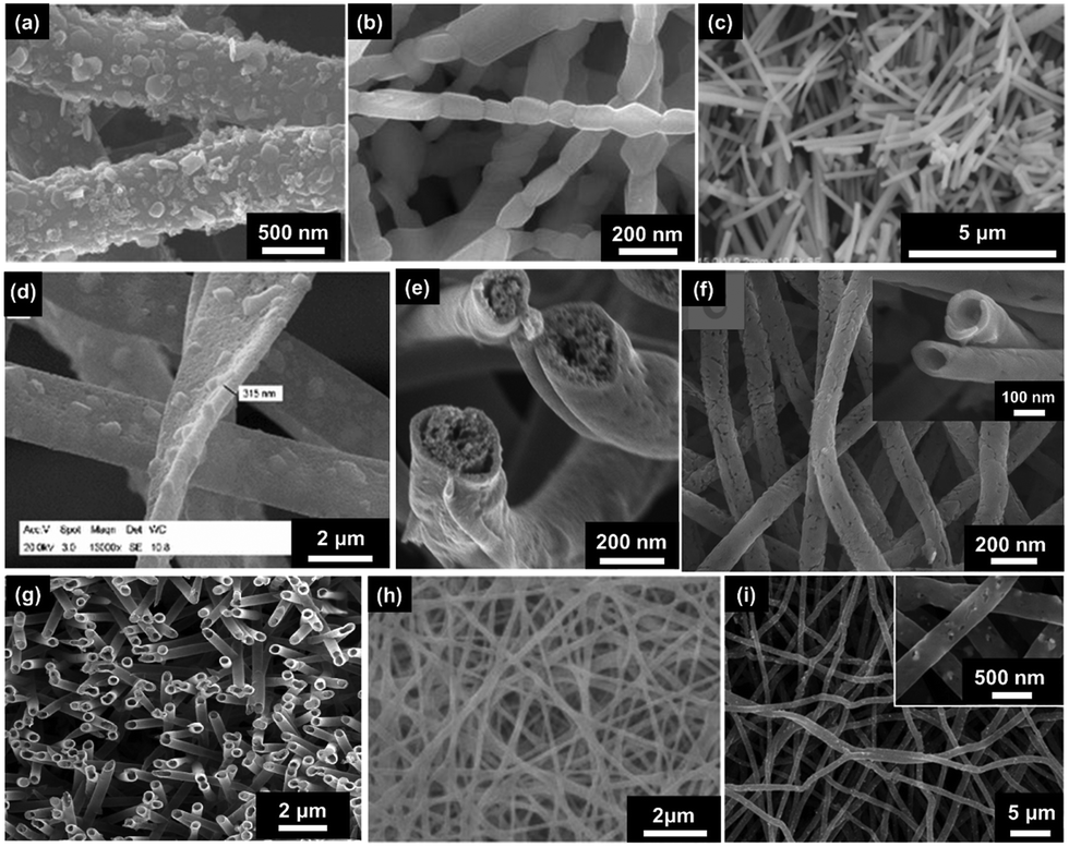 | ||
| Fig. 6 Example SEM images of: (a) fibres with particle deposition;107 (b) necklace-like NFs;138 (c) short NFs;139 (d) nanobelts;111 (e) core–shell NFs;140 reproduced from ref. 140 with permission from The Royal Society of Chemistry; (f) hollow NFs;134 reproduced from ref. 134 with permission from The Royal Society of Chemistry; (g) nanotubes;141 reprinted with permission from ref. 141. Copyright (2021) American Chemical Society; (h) 3D crosslinking NFs;109 and (i) regular NFs (calcinated).142 Specific details: (a) Fe3O4@PU NFs, Fe3O4 NPs at 1 mg ml−1; (b) SrFe12O19 NFs calcinated at 1000 °C; (c) BiFeO3 NFs calcinated at 550 °C; (d) Fe3O4/C NFs calcinated at 800 °C; (e) CoFe2O4–Pb(Zr0.52Ti0.48)O3 NFs calcinated at 750 °C; (f) Fe2N NFs calcinated at 400 °C; (g) SnO2 NFs calcinated at 500 °C; (h) Fe3O4–alginate (SA)/PVA crosslinked NFs; and (i) NiFe2O4/multi-walled carbon nanotube (MWCNT) carbon-based NFs (CNFs) calcinated at 850 °C. | ||
Nanotubes (Fig. 6(g)) are similar in structure to hollow fibres and the differences between them are subtle and sometimes difficult to identify.163 In some cases, the term ‘nanotube’ is used to describe shorter, defect-free hollow fibres, but there is no clear definition and the term tends to be used interchangeably with hollow NFs across the literature. Accurate heating methods are required for nanotube construction via single nozzle electrospinning and Jiang et al. has reported the successful synthesis of nanotubes several microns in length.164 Additionally, Li et al. obtained NaYF4:Yb/Er/Gd-decorated SiO2 nanotubes via single nozzle electrospinning followed by calcination using a spinning solution comprised of NaYF4:Yb/Er/Gd nanocrystals, TEOS and PVP. The as-spun NFs were annealed between 200–600 °C at a heating rate of 2 °C min−1. In this example, PVP is forced to migrate to the surface once leaving the nozzle resulting in a PVP–silica shell with the magnetic component and TEOS within the core. Upon removal of the organic material, nanotubes were produced.165
In the coaxial spinning procedure, the pure organic part (such as mineral oil, polymers or components that incorporate magnetic ingredients166) can be adopted as the core solution.167 However, the flow rate of the inner solution should be controlled to prevent leakage.166
In addition to the aforementioned traditional single-walled hollow structures, there are novel structures that have been obtained, such as hollow-core–double-shell NFs. Kim et al.158 produced CoFe2O4 core–PANI double shell structures. Initially hollow CoFe2O4 NFs were obtained by calcinating the precursor fibres between 80–550 °C at a heating rate of 5 °C min−1 for 2 hours. The inner and outer surfaces were then coated with PANI via in situ oxidative polymerisation.
3.2 Processing parameters and magnetic properties
The most common processing parameter for electrospinning NF templates is calcination. Calcinated NFs still possess superior magnetic performance than their zero-dimensional (0D, i.e. nanoparticles) or bulk counterparts. The most apparent property enhancement is in the coercivity (Hc) due to the anisotropic nature of NFs, as compared to NPs.127 The magnitude of the coercivity is related to the anisotropy of the material, which includes magneto-crystalline anisotropy, shape anisotropy and stress anisotropy. However, the NF structure possesses large shape anisotropy as a result of the strict restriction of magnetic moment along the fibre axis.170 For example, LaFeO3 exhibits antiferromagnetism in the bulk, yet is ferromagnetic when in processed as a one-dimensional (1D) nanostructure with an increased coercivity value of 28000 Oe.171 In addition, 1D hard–soft exchange-coupling nanomaterials offer a unique platform for enhancing the maximum magnetic energy product [(BH)max] due to the reduced self-aggregation when compared to their 0D counterparts.124,154 In another case, Lee et al.154 fabricated core–shell Sm2Co17/FeCo NFs by electrospinning, calcination, calciothermic reduction and electroless plating. Relative to its 0D counterpart, the well-dispersed 1D/core–shell nanostructure demonstrates an enhancement in (BH)max (46% increase) as a result of the dense homogeneous soft magnetic coating as shown in Fig. 7. However, it should be noted that the magnetic properties are not always improved by simply introducing anisotropy (going from nanoparticles (0D) to NFs (1D) nanomaterials). This was highlighted in a study where the Ms value of CoFe2O4 NFs was lower than that of CoFe2O4 NPs and even the bulk counterparts.172
 | ||
| Fig. 7 Scheme of expected magnetic performance in a uniform, one-dimensional, hard–soft magnetic core–shell nanocomposite and its counterpart.154 Adapted with permission from ref. 154. Copyright (2021) American Chemical Society. | ||
3.2.2.1 Calcination temperature. The relationship between calcination temperature and Ms is often system dependent. Generally, for a given system, lower thermal treatment temperatures result in smaller particles being formed (down to a critical minimum size) and the smaller particles exhibit smaller Ms values.106,114,119,122,132,133,170,172,176–188 Larger particles have less magnetic contribution from the surface (whilst the contribution from the interior concomitantly increases) and thus the Ms value increases.114 However, the smaller Ms values observed at low calcination temperatures are not always only due to the decrease in size of the particles. For example, in Liu's study, the CoFe2O4 NFs were calcinated at 700, 750, 800, 850 °C, respectively. In addition to the increase in particle size, the XPS results suggested that as the calcination temperature increases, the migration of cobalt ions to the tetrahedral sites as well as iron ions to the octahedral sites increases, thus also contributing to the larger Ms observed.189 However, there are examples that do deviate from this trend. For example, the Ms values of CuCo2O4 fibres have been found to decrease with increasing calcination temperature.190 In this case, the decrease is attributed to surface distortions brought about by interactions between oxygen atoms and transition metal ions. Ti0.9V0.1O2 NFs were also shown to exhibit a decrease in Ms with increasing heat treatment temperature, which was assigned to the increase of nearest-neighbour V ions with direct antiferromagnetic coupling.191
In the study of Liu et al., the Ms value of α-Fe2O3/TiO2 NFs decreased with increasing calcination temperature. The authors ascribed this to an increased density of α-Fe2O3.177 The decrease in Ms with arising calcination temperature was also found in other studies.192 In more recent work, Ponhan et al.193 determined that the Ms dependency on calcination temperature of ZnFe2O4 NFs exhibits through both of the observed trends. Initially, Ms increases with calcination temperature before then decreasing, with crystallite size increasing typically from 19 to 26 nm.
Similarly, the Hc transition with calcination temperature is also system dependent. In most cases, Hc increases with calcination temperature; including that observed for MgFe2O4 nanotubes,135 CoFe2O4 NFs,194 NiFe2O4 NFs,183 MnFe2O4 NFs,186 Ni/mullite NFs132 and Co0.5Ni0.5Fe2O4 NFs.122 However, there are also reports where the Hc transition does not follow this trend. For example, the Hc value of MnFe2O4/C NFs decreases with increasing calcination temperature185 and is attributed to the MnFe2O4/C NFs exhibiting ferromagnetic properties due to the distribution of cations over tetrahedral and octahedral sites. In the study by Lu et al.,106 the Hc value of CoFe2O4 NFs demonstrated an initial increase followed by a decrease with increasing annealing temperature. The same phenomenon was reported in both SrTiO3/SrFe12O19 NFs181 and yttrium iron garnet NFs,170 attributed to the motion of domains experienced at different particle sizes. Furthermore, the same trend was found in hollow CuFe2O4 NFs.159 In this case, higher calcination temperatures gave rise to larger MNPs and thus a higher field force was required to alter the magnetic moment direction; in turn resulting in higher Hc. However, when the particle size exceeded the critical size for a single-multi domain transition, Hc declined. Findings from the study of CoFe2O4 hollow fibres further support this claim as Hc increases with annealing temperature.160 The Hc value of the CoFe2O4 nanobelts119 achieved a maximum value of 1802 Oe before decreasing with further increases in calcination temperature as a result of the particle size being below the critical domain size. In addition, the absence of domain walls and unique rectangular cross-sectional shape contributed to the high magneto-crystalline properties observed.
The final important magnetic property to be discussed in relation to calcination temperature is remanent magnetisation, Mr. In one example, CoFe2O4 NFs, fabricated by single spinning and calcination, and were shown to exhibit a uniform increase in Mr with increasing calcination temperature. This is commonly attributed to an increase in the particle size.194 The same phenomenon was found for MnFe2O4 NFs,186 SrTiO3/SrFe12O19 NFs,181 MgFe2O4 nanotubes,135 hollow CuFe2O4 NFs159 and hollow CoFe2O4 NFs.160 In one contradictory case, the Mr value of CuCo2O4 fibres190 was found to decrease with increasing calcination temperature, which was suggested to be due to weakening of the superexchange interaction between the Cu3+ and Co2+ cations.
In some fabrication methodologies, the heat treatment encompasses two stages; calcination and reduction. The magnetic properties are known to be dependent on the reduction temperature. For example, the reduction temperature of Fe/Ni alloy nanobelts126 show an increase followed by decreasing trend in Ms, whereas the Hc initially decreases before remaining almost constant with increasing temperature. In this example, the Fe/Ni alloy nanobelts were reduced from NiFe2O4 and the initial relative low temperatures used resulted in the observed partial reduction of Ms.
The relationship between calcination temperature and Ms, Hc and Mr has been identified as significantly system dependent. Factors such as density, surface distortions, cation distribution, particle size and cation interaction have all been shown to contribute to the final magnetic properties of the NFs produced.
3.2.2.2 Calcination atmosphere. The calcination atmosphere used can have a significant effect on the magnetic properties of NFs. For example, SrFe12O19/CoFe2O4 obtained from as-spun NFs calcinated in air showed a Hc value of 3190 Oe. On the other hand, SrFe12O19/FeCo obtained from as-spun NFs calcinated in air and then reduced in hydrogen showed a significantly lower Hc value of 1249 Oe. This change is attributed to the close contact of the soft and hard phases which in turn results in strong exchange coupling. In addition, Fe2O3 hollow NFs obtained from as-spun NFs calcinated in air were superparamagnetic and achieved an Ms value of 4.34 emu g−1, whilst Fe3O4 and Fe2N hollow NFs obtained from as-spun NFs calcinated in air and then reduced in gaseous ammonia achieved Ms values of 82.99 emu g−1 and 2.07 emu g−1, respectively. Finally, the Fe3O4 hollow NFs exhibited ferromagnetism whilst the Fe2N hollow NFs demonstrated superparamagnetism.134,153 The morphology of the fibre can also be altered depending on the calcination atmosphere used and, as previously discussed, is directly related to the magnetic properties of the final fibre. In one example α-Fe2O3 nanotubes and Fe3O4 NFs were produced when the calcination atmospheres were air and argon, respectively. Nanotubes were formed due to the lack of oxygen present as gas diffusion from the decomposed organic component (PEO) drives the nanoparticles from the inside to the outside of the fibres.195
Moreover, carbonisation often induces the transformation from superparamagnetism to ferromagnetism in electrospun NFs.194 This is due to the formation of a new phase, such as the carbide crystal, which destroys the single crystal domain of the original NFs.172 It has also been claimed that enhancement of particle size leads to higher magnetocrystalline anisotropy.197,198
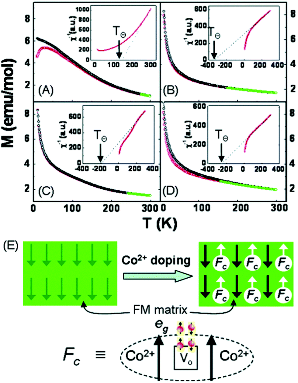 | ||
| Fig. 8 The effect of doping ZnO NFs with Co2+ on magnetic properties, illustrated through: (A)–(D) temperature-dependent magnetisation (M–T) curves of Zn1−xCoxO (x = 0, pure ZnO nanowires) NFs with 1.8, 4.4 and 7.2% Co, respectively. This visually shows the transition from ferromagnetism to ferrimagnetism. (E) Co2+ doping-induced ferromagnetism to ferrimagnetism crossover.218 Reproduced from ref. 218 with permission from The Royal Society of Chemistry. | ||
Doping has also been known to lead to the production of NFs with unique properties. For example, hole-doped manganites, with the general formula R1−xAxMnO3 (where R refers to a trivalent rare earth element and A is a divalent alkaline earth element) were found to exhibit colossal magneto resistance (CMR). La0.33Pr0.34Ca0.33MnO3 NFs (prepared at a calcination temperature of 600 °C) exhibited CMR over a wide temperature range and the magneto resistance reached a maximum value of 95% at the metal–insulator transition temperature of 70 K under 7 Tesla.219 In another case, doping α-Fe2O3 nanotubes with V2O5 was found to increase Ms, and decrease Hc, which was attributed to the aforementioned Brown's theory; where Hc and Ms are inversely proportional to one another.217 In other work, after Co doping, SrTiO3 was endowed with room temperature ferromagnetism due to Co addition and oxygen vacancies,130,173 which has also been demonstrated in the study of SnO2 nanotubes.220 However, Mohanapriya et al. suggests that ferromagnetism in Mn-doped SnO2 NFs is induced only by precipitated impurity phases instead of pure SnO2 or dopant.221 Nevertheless, Mn doping was found to impair the ferromagnetism of BaTiO3 and resulted in dia- and paramagnetic behaviour of the BaTi0.9Mn0.1O3 NFs that were produced.222 Fe-Doped NiO NFs were prepared as a diluted magnetic semiconductor (DMS) and, notably, doping was shown not to affect the fibre diameter or surface morphology.223 Finally, the addition of GO dopant to CoFe2O4 NFs demonstrated enhanced crystallinity, which boosted Ms values at low loadings, but was then shown to exhibit a slight decrease in Ms with higher GO loadings.224
4. Applications
In this section, the application of magnetic materials, and how this relates to their final properties, are explored. This aptly highlights the versatility of electrospun magnetic materials whilst concomitantly highlighting the need for future work into their production and design.4.1 Electromagnetic shielding/absorption
With the extensive utilisation of electronic devices for civil and military purposes there is a strong desire to reduce electromagnetic (EM) pollution due to its associated negative impact on human health, national defence security and electronic safety.121,226–231 EM wave shielding, or absorption materials, are designed to address this challenge. Fig. 9 shows a schematic diagram that illustrates the working mechanism of so-called microwave absorption materials (MAMs). When incident waves reach the surface of the material, they are either reflected off the sample or transmitted into a porous channel; where multiple reflections occur and the energy is dissipated. The difference between MAMs and electromagnetic-induced (EMI) shielding materials is that MAMs require EM waves to be transmitted into the materials to be dissipated rather than simply reflected at the surface.150,196 MAMs achieve EM attenuation through a combination of magnetic loss, electric loss and geometry (morphology).226,228 Magnetic loss originates from the eddy current effect, natural ferromagnetic resonance and exchange resonance. For ferromagnetic materials, the magnetic loss ability is related to initial permeability (μi), as shown in eqn (1), where a and b represent constants relating to the material being used, and λ, k, ξ, Ms and Hc are the wavelength, magnetisation constant, elastic strain parameter of a crystal, saturation magnetisation and coercivity, respectively. Eqn (1) shows that high Ms and low Hc values are required to increase μi, to deliver better magnetic loss ability.226,232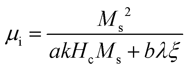 | (1) |
 and
and  , respectively.196,226,228
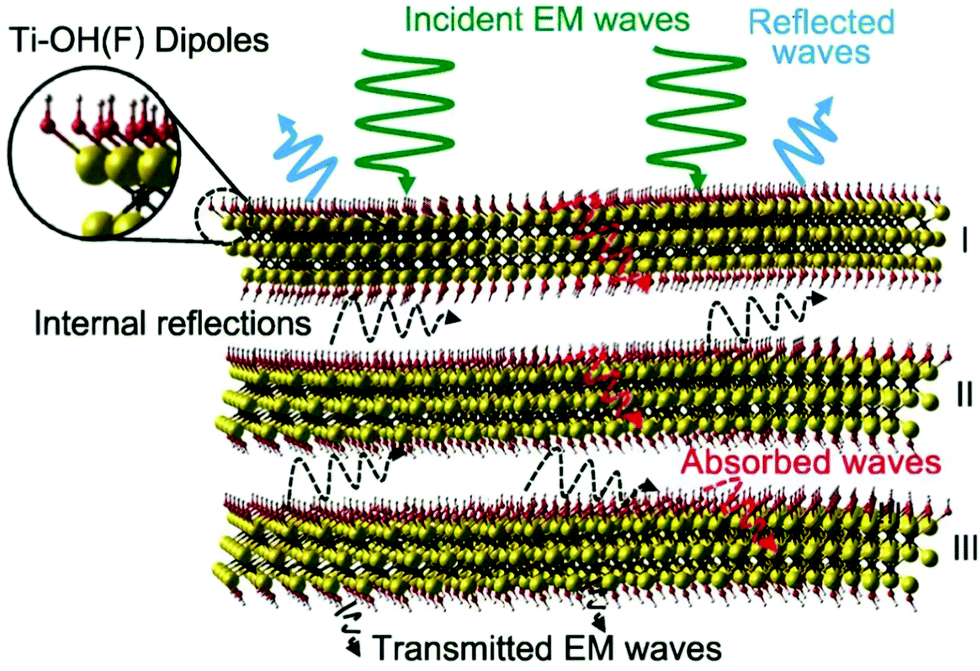 | ||
| Fig. 9 Electromagnetic wave attenuation through a shielding material.233 | ||
Reflection loss (RL) is calculated from eqn (2)–(4):196,226,228
 | (2) |
 | (3) |
 | (4) |
Carbon fibres can be equipped with magnetic properties through the addition of MNPs to create EM absorbing materials. The ultimate EM wave absorption capability is a direct result of both the dielectric and magnetic properties, with higher Ms and lower Hc values also contributing to the magnetic wave absorption properties.226,228 Notably, NiFe2O4/multi-walled carbon nanotubes (MWCNTs)/carbon nanofibrous membranes, with thicknesses of 2–5 mm, have been created as MAMs that achieve high permeability and reflection losses >20 dB (5.36–18 GHz).142
4.2 Separation: pollutant treatment and catalysis
Functional pollutant absorbers and photocatalysts are used extensively in wastewater treatment. However, the challenge on how to avoid secondary pollution of any residual absorber or catalysts remains a significant problem. One method used to address this issue is the incorporation of electrospun NFs with unique magnetic properties. After degradation, these materials are easily recycled by use of a permanent magnet.45,158,166,177,199,200,202,234–247 For example, Liang et al.248 prepared multifunctional switchable chemosensors for Hg2+ with fluorescent probe 1-benzoyl-3-[2-(2-allyl-1,3-dioxo-2,3-dihydro-1H-benzo[de]isoquinolin-6-ylamino)ethyl]-thiourea (BNPTU), PNIPAM copolymer moiety for thermo-responsiveness and on–off photoluminescence and Fe3O4 NPs for easy removal. Chang et al. deposited bismuth oxyiodide nanoflakes on α-Fe2O3 NFs via the SILAR (successive ion layer absorption and reaction) method.237 The final product reached a maximum specific surface area of 35.27 m2 g−1, rhodamine B degradation efficiency of 98% after 2 hours of visible light irradiation and an Ms value of 0.9 emu g−1, demonstrating its potential for use as practical separable photocatalysts. As these MNPs render the fibres ferromagnetic, or superparamagnetic, they can be attracted to external magnetic fields.239,249–251 In addition to this, it has been shown that under stronger magnetic fields the catalysts can be demulsified and therefore recycled back for reuse.2524.3 Tissue engineering scaffolds, cell culture and differentiation
Electrospun NFs have been extensively explored as scaffolds for regenerative medicine. Recently, superparamagnetic fibrous scaffolds have been discovered to have a positive effect regarding cell differentiation (Fig. 10). Furthermore, after implanting the scaffold into the human body, the magnetic property enables the device to be manipulated remotely. The most common approach in this area is to combine MNPs, such as γ-Fe2O3,253–255 Fe3O4,8,85,256–259 CoFe2O4 and bioglass,260 with bio-compatible polymers [such as PVA,253–255,260 polycaprolactone (PCL), poly(L-lactide), poly(lactic-co-glycolic acid) (PLGA), poly(succinimide) and poly(aspartic acid)8,85,256–259] to create flexible composite fibrous mats. These mats have been shown to exhibit enhanced mechanical properties compared to pristine non-magnetic NF mats. NFs with a dense, uniform, surface coverage of MNPs are targeted, however, their production remains a challenge.144,242 | ||
| Fig. 10 Schematic showing the mechanism and effect of the IONP-assembled electrospun scaffold on the cells.144 Adapted with permission from ref. 144. Copyright (2021) American Chemical Society. | ||
There have been attempts to employ electrospun fibrous templates to create tissue engineering scaffolds, where such methods appear to facilitate better distribution of MNPs on the surface of the NFs. For example, the layer-by-layer assembly technique was used to afford virtually continuous, compact and uniform α-Fe2O3 nanoparticle immobilisation on PLGA/PCL electrospun scaffold surfaces.144 In this example, the superparamagnetic scaffold was found to significantly enhance the differentiation of adipose-derived stem cells for the treatment of osteogenesis. Moreover, the capping layer brings about auxiliary benefits such as hydrophilicity, elasticity of the interface and the affinity for stem cells. In other work, composite Fe3O4/silk fibroin NFs were compared to silk fibroin fibrous templates with coated Fe3O4 NPs to show the effect of the fabrication method on the final properties of the fabrics. The composite material (electrospun from a single solution) was more effective as a cell scaffold whilst the fibrous mat coated with MNPs was more suitable as a magnetic-sensitive interface.8
4.4 Hyperthermia treatment
The treatment of cancer cells includes chemotherapy, radiation therapy and surgery. Whilst these treatments have been used for decades it has been suggested that methods typically used to treat hypothermia could be an effective and ideal approach. This is based on the incorporation of superparamagnetic NFs which can either give out a fatal amount of heat to kill the cancer cells or the raised temperature of targeted tissues can enhance the effects of other therapy (such as drug release as shown in Fig. 11) used to destroy the cancer.107,109,145,261,262 Superparamagnetic fibres produce a thermal effect in response to an applied alternating magnetic field. The significant advantage of superparamagnetic NFs is their demagnetisation in the absence of an external field. Non-toxic, biodegradable polymeric matrices109 serve as carriers to provide mechanical support alongside other performance-enhancing properties, such as inhibiting the overgrowth of malignant tissues.107 The further merit of NFs in biomedical applications lies with their large surface area-to-volume ratios that lead to faster degradation of the scaffold after they have served their purpose. A large ratio of superparamagnetic NPs relative to polymer is required to provide an adequate number of accessible sites and immobilise the NPs on the NFs.145 There are reports where the number of MNPs on fibres have been quantified. Chen et al. used Fe2+ to chelate with alginates before fabricating a crosslinked Fe3O4–SA/PVA mat by chemical co-precipitation. Immobilising the NPs on the fibre was then shown to eliminate cytotoxicity effects towards human lung fibroblast cells.107,109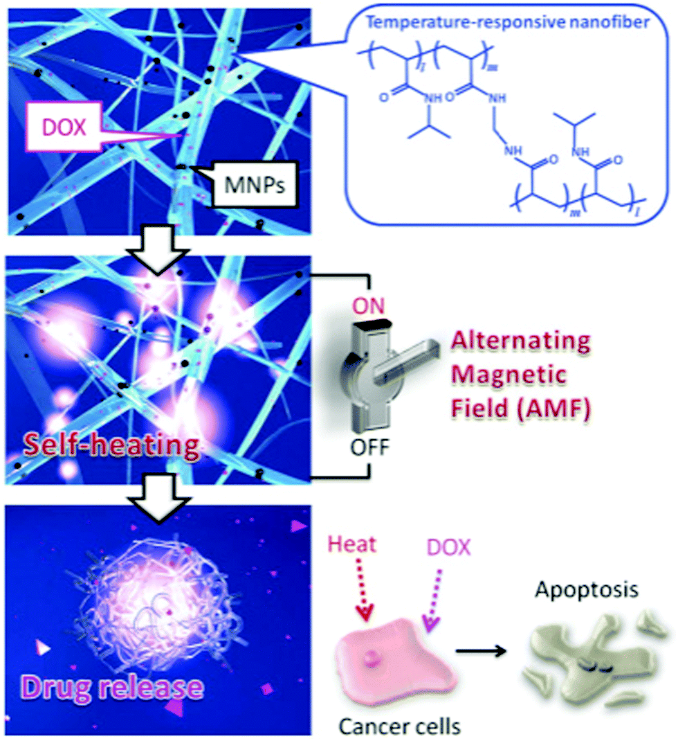 | ||
| Fig. 11 Design concept for a smart hyperthermia NF system that uses MNPs dispersed in temperature-responsive polymers.1 | ||
4.5 Drug delivery
Recent developments in nanotechnology have led to polymeric matrices (e.g. NFs) being exploited as controllable drug release media.263 Encapsulating bioactive agents in a polymer matrix is an effective method for preventing drug degradation in potentially hostile environments (e.g. high or low pH). Electrospun ultrathin fibres exhibit ideal characteristics such as high porosity, large surface area and diverse controllable morphologies to facilitate the development of electrospun fibrous drug delivery systems.88,264For example, a core–shell fibrous drug delivery system was produced by coaxial electrospinning using Eudragit S100 as the shell and a core composed of PEO loaded with Gd(DTPA) (gadolinium diethylenetriamine pentaacetate hydrate, magnetic resonance contrast agent) and indomethacin (model therapeutic agent).265 Eudragit is insoluble in acidic environments and when used as oral medication protects the core ingredient as it passes through the stomach. The core materials are only released when the fibres reach the intestinal fluids, enabling this core–shell fibre delivery system to achieve targeted drug delivery to the colon. In another example, PVA/ferritin NF hydrogels with controllable magnetic properties were fabricated by partially unfolding the ferritin protein shell at varied mixing temperatures.100 The negative image contrast generated by ferritin in the PVA matrix under MRI provided a method for in vivo imaging of the tissue-engineered scaffolds.
Meanwhile, magnetic reagents loaded into electrospun fibres have been shown to demonstrate synergistic effects. Sasikala et al.266 designed and synthesised an implantable magnetic nanofibrous device for hyperthermia treatment comprised of iron oxide nanoparticles and tumour-triggered controlled drug release (bortezomib). The fibres exhibited a synergistic anticancer effect by applying the hyperthermia treatment and drug delivery simultaneously. In other work, a similar design was employed by embedding MNPs (as heat generators) and DOX (doxorubicin, anticancer drug) inside a temperature responsive copolymer of poly(N-isopropylacrylamide)-co-(N-hydroxymethylacrylamide) [P(NIPAM-co-HMAAm)].1 When placed in an alternating magnetic field, the crosslinked P(NIPAM-co-HMAAm) NF mesh showed reversible changes in swelling, which created an ‘on–off’ response allowing DOX to be released.
Beyond their use in externally triggered controlled release, the addition of MNPs can have a varied effect on drug release rate, depending on how the MNPs impact on the system within which they are placed. Demir et al.267 found that RhodB (hydrophilic dye) loaded in PCL NFs was released faster when MNPs were present due to the magnetic interaction between the nanoparticles and drug. Similarly, Haroosh et al.268 also found that the addition of MNPs increased drug release rate. In this case, the inclusion of the MNPs increased the conductivity of the electrospinning solution and also decreased its viscosity, which led to the production of thinner fibres. The larger specific surface area of the thinner fibres resulted in the increased drug release rate observed. Conversely, Wang et al.18 found that the release rate of indomethacin and aspirin (model drugs) was not affected by the incorporation of Fe3O4 NPs within the cellulose matrix; even when the MNPs occupied nearly 50% of the fibre mass.
In short, MNPs can be incorporated into NFs for controlled, triggered drug delivery, or to enhance the properties of the nanofibrous drug delivery system. In the latter case, caution must be made when designing and fabricating the device, as the incorporation of the magnetic nanoparticles can have variable effects on the drug delivery performance of the system.
4.6 Nanogenerators
The development of wearable electronic devices has created a demand for flexible, lightweight, self-powering and energy scavenging technologies.269,270 In 2001, Glynne-Jones et al.271 introduced the piezoelectric vibration-powered microgenerator before various materials, such as organic materials, metals, textiles and papers were developed for use in nanogenerators.234,272–276Fabricating PVDF fibrous nanogenerators by electrospinning has been widely researched and is considered a good method to enhance energy generation performance.277–281 Im et al.282 fabricated Fe3O4/PVDF composite NFs for use in a triboelectric nanogenerator device. Incorporating PVDF resulted in an increase in the surface area and preferential formation of the PVDF polar β-phase, which, in turn, enhanced the triboelectric performance of the device. Additionally, increasing the Fe3O4 content increased the output voltage initially from 124 to 138 V and enhanced the EMI shielding performance when added in small quantities. However, a decrease in the output voltage (94 V) was then observed due to aggregation when the α-Fe2O3 loading was too high (28.3 wt%). Similarly, the tensile strength of the NF initially increased before decreasing, this time due to the dispersion strengthening mechanism. In another example, Wu et al.283 reported a method to synthesise a lead zirconate titanate textile (using PVP as a scaffold) in which the nanowires were parallel to one another. This nanogenerator generated a 6 V output voltage, 45 nA output current and qualified to power common liquid crystal displays and UV sensors. Additionally, the nanowires were soft and flexible, ideal for use in wearable nanogenerators.
In summary, organic materials have been investigated as potentially useful counterparts in magnetic NFs for use as nanogenerators. As demonstrated, incorporating polymers, such as PVDF, into the NFs has resulted in enhancement to the triboelectric performance of such devices. Further advances have also been made to produce soft and flexible materials to be used in wearable nanogenerator devices.
4.7 Data storage and transfer
It is well known that modern data storage media function by storing information as binary data (marked as 0 and 1). Magnetic materials are widely used for data storage as they can be magnetised into two opposing directions, which can respectively represent the binary codes, 0 and 1. Both simulations and experiments have shown that nanocylinders or beads that are several hundred nanometres in diameter can form a vortex state under small or vanishing external magnetic fields.284 The magnetisation of these nanostructures rotates in a closed loop and is often referred to as a vortex-core. In a fibre, the magnetisation state of the beads controls the signal to transfer from one side of the beads to another. The vortex-core can be switched between the two orientations using short magnetic field pulses,285–287 which can be used to write binary data.Electrospinning is considered a useful tool to create combinations of nanofibrous mats with embedded beads. The beaded fibres can be fabricated when the polymer solid content in the spinning solution is reduced. Döpke et al.50 electrospun PAN/Fe3O4/α-Fe2O3/NiO beaded fibres from 14 wt% polymer solution and computer simulated signal transfer in the beaded fibres. Without an applied static magnetic field the signal transferred through the beads in the shape of a snake-like gyrotropic precess from one side to another. Upon applying a static magnetic field, the magnetisation of the bead fully oriented along the direction perpendicular to the fibre and the signal was blocked. This ‘on’/‘off’ state could not only be used for data storage, but also as logic elements (such as AND or NAND) for neuromorphic computing. Blachowicz et al.288 further simulated the magnetisation reversal mechanisms under different local spatial distributions and mutual influences of neighbouring magnetic fibres. They found a tendency towards larger coercive fields as the NFs were distributed at a larger random angle range. Fibre mats consisting of two types of NFs (with and without branches) were also simulated. In this case the magnetisation reversal was found to start at smaller negative magnetic fields and end at larger negative fields compared to that of the single nanofibre.
In general, using electrospun magnetic fibres for data storage and neuromorphic computing is still in its infancy but demonstrates promising results. Of the work currently completed there has been a focus on simulating magnetic properties with respect to complex intra- and inter-fibre electrospun MNFs. Blachowicz et al.288 studied the influence of numbers and dimensions of contact points of electrospun NFs, and proposed a scheme to verify the mechanism. However, this application requires further investigation to enable widespread implementation.
5. Summary and future prospects
Current production methods used to make electrospun MNFs can be divided into two categories. The first introduces magnetic components into the electrospinning precursor solutions to fabricate continuous MNFs. The second method uses electrospun MNFs as templates in order to process them into various morphologies and structures. Despite the fact that the magnetic properties of MNPs have been widely studied, the overall magnetic properties of resultant MNFs cannot be predicted since the interactions between polymers and MNPs are not well-understood and are therefore rarely discussed. Many types of MNPs have been added to polymeric materials. In some cases, the MNPs and polymers were simply blended and there were no interactions between them, resulting in a linear trend of Ms with MNP content. However, for many composite systems a non-linear trend is observed. Ms values were often increased, and yet some were attenuated, compared to the simple blended systems. However, to the best of our knowledge, there is no evidence provided to establish the relevant interactions between MNPs and polymer materials and the mechanism behind the non-linear relationship remains unclear. Theoretical modelling is required to predict the relationship between structure and magnetic performance for pure inorganic MNFs. Given that this field is very much in its infancy, novel composite and inorganic magnetic systems have been typically investigated to showcase their unique magnetic performance and are not employed in a given application.Where specific applications are described there are often challenges that remain to be addressed. Loading magnetic resonance imaging contrast agents via electrospinning was a common method to boost the MRI signal of fibre-based materials for in vivo applications. However, passively imaging the materials is not enough for real medical treatment. Smart or environmentally responsive magnetic fibres are needed not only for location and shape information of the fibres under MRI, but also for linking physiological indices, microenvironment parameters (pH, temperature), degrees of degradation or concentration of bio-factors with MRI signal intensity to provide greater internal body information.
Nanofibres with deposited particles have been found to be useful in wastewater treatment due to their high surface area (as compared with MNFs that have MNPs embedded in the matrix), leading to more catalytically active sites. However, MNPs that have been deposited onto NFs (post-electrospinning) are often detached from the fibrous matrix after several absorption–desorption test cycles, which hampers their viability for long-term use. Therefore, further investigation is needed to identify how MNPs could be adhered to the NFs (to survive hundreds of cyclic tests) would be meaningful work. Sensing technologies for heavy metal ions and toxic gases that can cause ill effect to humans have been summarized elsewhere.251 Integrating existing pollutant removal technologies with advanced nanofibrous systems, alongside in-depth studies on these toxicants would significantly extend their applications.
In summary, advances in electrospinning have allowed a wide range of magnetic nanofibrous materials to be created over the past two decades. These advanced materials have shown huge potential and are set to play a role in smart technologies of the future. To unlock their true potential, significant work is needed to understand the key interactions between the various components in the system to overcome the current drawbacks that have been encountered.
The processing methods of electrospun magnetic composite NFs and pure inorganic NFs from templates, their properties and related applications have been summarised and discussed throughout this review. Alongside this, key areas for future research have been highlighted with the aim of stimulating advances in the development of electrospun magnetic nanomaterials for a wide range of applications.
Glossary
| AR | Acid red 27 |
| BA-a | Bisphenol-A, paraformaldehyde and aniline monomer hybrid |
| (BH)max | Maximum magnetic energy product |
| BM | Biological microscopy |
| BNPTU | 1-Benzoyl-3-[2-(2-allyl-1,3-dioxo-2,3-dihydro-1H-benzo[de]isoquinolin-6-ylamino)ethyl]-thiourea |
| CA | Cellulose acetate |
| CMC | Carboxymethyl-cellulose |
| CMR | Colossal magneto resistance |
| CNFs | Carbon-based nanofibers |
| CS | Chitosan |
| CTMB | Cellulose tris-(4-methylbenzoate) |
| DCM | Dichloromethane |
| DMA | N,N-Dimethylacrylamide |
| DMF | Dimethylformamide |
| DMS | Diluted magnetic semiconductor |
| DNA–CTMA | Deoxyribonucleic acid–cetyltrimethylammonium chloride |
| EMI | Electromagnetic interference |
| EMS | Electromagnetic interference shielding |
| EWA | Electromagnetic wave absorption |
| α-Fe2O3 | Hematite |
| γ-Fe2O3 | Maghemite |
| FESEM | Field emission scanning electron microscopy |
| Gd(DTPA) | Gd(III) (diethylenetriamine pentaacetate hydrate) |
| GO | Graphene oxide |
| H c | Coercivity |
| HPMCP | Dehydroxypropyl methyl cellulose phthalate |
| H s | Saturation field |
| IONPs | Iron oxide nanoparticles |
| MADO | P(MMA-co-DMA) |
| MAMs | Microwave absorption materials |
| MEK | Methyl ethyl ketone |
| MGNPs | Magnetic glass ceramic nanoparticles |
| MMA | Methyl methacrylate |
| MNF(s) | Magnetic nanofibre(s) |
| MNP(s) | Magnetic nanoparticle(s) |
| M r | Remanent magnetisation |
| M s | Saturation magnetisation |
| MWCNTs | Multi-walled carbon nanotubes |
| NFs | Nanofibers |
| NPs | Nanoparticles |
| P(AN-co-AA) | Poly(acrylonitrile-co-acrylic acid) |
| P123 | Pluronic |
| PA6 | Polyamide-6 |
| PAA | Polyamic acid |
| PAAm | Polyacrylamide |
| PAN | Polyacrylonitrile |
| PANI | Polyaniline |
| PBT | Poly(butylene terephthalate) |
| PBZ | Polybenzoxazine |
| PCL | Polycaprolactone |
| PDA | Polydopamine |
| PDLLA | Poly(D,L-lactide) |
| PDMS | Polydimethylsiloxane |
| PEI | Polyethyleneimine |
| PEK-C | Phenolphthalein polyetherketone |
| PEO | Poly(ethylene oxide) |
| PET | Poly(ethylene terephthalate) |
| PEtOx | Poly(2-ethyl-2-oxazoline) |
| PF–Na | Polyfluorene–Na |
| PHB | Poly(3-hydroxybutyrate) |
| PHEMA | Poly(2-hydroxyethyl methacrylate) |
| PHVB | Poly(3-hydroxybutyrate-co-3-hydroxyvalerate) |
| PI | Polyimide |
| PLGA | Poly(lactic-co-glycolic acid) |
| PMMA | Poly(methyl methacrylate) |
| PNIPAM | Poly(N-isopropylacrylamide) |
| P(NIPAM-co-HMAAm) | Poly(N-isopropylacrylamide)-co-(N-hydroxymethylacrylamide) |
| POSS | Polyhedral oligomeric silsesquioxane |
| PS | Polystyrene |
| PS-b-PI | Poly(styrene-block-isoprene) |
| PU | Polyurethane |
| PVA | Poly(vinyl alcohol) |
| PVAc | Poly(vinyl acetate) |
| PVDF | Poly(vinylidene fluoride) |
| PVDF-TrFE | Poly(vinylidene fluoride-trifluoroethylene) |
| PVP | Polyvinylpyrrolidone |
| RL | Reflection loss |
| RT | Room temperature |
| SAN | Styrene–acrylonitrile random copolymer |
| SEM | Scanning electron microscopy |
| SILAR | Successive ion layer absorption and reaction technique |
| T B | Blocking temperature |
| T c | Curie (transition) temperature |
| TEM | Transmission electron microscopy |
| TEOS | Tetraethyl orthosilicate |
| THF | Tetrahydrofuran |
| TPEE | Thermoplastic ester elastomer |
Conflicts of interest
The authors declare no competing financial interest.Acknowledgements
The authors thank the financial support from the National Key R&D Program of China (No. 2017YFC11050003), National Natural Science Foundation of China (No. 51890871 and 21807046), Science and Technology Program of Guangzhou (201907010032), Guangdong Project (2016ZT06C322), National Natural Science Foundation of Guangdong (No. 2018A030310628, 2020A151501744), and the Fundamental Research Funds for the Central Universities (2020ZYGXZR064). HJH thanks W. Joe Homer for support.References
- Y.-J. Kim, M. Ebara and T. Aoyagi, Adv. Funct. Mater., 2013, 23, 5753–5761 CrossRef.
- O. A. Inozemtseva, Y. E. Salkovskiy, A. N. Severyukhina, I. V. Vidyasheva, N. V. Petrova, H. A. Metwally, I. Y. Stetciura and D. A. Gorin, Russ. Chem. Rev., 2015, 84, 251–274 CrossRef.
- C.-J. Li, J.-N. Wang, X.-Y. Li and L.-L. Zhang, J. Mater. Sci., 2011, 46, 2058–2063 CrossRef.
- F. Ahmadi, Y. Sozer, M. J. Donahue and I. Tsukerman, IET Electr. Power Appl., 2020, 14, 282–290 CrossRef.
- D. Li and Y. Xia, Adv. Mater., 2004, 16, 1151–1170 CrossRef CAS.
- B. Sun, Y. Z. Long, H. D. Zhang, M. M. Li, J. L. Duvail, X. Y. Jiang and H. L. Yin, Prog. Polym. Sci., 2014, 39, 862–890 CrossRef.
- Y.-Z. Long, M. Yu, B. Sun, C.-Z. Gu and Z. Fan, Chem. Soc. Rev., 2012, 41, 4560–4580 RSC.
- O. Lalegul-Ulker, M. T. Vurat, A. E. Elcin and Y. M. Elcin, J. Appl. Polym. Sci., 2019, 136, 48040 CrossRef.
- L. Wang, P. D. Topham, O. O. Mykhaylyk, H. Yu, A. J. Ryan, J. P. A. Fairclough and W. Bras, Macromol. Rapid Commun., 2015, 36, 1437–1443 CrossRef PubMed.
- K. Suneet, S. Sridhar, P. Agiwal, M. S. Sridhar, K. Sanyal and S. Jain, Int. J. Hyperthermia, 2019, 36, 545–553 CrossRef PubMed.
- Y. Song, L. Xu and J. Sui, Therm. Sci., 2019, 23, 2365–2372 CrossRef.
- F. Mohammadkhani, M. Montazer and M. Latifi, J. Text. Inst., 2019, 110, 989–999 CrossRef.
- L. Mei, H. Chen, Y. Shao, J. Wang and Y. Liu, High Perform. Polym., 2019, 31, 230–237 CrossRef.
- X. Zhou, Q. Ma, W. Yu, T. Wang, X. Dong, J. Wang and G. Liu, J. Mater. Sci., 2015, 50, 7884–7895 CrossRef.
- S. Niu, L. Zhang, N. Wang, J. Zhu, W. Zhang, Z. Cheng and X. Zhu, React. Funct. Polym., 2013, 73, 1447–1454 CrossRef.
- M. Yang, S. Sheng, Q. Ma, N. Lv, W. Yu, J. Wang, X. Dong and G. Liu, Mater. Res.-Ibero-Am. J. Mater., 2016, 19, 308–313 Search PubMed.
- R. Murillo-Ortiz, M. Mirabal-Garcia, J. J. Cruz-Rivera, D. Valdez-Perez, J. R. Martinez, F. Perez-Moreno and A. Lobo-Guerrero, Mater. Chem. Phys., 2019, 234, 151–157 CrossRef.
- L. Wang, M. Wang, P. D. Topham and Y. Huang, RSC Adv., 2012, 2, 2433–2438 RSC.
- S. Wang, Q. Liu, Y. Zhang, S. Wang, Y. Li, Q. Yang and Y. Song, Appl. Surf. Sci., 2013, 279, 150–158 CrossRef CAS.
- S. Wang, Z. Sun, E. Yan, J. Yuan, Y. Gao, Y. Bai, Y. Chen, C. Wang, Y. Zheng and T. Jing, Mater. Sci. Eng., B, 2014, 190, 126–132 CrossRef CAS.
- X. Song, G. Cheng, B. Cheng and J. Xing, J. Mater. Res., 2016, 31, 2662–2671 CrossRef CAS.
- E. Yan, M. Cao, J. Jiang, J. Gao, C. Jiang, X. Ba, X. Yang and D. Zhang, Solid State Sci., 2017, 72, 94–102 CrossRef CAS.
- A. Marmur, Langmuir, 2003, 19, 8343–8348 CrossRef CAS.
- L. Wang, P. D. Topham, O. O. Mykhaylyk, J. R. Howse, W. Bras, R. A. L. Jones and A. J. Ryan, Adv. Mater., 2007, 19, 3544–3548 CrossRef CAS.
- J. Lin, F. Tian, Y. Shang, F. Wang, B. Ding and J. Yu, Nanoscale, 2012, 4, 5316–5320 RSC.
- W. Yu, Q. Ma, X. Li, X. Dong, J. Wang and G. Liu, Mater. Lett., 2014, 120, 126–129 CrossRef CAS.
- L. Wang, X. Dong, G. Gai, L. Zhao, S. Xu and X. Xiao, J. Nanopart. Res., 2015, 17, 91 CrossRef.
- Q. Ma, J. Wang, X. Dong, W. Yu and G. Liu, Adv. Funct. Mater., 2015, 25, 2436–2443 CrossRef CAS.
- P. Jing, J. Du, J. Wang, W. Lan, L. Pan, J. Li, J. Wei, D. Cao, X. Zhang, C. Zhao and Q. Liu, Nanoscale, 2015, 7, 14738–14746 RSC.
- J. Tian, Q. Ma, X. Dong, W. Yu, M. Yang, Y. Yang, J. Wang and G. Liu, RSC Adv., 2016, 6, 36180–36191 RSC.
- R. Patwa, N. Soundararajan, N. Mulchandani, S. M. Bhasney, M. Shah, S. Kumar, A. Kumar and V. Katiyar, Biopolymers, 2018, 109, e23231 CrossRef.
- H. Hu, W. Jiang, F. Lan, X. Zeng, S. Ma, Y. Wu and Z. Gu, RSC Adv., 2013, 3, 879–886 RSC.
- L. Fan, Q. Ma, J. Tian, D. Li, X. Xi, X. Dong, W. Yu, J. Wang and G. Liu, J. Mater. Sci., 2018, 53, 2290–2302 CrossRef CAS.
- Z. Jiang, L. D. Tijing, A. Amarjargal, C. H. Park, K.-J. An, H. K. Shon and C. S. Kim, Composites, Part B, 2015, 77, 311–318 CrossRef CAS.
- L. Yang, Q. Ma, X. Xi, D. Li, J. Liu, X. Dong, W. Yu, J. Wang and G. Liu, Chem. Eng. J., 2019, 361, 713–724 CrossRef CAS.
- Z. Wang, Q. Ma, X. Dong, D. Li, X. Xi, W. Yu, J. Wang and G. Liu, Phys. Chem. Chem. Phys., 2017, 19, 118–126 RSC.
- C.-H. Park, S.-J. Kang, L. D. Tijing, H. R. Pant and C. S. Kim, Ceram. Int., 2013, 39, 9785–9790 CrossRef CAS.
- J. Li, X. Chen, D. Xu and K. Pan, Ecotoxicol. Environ. Saf., 2019, 170, 716–721 CrossRef CAS.
- D. Ponnamma, O. Aljarod, H. Parangusan and M. A. A. Al-Maadeed, Results Phys., 2019, 13, 102130 CrossRef.
- B. J. Tefft, S. Uthamaraj, J. J. Harburn, O. Hlinomaz, A. Lerman, D. Dragomir-Daescu and G. S. Sandhu, J. Magn. Magn. Mater., 2017, 427, 100–104 CrossRef CAS PubMed.
- H. Wang, H. Tang, J. He and Q. Wang, Mater. Res. Bull., 2009, 44, 1676–1680 CrossRef CAS.
- N. Sharma, G. H. Jaffari, S. I. Shah and D. J. Pochan, Nanotechnology, 2010, 21, 085707 CrossRef.
- Y. K. Sung, B. W. Ahn and T. J. Kang, J. Magn. Magn. Mater., 2012, 324, 916–922 CrossRef CAS.
- H. Wang, Y. Li, L. Sun, Y. Li, W. Wang, S. Wang, S. Xu and Q. Yang, J. Colloid Interface Sci., 2010, 350, 396–401 CrossRef CAS.
- S. Bharathkumar, M. Sakar, R. K. Vinod and S. Balakumar, Phys. Chem. Chem. Phys., 2015, 17, 17745–17754 RSC.
- K. Jain, S. Pathak and R. P. Pant, RSC Adv., 2016, 6, 70943–70946 RSC.
- G. Wang, Q. Ma, J. Tian, L. Fan, D. Li, X. Dong, W. Yu, J. Wang and G. Liu, RSC Adv., 2019, 9, 206–214 RSC.
- G. Sreenivasulu, J. Zhang, R. Zhang, M. Popov, V. Petrov and G. Srinivasan, Materials, 2018, 11, 18 CrossRef PubMed.
- S.-B. Lee, S.-J. Hong, J.-W. Yi, S.-K. Lee, Y.-H. Choa and J.-B. Kim, Met. Mater. Int., 2012, 18, 165–170 CrossRef CAS.
- C. Doepke, T. Grothe, P. Steblinski, M. Kloecker, L. Sabantina, D. Kosmalska, T. Blachowicz and A. Ehrmann, Nanomaterials, 2019, 9, 92 CrossRef.
- H. J. Wang, B. Liu, W. L. Huang, Z. Lin, J. Luo, Y. Li, L. Zhuang, W. Wang and L. L. Jiang, J. Magn. Magn. Mater., 2018, 452, 1–4 CrossRef CAS.
- K. P. Matabola and R. M. Moutloali, J. Mater. Sci., 2013, 48, 5475–5482 CrossRef CAS.
- V. Beachley and X. Wen, Mater. Sci. Eng., C, 2009, 29, 663–668 CrossRef CAS.
- R. Ghelich, M. K. Rad and A. A. Youzbashi, J. Eng. Fibers Fabr., 2015, 10, 12–19 Search PubMed.
- S. Sheng, Q. Ma, X. Dong, N. Lv, J. Wang, W. Yu and G. Liu, J. Mater. Sci.: Mater. Electron., 2014, 25, 2279–2286 CrossRef CAS.
- L. Fan, Q. Ma, J. Tian, D. Li, X. Xi, X. Dong, W. Yu, J. Wang and G. Liu, RSC Adv., 2017, 7, 48702–48711 RSC.
- C. Huang, S. J. Soenen, J. Rejman, J. Trekker, C. Liu, L. Lagae, W. Ceelen, C. Wilhelm, J. Demeester and S. C. De Smedt, Adv. Funct. Mater., 2012, 22, 2479–2486 CrossRef CAS.
- Y. Zhong, V. Leung, L. Y. Wan, S. Dutz, F. K. Ko and U. O. Haefeli, J. Magn. Magn. Mater., 2015, 380, 330–334 CrossRef CAS.
- T. I. Shalaby, M. F. El-Kady, A. E. H. M. Zaki and S. M. El-Kholy, Water Sci. Technol.: Water Supply, 2017, 17, 176–187 CAS.
- L. Li, F. Wang, Y. Lv, J. Liu, H. Bian, W. Wang, Y. Li and Z. Shao, ACS Omega, 2018, 3, 4220–4230 CrossRef CAS.
- S. Harsojo, A. F. Waluyo, H. Sosiati and K. Triyana, Adv. Mater. Res., 2015, 1123, 237–240 Search PubMed.
- T. Gong, W. Li, H. Chen, L. Wang, S. Shao and S. Zhou, Acta Biomater., 2012, 8, 1248–1259 CrossRef CAS PubMed.
- H. Shao, W. Yu, Q. Ma, X. Wang, X. Dong, Z. Liu, J. Wang, G. Liu and L. Chang, RSC Adv., 2017, 7, 32850–32860 RSC.
- H. Shao, Q. Ma, X. Dong, W. Yu, M. Yang, Y. Yang, J. Wang and G. Liu, Sci. Rep., 2015, 5, 14052 CrossRef CAS.
- J. Tian, Q. Ma, W. Yu, X. Dong, Y. Yang, B. Zhao, J. Wang and G. Liu, New J. Chem., 2017, 41, 13983–13992 RSC.
- H. Shao, Q. Ma, W. Yu, X. Wang, X. Dong, Z. Liu, J. Wang, G. Liu and L. Chang, J. Mater. Sci.: Mater. Electron., 2017, 28, 16762–16775 CrossRef CAS.
- J. Li, Q. Ma, X. Dong, D. Li, X. Xi, W. Yu, J. Wang and G. Liu, RSC Adv., 2016, 6, 96084–96092 RSC.
- L. Han, Q. Ma and X. Dong, RSC Adv., 2015, 5, 95674–95681 RSC.
- X. Zhou, Q. Ma, X. Dong, J. Wang, W. Yu and G. Liu, RSC Adv., 2015, 5, 35948–35957 RSC.
- X. Xi, Q. Ma, X. Dong, D. Li, W. Yu, J. Wang and G. Liu, J. Mater. Sci.: Mater. Electron., 2018, 29, 7119–7129 CrossRef CAS.
- B. W. Ahn and T. J. Kang, J. Appl. Polym. Sci., 2012, 125, 1567–1575 CrossRef CAS.
- F. Liu, Q.-Q. Ni and Y. Murakami, Text. Res. J., 2013, 83, 510–518 CrossRef.
- I. Savva, D. Constantinou, O. Marinica, E. Vasile, L. Vekas and T. Krasia-Christoforou, J. Magn. Magn. Mater., 2014, 352, 30–35 CrossRef CAS.
- Q. Ma, J. Wang, X. Dong, W. Yu and G. Liu, ChemPlusChem, 2014, 79, 290–297 CrossRef CAS.
- F. Bi, X. Dong, J. Wang and G. Liu, RSC Adv., 2015, 5, 12571–12577 RSC.
- R. Murillo-Ortiz, M. Mirabal-Garcia, J. M. Martinez-Huerta, J. G. Cabal Velarde, I. E. Castaneda-Robles and A. Lobo-Guerrero, J. Appl. Phys., 2018, 123, 105108 CrossRef.
- W. S. Khan, R. Asmatulu, S. Davuluri and V. K. Dandin, J. Mater. Sci. Technol., 2014, 30, 854–859 CrossRef CAS.
- N. A. Erfan, N. Barakat and B. J. Muller-Borer, Colloids Surf., A, 2019, 576, 63–72 CrossRef CAS.
- J. Y. Han, W. B. Im, D. Kim, S. H. Cheong, G. Y. Lee and D. Y. Jeon, J. Mater. Chem., 2012, 22, 5374–5381 RSC.
- W. Ahmad, L. J. Zhang and Y. S. Zhou, CrystEngComm, 2014, 16, 3521–3531 RSC.
- K. Diest, J. A. Dionne, M. Spain and H. A. Atwater, Nano Lett., 2009, 9, 2579–2583 CrossRef CAS.
- S. Y. Kim, K. Woo, K. Lim, K. Lee and H. S. Jang, Nanoscale, 2013, 5, 9255–9263 RSC.
- G. Gai, L. Wang, X. Dong, C. Zheng, W. Yu, J. Wang and X. Xiao, J. Nanopart. Res., 2013, 15, 1539 CrossRef.
- G. Gai, L. Wang, X. Dong and S. Xu, J. Mater. Sci., 2013, 48, 5140–5147 CrossRef CAS.
- K. Lai, W. Jiang, J. Z. Tang, Y. Wu, B. He, G. Wang and Z. Gu, RSC Adv., 2012, 2, 13007–13017 RSC.
- Q. Ma, W. Yu, X. Dong, J. Wang and G. Liu, Nanoscale, 2014, 6, 2945–2952 RSC.
- N. Lv, Q. Ma, X. Dong, J. Wang, W. Yu and G. Liu, ChemPlusChem, 2014, 79, 690–697 CrossRef CAS.
- D. Zhang, X.-Z. Jin, T. Huang, N. Zhang, X.-D. Qi, J.-H. Yang, Z.-W. Zhou and Y. Wang, ACS Appl. Mater. Interfaces, 2019, 11, 5073–5083 CrossRef CAS.
- J. Meng, Y. Zhang, X. Qi, H. Kong, C. Wang, Z. Xu, S. Xie, N. Gu and H. Xu, Nanoscale, 2010, 2, 2565–2569 RSC.
- H. M. Khanlou, B. C. Ang, S. Talebian, M. M. Barzani, M. Silakhori and H. Fauzi, Measurement, 2015, 70, 179–187 CrossRef.
- J. Zhu, S. Wei, X. Chen, A. B. Karki, D. Rutman, D. P. Young and Z. Guo, J. Phys. Chem. C, 2010, 114, 8844–8850 CrossRef CAS.
- Z. Zhou, L. Yang, J. Gao and X. Chen, Adv. Mater., 2019, 31, 1804567 CrossRef PubMed.
- Z. X. Jiang, Y. Zhao and P. Yang, Mater. Chem. Phys., 2018, 214, 1–7 CrossRef CAS.
- I. H. Chen, C.-C. Wang and C.-Y. Chen, Carbon, 2010, 48, 604–611 CrossRef CAS.
- Q. Wang, Y. Geng, J. Li, M. Yin, Y. Hu, Y. Liu and K. Pan, Nanotechnology, 2018, 29, 135702 CrossRef.
- R. Goncalves, P. Martins, X. Moya, M. Ghidini, V. Sencadas, G. Botelho, N. D. Mathur and S. Lanceros-Mendez, Nanoscale, 2015, 7, 8058–8061 RSC.
- D. Ghanbari, M. Salavati-Niasari, F. Beshkar and O. Amiri, J. Mater. Sci.: Mater. Electron., 2015, 26, 8358–8366 CrossRef CAS.
- X. Chen, S. Wei, C. Gunesoglu, J. Zhu, C. S. Southworth, L. Sun, A. B. Karki, D. P. Young and Z. Guo, Macromol. Chem. Phys., 2010, 211, 1775–1783 CrossRef CAS.
- P. Gupta, R. Asmatulu, R. Claus and G. Wilkes, J. Appl. Polym. Sci., 2006, 100, 4935–4942 CrossRef CAS.
- M. K. Shin, S. I. Kim, S. J. Kim, S. Y. Park, Y. H. Hyun, Y. Lee, K. E. Lee, S.-S. Han, D.-P. Jang, Y.-B. Kim, Z.-H. Cho, I. So and G. M. Spinks, Langmuir, 2008, 24, 12107–12111 CrossRef CAS PubMed.
- T. Song, Y. Z. Zhang, T. J. Zhou, C. T. Lim, S. Ramakrishna and B. Liu, Chem. Phys. Lett., 2005, 415, 317–322 CrossRef CAS.
- S. Hatamie, F. Mohamadyar-Toupkanlou, S. Mirzaei, M. M. Ahadian, S. Hosseinzadeh, M. Soleimani, W.-J. Sheu, Z. H. Wei, T.-F. Hsieh, W.-C. Chang and C.-L. Wang, Spin, 2019, 9, 1940011 CrossRef CAS.
- X. Chen, K. M. Unruh, C. Ni, B. Ali, Z. Sun, Q. Lu, J. Deitzel and J. Q. Xiao, J. Phys. Chem. C, 2011, 115, 373–378 CrossRef CAS.
- Y. Wang, C. Dong, Y. Chuai and Y. Wang, J. Wuhan Univ. Technol., Mater. Sci. Ed., 2015, 30, 1–5 CrossRef.
- Z. Zhang, Z. Li, J. Zhang, H. Bian, T. Wang, J. Gao and J. Li, Ceram. Int., 2019, 45, 457–461 CrossRef CAS.
- R. E. Lu, K. G. Chang, B. Fu, Y. J. Shen, M. W. Xu, S. Yang, X. P. Song, M. Liu and Y. D. Yang, J. Mater. Chem. C, 2014, 2, 8578–8584 RSC.
- A. Amarjargal, L. D. Tijing, C.-H. Park, I.-T. Im and C. S. Kim, Eur. Polym. J., 2013, 49, 3796–3805 CrossRef CAS.
- Q.-Z. Yu, Mater. Sci. Eng., B, 2010, 167, 26–30 CrossRef CAS.
- Y.-H. Chen, C.-H. Cheng, W.-J. Chang, Y.-C. Lin, F.-H. Lin and J.-C. Lin, Mater. Sci. Eng., C, 2016, 62, 338–349 CrossRef CAS.
- F. Hong, C. Yan, Y. Si, J. He, J. Yu and B. Ding, ACS Appl. Mater. Interfaces, 2015, 7, 20200–20207 CrossRef CAS.
- C. Han, Q. Ma, X. Dong, W. Yu, J. Wang and G. Liu, J. Mater. Sci.: Mater. Electron., 2015, 26, 2457–2465 CrossRef CAS.
- R. Zhao, X. Li, Y. Li, Y. Li, B. Sun, N. Zhang, S. Chao and C. Wang, J. Colloid Interface Sci., 2017, 505, 1018–1030 CrossRef CAS PubMed.
- L. Wu, W. Sui, C. Dong, C. Zhang and C. Jiang, Appl. Surf. Sci., 2016, 384, 368–375 CrossRef CAS.
- Z. Wang, X. Liu, M. Lv, P. Chai, Y. Liu, X. Zhou and J. Meng, J. Phys. Chem. C, 2008, 112, 15171–15175 CrossRef CAS.
- Z. Wang, X. Liu, M. Lv, P. Chai, Y. Liu and J. Meng, J. Phys. Chem. B, 2008, 112, 11292–11297 CrossRef CAS.
- P. Jing, J. Du, J. Wang, J. Wei, L. Pan, J. Li and Q. Liu, Sci. Rep., 2015, 5, 131 Search PubMed.
- C. J. Luo, E. Stride and M. Edirisinghe, Macromolecules, 2012, 45, 4669–4680 CrossRef CAS.
- J. Xue, T. Wu, Y. Dai and Y. Xia, Chem. Rev., 2019, 119, 5298–5415 CrossRef CAS.
- P. Jing, J. Du, C. Jin, J. Wang, L. Pan, J. Li and Q. Liu, J. Mater. Sci., 2016, 51, 885–892 CrossRef CAS.
- N. S. Hansen, D. Cho and Y. L. Joo, Small, 2012, 8, 1510–1514 CrossRef CAS PubMed.
- I. Abdalla, J. Shen, J. Yu, Z. Li and B. Ding, Sci. Rep., 2018, 8, 12402 CrossRef PubMed.
- J. Xiang, Y. Chu, X. Zhang and X. Shen, Appl. Surf. Sci., 2012, 263, 320–325 CrossRef CAS.
- X. L. Zhang, W. W. Pan, J. Dong, Q. F. Liu and J. B. Wang, J. Mater. Sci., 2015, 50, 7218–7226 CrossRef CAS.
- J. Xiang, X. Zhang, J. Li, Y. Chu and X. Shen, Chem. Phys. Lett., 2013, 576, 39–43 CrossRef CAS.
- D. Li, Q. Ma, Y. Song, X. Xi, X. Dong, W. Yu, J. Wang and G. Liu, Phys. Chem. Chem. Phys., 2016, 18, 27536–27544 RSC.
- P. P. Jing, M. T. Liu, Y. P. Pu, Y. F. Cui, Z. Wang, J. B. Wang and Q. F. Liu, Sci. Rep., 2016, 6, 37701 CrossRef CAS PubMed.
- Y. Ji, X. B. Zhang, Y. J. Zhu, B. Li, Y. Wang, J. C. Zhang and Y. Feng, Mater. Res. Bull., 2013, 48, 2426–2429 CrossRef CAS.
- X. Y. Zhang, Y. Liu, J. Li and X. J. Yang, Mater. Res. Innovations, 2013, 17, 436–439 CrossRef CAS.
- W. Zhang, H. P. Li and W. Pan, in High-Performance Ceramics Vii, Pts 1 and 2, ed. W. Pan and J. H. Gong, 2012, vol. 512–515, pp. 1438–1441 Search PubMed.
- W. Zhang, H. P. Li and W. Pan, J. Mater. Sci., 2012, 47, 8216–8222 CrossRef CAS.
- W. Pan, R. Han, X. Chi, Q. Liu and J. Wang, J. Alloys Compd., 2013, 577, 192–194 CrossRef CAS.
- Z. Chen, Y. Gu, P. Aprelev, K. Kornev, I. Luzinov, J. Chen and F. Peng, J. Am. Ceram. Soc., 2016, 99, 1504–1511 CrossRef CAS.
- S. H. Xie, J. Y. Li, R. Proksch, Y. M. Liu, Y. C. Zhou, Y. Y. Liu, Y. Ou, L. N. Lan and Y. Qiao, Appl. Phys. Lett., 2008, 93, 222904 CrossRef.
- J. Guo, Y. Yang, W. Yu, X. Dong, J. Wang, G. Liu and T. Wang, RSC Adv., 2016, 6, 111447 RSC.
- J. C. Fu, J. L. Zhang, C. H. Zhao, Y. Peng, X. D. Li, Y. M. He, Z. X. Zhang, X. J. Pan, N. J. Mellors and E. Q. Xie, J. Alloys Compd., 2013, 577, 97–102 CrossRef CAS.
- J. Xiang, X. Shen, F. Song, M. Liu, G. Zhou and Y. Chu, Mater. Res. Bull., 2011, 46, 258–261 CrossRef CAS.
- C. Gao, Z. Pui, C. Zhang and Q. Gao, Mater. Res. Express, 2019, 6, 025049 CrossRef.
- X. Q. Shen, M. Q. Liu, F. Z. Song and X. F. Meng, J. Sol-Gel Sci. Technol., 2010, 53, 448–453 CrossRef CAS.
- M. Sakar, S. Balakumar, P. Saravanan and S. N. Jaisankar, Mater. Des., 2016, 94, 487–495 CrossRef CAS.
- S. Xie, F. Ma, Y. Liu and J. Li, Nanoscale, 2011, 3, 3152–3158 RSC.
- X. Qu, N. Kobayashi and T. Komatsu, ACS Nano, 2010, 4, 1732–1738 CrossRef CAS PubMed.
- I. Abdalla, J. Yu, Z. Li and B. Ding, Composites, Part B, 2018, 155, 397–404 CrossRef CAS.
- P. Li, F. Lv, L. Liu, L. Ding and Y. Zhang, J. Magn. Magn. Mater., 2016, 414, 105–110 CrossRef CAS.
- H. Chen, J. Sun, Z. Wang, Y. Zhou, Z. Lou, B. Chen, P. Wang, Z. Guo, H. Tang, J. Ma, Y. Xia, N. Gu and F. Zhang, ACS Appl. Mater. Interfaces, 2018, 10, 44279–44289 CrossRef CAS.
- T.-C. Lin, F.-H. Lin and J.-C. Lin, Acta Biomater., 2012, 8, 2704–2711 CrossRef CAS PubMed.
- P. Wang, L. Cheng, Y. Zhang and L. Zhang, J. Alloys Compd., 2017, 716, 306–320 CrossRef CAS.
- M. Hussain, S. S. Batool, Z. Imran, M. Ahmad, K. Rasool, M. A. Rafiq and M. M. Hasan, Sens. Actuators, B, 2014, 192, 429–438 CrossRef CAS.
- Q. Yu, H. Chen, P. Chen, Q. Wang, C. Lu and C. Jia, J. Mater. Sci.: Mater. Electron., 2017, 28, 2769–2774 CrossRef CAS.
- S. Koombhongse, W. Liu and D. H. Reneker, J. Polym. Sci., Part B: Polym. Phys., 2001, 39, 2598–2606 CrossRef CAS.
- M. Bayat, H. Yang, F. K. Ko, D. Michelson and A. Mei, Polymer, 2014, 55, 936–943 CrossRef CAS.
- H. Ziyadi, A. Heydari and S. M. Rezayat, Ceram. Int., 2014, 40, 5913–5919 CrossRef CAS.
- L. Zou, Q. Wang, X. Shen, Z. Wang, M. Jing and Z. Luo, Appl. Surf. Sci., 2015, 332, 674–681 CrossRef CAS.
- J. Dong, Y. Zhang, X. Zhang, Q. Liu and J. Wang, Mater. Lett., 2014, 120, 9–12 CrossRef CAS.
- J. Lee, J. Kim, D. Kim, G. Lee, Y.-B. Oh, T.-Y. Hwang, J.-H. Lim, H.-B. Cho, J. Kim and Y.-H. Choa, ACS Appl. Mater. Interfaces, 2019, 11, 26222–26227 CrossRef CAS PubMed.
- L. N. Pan, F. M. Gu, D. R. Cao, P. P. Jing, J. N. Li, J. B. Wang and Q. F. Liu, Appl. Phys. A: Mater. Sci. Process., 2016, 122, 583 CrossRef.
- F. Bi, X. Dong, J. Wang and G. Liu, J. Mater. Sci.: Mater. Electron., 2014, 25, 4259–4267 CrossRef CAS.
- G. Sreenivasulu, M. Popov, R. Zhang, K. Sharma, C. Janes, A. Mukundan and G. Srinivasan, Appl. Phys. Lett., 2014, 104, 052910 CrossRef.
- K. N. Kim, H. R. Jung and W. J. Lee, J. Photochem. Photobiol., A, 2016, 321, 257–265 CrossRef CAS.
- J. X. Zhao, Y. L. Cheng, X. B. Yan, D. F. Sun, F. L. Zhu and Q. J. Xue, CrystEngComm, 2012, 14, 5879–5885 RSC.
- Y. Cheng, B. Zou, J. Yang, C. Wang, Y. Liu, X. Fan, L. Zhu, Y. Wang, H. Ma and X. Cao, CrystEngComm, 2011, 13, 2268–2272 RSC.
- C. Han, Q. Ma, Y. Yang, M. Yang, W. Yu, X. Dong, J. Wang and G. Liu, J. Mater. Sci.: Mater. Electron., 2015, 26, 8054–8064 CrossRef CAS.
- Q. Gao, J. Luo, X. Wang, C. Gao and M. Ge, Nanoscale Res. Lett., 2015, 10, 176 CrossRef PubMed.
- C. Eid, D. Luneau, V. Salles, R. Asmar, Y. Monteil, A. Khoury and A. Brioude, J. Phys. Chem. C, 2011, 115, 17643–17646 CrossRef CAS.
- P. Jing, J. Li, L. Pan, J. Wang, X. Sun and Q. Liu, J. Hazard. Mater., 2015, 284, 163–170 CrossRef CAS.
- X. Li, Z. Hou, P. A. Ma, X. Zhang, C. Li, Z. Cheng, Y. Dai, J. Lian and J. Lin, RSC Adv., 2013, 3, 8517–8526 RSC.
- Y. Zhou, W. Song, L. Zhang and S. Tao, J. Mater. Chem. A, 2018, 6, 12298–12307 RSC.
- Z. Wang, L. Zhao, P. Wang, L. Guo and J. Yu, J. Alloys Compd., 2016, 687, 541–547 CrossRef CAS.
- Q. Gao, J. Takizawa and M. Kimura, Polymer, 2013, 54, 120–126 CrossRef CAS.
- N. A. M. Barakat, B. Kim and H. Y. Kim, J. Phys. Chem. C, 2009, 113, 531–536 CrossRef CAS.
- L. Pan, X. Zhang, J. Wang and Q. Liu, Ceram. Int., 2017, 43, 1236–1241 CrossRef CAS.
- W.-Y. Lee, H. J. Yun and J.-W. Yoon, J. Alloys Compd., 2014, 583, 320–324 CrossRef CAS.
- B. Mordina, R. K. Tiwari, D. K. Setua and A. Sharma, RSC Adv., 2015, 5, 19091–19105 RSC.
- J.-G. Zhao, W.-Y. Zhang, E.-Q. Xie, X.-Y. An, J.-C. Fu, Z.-J. Liu, Z.-L. Liu, Y.-J. Zhang, Y.-F. Chen and C.-Y. Zhang, NANO, 2014, 9, 1450026 CrossRef.
- U. Kurtan, D. Dursun, H. Aydin, M. S. Toprak, A. Baykal and A. Bozkurt, Ceram. Int., 2016, 42, 18189–18195 CrossRef CAS.
- J. Bhagwan, S. Rani, V. Sivasankaran, K. L. Yadav and Y. Sharma, Appl. Surf. Sci., 2017, 426, 913–923 CrossRef CAS.
- Y. Lu, X. C. Yang, J. L. Zhu, F. Z. Song and X. Q. Shen, Adv. Mater. Res., 2012, 399–401, 736–740 CAS.
- H. Liu, Z.-G. Zhang, X.-X. Wang, G.-D. Nie, J. Zhang, S.-X. Zhang, N. Cao, S.-Y. Yan and Y.-Z. Long, J. Phys. Chem. Solids, 2018, 121, 236–246 CrossRef CAS.
- X. Q. Shen, J. C. Zheng, X. F. Meng and Q. R. Liang, J. Wuhan Univ. Technol., Mater. Sci. Ed., 2011, 26, 384–387 CrossRef CAS.
- R. Yensano, S. Pinitsoontorn, V. Amornkitbamrung and S. Maensiri, J. Supercond. Novel Magn., 2014, 27, 1553–1560 CrossRef CAS.
- Y. Zhang, W. W. Pan, J. Dong, Z. K. Wang, Q. F. Liu and J. B. Wang, J. Phys. D: Appl. Phys., 2013, 46, 105001 CrossRef.
- Q. R. Liang, X. Q. Shen, F. Z. Song and M. Q. Liu, J. Mater. Sci. Technol., 2011, 27, 996–1000 CrossRef CAS.
- W. Ponhan and S. Maensiri, Solid State Sci., 2009, 11, 479–484 CrossRef CAS.
- O. Saensuk, S. Phokha, A. Bootchanont, S. Maensiri and E. Swatsitang, Ceram. Int., 2015, 41, 8133–8141 CrossRef CAS.
- S. Maensiri, M. Sangmanee and A. Wiengmoon, Nanoscale Res. Lett., 2009, 4, 221–228 CrossRef CAS PubMed.
- P. Kidkhunthod, S. Nilmoung, S. Mahakot, S. Rodporn, S. Phumying and S. Maensiri, J. Magn. Magn. Mater., 2016, 401, 436–442 CrossRef CAS.
- Y.-W. Ju, J.-H. Park, H.-R. Jung, S.-J. Cho and W.-J. Lee, Compos. Sci. Technol., 2008, 68, 1704–1709 CrossRef CAS.
- C. Luo, X. Wang, J. Wang and K. Pan, Compos. Sci. Technol., 2016, 133, 97–103 CrossRef CAS.
- Y. Zhu, J. C. Zhang, J. Zhai and L. Jiang, Thin Solid Films, 2006, 510, 271–274 CrossRef CAS.
- N. N. Liu, P. C. Du, P. Zhou, R. G. Tanguturi, Y. J. Qi, T. J. Zhang and C. Q. Zhuang, Appl. Surf. Sci., 2020, 532, 147440 CrossRef CAS.
- R. Nakhowong and R. Chueachot, J. Alloys Compd., 2017, 715, 390–396 CrossRef CAS.
- W. Ponhan and S. Maensiri, presented in part at the 3rd IEEE International Nanoelectronics Conference, City University Hong Kong, Hong Kong, 2010.
- A. K. Das, M. Kar and A. Srinivasan, Phys. B, 2014, 448, 112–114 CrossRef.
- W. Ponhan, E. Swatsitang and S. Maensiri, Mater. Sci. Technol., 2010, 26, 1298–1303 CrossRef CAS.
- Y. W. Ju, J. H. Park, H. R. Jung, S. J. Cho and W. J. Lee, Mater. Sci. Eng., B, 2008, 147, 7–12 CrossRef CAS.
- J. Li, Y. Wu, M. Yang, Y. Yuan, W. Yin, Q. Peng, Y. Li and X. He, J. Am. Ceram. Soc., 2017, 100, 5460–5470 CrossRef CAS.
- T. Zhang, D. Huang, Y. Yang, F. Kang and J. Gu, Mater. Sci. Eng., B, 2013, 178, 1–9 CrossRef CAS.
- Y. Yang, Z. Guo, H. Zhang, D. Huang, J. Gu, Z. Huang, F. Kang, T. A. Hatton and G. C. Rutledge, J. Appl. Polym. Sci., 2013, 127, 4288–4295 CrossRef CAS.
- M. Bayat, H. Yang and F. Ko, Polymer, 2011, 52, 1645–1653 CrossRef CAS.
- C. Lu, Z. Bao, C. Qin, L. Dai and A. Zhu, RSC Adv., 2016, 6, 110155 RSC.
- C.-J. Li, J.-N. Wang, B. Wang, J. R. Gong and Z. Lin, Mater. Res. Bull., 2012, 47, 333–337 CrossRef CAS.
- P. Jing, L. Pan, J. Du, J. Wang and Q. Liu, Phys. Chem. Chem. Phys., 2015, 17, 12841–12848 RSC.
- B. Y. Ren, W. Shen, L. Li, S. Z. Wu and W. Wang, Appl. Surf. Sci., 2018, 447, 711–723 CrossRef CAS.
- G. George and S. Anandhan, Mater. Sci. Semicond. Process., 2015, 32, 40–48 CrossRef CAS.
- B. Tarus, N. Fadel, A. Al-Oufy and M. El-Messiry, Alexandria Eng. J., 2016, 55, 2975–2984 CrossRef.
- V. Pillay, C. Dott, Y. E. Choonara, C. Tyagi, L. Tomar, P. Kumar, L. C. du Toit and V. M. K. Ndesendo, J. Nanomater., 2013, 2013, 789289 Search PubMed.
- J. Lee, T.-Y. Hwang, M. K. Kang, H.-B. Cho, J. Kim, N. V. Myung and Y.-H. Choa, Front. Chem., 2018, 6, 18 CrossRef.
- Q. Yang, Q. Xu, M. Sobhan, Q. Ke, F. Anariba, K. P. Ong and P. Wu, Phys. Status Solidi RRL, 2014, 8, 653–657 CrossRef CAS.
- C.-J. Li, B. Wang and J.-N. Wang, J. Magn. Magn. Mater., 2012, 324, 1305–1311 CrossRef CAS.
- M. Liu, X. Shen, F. Song, J. Xiang and X. Meng, J. Solid State Chem., 2011, 184, 871–876 CrossRef CAS.
- O. Saensuk, S. Maensiri, A. Bootchanont and E. Swatsitang, Microelectron. Eng., 2014, 126, 158–164 CrossRef CAS.
- J. Xiang, X. Shen, F. Song and M. Liu, J. Solid State Chem., 2010, 183, 1239–1244 CrossRef CAS.
- C.-J. Li, B.-N. Huang and J.-N. Wang, J. Mater. Sci., 2013, 48, 1702–1710 CrossRef CAS.
- M. Mansour, M. Bechelany, R. Habchi and C. Eid, Phys. Lett. A, 2017, 381, 658–662 CrossRef CAS.
- M. S. Cortes, A. Martinez-Luevanos, L. A. Garcia-Cerda, O. S. Rodriguez-Fernandez, A. F. Fuentes, J. Romero-Garcia and S. M. Montemayor, J. Alloys Compd., 2015, 653, 290–297 CrossRef CAS.
- J. Xiang, Y. Q. Chu, X. Q. Shen, G. Z. Zhou and Y. T. Guo, J. Colloid Interface Sci., 2012, 376, 57–61 CrossRef CAS.
- W. Pan, F. Gu, K. Qi, Q. Liu and J. Wang, Mater. Chem. Phys., 2012, 134, 1097–1101 CrossRef CAS.
- G. D. Nie, X. F. Lu, J. Y. Lei, Z. Q. Jiang and C. Wang, J. Mater. Chem. A, 2014, 2, 15495–15501 RSC.
- J. M. Li, X. L. Zeng, G. Q. Wu and Z. A. Xu, CrystEngComm, 2012, 14, 525–532 RSC.
- J. X. Sui, X. X. Wang, C. Song, Q. Liu, F. Yuan and Y. Z. Long, J. Magn. Magn. Mater., 2018, 467, 74–81 CrossRef CAS.
- S. Sonsupap, P. Kidkhunthod, N. Chanlek, S. Pinitsoontorn and S. Maensiri, Appl. Surf. Sci., 2016, 380, 16–22 CrossRef CAS.
- P. Mohanapriya, C. I. Sathish, R. Pradeepkumar, H. Segawa, K. Yamaura, K. Watanabe, T. S. Natarajan and N. V. Jaya, J. Nanosci. Nanotechnol., 2013, 13, 5391–5400 CrossRef CAS.
- M. C. Maldonado-Orozco, M. T. Ochoa-Lara, J. E. Sosa-Marquez, R. P. Talamantes-Soto, A. Hurtado-Macias, R. Lopez Anton, J. A. Gonzalez, J. T. Holguin-Momaca, S. F. Olive-Mendez and F. Espinosa-Magana, J. Am. Ceram. Soc., 2019, 102, 2800–2809 CrossRef CAS.
- S. Liu, J. Jia, J. Wang, S. Liu, X. Wang, H. Song and X. Hu, J. Magn. Magn. Mater., 2012, 324, 2070–2074 CrossRef CAS.
- C. Eid, E. Assaf, R. Habchi, P. Miele and M. Bechelany, RSC Adv., 2015, 5, 97849–97854 RSC.
- N. A. M. Barakat, M. F. Abadir, K. T. Nam, A. M. Hamza, S. S. Al-Deyab, W.-I. Baek and H. Y. Kim, J. Mater. Chem., 2011, 21, 10957–10964 RSC.
- F. Wang, Y. Sun, D. Li, B. Zhong, Z. Wu, S. Zuo, D. Yan, R. Zhuo, J. Feng and P. Yan, Carbon, 2018, 134, 264–273 CrossRef CAS.
- J. Zhang, P. Wang, Y. Chen, G. Wang, D. Wang, L. Qiao, T. Wang and F. Li, J. Electron. Mater., 2018, 47, 4703–4709 CrossRef.
- Y. Jiang, X. Fu, Z. Zhang, W. Du, P. Xie, C. Cheng and R. Fan, J. Alloys Compd., 2019, 804, 305–313 CrossRef CAS.
- I. Abdalla, A. Salim, M. Zhu, J. Yu, Z. Li and B. Ding, ACS Appl. Mater. Interfaces, 2018, 10, 44561–44569 CrossRef CAS.
- A. Chaudhary, S. Kumari, R. Kumar, S. Teotia, B. P. Singh, A. P. Singh, S. K. Dhawan and S. R. Dhakate, ACS Appl. Mater. Interfaces, 2016, 8, 10600–10608 CrossRef CAS.
- F. M. Oliveira and R. Gusmão, ACS Appl. Electron. Mater., 2020, 2, 3048–3071 CrossRef CAS.
- T. Wang, H. Wang, X. Chi, R. Li and J. Wang, Carbon, 2014, 74, 312–318 CrossRef CAS.
- F. Shahzad, M. Alhabeb, C. B. Hatter, B. Anasori, S. Man Hong, C. M. Koo and Y. Gogotsi, Science, 2016, 353, 1137–1140 CrossRef CAS.
- M. An, J. Cui and L. Wang, J. Phys. Chem. C, 2014, 118, 3062–3068 CrossRef CAS.
- W. Song, Z. Z. Yang, F. Q. Ma, M. Q. Chi, B. Zhao and X. F. Lu, RSC Adv., 2017, 7, 40334–40341 RSC.
- H. Zhao, L. Zhang, X. Gu, S. Li, B. Li, H. Wang, J. Yang and J. Liu, RSC Adv., 2015, 5, 10951–10959 RSC.
- M.-J. Chang, H. Wang, H.-L. Li, J. Liu and H.-L. Du, J. Mater. Sci., 2018, 53, 3682–3691 CrossRef CAS.
- A. M. El-Rafei, A. S. El-Kalliny and T. A. Gad-Allah, J. Magn. Magn. Mater., 2017, 428, 92–98 CrossRef CAS.
- W. Wang, N. Li, Y. Chi, Y. Li, W. Yan, X. Li and C. Shao, Ceram. Int., 2013, 39, 3511–3518 CrossRef CAS.
- Y.-N. Feng, H.-C. Wang, Y.-D. Luo, Y. Shen and Y.-H. Lin, J. Appl. Phys., 2013, 113, 146101 CrossRef.
- R. Yang, H. Sun, J. Li and Y. A. Li, Ceram. Int., 2018, 44, 14032–14035 CrossRef CAS.
- V. Pongsorrarith, C. Srisitthiratkul, K. Laohhasurayotin and N. Intasanta, Mater. Lett., 2012, 67, 1–4 CrossRef CAS.
- K. Y. A. Lin, M. T. Yang, J. T. Lin and Y. C. Du, Chemosphere, 2018, 208, 502–511 CrossRef CAS PubMed.
- Z. Zhang, Y. Jiang, M. Chi, Z. Yang, G. Nie, X. Lu and C. Wang, Appl. Surf. Sci., 2016, 363, 578–585 CrossRef CAS.
- E. Ghasemi, H. Ziyadi, A. M. Afshar and M. Sillanpaa, Chem. Eng. J., 2015, 264, 146–151 CrossRef CAS.
- D. Chen, Y. Li, M. Bao, Y. Hou, J. Jin, Z. Yin and Z. Wang, ACS Sustainable Chem. Eng., 2019, 7, 13786–13795 CrossRef CAS.
- J. J. Du and C. Y. Jing, J. Phys. Chem. C, 2011, 115, 17829–17835 CrossRef CAS.
- F.-C. Liang, Y.-L. Luo, C.-C. Kuo, B.-Y. Chen, C.-J. Cho, F.-J. Lin, Y.-Y. Yu and R. Borsali, Polymers, 2017, 9, 136 CrossRef PubMed.
- S. Zhan, D. Zhu, G. Ren, Z. Shen, M. Qiu, S. Yang, H. Yu and Y. Li, ACS Appl. Mater. Interfaces, 2014, 6, 16841–16850 CrossRef CAS PubMed.
- S. Al-Meer, Z. K. Ghouri, K. Elsaid, A. Easa, M. T. Al-Qahtani and M. S. Akhtar, J. Alloys Compd., 2017, 723, 477–483 CrossRef CAS.
- M. Venkatesan, L. Veeramuthu, F.-C. Liang, W.-C. Chen, C.-J. Cho, C.-W. Chen, J.-Y. Chen, Y. Yan, S.-H. Chang and C.-C. Kuo, Chem. Eng. J., 2020, 397, 125431 CrossRef CAS.
- P. Zhou, F. Liang, Y. Liu, R. Deng, H. Yang, Q. Wang, X. Qu and Z. Yang, Sci. China Mater., 2015, 58, 961–968 CrossRef CAS.
- N. H. A. Ngadiman, A. Idris, M. Irfan, D. Kurniawan, N. M. Yusof and R. Nasiri, J. Mech. Behav. Biomed. Mater., 2015, 49, 90–104 CrossRef CAS.
- J. Meng, B. Xiao, Y. Zhang, J. Liu, H. Xue, J. Lei, H. Kong, Y. Huang, Z. Jin, N. Gu and H. Xu, Sci. Rep., 2013, 3, 2655 CrossRef PubMed.
- N. H. A. Ngadiman, N. Mohd Yusof, A. Idris, D. Kurniawan and E. Fallahiarezoudar, J. Bioact. Compat. Polym., 2017, 32, 411–428 CrossRef CAS.
- R. K. Singh, K. D. Patel, J. H. Lee, E.-J. Lee, J.-H. Kim, T.-H. Kim and H.-W. Kim, PLoS One, 2014, 9, e91584 CrossRef.
- Q. Cai, Y. Shi, D. Shan, W. Jia, S. Duan, X. Deng and X. Yang, Mater. Sci. Eng., C, 2015, 55, 166–173 CrossRef CAS.
- J. T. Kannarkat, J. Battogtokh, J. Philip, O. C. Wilson and P. M. Mehl, J. Appl. Phys., 2010, 107, 09B307 CrossRef.
- A. Jedlovszky-Hajdu, K. Molnar, P. M. Nagy, K. Sinko and M. Zrinyi, Colloids Surf., A, 2016, 503, 79–87 CrossRef CAS.
- N. Shankhwar, M. Kumar, B. B. Mandal and A. Srinivasan, Mater. Sci. Eng., C, 2016, 69, 1167–1174 CrossRef CAS.
- J. Jose, R. Kumar, S. Harilal, G. E. Mathew, D. G. T. Parambi, A. Prabhu, M. S. Uddin, L. Aleya, H. Kim and B. Mathew, Environ. Sci. Pollut. Res., 2020, 27, 19214–19225 CrossRef.
- H. P. Kok, P. Wust, P. R. Stauffer, F. Bardati, G. C. van Rhoon and J. Crezee, Radiat. Oncol., 2015, 10, 196 CrossRef CAS.
- X. Feng, J. Li, X. Zhang, T. Liu, J. Ding and X. Chen, J. Controlled Release, 2019, 302, 19–41 CrossRef CAS.
- S. Thakkar and M. Misra, Eur. J. Pharm. Sci., 2017, 107, 148–167 CrossRef CAS PubMed.
- M. Jin, D.-G. Yu, C. F. G. C. Geraldes, G. R. Williams and S. W. A. Bligh, Mol. Pharmaceutics, 2016, 13, 2457–2465 CrossRef CAS PubMed.
- A. R. K. Sasikala, A. R. Unnithan, Y.-H. Yun, C. H. Park and C. S. Kim, Acta Biomater., 2016, 31, 122–133 CrossRef CAS PubMed.
- H. Zhang, J. Xia, X. Pang, M. Zhao, B. Wang, L. Yang, H. Wan, J. Wu and S. Fu, Mater. Sci. Eng., C, 2017, 73, 537–543 CrossRef CAS.
- H. J. Haroosh, Y. Dong and G. D. Ingram, J. Polym. Sci., Part B: Polym. Phys., 2013, 51, 1607–1617 CrossRef CAS.
- M. R. Hasan, S. H. Baek, K. S. Seong, J. H. Kim and I. K. Park, ACS Appl. Mater. Interfaces, 2015, 7, 5768–5774 CrossRef CAS PubMed.
- F.-R. Fan, Z.-Q. Tian and Z. Lin Wang, Nano Energy, 2012, 1, 328–334 CrossRef CAS.
- P. Glynne-Jones, S. Beeby and N. White, IEE Proc.-A: Sci., Meas. Technol., 2001, 148, 68–72 Search PubMed.
- X. Chen, Y. Wu, A. Yu, L. Xu, L. Zheng, Y. Liu, H. Li and Z. Lin Wang, Nano Energy, 2017, 38, 91–100 CrossRef CAS.
- K. Dong, J. Deng, Y. Zi, Y.-C. Wang, C. Xu, H. Zou, W. Ding, Y. Dai, B. Gu, B. Sun and Z. L. Wang, Adv. Mater., 2017, 29, 1702648 CrossRef.
- G. Zhu, C. Pan, W. Guo, C.-Y. Chen, Y. Zhou, R. Yu and Z. L. Wang, Nano Lett., 2012, 12, 4960–4965 CrossRef CAS.
- Z. L. Wang, ACS Nano, 2013, 7, 9533–9557 CrossRef CAS.
- W. Zeng, L. Shu, Q. Li, S. Chen, F. Wang and X.-M. Tao, Adv. Mater., 2014, 26, 5310–5336 CrossRef CAS PubMed.
- Y. Mao, P. Zhao, G. McConohy, H. Yang, Y. Tong and X. Wang, Adv. Energy Mater., 2014, 4, 1301624 CrossRef.
- Z. Pi, J. Zhang, C. Wen, Z.-B. Zhang and D. Wu, Nano Energy, 2014, 7, 33–41 CrossRef CAS.
- S. Cheon, H. Kang, H. Kim, Y. Son, J. Y. Lee, H.-J. Shin, S.-W. Kim and J. Cho, Adv. Funct. Mater., 2017, 28, 1703778 CrossRef.
- R. A. Whiter, V. Narayan and S. Kar-Narayan, Adv. Energy Mater., 2014, 4, 1400519 CrossRef.
- D. Ponnamma, O. Aljarod, H. Parangusan and M. A. Al-Maadeed, Mater. Chem. Phys., 2020, 239, 122257 CrossRef CAS.
- J.-S. Im and I.-K. Park, ACS Appl. Mater. Interfaces, 2018, 10, 25660–25665 CrossRef CAS PubMed.
- W. Wu, S. Bai, M. Yuan, Y. Qin, Z. L. Wang and T. Jing, ACS Nano, 2012, 6, 6231–6235 CrossRef CAS PubMed.
- A. Ehrmann and T. Blachowicz, J. Magn. Magn. Mater., 2019, 475, 727 CrossRef CAS.
- N. Kikuchi, S. Okamoto, O. Kitakami, Y. Shimada, S. G. Kim, Y. Otani and K. Fukamichi, J. Appl. Phys., 2001, 90, 6548–6549 CrossRef CAS.
- B. Van Waeyenberge, A. Puzic, H. Stoll, K. W. Chou, T. Tyliszczak, R. Hertel, M. Faehnle, H. Brueckl, K. Rott, G. Reiss, I. Neudecker, D. Weiss, C. H. Back and G. Schuetz, Nature, 2006, 444, 461–464 CrossRef CAS PubMed.
- M. Weigand, B. Van Waeyenberge, A. Vansteenkiste, M. Curcic, V. Sackmann, H. Stoll, T. Tyliszczak, K. Kaznatcheev, D. Bertwistle, G. Woltersdorf, C. H. Back and G. Schuetz, Phys. Rev. Lett., 2009, 102, 077201 CrossRef PubMed.
- T. Blachowicz, C. Dopke and A. Ehrmann, Nanomaterials, 2020, 10, 738 CrossRef CAS PubMed.
- H.-R. Kim, B.-S. Kim and I.-S. Kim, Mater. Chem. Phys., 2012, 135, 1024–1029 CrossRef CAS.
- E. Fallahiarezoudar, M. Ahmadipourroudposht, N. M. Yusof and A. Idris, Int. J. Polym. Mater. Polym. Biomater., 2015, 64, 15–24 CrossRef CAS.
- A. F. Lubambo, L. Ono, V. Drago, N. Mattoso, J. Varalda, M. R. Sierakowski, C. N. Sakakibara, R. A. Freitas and C. K. Saul, Carbohydr. Polym., 2015, 134, 775–783 CrossRef CAS PubMed.
- L. Hou, W. M. R. N. Udansawa, A. Pochiraju, W. Dong, Y. Zheng, R. J. Linhardt and T. J. Simmons, ACS Biomater. Sci. Eng., 2016, 2, 1905–1913 CrossRef CAS PubMed.
- L. Li, F. Wang, Y. Lv, J. Liu, D. Zhang and Z. Shao, Appl. Clay Sci., 2018, 161, 225–234 CrossRef CAS.
- T.-C. Lin, F.-H. Lin and J.-C. Lin, J. Biomater. Sci., Polym. Ed., 2013, 24, 1152–1163 CrossRef CAS PubMed.
- J. G. Duran-Guerrero, M. A. Martinez-Rodriguez, M. A. Garza-Navarro, V. A. Gonzalez-Gonzalez, A. Torres-Castro and J. R. De La Rosa, Carbohydr. Polym., 2018, 200, 289–296 CrossRef CAS PubMed.
- Y. Wei, X. Zhang, Y. Song, B. Han, X. Hu, X. Wang, Y. Lin and X. Deng, Biomed. Mater., 2011, 6, 055008 CrossRef PubMed.
- T. Huang, P. Song, L. Jiang, Y. Peng, S. Feng and J. Wang, Electrophoresis, 2016, 37, 2050–2053 CrossRef CAS PubMed.
- D. Navarathne, Y. Ner, M. Jain, J. G. Grote and G. A. Sotzing, Mater. Lett., 2011, 65, 219–221 CrossRef CAS.
- A. GhavamiNejad, A. R. K. Sasikala, A. R. Unnithan, R. G. Thomas, Y. Y. Jeong, M. Vatankhah-Varnoosfaderani, F. J. Stadler, C. H. Park and C. S. Kim, Adv. Funct. Mater., 2015, 25, 2867–2875 CrossRef CAS.
- J. Guo, X. Ye, W. Liu, Q. Wu, H. Shen and K. Shu, Mater. Lett., 2009, 63, 1326–1328 CrossRef CAS.
- M. S. A. Darwish, A. Bakry, L. M. Al-Harbi, M. M. Khowdiary, A. A. El-Henawy and J. Yoon, J. Dispersion Sci. Technol., 2020, 41, 1711–1719 CrossRef CAS.
- M. S. A. Darwish, A. Bakry, O. Kolek, L. Martinova and I. Stibor, Polym. Compos., 2019, 40, 296–303 CrossRef CAS.
- R. Mincheva, O. Stoilova, H. Penchev, T. Ruskov, I. Spirov, N. Manolova and I. Rashkov, Eur. Polym. J., 2008, 44, 615–627 CrossRef CAS.
- D. Zhang, A. B. Karki, D. Rutman, D. R. Young, A. Wang, D. Cocke, T. H. Ho and Z. Guo, Polymer, 2009, 50, 4189–4198 CrossRef CAS.
- B. Wang, Y. Sun and H. Wang, J. Appl. Polym. Sci., 2010, 115, 1781–1786 CrossRef CAS.
- A. Sindelo and T. Nyokong, Heliyon, 2019, 5, e02352 CrossRef PubMed.
- Z. Wang, Q. Ma, X. Dong, D. Li, X. Xi, W. Yu, J. Wang and G. Liu, ACS Appl. Mater. Interfaces, 2016, 8, 26226–26234 CrossRef CAS PubMed.
- S. Cavaliere, V. Salles, A. Brioude, Y. Lalatonne, L. Motte, P. Monod, D. Cornu and P. Miele, J. Nanopart. Res., 2010, 12, 2735–2740 CrossRef CAS.
- D. Li, Y. Gu, X. Xu, Y. Feng, Y. Ma, S. Li and C. Yao, Microchim. Acta, 2019, 186, 542 CrossRef CAS PubMed.
- X.-Y. Ye, Z.-M. Liu, Z.-G. Wang, X.-J. Huang and Z.-K. Xu, Mater. Lett., 2009, 63, 1810–1813 CrossRef CAS.
- N. Sabzroo, T. R. Bastami, M. Karimi, T. Heidari, S. Agarwal and V. K. Gupta, J. Ind. Eng. Chem., 2018, 60, 237–249 CrossRef CAS.
- H. Bagheri, M. N. Mobara, A. Roostaie and M. Y. Baktash, J. Sep. Sci., 2017, 40, 3857–3865 CrossRef CAS.
- H. Bagheri, P. Khanipour and S. Asgari, Anal. Chim. Acta, 2016, 934, 88–97 CrossRef CAS PubMed.
- P. Tiwari, S. Agarwal, S. Srivastava and S. Jain, J. Biomed. Mater. Res., Part B, 2018, 106, 40–51 CrossRef CAS.
- W. Xue, Y. Hu, F. Wang, X. Yang and L. Wang, Colloids Surf., A, 2019, 564, 115–121 CrossRef CAS.
- D. Demir, D. Gures, T. Tecim, R. Genc and N. Bolgen, Appl. Nanosci., 2018, 8, 1461–1469 CrossRef CAS.
- B. Wang, H. Zheng, M.-W. Chang, Z. Ahmad and J.-S. Li, Colloids Surf., B, 2016, 145, 757–767 CrossRef CAS PubMed.
- S. Wu, B. Wang, Z. Ahmad, J. Huang, M.-W. Chang and J.-S. Li, Mater. Lett., 2017, 204, 73–76 CrossRef CAS.
- M. Hadjian, D. Semnani and J. Varshosaz, Polym. Adv. Technol., 2019, 30, 2729–2741 CrossRef.
- Q. Yu, M. Ma, P. Chen, Q. Wang, C. Lu, Y. Gao, R. Wang and H. Chen, Polym. Eng. Sci., 2017, 57, 1186–1192 CAS.
- A. Wang, H. Singh, T. A. Hatton and G. C. Rutledge, Polymer, 2004, 45, 5505–5514 CrossRef.
- I. Savva, O. Marinica, C. A. Papatryfonos, L. Vekas and T. Krasia-Christoforou, RSC Adv., 2015, 5, 16484–16496 RSC.
- L. Burke, C. J. Mortimer, D. J. Curtis, A. R. Lewis, R. Williams, K. Hawkins, T. G. G. Maffeis and C. J. Wright, Mater. Sci. Eng., C, 2017, 70, 512–519 CrossRef CAS PubMed.
- D. Guo, Z. Sun, L. Xu, Y. Gao, M. Dai, S. Wang, Q. Chang, C. Wang and D. Ma, Mater. Lett., 2015, 159, 159–162 CrossRef CAS.
- E. Korina, O. Stoilova, N. Manolova and I. Rashkov, J. Mater. Sci., 2014, 49, 2144–2153 CrossRef CAS.
- M.-H. Ho, S.-Y. Li, C.-Y. Ciou and T.-M. Wu, J. Appl. Polym. Sci., 2014, 131, 41070 Search PubMed.
- S. T. Tan, J. H. Wendorff, C. Pietzonka, Z. H. Jia and G. Q. Wang, ChemPhysChem, 2005, 6, 1461–1465 CrossRef CAS PubMed.
- M. Kumar, D. Unruh, R. Sindelar and F. Renz, Nano Hybrids, 2017, 14, 39–47 Search PubMed.
- D. Shan, Y. Shi, S. Duan, Y. Wei, Q. Cai and X. Yang, Mater. Sci. Eng., C, 2013, 33, 3498–3505 CrossRef CAS PubMed.
- X. Xi, W. Yu, Q. Ma, D. Li, X. Dong, J. Wang and G. Liu, RSC Adv., 2018, 8, 31608–31617 RSC.
- H. Shao, Q. Ma, X. Dong, W. Yu, M. Yang, Y. Yang, J. Wang and G. Liu, Phys. Chem. Chem. Phys., 2015, 17, 21845–21855 RSC.
- J. Tian, Q. Ma, W. Yu, D. Li, X. Dong, G. Liu and J. Wang, RSC Adv., 2019, 9, 10679–10692 RSC.
- Y. Xie, Q. Ma, H. Qi, Y. Song, J. Tian, M. A. Musa, W. Yu, X. Dong, D. Li and G. Liu, RSC Adv., 2019, 9, 30890–30904 RSC.
- Y. Xie, Q. Ma, H. Qi, Y. Song, J. Tian, W. Yu, X. Dong, D. Li, G. Liu and J. Wang, Nanotechnology, 2019, 30, 435602 CrossRef CAS.
- X. Xi, W. Yu, D. Li, Q. Ma, X. Dong, J. Wang and G. Liu, New J. Chem., 2018, 42, 18708–18716 RSC.
- Q. Ma, J. Wang, X. Dong, W. Yu and G. Liu, Chem. Eng. J., 2015, 260, 222–230 CrossRef CAS.
- J. Tian, Q. Ma, W. Yu, D. Li, X. Dong, G. Liu and J. Wang, Mater. Des., 2019, 170, 107701 CrossRef CAS.
- D. Yin, Q. Ma, X. Dong, N. Lv, J. Wang, W. Yu and G. Liu, ChemPlusChem, 2015, 80, 568–575 CrossRef CAS PubMed.
- S.-R. Huang, K.-F. Lin, T.-M. Don, W.-Y. Chiu and M.-F. Lin, J. Polym. Sci., Part A: Polym. Chem., 2015, 53, 2152–2162 CrossRef CAS.
- A. Feizbakiish and S. Ehteshami, J. AOAC Int., 2017, 100, 198–205 CrossRef.
- B. Song, J. Zhu and H. Fan, Mar. Pollut. Bull., 2017, 120, 159–164 CrossRef CAS.
- S. Wang, C. Wang, B. Zhang, Z. Sun, Z. Li, X. Jiang and X. Bai, Mater. Lett., 2010, 64, 9–11 CrossRef CAS.
- X. Huang, R. Wang, T. Jiao, G. Zou, F. Zhan, J. Yin, L. Zhang, J. Zhou and Q. Peng, ACS Omega, 2019, 4, 1897–1906 CrossRef CAS.
- E. Korina, O. Stoilova, N. Manolova and I. Rashkov, J. Environ. Chem. Eng., 2018, 6, 2075–2084 CrossRef CAS.
- O. Chiscan, I. Dumitru, P. Postolache, V. Tura and A. Stancu, Mater. Lett., 2012, 68, 251–254 CrossRef CAS.
- T. Zheng, Z. Yue, G. G. Wallace, Y. Du, P. Martins, S. Lanceros-Mendez and M. J. Higgins, Nanotechnology, 2017, 28, 065707 CrossRef PubMed.
- V. Kalra, J. Lee, J. H. Lee, S. G. Lee, M. Marquez, U. Wiesner and Y. L. Joo, Small, 2008, 4, 2067–2073 CrossRef CAS PubMed.
- Y. Liu, Q. Ma, X. Dong, W. Yu, J. Wang and G. Liu, Phys. Chem. Chem. Phys., 2015, 17, 22977–22984 RSC.
- Y. Liu, Q. Ma, M. Yang, X. Dong, Y. Yang, J. Wang, W. Yu and G. Liu, Chem. Eng. J., 2016, 284, 831–840 CrossRef CAS.
- B. Wang, P.-p. Zhang, G. R. Williams, C. Branford-White, J. Quan, H.-l. Nie and L.-m. Zhu, J. Mater. Sci., 2013, 48, 3991–3998 CrossRef CAS.
- X. Xi, Q. Ma, X. Dong, J. Wang, W. Yu and G. Liu, IEEE Trans. Nanotechnol., 2015, 14, 243–249 CAS.
- D. Yin, Q. Ma, X. Dong, N. Lv, J. Wang, W. Yu and G. Liu, J. Mater. Sci.: Mater. Electron., 2015, 26, 2658–2667 CrossRef CAS.
- X. Xi, Q. Ma, X. Dong, D. Li, W. Yu, J. Wang and G. Liu, J. Mater. Sci.: Mater. Electron., 2018, 29, 10284–10300 CrossRef CAS.
- H. Chen, Q. Ma, J. Tian, X. Li, D. Li, X. Dong, W. Yu, J. Wang and G. Liu, New J. Chem., 2019, 43, 7984–7996 RSC.
- K. Nasouri and A. M. Shoushtari, J. Thermoplast. Compos. Mater., 2018, 31, 431–446 CrossRef CAS.
- C.-R. Lin, T.-C. Tsai, M. Chung and S.-Z. Lu, J. Appl. Phys., 2009, 105, 07B509 CrossRef.
- S. Sheng, Q. Ma, X. Dong, N. Lv, J. Wang, W. Yu and G. Liu, J. Mater. Sci.: Mater. Electron., 2014, 25, 1309–1316 CrossRef CAS.
- J. Choi, J. Kim, H. Yang, F. K. Ko and K. H. Kim, J. Magn., 2015, 20, 215–220 CrossRef.
- M. Chen, H. Qu, J. Zhu, Z. Luo, A. Khasanov, A. S. Kucknoor, N. Haldolaarachchige, D. R. Young, S. Wei and Z. Guo, Polymer, 2012, 53, 4501–4511 CrossRef CAS.
- J. Dankova, M. Buzgo, J. Vejpravova, S. Kubickova, V. Sovkova, L. Vyslouzilova, A. Mantlikova, A. Necas and E. Amler, Int. J. Nanomed., 2015, 10, 7307–7317 CrossRef CAS PubMed.
- L. Li, G. Yang, J. Li, S. Ding and S. Zhou, Mater. Sci. Eng., C, 2014, 34, 252–261 CrossRef CAS.
- N. Hernandez, V. A. Gonzalez-Gonzalez, I. B. Dzul-Bautista, N. Ornelas-Soto, J. M. Barandiaran and J. Gutierrez, Eur. Polym. J., 2018, 109, 336–340 CrossRef CAS.
- T. Song, Y. Z. Zhang and T. J. Zhou, J. Magn. Magn. Mater., 2006, 303, E286–E289 CrossRef CAS.
- Z. Thompson, S. Rahman, S. Yarmolenko, J. Sankar, D. Kumar and N. Bhattarai, Materials, 2017, 10, 937 CrossRef PubMed.
- M. Asadi, S. Shahabuddin, A. Mollahosseini, J. Kaur and R. Saidur, J. Inorg. Organomet. Polym. Mater., 2019, 29, 1057–1066 CrossRef CAS.
- B.-R. Koo, I.-K. Park and H.-J. Ahn, J. Alloys Compd., 2014, 603, 52–56 CrossRef CAS.
- C.-J. Li, B. Wang and J.-N. Wang, J. Nanosci. Nanotechnol., 2012, 12, 2522–2528 CrossRef CAS PubMed.
- C.-J. Li and J.-N. Wang, Mater. Lett., 2010, 64, 586–588 CrossRef CAS.
- G.-F. Liu, Z.-D. Zhang, F. Dang, C.-B. Cheng, C.-X. Hou and S.-D. Liu, J. Magn. Magn. Mater., 2016, 412, 55–62 CrossRef CAS.
- F. Bi, X. Dong, J. Wang and G. Liu, J. Mater. Sci., 2015, 50, 1679–1687 CrossRef CAS.
- X. Xi, Q. Ma, M. Yang, X. Dong, J. Wang, W. Yu and G. Liu, J. Mater. Sci.: Mater. Electron., 2014, 25, 4024–4032 CrossRef CAS.
- X. Xu, Q. Wang, H. C. Choi and Y. H. Kim, J. Membr. Sci., 2010, 348, 231–237 CrossRef CAS.
- T.-I. Yang and S.-H. Chang, Nanotechnology, 2017, 28, 055601 CrossRef PubMed.
- V. Guarino, G. Ausanio, V. Iannotti, L. Ambrosio and L. Lanotte, eXPRESS Polym. Lett., 2018, 12, 318–329 CrossRef CAS.
- R. Brito-Pereira, D. M. Correia, C. Ribeiro, A. Francesko, I. Etxebarria, L. Perez-Alvarez, J. L. Vilas, P. Martins and S. Lanceros-Mendez, Composites, Part B, 2018, 141, 70–75 CrossRef CAS.
- I. Munaweera, A. Aliev and K. J. Balkus Jr, ACS Appl. Mater. Interfaces, 2014, 6, 244–251 CrossRef CAS PubMed.
- O. Nakhaei, N. Shahtahmassebi, M. R. Roknabadi and M. Behdani, Appl. Phys. A: Mater. Sci. Process., 2016, 122, 537 CrossRef.
- K. Nasouri and A. M. Shoushtari, Compos. Sci. Technol., 2017, 145, 46–54 CrossRef CAS.
- K. Nasouri, A. M. Shoushtari and M. R. M. Mojtahedi, J. Polym. Res., 2016, 23, 71 CrossRef.
- K. Nasouri, A. M. Shoushtari and M. R. M. Mojtahedi, Polym. Compos., 2017, 38, 2026–2034 CrossRef CAS.
- M. Chowdhury and G. Stylios, J. Mater. Sci., 2011, 46, 3378–3386 CrossRef CAS.
- S. B. Lee, S. J. Hong, J. W. Yi, S. K. Lee, Y. H. Choa and J. B. Kim, Met. Mater. Int., 2012, 18, 165–170 CrossRef CAS.
- Z. Zhu, Y. Xu, B. Qi, G. Zeng, P. Wu, G. Liu, W. Wang, F. Cui and Y. Sun, Environ. Sci.: Nano, 2017, 4, 302–306 RSC.
- Z.-d. Zhang, H. Wang, C. Qin, S. Chen, X. Ji, K. Sun, M. Chen, R.-h. Fan and X. Han, Mater. Des., 2016, 89, 543–548 CrossRef CAS.
- N. Cai, M. Chen, M. Liu, J. Wang, L. Shen, J. Wang, X. Feng and F. Yu, J. Mol. Liq., 2019, 289, 111060 CrossRef CAS.
- X. Meng and S. Dong, J. Alloys Compd., 2019, 810, 151806 CrossRef CAS.
- K.-Y. A. Lin, J.-T. Lin, X.-Y. Lu, C. Hung and Y.-F. Lin, J. Colloid Interface Sci., 2017, 505, 728–735 CrossRef CAS PubMed.
- H.-Y. Mi, X. Jing, H. Xie, H.-X. Huang and L.-S. Turng, Chem. Eng. J., 2018, 337, 541–551 CrossRef CAS.
- N. A. M. Barakat, B. Kim, S. J. Park, Y. Jo, M.-H. Jung and H. Y. Kim, J. Mater. Chem., 2009, 19, 7371–7378 RSC.
- N. A. M. Barakat, B. Kim, C. Yi, Y. Jo, M.-H. Jung, K. H. Chu and H. Y. Kim, J. Phys. Chem. C, 2009, 113, 19452–19457 CrossRef CAS.
- J. Yu, D.-H. Nam, Y.-J. Lee and J. Y. Chang, J. Microelectron. Electron. Packag., 2016, 23, 57–63 CrossRef.
- S.-R. Huang, K.-F. Lin, C.-F. Lee and W.-Y. Chiu, J. Polym. Sci., Part A: Polym. Chem., 2014, 52, 848–856 CrossRef CAS.
- D. Li, L. Luo, Z. Pang, L. Ding, Q. Wang, H. Ke, F. Huang and Q. Wei, ACS Appl. Mater. Interfaces, 2014, 6, 5144–5151 CrossRef CAS PubMed.
- T. Ren, Y. Si, J. Yang, B. Ding, X. Yang, F. Hong and J. Yu, J. Mater. Chem., 2012, 22, 15919–15927 RSC.
- R. K. Sadasivam, S. Mohiyuddin and G. Packirisamy, ACS Omega, 2017, 2, 6556–6569 CrossRef CAS PubMed.
- X. Huang, Y. Chen, J. Yu, J. Zhang, T. Sang, G. Tao and H. Zhu, J. Mater. Sci.: Mater. Electron., 2015, 26, 3474–3478 CrossRef CAS.
- Y. Yuan, Y. Feng, X. Zhao, M. Yang, H. Lu, J. Li, Y. Du, Y. Li and X. He, Ceram. Int., 2018, 44, 6673–6680 CrossRef CAS.
- Y. Si, T. Ren, Y. Li, B. Ding and J. Yu, Carbon, 2012, 50, 5176–5185 CrossRef CAS.
- J. Wu, N. Wang, Y. Zhao and L. Jiang, Nanoscale, 2015, 7, 2625–2632 RSC.
- Z. Ying, C. Z. Jing, Z. Jin, M. Z. Yong, F. Lin and J. Lei, ChemPhysChem, 2006, 7, 336–341 CrossRef PubMed.
- R. Guo, T. Jiao, R. Xing, Y. Chen, W. Guo, J. Zhou, L. Zhang and Q. Peng, Nanomaterials, 2017, 7, 317 CrossRef PubMed.
- N. A. M. Barakat, J. Mater. Sci., 2012, 47, 6237–6245 CrossRef CAS.
- F. Mou, J.-g. Guan, W. Shi, Z. Sun and S. Wang, Langmuir, 2010, 26, 15580–15585 CrossRef CAS PubMed.
- W. W. Pan, Q. F. Liu, R. Han, X. Chi and J. B. Wang, Appl. Phys. A: Mater. Sci. Process., 2013, 113, 755–761 CrossRef CAS.
- G. George and S. Anandhan, RSC Adv., 2014, 4, 62009–62020 RSC.
- H. K. Kim, W. Honda, B. S. Kim and I. S. Kim, J. Mater. Sci., 2013, 48, 1111–1116 CrossRef CAS.
- A. Garcia-Marquez, S. Glatzel, A. Kraupner, K. Kiefer, K. Siemensmeyer and C. Giordano, Chem. – Eur. J., 2018, 24, 4895–4901 CrossRef CAS PubMed.
- J. Zhu, S. Wei, D. Rutman, N. Haldolaarachchige, D. R. Young and Z. Guo, Polymer, 2011, 52, 2947–2955 CrossRef CAS.
- N. A. M. Barakat, M. F. Abadir, M. S. Akhtar, M. El-Newehy, Y.-S. Shin and H. Y. Kim, Mater. Lett., 2012, 85, 120–123 CrossRef CAS.
- A. Baranowska-Korczyc, A. Reszka, K. Sobczak, B. Sikora, P. Dziawa, M. Aleszkiewicz, L. Klopotowski, W. Paszkowicz, P. Dluzewski, B. J. Kowalski, T. A. Kowalewski, M. Sawicki, D. Elbaum and K. Fronc, J. Sol-Gel Sci. Technol., 2012, 61, 494–500 CrossRef CAS.
- X. Huang and S. W. Or, Mater. Lett., 2019, 238, 271–274 CrossRef CAS.
- R. Zhang, H. Wu, D. D. Lin and W. Pan, J. Am. Ceram. Soc., 2010, 93, 605–608 CrossRef CAS.
- P. Mohanapriya and N. V. Jaya, J. Nanosci. Nanotechnol., 2015, 15, 2226–2233 CrossRef CAS PubMed.
- X. Y. Li, J. N. Wang, L. L. Zhang and C. J. Li, J. Mater. Sci., 2012, 47, 465–472 CrossRef CAS.
- G. G. Philip, A. Senthamizhan, T. S. Natarajan, G. Chandrasekaran and H. A. Therese, Ceram. Int., 2015, 41, 13361–13365 CrossRef.
- J. Xiang, G. Z. Zhou, X. Q. Shen, Y. Q. Chu and Y. T. Guo, J. Sol-Gel Sci. Technol., 2012, 62, 186–192 CrossRef CAS.
- Z. Zhu, C. Ji, L. Zhong, S. Liu, F. Cui, H. Sun and W. Wang, J. Mater. Chem. A, 2017, 5, 18071–18080 RSC.
- Y. Hou, Y. Zhang, X. Du, Y. Yang, C. Deng, Z. Yang, L. Zheng and L. Cheng, RSC Adv., 2018, 8, 33574–33582 RSC.
- N. A. M. Barakat, K. A. Khalil, I. H. Mahmoud, M. A. Kanjwal, F. A. Sheikh and H. Y. Kim, J. Phys. Chem. C, 2010, 114, 15589–15593 CrossRef CAS.
- N. A. M. Barakat, K. A. Khalil and H. Y. Kim, Mater. Res. Bull., 2012, 47, 2140–2147 CrossRef CAS.
- K. R. Sapkota, P. Gyawali, A. Forbes, I. L. Pegg and J. Philip, J. Appl. Phys., 2012, 111, 123906 CrossRef.
- J. Lee, T.-Y. Hwang, M. K. Kang, G. Lee, H.-B. Cho, J. Kim and Y.-H. Choa, Appl. Surf. Sci., 2019, 471, 273–276 CrossRef CAS.
- N. A. M. Barakat, A. A. Elzatahry and K. A. Khalil, Mater. Res. Bull., 2014, 49, 503–508 CrossRef CAS.
- H. P. Li, X. L. Qin, W. Zhang and W. Pan, J. Am. Ceram. Soc., 2012, 95, 217–222 CrossRef CAS.
- C. J. Li and G. R. Xu, Mater. Sci. Eng., B, 2011, 176, 552–558 CrossRef CAS.
- P. Moradipour, L. Rajabi and F. Dabirian, J. Aust. Ceram. Soc., 2018, 54, 23–32 CrossRef CAS.
- Y. Luo, S. Nartker, M. Wiederoder, H. Miller, D. Hochhalter, L. T. Drzal and E. C. Alocilja, IEEE Trans. Nanotechnol., 2012, 11, 676–681 Search PubMed.
- W. Sun, X. Lu, Y. Xue, Y. Tong and C. Wang, Macromol. Mater. Eng., 2014, 299, 361–367 CrossRef CAS.
- W. Pan, Z. Ma, J. Liu, Q. Liu and J. Wang, Mater. Lett., 2011, 65, 3269–3271 CrossRef CAS.
- S. Nilmoung, P. Kidkhunthod, S. Pinitsoontorn, S. Rujirawat, R. Yimnirun and S. Maensiri, Appl. Phys. A: Mater. Sci. Process., 2015, 119, 141–154 CrossRef CAS.
- J. D. Starr, M. A. K. Budi and J. S. Andrew, J. Am. Ceram. Soc., 2015, 98, 12–19 CrossRef CAS.
- J. Fu, J. Zhang, Y. Peng, J. Zhao, G. Tan, N. J. Mellors, E. Xie and W. Han, Nanoscale, 2012, 4, 3932–3936 RSC.
- F. Bi, X. Dong, J. Wang and G. Liu, New J. Chem., 2015, 39, 3444–3451 RSC.
- Z. Zhang, G. Yang, J. Wei, H. Bian, J. Gao, J. Li and T. Wang, J. Cryst. Grow., 2016, 445, 42–46 CrossRef CAS.
- P. D. Prasad and J. Hemalatha, Mater. Res. Express, 2019, 6, 094007 CrossRef CAS.
- M. J. Bauer, X. Wen, P. Tiwari, D. P. Arnold and J. S. Andrew, Microsyst. Nanoeng., 2018, 4, 37 CrossRef PubMed.
- S.-H. Xie, J. Li, Y. Qiao, Y. Liu, L. Lan, Y. Zhou and S. Tan, Appl. Phys. Lett., 2008, 92, 062901 CrossRef.
- L. N. Pan, D. R. Cao, P. P. Jing, J. B. Wang and Q. F. Liu, Nanoscale Res. Lett., 2015, 10, 131 CrossRef PubMed.
- R. Lu, M. Xu, B. Fu, Y. Zhang, C. Zhou, Y. Zeng, S. Yang, X. Song and X. Zhou, ChemistrySelect, 2016, 1, 1510–1514 CrossRef CAS.
- J. Dai, C. Cheng, Z. Li and W. Feng, Mater. Res. Express, 2019, 6, 086116 CrossRef CAS.
- E. Santala, M. Kemell, M. Leskela and M. Ritala, Nanotechnology, 2009, 20, 035602 CrossRef PubMed.
- J. Zhang, J. Fu, G. Tan, F. Li, C. Luo, J. Zhao, E. Xie, D. Xue, H. Zhang, N. J. Mellors and Y. Peng, Nanoscale, 2012, 4, 2754–2759 RSC.
- D. Li, T. Herricks and Y. N. Xia, Appl. Phys. Lett., 2003, 83, 4586–4588 CrossRef CAS.
- J. Zhang, S. Zhu, J. Ming, L. Qiao, F. Li, A. Karim, Y. Peng and J. Fu, Nanoscale, 2019, 11, 13824–13831 RSC.
- J. Zhang, R. Kurosawa, H. Suematsu, T. Nakayama and S. S. Kim, Met. Mater. Int., 2012, 18, 505–508 CrossRef CAS.
- X. K. Zhang, J. Xiang, Z. P. Wu, L. Gong, X. Chen, G. G. Guan, Y. Wang and K. Y. Zhang, J. Alloys Compd., 2018, 764, 691–700 CrossRef CAS.
- Y. M. Ren, H. Y. Zhang, H. Z. An, Y. Zhao, J. Feng, L. L. Xue, T. Z. Luan and Z. J. Fan, J. Colloid Interface Sci., 2018, 526, 347–355 CrossRef CAS PubMed.
- H.-R. Jung, K. N. Kim and W.-J. Lee, Korean J. Chem. Eng., 2019, 36, 807–815 CrossRef CAS.
- P. Wang, T. Dong, M. Li and P. Yang, J. Nanosci. Nanotechnol., 2019, 19, 4474–4480 CrossRef CAS PubMed.
- J. Yan, S. Gao, C. Wang, B. Chai, J. Li, G. Song and S. Chen, Mater. Lett., 2016, 184, 43–46 CrossRef CAS.
- X. Huang, J. Zhang, S. Xiao, T. Sang and G. Chen, Mater. Lett., 2014, 124, 126–128 CrossRef CAS.
- C. Wang, X. Tan, J. Yan, B. Chai, J. Li and S. Chen, Appl. Surf. Sci., 2017, 396, 780–790 CrossRef CAS.
- J. Xie, Q. Wu and D. Zhao, Carbon, 2012, 50, 800–807 CrossRef CAS.
- M. Arias, V. M. Pantojas, O. Perales and W. Otano, J. Magn. Magn. Mater., 2011, 323, 2109–2114 CrossRef CAS PubMed.
- X. G. Huang, J. Zhang, S. R. Xiao and G. S. Chen, J. Am. Ceram. Soc., 2014, 97, 1363–1366 CrossRef CAS.
- J. Fu, J. Zhang, Y. Peng, C. Zhao, Y. He, Z. Zhang, X. Pan, N. J. Mellors and E. Xie, Nanoscale, 2013, 5, 12551–12557 RSC.
- Z. Hou, J. Xiang, X. Zhang, L. Gong, J. Mi, X. Shen and K. Zhang, J. Mater. Sci.: Mater. Electron., 2018, 29, 12258–12268 CrossRef CAS.
- J.-H. Nam, Y.-H. Joo, J.-H. Lee, J. H. Chang, J. H. Cho, M. P. Chun and B. I. Kim, J. Magn. Magn. Mater., 2009, 321, 1389–1392 CrossRef CAS.
- N. Ghazi, H. M. Chenari and F. E. Ghodsi, J. Magn. Magn. Mater., 2018, 468, 132–140 CrossRef CAS.
- M. Li, H.-Y. Bai, Z.-L. Da, X. Yan, C. Chen, J.-H. Jiang, W.-Q. Fan and W.-D. Shi, Cryst. Res. Technol., 2015, 50, 244–249 CrossRef CAS.
- C. J. Li, J. N. Wang, B. Wang, J. R. Gong and Z. Lin, J. Nanosci. Nanotechnol., 2012, 12, 2496–2502 CrossRef CAS PubMed.
- J.-M. Li and X.-L. Zeng, Appl. Phys. Lett., 2017, 110, 083107 CrossRef.
- A. Karaphun, S. Kaewmala, N. Meethong, S. Hunpratub and E. Swatsitang, J. Supercond. Novel Magn., 2018, 31, 1909–1916 CrossRef CAS.
- F. Song, X. Shen, M. Liu and J. Xiang, J. Solid State Chem., 2012, 185, 31–36 CrossRef CAS.
- F. Song, X. Shen, M. Liu and J. Xiang, J. Nanosci. Nanotechnol., 2011, 11, 6979–6985 CrossRef CAS PubMed.
- M. Q. Liu, F. Z. Song, X. Q. Shen and Y. W. Zhu, J. Sol-Gel Sci. Technol., 2010, 56, 39–46 CrossRef CAS.
- F.-Z. Mou, J.-G. Guan, Z.-G. Sun, X.-A. Fan and G.-X. Tong, J. Solid State Chem., 2010, 183, 736–743 CrossRef CAS.
- J. Liu, C. Gong and G. Fan, J. Sol-Gel Sci. Technol., 2012, 61, 185–191 CrossRef CAS.
- J. Zhang, J. Fu, F. Li, E. Xie, D. Xue, N. J. Mellors and Y. Peng, ACS Nano, 2012, 6, 2273–2280 CrossRef CAS PubMed.
- J. Xiang, Z. Hou, X. Zhang, L. Gong, Z. Wu and J. Mi, J. Alloys Compd., 2018, 737, 412–420 CrossRef CAS.
- J. S. Im, J. G. Kim, S.-H. Lee and Y.-S. Lee, Mater. Chem. Phys., 2010, 124, 434–438 CrossRef CAS.
- B. Li, C. Wang, W. Zhang, C. Hang, J. Fei and H. Wang, Mater. Lett., 2013, 91, 55–58 CrossRef CAS.
- D. Q. Zhang, J. Y. Cheng, J. X. Chai, J. J. Deng, R. Ren, Y. Su, H. Wang, C. Q. Ma, C. S. Lee, W. J. Zhang, G. P. Zheng and M. S. Cao, J. Alloys Compd., 2018, 740, 1067–1076 CrossRef CAS PubMed.
- X. Zhou, J. Xue, D. Zhou, Z. Wang, Y. Bai, X. Wu, X. Liu and J. Meng, ACS Appl. Mater. Interfaces, 2010, 2, 2689–2693 CrossRef CAS PubMed.
- J. Zheng, K. Du, D. Xiao, Z.-Y. Zhou, W.-G. Wei, J.-J. Chen, L.-F. Yin and J. Shen, Chin. Phys. Lett., 2016, 33, 097501 CrossRef.
- W. Ponhan, V. Amornkitbamrung and S. Maensiri, J. Alloys Compd., 2014, 606, 182–188 CrossRef CAS.
- M. Q. Liu, X. Q. Shen, F. Z. Song, J. Xiang and R. J. Liu, J. Sol-Gel Sci. Technol., 2011, 59, 553–560 CrossRef CAS.
- J. Dai, Y. Dai, Z. Wang and H. Gao, J. Exp. Nanosci., 2015, 10, 249–257 CrossRef CAS.
- P. Mohanapriya, R. Pradeepkumar, N. V. Jaya and T. S. Natarajan, Appl. Phys. Lett., 2014, 105, 022406 CrossRef.
- M. Liu, H. Liu, S. Sun, X. Li, Y. Zhou, Z. Hou and J. Lin, Langmuir, 2014, 30, 1176–1182 CrossRef CAS PubMed.
- Y. T. Wei, L. Zhong, D. Li, Q. L. Ma and X. T. Dong, Opt. Mater., 2019, 95, 109261 CrossRef CAS.
- D. Li, Q. L. Ma, Y. Song, X. Xi, X. T. Dong, W. S. Yu, J. X. Wang and G. X. Liu, RSC Adv., 2016, 6, 113045 RSC.
- D. Li, Q. L. Ma, X. Xi, X. T. Dong, W. S. Yu, J. X. Wang and G. X. Liu, Chem. Eng. J., 2017, 309, 230–239 CrossRef CAS.
- J. Chen, Y. Song, D. Li, Q. Ma, X. Dong, W. Yu, X. Wang, Y. Yang, J. Wang and G. Liu, J. Lumin., 2019, 206, 509–517 CrossRef CAS.
- R. Tao, C. Shao, X. Li, X. Li, S. Liu, S. Yang, C. Zhao and Y. Liu, J. Colloid Interface Sci., 2018, 529, 404–414 CrossRef CAS PubMed.
- M. Sobhan, Q. Xu, Q. Yang, F. Anariba and P. Wu, Appl. Phys. Lett., 2014, 104, 051606 CrossRef.
- S. H. Xie, J. Y. Li, R. Proksch, Y. M. Liu, Y. C. Zhou, Y. Y. Liu, Y. Ou, L. N. Lan and Y. Qiao, Appl. Phys. Lett., 2008, 93, 222904 CrossRef.
- S. You, C. Liu, H. Liu, X. Yu, S. Li, W. Liu, S. Guo and X. Zhao, Mater. Lett., 2014, 130, 157–159 CrossRef CAS.
- K. Prashanthi and T. Thundat, Scanning, 2014, 36, 224–230 CrossRef CAS PubMed.
- Y. W. Zhao, H. Q. Fan, G. C. Liu, Z. Y. Liu and X. H. Ren, J. Alloys Compd., 2016, 675, 441–447 CrossRef CAS.
- E. A. Duarte, P. A. Quintero, M. W. Meisel and J. C. Nino, Phys. C, 2013, 495, 109–113 CrossRef CAS.
- F. C. Lu, K. Yin, K. X. Fu, Y. N. Wang, J. Ren and Q. Xie, Ceram. Int., 2017, 43, 16101–16106 CrossRef CAS.
- B. Li, C. Wang, W. Liu, M. Ye and N. Wang, Mater. Lett., 2013, 90, 45–48 CrossRef CAS.
- T. Yang, J. Zheng, Q. Cheng, Y.-Y. Hu and C. K. Chan, ACS Appl. Mater. Interfaces, 2017, 9, 21773–21780 CrossRef CAS PubMed.
- X. Li, F. Guo, S. Y. Wang, X. Wang, X. L. Xu, J. Gao and W. F. Liu, Appl. Phys. Lett., 2015, 107, 062903 CrossRef.
- D. Baiyila, X. Wang, X. Li, B. Sharileaodu, X. Li, L. Xu, Z. Liu, L. Duan and J. Liu, J. Mater. Chem. A, 2014, 2, 12304–12310 RSC.
- V. D. M. Schiefferdecker, G. M. O. Barra, S. D. A. S. Ramoa and C. Merlini, Front. Mater., 2019, 6, 193 CrossRef.
Footnote |
| † Y. Jia and C. Yang contributed equally to this work. |
| This journal is © The Royal Society of Chemistry 2021 |