
 Open Access Article
 This Open Access Article is licensed under a Creative Commons Attribution-Non Commercial 3.0 Unported Licence
Persistent luminescence of transparent ZnGa2O4:Cr3+ thin films from colloidal nanoparticles of tunable size†
Encarnación
Arroyo
 ,
Beatriz
Medrán
,
Victor
Castaing
,
Gabriel
Lozano
*,
Manuel
Ocaña
and
Ana I.
Becerro
*
,
Beatriz
Medrán
,
Victor
Castaing
,
Gabriel
Lozano
*,
Manuel
Ocaña
and
Ana I.
Becerro
*
Instituto de Ciencia de Materiales de Sevilla (CSIC-US), c/Américo Vespucio, 49. 41092 Sevilla, Spain. E-mail: anieto@icmse.csic.es; glozano@icmse.csic.es
First published on 12th March 2021
Abstract
We report on the fabrication of ZnGa2O4:Cr3+ transparent thin films and the evaluation, for the first time in the literature, of their persistent red to NIR emission. For this purpose, we have used a simple and economic global strategy based on wet processing methods from colloidal nanospheres with uniform size. A microwave-assisted hydrothermal method was first developed for the synthesis of precursor particles, which allows size tuning from 300 nm to 30 nm through simple modification of the Zn2+ precursor and the Cr3+ content of the starting solutions. ZnGa2O4:Cr3+ transparent thin films over quartz substrates were then easily fabricated by spin coating, and their structural and optical characteristics were analyzed in detail after annealing at high temperature to elucidate the effect of processing temperature and particle size on the properties of the films. Indeed, our results indicate that high temperature annealing does not compromise the transparency of the films but improves their photoluminescence. In addition, the analysis reveals that persistence luminescence in our films is rather independent of the size of the precursor nanoparticles. Due to their transparency and persistent emission properties, films fabricated from colloidal suspensions of ZnGa2O4:Cr3+ nanoparticles show great potential for application in the fields of chemical sensing, information storage, labelling, and anti-counterfeiting technology.
1. Introduction
Persistent luminescence is a phenomenon where a material can still emit light long after the exciting source (ultraviolet light, X-rays, electrons or even gamma radiation) has been removed. The inorganic materials showing “persistent luminescence” are referred to as “persistent phosphors” while the term “phosphorescence” is reserved to refer to this phenomenon in organic molecules.1 Persistent phosphors can store excitation energy in intrinsic traps in the form of holes or electrons and further release the trapped charges to give rise to the emission of photons under thermal or physical stimulation.2 Persistent luminescence materials have a wide range of application in the fields of bioimaging,3 chemical sensing,4 information storage,5 signaling,6 or anti-counterfeiting technology.7The use of persistent luminescence materials for many of the mentioned applications demands their preparation in the form of transparent thin films, rather than simply employing the pristine powders or using them in the form of nanoparticles. In this context, films of phosphorescence organic materials such as polymers,8 metal–organic frameworks9 and carbon dots10 have been reported. However, they typically suffer from low thermal and chemical stability, which precludes their use in most applications. To overcome these drawbacks, films based on persistent phosphors (mainly green emitting SrAl2O4:Eu2+,Dy3+) have also been reported.11–15
Chromium doped zinc gallate (ZnGa2O4:Cr3+) is another persistent phosphor with emission located in the red to near infrared (NIR) region. Zinc gallate shows cubic spinel structure. The Ga3+ ion occupies the octahedral sites (B sites), and the Zn2+ ions occupy the tetrahedral sites (A sites). It exhibits a slight inversion character, wherein a small percent (∼3%) of Zn2+ occupies the B sites (called ZnGa′ defect) while the same percentage of Ga3+ occupies the A sites (called  defect). Such defects in the host matrix are called antisite defects. The persistent emission of ZnGa2O4:Cr3+ originates from the Cr3+ ions possessing a neighboring antisite defect pair after excitation with a suitable wavelength. The excitation energy is stored in such defects that act as intrinsic traps. Further thermal stimulation gives rise to the emission of red to NIR photons.16–18 Because of this property, ZnGaO4:Cr3+ persistent nanoparticles and bulk phosphor powders have been widely studied recently.16,17,19–23
Although several studies have been published about the fabrication of ZnGa2O4:Cr3+ thin films,24–27 none of them mention their persistent luminescence and, consequently, no study about the persistent luminescence properties of ZnGa2O4:Cr3+ thin films has been reported up to now. Persistent thin films made out of ZnGa2O4:Cr3+ are attractive as nano-sized sensing displays with potential applications in anti-counterfeiting technology. From the academic point of view, such nanodevices would also be interesting to show the influence of annealing conditions and nanoparticle size on the persistent luminescence properties of nanophosphors. These studies of persistent nanophosphor films would be complementary to previous studies that have been carried out on nanoparticle powders21,22,28 and on nanoparticles embedded in transparent media such as nano glass-ceramics.29,30
Most of the reported ZnGa2O4:Cr3+ films were prepared by magnetron sputtering25,26 or laser ablation,27 which are expensive and complex techniques. It is well-known that spin coating starting from a suspension of precursor nanoparticles (NPs) is an interesting alternative to obtain transparent thin films with controlled thickness, which is simpler and more economical.31 Therefore, the preparation of ZnGa2O4:Cr3+ transparent films by spin coating from NP suspensions would be of high interest. It is necessary that the precursor material is a colloidal suspension of uniform nanoparticles of small size to avoid light scattering. ZnGa2O4:Cr3+ NPs have been typically synthesized, with bioimaging purposes, following a hydrothermal method in an autoclave. Such an approach is time- and energy-consuming, as it needs reaction times of 10 h to 20 h and temperatures of ∼200 °C.32–35 Teston et al.36 reported a singular method based on the use of benzyl alcohol and microwave assisted heating at 270 °C for 30 min. Although it renders ultrasmall ZnGa2O4:Cr3+ nanoparticles with a considerable reduction of reaction time, the method presents severe limitations in achieving uniform particles of controlled size. A different synthesis method also using microwave heating was also reported by Sun et al.,37 who also obtained heterogeneous particles. Therefore, an alternative synthesis method that renders uniform, well-dispersed ZnGa2O4:Cr3+ NPs of tunable size is demanded. The resulting NPs could then be used to easily fabricate transparent thin films and analyze the influence of particle size on their persistent luminescence.
In this work, we first develop a facile synthesis method that renders highly monodisperse ZnGa2O4:Cr3+ spheres (Cr = 0 to 1 mol%) with tunable diameter in a large interval (300 nm to 30 nm). The method consists of aging, at 200 °C for 30 minutes, an aqueous solution of Zn nitrate (or Zn acetate), Ga nitrate, Cr nitrate and trisodium citrate in a microwave oven. The particle size can be modulated by using either Zn nitrate or Zn acetate as the Zn source and by varying the Cr3+ content of the starting solution. Secondly, we demonstrate that highly transparent ZnGa2O4:Cr3+ thin films of uniform thickness can be prepared by spin coating using either the smallest or the largest particles obtained as above within the nanometer range (30 nm and 100 nm). Finally, a comparative study of the optical and photoluminescence properties of these films, including persistent luminescence and thermally stimulated luminescence, is carried out to evaluate the influence of particle size on such properties. This is, to the best of our knowledge, the first report about the persistent luminescence properties of transparent ZnGa2O4:Cr3+ thin films.
2. Experimental section
2.1. Materials
![[thin space (1/6-em)]](https://www.rsc.org/images/entities/char_2009.gif) 600), 2,4-pentanedione (acetylacetonate, AlfaAesar), HCl (37%, Sigma Aldrich) and MilliQ water were used without further purification (or as received).
600), 2,4-pentanedione (acetylacetonate, AlfaAesar), HCl (37%, Sigma Aldrich) and MilliQ water were used without further purification (or as received).
The Cr-containing nanoparticles were synthesized by adding stoichiometric amounts of Cr(NO3)3 to the starting aqueous solution of the Ga salt, and following identical procedure as for the undoped particles described above.
Samples synthesized from Zn acetate and Zn nitrate will be called AZG-x and NZG-x, respectively, where x is the nominal Cr content in ZnGa2O4:Cr3+ expressed in mol% relative to Zn.
 | ||
| Fig. 1 Synthesis of ZnGa2O4:Cr3+ thin films by spin coating on quartz substrates. A thin layer of ZrO2 nanoparticles is deposited first to improve the adhesiveness of the ZnGa2O4:Cr3+ nanoparticles to the quartz. | ||
The ZrO2 film was deposited over the quartz substrate using a ZrO2 precursor sol prepared using the method reported by Zelcer et al.39 Briefly, the ZrO2 sol was prepared by mixing ethanol, acetylacetonate, zirconium n-propoxide, HCl, water and F127 in a 40:1:1:1:20:0.005 molar ratio. Zirconium propoxide, acetylacetonate, and F127 were dissolved in 80% of the total ethanol and the mixture was stirred for 1 min. HCl and water dissolved in the remaining ethanol were added dropwise while stirring to the first solution, which was further stirred for 1 h. A total volume of 160 μL of the thus prepared ZrO2 sol was spin coated (Laurell WS-400) on the quartz substrate (25 mm × 25 mm) with an acceleration ramp of 11340 rpm s−1 and a final rotation speed of 3000 rpm. The film was then annealed at 300 °C for 30 min.
Two ZnGa2O4:Cr3+ thin films were then deposited over the quartz/ZrO2 substrates by spin coating using 180 μL of AZG-12 or NZG-20 nanoparticles dispersed in methanol (30 mg NPs mL−1) with a rotation speed of 1500 rpm. The spin coating process was repeated 3 times for the AZG-12 nanoparticles and twice for the NZG-20 ones. The films were then annealed at 500 °C and 900 °C for 12 h at 1 °C min−1. The films prepared from AZG-12 and NZG-20 will be named 30F and 100F, respectively, because the diameter of the corresponding nanoparticles was 30 nm and 100 nm, as described below.
2.2. Characterization techniques
3. Results and discussion
3.1. Synthesis and characterization of the precursor ZnGa2O4:Cr3+ nanoparticles
Fig. 2a and b show TEM micrographs of representative particles synthesized with different nominal Cr3+ contents (0 to 20%) using acetate and nitrate, respectively, as Zn precursor salts, as described in the Experimental section. TEM micrographs of particles synthesized using the whole Cr3+ content range used in this study can be observed in Fig. S1 (ESI†). All samples consisted of uniform spherical particles. It should be noticed that the presence of trisodium citrate in the reaction medium was essential to obtain uniform, spherical particles of any Cr3+ composition, including the x = 0 members, as the synthesis in the absence of the organic additive resulted in an ill-defined precipitate in all cases (Fig. S2, ESI†). This behavior may be ascribed to the formation of metal-citrate complexes in solution prior to precipitation, which on heating would give rise to a controlled release of Zn2+, Ga3+ and Cr3+ cations, thus fulfilling one of the requirements for the formation of uniform particles according to the LaMer and Dinegar model.40 Likewise, it was important to keep the citrate/Zn molar ratio = 5, as the use of a lower ratio (=1) produced the precipitation of non-uniform solids (Fig. S2, ESI†) suggesting that under these conditions, the precipitation rate is too fast due to the very small citrate concentration. In contrast, a higher ratio (=7) produced no precipitate probably due to the extremely slow decomposition of the citrate complexes. | ||
| Fig. 2 TEM micrographs of the nanoparticles obtained after aging at 200 °C for 30 min in a microwave oven an aqueous solution containing (a) Zn(OAc)2 (15 mL, 0.04 M), Ga(NO3)3 (15 mL, 0.08 M), trisodium citrate (30 mL, 0.1 M) and the indicated amounts (x) of Cr(NO3)3 at pH = 9 (AZG-x series). (b) The same as in (a) but using Zn(NO3)2 as the Zn precursor (NZG-x series). The identical bottom scales apply to all micrographs. | ||
Fig. 2a and b reveal that the particle diameter drastically changed depending on the Zn precursor and Cr content. Such size variation can be better noticed from Fig. S3a and b (ESI†), which present size distributions obtained from the corresponding TEM micrographs of Fig. 2. The mean size values obtained from the size distributions of all synthesized samples are listed in Table 1. It can be first observed in this table that the 0% Cr-containing particles synthesized from Zn nitrate (NZG-0) showed a mean diameter of 300 nm, while the synthesis from Zn acetate rendered 150 nm diameter particles (AZG-0). The size of the particles could therefore be halved by using Zn acetate instead of Zn nitrate as the Zn source. This behavior could be related to the complexing capacity of acetate (higher than that of nitrate),41 which may slow down the release of Zn2+ cations needed for precipitation, thus affecting the nucleation and particle growth kinetics, responsible for the final particle size.40
| x (Nomin. mol% Cr) | TEM size (nm) | ICP (mol% Cr3+) | Zeta potential (mV) | Unit cell parameter (Å) | ||||
|---|---|---|---|---|---|---|---|---|
| AZG-x | NZG-x | AZG-x | NZG-x | AZG-x | NZG-x | AZG-x | NZG-x | |
| 0 | 150(8) | 294(26) | 0 | 0 | −36.8 | −54.5 | 8.3825(8) | 8.3816(8) |
| 2 | 50(6) | 269(20) | 0.09 | 0.03 | −35.2 | −45.8 | 8.3754(9) | 8.3767(8) |
| 4 | 53(5) | 243(15) | 0.13 | 0.06 | −28.0 | −47.5 | 8.3638(8) | 8.3756(8) |
| 6 | 43(4) | 213(13) | 0.25 | 0.11 | −31.0 | −40.6 | 8.3646(8) | 8.3741(8) |
| 8 | 40(4) | 189(8) | 0.29 | 0.21 | −33.3 | −27.3 | 8.3615(9) | 8.3714(8) |
| 12 | 29(3) | 131(6) | 0.58 | 0.27 | −45.1 | −41.8 | 8.3604(9) | 8.3658(8) |
| 20 | 27(3) | 95(5) | 0.99 | 0.59 | −41.8 | −41.0 | 8.3566(9) | 8.3584(9) |
Table 1 also manifests that when the synthesis was carried out in the presence of increasing nominal amounts of Cr (from 2 to 20%), a decrease in particle diameter clearly occurred in both series of samples (AZG-x and NZG-x), although the NZG-x particles resulted to be larger than the AZG-x particles for any Cr content, in agreement with the behavior observed for the Cr-free samples. The analysis of the Cr3+ content in the samples by ICP spectrometry (Table 1) confirmed the incorporation of Cr ions into the precipitated particles. These analyses also revealed that the experimental Cr% values were, in all cases, significantly lower than the nominal Cr contents added to the starting solutions. This fact could be due to the higher stability of the Cr3+-citrate complex42 compared to that of the Zn2+-citrate43 and Ga3+-citrate44 complexes, which must preclude the complete decomposition of the former. Chromium ions in excess remain in solution after the nanoparticles’ precipitation, and they are removed by washing.
Fig. 3 shows the size evolution with the experimental Cr3+ content for both series of samples. It can be observed that the decrease of particle size with Cr content was gradual (from 300 nm down to 100 nm) for NZG-x samples. However, a striking reduction in size was observed for very small amounts of Cr3+ (from 150 nm down to 50 nm) followed by a further slight decrease in size with Cr content (from 50 nm to 30 nm) in AZG-x particles. It should be noted that for nominal amounts of Cr3+ above 20% (experimental Cr3+ contents above x = 0.99 and x = 0.59 for the AZG and NZG series, respectively), irregular particles not suitable for our purpose were obtained. These effects of Cr3+ doping on the size of the particles could be due to the influence of doping cations on the energy barrier for precipitation, and therefore, on the kinetics of nucleation and particle growth, which determine the final particle size and shape, according to the LaMer and Dinnegar model.45 It is worth noting that the effect of tuning the particle size by varying doping ion concentration has been observed before in systems doped with lanthanide ions.46,47 This is the first time that Cr content is proposed as a tool to tune ZnGa2O4:Cr3+ particle size.
 | ||
| Fig. 3 Particle diameter values calculated from TEM micrographs and from DLS measurements versus experimental Cr3+ content (ICP) of NZG-x and AZG-x particles. | ||
This is the first report on the effect of Cr3+ doping content on the size of the synthesized nanoparticles. This relevant result allows designing ZnGa2O4:Cr3+ particles on demand in the 30 nm–300 nm diameter interval.
The mean hydrodynamic size obtained by means of DLS measurements in aqueous suspensions of the particles (pH = 10) is shown in Fig. 3. It can be observed that the values obtained were, in all cases, very similar to the values measured on the TEM micrographs, thus demonstrating that the particles were well dispersed in such aqueous suspensions. This behavior can be justified in view of the high values of the zeta potential measured for all suspensions (Table 1), which should give rise to a high repulsive interaction between the colloidal nanospheres. Such a high value of the Z potential must be associated with the presence of citrate anions adsorbed on the nanoparticle surface, which is revealed by FTIR spectroscopy. Thus, the FTIR spectra of the AZG-4 and NZG-4 samples (Fig. S4, ESI†) chosen, as a representative example, were very similar to each other showing bands at 3435 cm−1 and 1630 cm−1, associated to absorbed water molecules, at 602 cm−1 and 427 cm−1 that correspond to the characteristic Zn–O and Ga–O vibrations of the ZnGa2O4 spinel matrix48 and at 1590 cm−1 (overlapped with that of water) and 1400 cm−1. The latter are characteristic of carboxylic groups in sodium citrate as indicated by the spectrum of pure sodium citrate also shown in Fig. S4 (ESI†) with comparative purposes.
The crystalline structure of the particles was identified by XRD (Fig. 4a and b). All diagrams were very similar to each other and showed, exclusively, reflections corresponding to the ZnGa2O4 spinel cubic phase (PDF ICDD 00-038-1240). The unit cell parameters exhibited a slight and progressive decrease with increasing Cr content for both series of samples (Table 1) indicating the isomorphic substitution of smaller Cr3+ (ionic radius in VI coordination = 0.615 Å) for slightly bigger Ga3+ (ionic radius in VI coordination = 0.620 Å) in the ZnGa2O4 unit cell. To get an idea about the single or polycrystalline character of the synthesized particles, we have estimated the crystallite size by applying the Scherrer formula to the (400) reflection located at ∼43.3° 2θ. The values obtained were plotted, as a function of Cr3+ content, in Fig. 4c and compared with the particle diameter as measured on the TEM micrographs. Only crystallite sizes corresponding to the AZG series could be calculated, as those of the NZG samples were all higher than 100 nm, which hindered the application of the Scherrer formula. It can be observed that the values of the crystallite size and particle diameter were practically the same for all Cr-containing samples, which suggests that the particles were single crystals.
 | ||
| Fig. 4 XRD patterns of AZG-x (a) and NZG-x (b) particles with different nominal Cr3+ contents. Reflections at the bottom of each graph correspond to the cubic ZnGa2O4 spinel (PDF ICDD 00-038-1240). (c) Particle diameter measured on TEM micrographs and crystallite size calculated using the Scherrer formula versus Cr3+ content for AZG-x particles. | ||
In fact, the HREM image corresponding to an individual AZG-2 nanoparticle shown in Fig. 5, shown as a representative example, exhibited bright fringes extending all across the nanoparticle, which reinforced this result. Their d spacing (4.9 Å) corresponds to the (111) planes of the ZnGa2O4 spinel structure. The sample synthesized in the absence of Cr3+ showed, however, a Scherrer crystallite size (90 nm) clearly lower than the corresponding particle diameter measured on the TEM micrograph (150 nm). However, it should be noticed that the high crystallite size obtained in this case, close to 100 nm, could be too high to be reliable as calculated by using the Scherrer equation and cannot be used to get information about the single or polycrystalline character of these particles.
 | ||
| Fig. 5 HREM micrograph showing bright fringes across a AZG-2 nanoparticle. The inset is an indexed DDP calculated from the whole particle. | ||
In summary, while previous authors used time- and energy consuming methods that do not provide full control over size, shape, uniformity or dispersibility of ZnGa2O4:Cr3+ nanoparticles, our approach allows a fine control of all these parameters, which is relevant for applications ranging from bioimaging, biolabeling or chemical sensing to signaling or energy harvesting nanosized devices. Following is the description of a nanodevice showing red to NIR persistent emission consisting of a transparent thin film fabricated from the nanoparticle suspensions shown above.
3.2. Preparation and characterization of the ZnGa2O4:Cr3+ thin films
Although any of the nanoparticles synthesized above could be used to prepare uniform thin films, it is important to keep the size in the nanometer range (≤100 nm) to minimize light scattering and maximize transparency. Based on this premise, the AZG-12 and NZG-20 samples, showing nanoparticles with diameters close to 30 nm and 100 nm, respectively, were selected as precursors to prepare nanophosphor thin films. The selection of both samples obeyed to two additional reasons. On the one hand, they represent the two size extremes within the nanometer range and can be used, therefore, to analyze the influence, if any, of the precursor particle size on the optical properties of the films. On the other hand, their very similar experimental Cr3+ contents (0.58% and 0.59%, respectively) further allowed comparing the luminescence properties of the corresponding films independently of such parameter.The films were prepared by spin coating from suspensions of the nanoparticles in methanol on quartz/ZrO2 substrates, as described in the Experimental section. Films prepared from 30 nm nanoparticles will be called 30F films while those fabricated from 100 nm nanoparticles will be named 100F films. In general, nanophosphors show an intrinsically low emission intensity as a consequence of their large surface to volume ratio and the subsequent high number of surface quenchers (citrate and OH groups in our case, as inferred from the FTIR spectra).49 In order to improve such emission intensity, the films were calcined at 500 °C and 900 °C for 12 hours. Calcination at high temperature is also expected to improve the persistent luminescence,16,17,21 as confirmed further in this paper. Plane-view SEM images, all of them taken at the same magnification, of both 30F and 100F films, as-prepared and after annealing at 500 °C and 900 °C, are displayed in Fig. 6, left. It can be observed that the uniform shape and size of the precursor nanoparticles allowed full coverage of the substrate after the spin coating process with both nanoparticle suspensions and that such coverage was kept intact after the annealing processes. The shape and size of the nanoparticles did not essentially change after annealing at 500 °C for any of the films. The nanoparticles suffered, however, a significant sintering degree when the films were annealed at 900 °C, this effect being more pronounced for the 30F films. The SEM micrographs show that such sintering process increased the grain size of both films, although the particles of the 100F film were still larger than those of the 30F one. Finally, annealing at 900 °C also gave rise to a shape transformation from spherical to polygonal, especially obvious in the particles of the 100F film. On the other hand, the cross sections of the as-prepared films were uniform (Fig. 6, right), with thicknesses of 371 nm and 247 nm for the 30F and 100F films, respectively. The thickness of both films decreased after calcination due to densification, as shown in Table 2, although the shrinkage of the 30F films was more significant than that of the 100F films due to the size of the packing particles. Table 2 also shows the data corresponding to the thickness values of all films measured with the profilometer, which matched well those obtained from the SEM images, thus demonstrating again the uniformity of the films.
 | ||
| Fig. 6 Front views (left) and cross sections (right) of thin films, deposited over ZrO2 coated quartz substrates by spin coating from 30 nm (30F films) and 100 nm (100F films) ZnGa2O4:Cr3+ nanoparticles, as prepared (AP) and after calcination at 500 °C and 900 °C for 12 h. | ||
| 30F films | 100F films | |||
|---|---|---|---|---|
| SEM (nm) | Profilometer (nm) | SEM (nm) | Profilometer (nm) | |
| AP | 371 ± 3 | 358.0 ± 1.9 | 247 ± 1 | 246.29 ± 2.6 |
| 500 °C | 306 ± 3 | 311.6 ± 8.0 | 227 ± 1 | 229.9 ± 9.6 |
| 900 °C | 279 ± 5 | 264.4 ± 12.8 | 227 ± 2 | 226.6 ± 10.7 |
3.3. Optical properties of the ZnGa2O4:Cr3+ thin films
The transparency of the as-prepared films and of the films after annealing was spectroscopically analyzed by recording their ballistic transmittance (TB, defined as the fraction of the incident light transmitted in the incoming direction). The TB curve of a quartz/ZrO2 substrate was also recorded as a reference (Fig. 7a and b). In general, the curves of the quartz/ZrO2 substrate and the films before and after annealing at 500 °C were very similar to each other, while those of the films annealed at 900 °C showed lower TB values. These values were however all well above 80% for any wavelength analyzed, which suggests the high optical quality even of the layers processed at the highest annealing temperature. It should be noted that Cr3+ absorption, expected at 415 nm and 550 nm as explained below, cannot be seen in Fig. 7a and b, due to the small Cr content, small oscillator strength and small thickness. | ||
| Fig. 7 Spectral dependence of the ballistic transmittance (TB) of 30F (a) and 100F (b) ZnGa2O4:Cr3+ thin films as-prepared (AP) and after calcination at 500 °C and 900 °C for 12 h. The TB for a quartz/ZrO2 substrate is also shown. (c) Annealing temperature dependence of the transparency of the films. Lines are guides to the eye. (d) Digital pictures of light reflected under daylight from the films placed over a white paper with the CSIC logo. | ||
The transparency of the films was quantified from the area under the curve  of the spectra shown in Fig. 7a and b and given in Fig. 7c as a function of temperature. The transparency value of hundred percent corresponds to a medium through which light goes through without any scattering. It can be observed that the as-prepared films and those annealed at 500 °C show very high and constant transparency values (close to 90%), with the 30F films showing slightly higher values than the 100F films. Annealing at 900 °C causes a drop in the transparency value of both films to about 80%. This is likely due to the larger size of the particles observed after the annealing process, which increases the scattering strength of the films and consequently decreases TB. However, the TB values obtained are still high enough as to confer a high optical quality to both films, as demonstrated in the digital camera pictures shown in Fig. 7d.
Fig. 8a shows the photoluminescence excitation spectra corresponding to the emission at 695 nm recorded on the 30F and 100F films before and after annealing at 500 °C and 900 °C. They all show an intense band centered at around 250 nm while two much weaker bands can be observed at ∼410 nm and ∼555 nm in the films annealed at 900 °C. According to the literature, the strong band results from the transition from the valence band to the conduction band of the host whereas the weak bands in the visible range correspond to 4A2(4F) → 4T1(4F) and 4A2(4F) → 4T2(4F) electronic transitions between energy levels split by the crystal field strength.3 The excitation band due to the third characteristic transition of Cr3+ ions (4A2(4F) → 4T1(4P)), expected at about 290 nm,3 overlaps with the band-to-band absorption and is therefore not observed. The emission spectra recorded under excitation at 260 nm of the as-prepared 30F and 100F films and after annealing at 500 °C and 900 °C are shown in Fig. 8b. The spectra indicated, in general, a progressive increase in emission intensity with increasing annealing temperature. The calcined 100F films showed, in addition, higher emission intensity than the 30F films processed at the same temperature, in spite of the higher thickness of the latter. This result could be due to the larger grain size of the former, as described above, which decreases the grain boundary that usually acts as a non-radiative recombination center, enhancing the photoluminescence intensity.38
 | ||
| Fig. 8 Excitation (a) and emission (b) photoluminescence spectra of 30F and 100F ZnGa2O4:Cr3+ thin films as-prepared (AP) and after calcination at 500 °C and 900 °C for 12 h. The inset in (b) is a photograph of the 100F–900 °C film under UV excitation. | ||
On the other hand, while the spectra of the as-prepared films and those of the films calcined at 500 °C just showed two broad unresolved bands, those of the films calcined at 900 °C exhibited a well-defined structure as a consequence of the improved crystallinity revealed by the increased grain size shown in Fig. 6. Two emission lines of different origin can be distinguished in the spectral structure, namely R and N2, labeled in the figure, which are in good agreement with the literature.16 The emission at 688 nm (R line) is known as the zero phonon line of the 2E(2G) → 4A2(4F) transition of Cr3+ in an octahedral crystal field (Ga3+ site). The R line exhibits Stokes Phonon Side Bands (PSB) at 708 nm, 715 nm and 722 nm and anti-Stokes PSB at 670 nm and 680 nm. The second line, N2 line, located at 695 nm, originates from another type of Cr3+ ion relative to the ideal octahedral coordination of the normal spinel, and is associated with Cr3+ ions possessing a neighboring antisite defect pair ( and ZnGa′). This type of Cr3+ ion plays a specific role in the long-lasting luminescence process.17
The persistence luminescence decay curves of the 30F and 100F films, before and after annealing at 500 °C and 900 °C, were therefore monitored at 695 nm, the films being previously excited at 260 nm for 5 min (Fig. 9a and b). A wavelength of 695 nm was selected for this experiment because this light originates from Cr3+ ions possessing a neighboring anti-site defect pair, which plays an important role in the long-lasting luminescence process, as commented above.
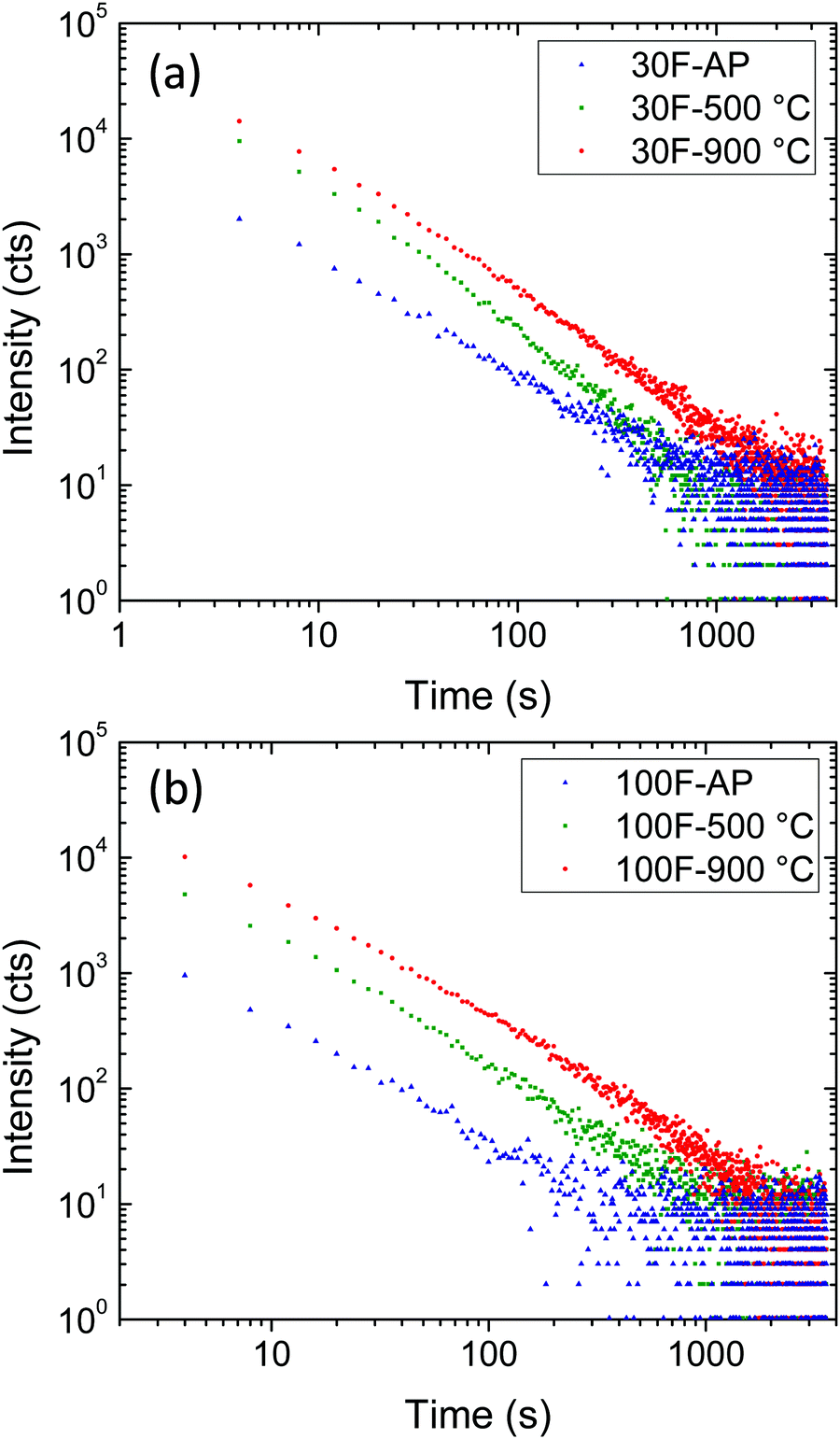 | ||
| Fig. 9 Persistent luminescence decay curves of 30F (a) and 100F (b) ZnGa2O4:Cr3+ thin films as-prepared (AP) and after calcination at 500 °C and 900 °C for 12 h recorded after 10 min excitation at 260 nm. | ||
Both 30F and 100F films, at each processing temperature, showed persistent luminescence decay recordable for more than 1000 s and they exhibited similar decay slopes. On the other hand, the persistent luminescence intensities significantly varied from one film to another. Indeed, similar to photoluminescence intensity, the persistent luminescence intensity of both 30F and 100F increased with calcination temperature. Two effects brought by the increase of the calcination temperature can be linked to this observation: (i) the elimination of surface quenchers, such as citrate ions absorbed on the nanoparticle surface, and (ii) the crystallinity improvement, as inferred from photoluminescence measurements, leading to a higher concentration of efficient traps for persistent luminescence at room temperature. As a result, the persistent luminescence can be recorded for longer times with the films annealed at 900 °C.
Although longer persistence has been reported for bulk ZnGa2O4:Cr3+ powders by other authors,33,34 comparison with the persistence measured on our films is meaningless as we are irradiating a very small area of a really thin film (∼300 nm) by focusing a xenon lamp, while in the referenced papers, the authors irradiated a very large area of a powder sample with a UV lamp. In addition, the time duration of the luminescence always depends on the real performance of the applied apparatus, as emphasized by Xu and Tanabe.1
Thermally stimulated luminescence (TSL) is a powerful tool to investigate the depth and distribution of the traps present in persistent luminescence phosphors. The material is first excited using a suitable wavelength at low temperature (254 nm at 14 K and 5 min in our case) to stimulate charge trapping (electrons and holes). The phosphor is then heated at a constant rate (10 K min−1) while the TSL signal is recorded. When the thermal energy is sufficient, the trapped charges are released and give rise to the emission of photons. The maximum temperature of the TSL peaks can be related to the trap depth while the peak width provides information on the trap-depth distribution, which is somehow related to the structural disorder of the material.50Fig. 10 shows the TSL glow curves obtained for the 30F and 100F films. The as-prepared films showed no significant TSL, while TSL signals extending over a broad temperature range were observed for both films annealed at 500 °C and 900 °C, indicating a broad trap distribution arising from multiple defects. The broad temperature range covered by the TSL glow curves around working temperature (i.e. room temperature in our case) for the annealed samples may explain the similar slopes of the persistent decays previously observed (Fig. 9). Interestingly, the TSL glow curves sharpened and shifted towards higher temperature with increasing calcination temperature. Therefore, the shallow traps, that may be related to surface defects, were minimized at high temperature while the deeper traps, that are the signature of antisite defect pairs, were stabilized with the calcination temperature as a result of the crystallinity improvement. This is in perfect agreement with previous studies of the crystallization temperature effect on the persistent luminescence properties of ZnGa2O4:Cr3+ nanoparticles embedded in glass.53 Consequently, the maximum of the TSL glow peak is slightly higher than the working temperature for the 900 °C calcined films and therefore gets closer to the optimum temperature compared to 500 °C annealed films.51 This is in good agreement with the improved persistent luminescence decay obtained for the 900 °C calcined films compared to the 500 °C calcined films.
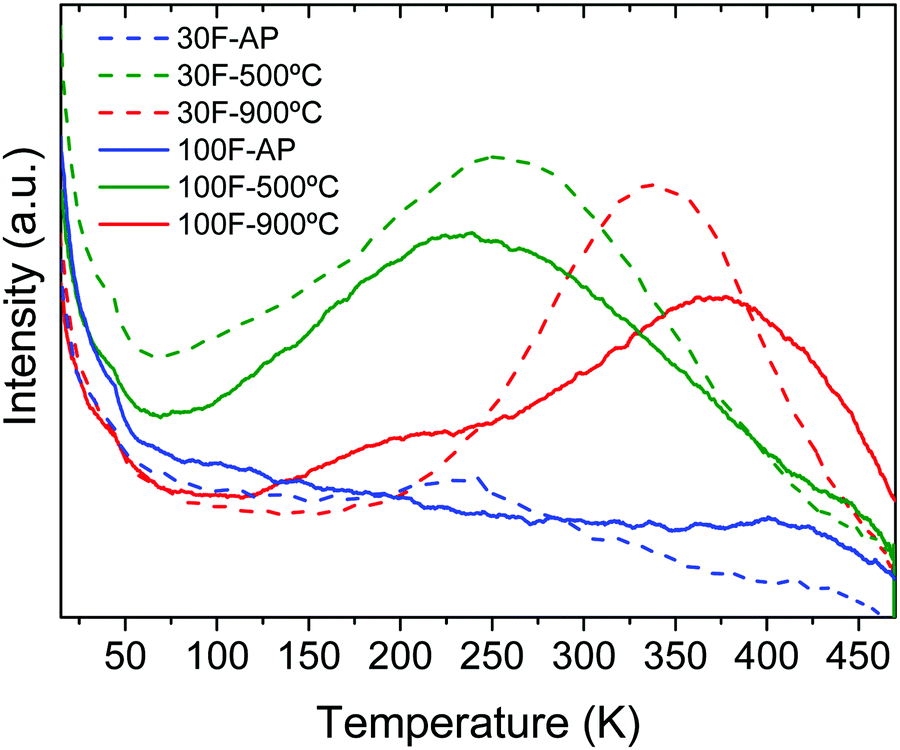 | ||
| Fig. 10 TSL curves recorded after excitation at 254 nm for 5 min and 14 K of 30F and 100F ZnGa2O4:Cr3+ thin films as-prepared (AP) and after calcination at 500 °C and 900 °C for 12 h. | ||
The trap depth energies were estimated from the maxima of the TSL curves (TM) using the Randal and Wilkins formula (Etraps = TM/500)52 and are listed in Table 3. The values obtained for the films annealed at 900 °C are in agreement with those reported in the literature for ZnGa2O4:Cr3+ powders annealed at similar temperatures.53–55 Trap depths in the ∼0.5–1 eV range, as is the case of our films, enable a progressive release of carriers at room temperature, giving rise to persistent luminescence, as observed here.
| 30F | 100F | |||
|---|---|---|---|---|
| T M (K) | E traps (eV) | T M (K) | E traps (eV) | |
| 500 °C | 260 | 0.52 | 250 | 0.50 |
| 900 °C | 340 | 0.68 | 370 | 0.74 |
4. Conclusions
Firstly, a quick synthesis method has been developed which allows the synthesis of uniform, well dispersed ZnGa2O4:Cr3+ spherical particles with tunable diameter in the 30 nm–300 nm range. Second, two different transparent thin films have been fabricated by spin coating using 30 nm and 100 nm ZnGa2O4:Cr3+ nanoparticle suspensions to investigate the effect of particle size on luminescence. Post annealing of the films at high temperature (900 °C) allowed increasing the emission intensity and the afterglow time of the nanophosphor films by around one order of magnitude while preserving their transparency and uniformity. Although the annealed films made from the 100 nm nanoparticles showed higher photoluminescence emission intensity and deeper trap depth, the persistence of luminescence was found to be independent of the size of the precursor nanoparticles. In summary, a global strategy is presented in this work to construct highly uniform, transparent thin films with red to NIR persistent emission, from colloidal suspensions of different size ZnGa2O4:Cr3+ nanoparticles for the first time in the literature. This approach is shown to be a promising route for the fabrication of spinel-based transparent thin films with persistent luminescence as it is an economic and simple technique compared to traditionally used magnetron sputtering methods. The so prepared films may have great potential application in the fields of chemical sensing, information storage, safety signs, and anticounterfeit technology.Author contributions
Investigation: E. A., B. M. and V. C.; supervision: M. O., G. L. and A. I. B.; funding acquisition: M. O., G. L. and A. I. B.; writing – original draft and visualization: A. I. B.; writing – review and editing: M. O. and G. L.Conflicts of interest
There are no conflicts to declare.Acknowledgements
Financial support was provided by the Spanish Ministry of Science, Innovation and Universities (RTI2018-094426-B-I00). This project has also received funding from the European Research Council (ERC) under the European Union's Horizon 2020 Research and Innovation Programme (NANOPHOM, grant agreement no. 715832). E. A. thanks the Spanish Ministry of Science, Innovation and Universities for a FPU grant (Ref. FPU19/00527).References
- J. Xu and S. Tanabe, J. Lumin., 2019, 205, 581–620 CrossRef CAS.
- Y. Li, M. Gecevicius and J. Qiu, Chem. Soc. Rev., 2016, 45, 2090–2136 RSC.
- T. Maldiney, A. Bessière, J. Seguin, E. Teston, S. K. Sharma, B. Viana, A. J. J. Bos, P. Dorenbos, M. Bessodes, D. Gourier, D. Scherman and C. Richard, Nat. Mater., 2014, 13, 418–426 CrossRef CAS PubMed.
- R. Gao and D. Yan, Chem. Commun., 2017, 53, 5408–5411 RSC.
- L. Wang, Y. Lv, T. L. Zhou, R. J. Xie and Y. Zhuang, Adv. Funct. Mater., 2018, 28, 1705769 CrossRef.
- P. F. Smet, D. Poelman and M. P. Hehlen, Opt. Mater. Express, 2012, 2, 452–454 CrossRef.
- K. Jiang, L. Zhang, J. F. Lu, C. X. Xu, C. Z. Cai and H. W. Lin, Angew. Chem., Int. Ed., 2016, 55, 7231–7235 CrossRef CAS PubMed.
- N. Gan, H. Shi, Z. An and W. Huang, Adv. Funct. Mater., 2018, 28, 1802657 CrossRef.
- X. Yang and D. Yan, Adv. Opt. Mater., 2016, 4, 897–905 CrossRef CAS.
- K. Jiang, L. Zhang, J. Lu, C. Xu, C. Cai and H. Lin, Angew. Chem., Int. Ed., 2016, 55, 7231–7235 CrossRef CAS PubMed.
- L. Wang, Z. Shang, M. Shi, P. Cao, B. Yang and J. Zou, RSC Adv., 2020, 10, 11418–11425 RSC.
- H. C. Swart, J. J. Terblans, O. M. Ntwaeaborwa, R. E. Kroon and B. M. Mothudi, Phys. B, 2012, 407, 1664–1667 CrossRef CAS.
- E. Karacaoglu, E. Öztürk, M. Uyaner and M. D. Losego, J. Am. Ceram. Soc., 2020, 103, 3706–3715 CrossRef CAS.
- C. Chen, H. Li, J. Jin, X. Chen, Y. Cheng, Y. Zheng, D. Liu, L. Xu, H. Song and Q. Dai, Adv. Energy Mater., 2017, 7, 1700758 CrossRef.
- P. D. Nsimama, O. M. Ntwaeaborwa and H. C. Swart, J. Lumin., 2011, 131, 119–125 CrossRef CAS.
- A. Bessière, S. Jacquart, K. Priolkar, A. Lecointre, B. Viana and D. Gourier, Opt. Express, 2011, 19, 10131–10137 CrossRef PubMed.
- A. Bessière, S. K. Sharma, N. Basavaraju, K. R. Priolkar, L. Binet, B. Viana, A. J. J. Bos, T. Maldiney, C. Richard, D. Scherman and D. Gourier, Chem. Mater., 2014, 26, 1365–1373 CrossRef.
- A. De Vos, K. Lejaeghere, D. E. P. Vanpoucke, J. J. Joos, P. F. Smet and K. Hemelsoet, Inorg. Chem., 2016, 55, 2402–2412 CrossRef CAS PubMed.
- N. Basavaraju, K. R. Priolkar, D. Gourier, S. K. Sharma, A. Bessiere and B. Viana, Phys. Chem. Chem. Phys., 2015, 17, 1790–1799 RSC.
- M. Allix, S. Chenu, F. Véron, T. Poumeyrol, E. A. Kouadri-Boudjelthia, S. Alahraché, F. Porcher, D. Massiot and F. Fayon, Chem. Mater., 2013, 25, 1600–1606 CrossRef CAS.
- J. Nie, Y. Li, S. Liu, Q. Chen, Q. Xu and J. Qiu, Sci. Rep., 2017, 7, 12392 CrossRef PubMed.
- J. Su, S. Ye, X. Yi, F. Q. Lu, X. B. Yang and Q. Y. Zhang, Opt. Mater. Express, 2017, 7, 734–743 CrossRef CAS.
- Z. Pan, V. Castaing, L. Yan, L. Zhang, C. Zhang, K. Shao, Y. Zheng, C. Duan, J. Liu, C. Richard and B. Viana, J. Phys. Chem. C, 2020, 124, 8347–8358 CrossRef CAS.
- W. Zhang, J. Zhang, Y. Li, Z. Chen and T. Wang, Appl. Surf. Sci., 2010, 256, 4702–4707 CrossRef CAS.
- H. W. Choi, B. J. Hong, S. K. Lee, K. H. Kim and Y. S. Park, J. Lumin., 2007, 126, 359–364 CrossRef CAS.
- O. M. Bordun, V. G. Bihday and I. Y. Kukharskyy, J. Appl. Spectrosc., 2014, 81, 43–48 CrossRef CAS.
- Q. Shi, C. Wang, D. Zhang, S. Li, L. Zhang, W. Wang and J. Zhang, Thin Solid Films, 2012, 520, 6845–6849 CrossRef CAS.
- C. S. Kamal, S. Boddu, B. Vishwanadh, K. R. Rao, V. Sudarsan and R. K. Vatsa, J. Lumin., 2017, 188, 429–435 CrossRef.
- S. Chenu, E. Véron, C. Genevois, A. Garcia, G. Matzen and M. Allix, J. Mater. Chem. C, 2014, 2, 10002–10010 RSC.
- V. Castaing, A. D. Sontakke, J. Xu, A. J. Fernández-Carrión, C. Genevois, S. Tanabe, M. Allix and B. Viana, Phys. Chem. Chem. Phys., 2019, 21, 19458 RSC.
- D. Geng, G. Lozano and H. Miguez, ACS Appl. Mater. Interfaces, 2019, 11, 4219–4225 CrossRef CAS PubMed.
- Z. Li, Y. Zhang, X. Wu, L. Huang, D. Li, W. Fan and G. Han, J. Am. Chem. Soc., 2015, 137, 5304–5307 CrossRef CAS PubMed.
- T. Ai, W. Shang, H. Yan, C. Zeng, K. Wang, Y. Gao, T. Guan, C. Fang and J. Tian, Biomaterials, 2018, 167, 216–225 CrossRef CAS PubMed.
- Y. Wang, C. X. Yangn and X. P. Yan, Nanoscale, 2017, 9, 9049–9055 RSC.
- H. Liu, F. Ren, H. Zhang, Y. Han, H. Qin, J. Zeng, Y. Wang, Q. Sun, Z. Li and M. Gao, J. Mater. Chem. B, 2018, 6, 1508–1518 RSC.
- E. Teston, S. Richard, T. Maldiney, N. Liavre, G. Y. Wang, L. Motte, C. Richard and Y. Lalatonne, Chem. – Eur. J., 2015, 21, 7350–7354 CrossRef CAS PubMed.
- M. Sun, D. Li, W. Zhang, Z. Chen, H. Huang, W. Li, Y. He and X. Fu, J. Solid State Chem., 2012, 190, 135–142 CrossRef CAS.
- D. Geng, G. Lozano, M. E. Calvo, N. O. Núñez, A. I. Becerro, M. Ocaña and H. Míguez, Adv. Opt. Mater., 2017, 5, 1700099 CrossRef.
- A. Zelcer and G. J. A. A. Soler-Illia, J. Mater. Chem. C, 2013, 1, 1359–1367 RSC.
- V. LaMer and R. Dinegar, J. Am. Chem. Soc., 1950, 72, 4847–4854 CrossRef CAS.
- R. Díaz-Torres and S. Alvar, Dalton Trans., 2011, 40, 10742–10750 RSC.
- C. Gabriel, C. P. Raptopoulou, A. Terzis, V. Tangoulis, C. Mateescu and A. Salifoglou, Inorg. Chem., 2007, 46, 2998–3009 CrossRef CAS PubMed.
- S. Capone, A. Robertis, C. Stefano and S. Sammartano, Talanta, 1986, 33, 763–767 CrossRef CAS PubMed.
- M. Matzapetakis, M. Kourgiantakis, M. Dakanali, A. Salifoglou, C. P. Raptopoulou, A. Terzis, A. Lakatos, T. Kiss, I. Banyai, L. Iordanidis and T. Mavromoustakos, Inorg. Chem., 2001, 40, 1734–1744 CrossRef CAS PubMed.
- V. LaMer and R. Dinegar, J. Am. Chem. Soc., 1950, 72, 4847–4854 CrossRef CAS.
- D. Chen and Y. Wang, Nanoscale, 2013, 5, 4621–4637 RSC.
- A. I. Becerro and M. Ocaña, RSC Adv., 2015, 5, 34517–34524 RSC.
- P. M. Aneesh, K. M. Krishna and M. K. Jayaraj, J. Electrochem. Soc., 2009, 156, 33–36 CrossRef.
- N. O. Nuñez, S. Rivera, D. Alcantara, J. M. de la Fuente, J. Garcia-Sevillano and M. Ocaña, Dalton Trans., 2013, 42, 10725–10734 RSC.
- M. Martini and F. Meinardi, Riv. Nuovo Cimento, 1997, 20, 1–71 CrossRef CAS.
- J. Du, O. Q. De Clerq and D. Poelman, Sci. Rep., 2019, 9, 10517 CrossRef PubMed.
- J. T. Randall and M. H. F. Wilkins, Proc. R. Soc. London, Ser. A, 1945, 184, 365–389 CAS.
- V. Castaing, A. D. Sontakke, A. J. Fernandez-Carrion, N. Touati, L. Binet, M. Allix, D. Gourier and B. Viana, Eur. J. Inorg. Chem., 2017, 5114–5120 CrossRef CAS.
- S. K. Sharma, D. Gourier, E. Teston, D. Scherman, C. Richard and B. Viana, Opt. Mater., 2017, 63, 51–58 CrossRef CAS.
- L. Song, P. P. Li, W. Yang, X. Hui Lin, H. Liang, X. F. Chen, G. Liu, J. Li and H. H. Yang, Adv. Funct. Mater., 2018, 28, 1707496 CrossRef.
Footnote |
| † Electronic supplementary information (ESI) available: TEM images of nanoparticles of all members of the series AZG-x and NZG-x, TEM micrographs of precipitates obtained in the absence of citrate, histograms showing size distributions of particles in Fig. 2 of the manuscript, FTIR spectra of NZG-4 and AZG-4 particles. See DOI: 10.1039/d1tc00258a |
| This journal is © The Royal Society of Chemistry 2021 |