
 Open Access Article
 This Open Access Article is licensed under a
 Creative Commons Attribution 3.0 Unported Licence
Electronic and crystal structure of bi-intercalated titanium diselenide CuxNiyTiSe2†
E. G.
Shkvarina
 a,
A. I.
Merentsov
a,
M. S.
Postnikov
a,
A. S.
Shkvarin
*a,
S. V.
Pryanichnikov
b,
I.
Píš
cd,
S.
Nappini
d,
F.
Bondino
d and
A. N.
Titov
a
a,
A. I.
Merentsov
a,
M. S.
Postnikov
a,
A. S.
Shkvarin
*a,
S. V.
Pryanichnikov
b,
I.
Píš
cd,
S.
Nappini
d,
F.
Bondino
d and
A. N.
Titov
a
aInstitute of Metal Physics, Russian Academy of Sciences-Ural Division, 620990 Yekaterinburg, Russia. E-mail: shkvarin@imp.uran.ru
bInstitute of Metallurgy, Ural Branch of Russian Academy of Sciences, 620016, Yekaterinburg, Russia
cElettra – Sincrotrone Trieste S.C.p.A., S.S. 14 km 163.5, 34149 Basovizza, Trieste, Italy
dIOM-CNR, Laboratorio TASC, S.S. 14-km 163.5, 34149 Basovizza, Trieste, Italy
First published on 7th January 2021
Abstract
A comprehensive study of the crystal and electronic structure of TiSe2 intercalated with two 3d metals, Cu and Ni, is presented. It is found that the intercalation of Cu into NixTiSe2 at room temperature leads to the displacement of the Ni atoms from the octahedral to tetrahedral sites with respect to the Se sublattice. This effect is explained by the charge transfer from Cu to the TiSe2-derived conduction band, which makes the chemical bond of Ni with the lattice more stable. This is because the hybridization between Ni 3d and Se 4p, 4s states is stronger than that between Ni 3d and Ti 3d in mono-intercalated NixTiSe2. Therefore, it is possible to control the type of the coordination of the intercalated transition metal atom by changing the concentration of doped electrons.
Introduction
Titanium dichalcogenides TiCh2 (Ch = S, Se, Te) have been studied for a long time.1–6 The intercalation of 3d transition metals into TiCh2 alters significantly the physical properties and electronic structure of these materials.7–10 To date, the effect of intercalation on the electronic structure of layered transition metal dichalcogenides is well understood. However, there is little research on the formation of materials intercalated by several different metals simultaneously. A strong magnetic and, possibly, chemical interaction between intercalated Co and Fe in TiS2 was reported in ref. 11. It has been shown that the intercalation of 0.5 mol% Fe into Co0.25TiS2 changes the character of the magnetic ordering from ferromagnetic (or ferrimagnetic) to antiferromagnetic. Such a small concentration means that the change of the magnetic ordering is due to the interaction between the Fe and Co atoms via the host lattice.On the other hand, an influence of co-intercalation in (Cr,Ni)1/3TaS2 on the physical properties of the material has not been observed.12 This difference may be the result of the different electronic structure of the TiS2 and TaS2 host lattices. Indeed, the electronic configuration of Ti in TiCh2, Ch = S, Se, Te, can be described as d0, while Ta in TaCh2 has the d1 configuration. This results in the location below the Fermi level of the M states in MxTaCh2 and directly at the Fermi level in MxTiCh2. Since it is the states at the Fermi level that are predominantly responsible for the character of the chemical bond, the co-intercalation effect in TiCh2 should be visible more clearly. Little is known about CuxFeyTiSe2,13,14 although the crystal structure and thermodynamic stability in a wide temperature range were studied for this system. It has been shown that the subsystems of Fe and Cu are independent. CuxM0.25TiSe2 (M = Mn, Co, and Ni) co-intercalated compounds were previously investigated by our group.15 However, the research was focused on the lattice parameters and thermodynamic stability only.
It should be noted that the synthesis of all the above mentioned co-intercalated materials was performed at high temperature. This provides the equilibrium for both the sublattices of intercalated metals and the whole crystal lattice. However, the properties of the co-intercalated TiCh2 are likely influenced by the charge transfer, mutual influence of the intercalated metals, their interaction with the host lattice and magnetic interaction. In this study, we focus on Ni and Cu co-intercalation in TiSe2; the possibility of co-intercalation of these metals was reported in ref. 15. Since Cu can be intercalated into TiSe2 at room temperature,16 this provides minimal distortion of the host lattice and the Ni sublattice, but the possibility of charge transfer is preserved. In addition, both Cu in CuxTiSe2 and Ni in NixTiSe2 intercalation compounds occupy the same positions in the van der Waals gap, which are octahedrally coordinated by chalcogen. Therefore, a competition for the occupation of these positions can be expected.
The crystal structure of the TiSe2-based intercalation compound is shown in Fig. 1. Two types of positions in the TiSe2 interlayer space are available for intercalated metals with respect to the Se sublattice: octahedral (shown in gray) and tetrahedral (shown in blue) sites. In all TiSe2-based compounds intercalated by noble and transition metals, intercalated atoms are located in octahedral sites.
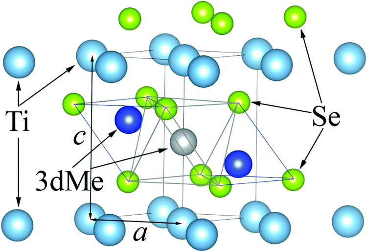 | ||
| Fig. 1 Fragment of MxTiSe2 crystal structure. The tetrahedral sites are shown as two blue spheres and the octahedral site is shown as a gray sphere. | ||
This study is focused on the synthesis and systematic study of the crystal and electronic structures of the co-intercalated CuxNiyTiSe2 compound to clarify the mutual influence of the intercalated metals.
Experiment
The polycrystalline phase of CuxNiyTiSe2 was synthesized by Ni intercalation into TiSe2 followed by Cu intercalation into NiyTiSe2. The synthesis procedures for TiSe2 as well as for Ni intercalation into TiSe2 are described in detail elsewhere.15 Cu intercalation was performed at room temperature by the method described in ref. 16. The CuxNi0.1TiSe2 and CuxNi0.25TiSe2 systems (see Cu concentrations x in Tables 1–3) were successfully synthesized. An increase in the Ni concentration to 50 mol% led to a crumbling of the samples into powder. The contact area between grains became smaller and, consequently, the homogeneous state was not achieved. The only exceptions were the Cu0.1Ni0.5TiSe2 and Cu0.5Ni0.5TiSe2 compounds.| x | a, Å | c, Å | Z Se | Frac. Ni (0 0 1/2) | Frac. Ni (1/3 2/3 z) | Z Ni (1/3 2/3 z) | Frac. Cu (0 0 1/2) | Frac. Cu (1/3 2/3 z) | Z Cu | R F 2, % | χ 2 |
|---|---|---|---|---|---|---|---|---|---|---|---|
| 0.05 (0.011) | 3.540(1) | 5.960(1) | 0.2613(2) | 0.1 | 0 | — | 0.011 | 0 | — | 6.36 | 2.515 |
| 0.1 (0.069) | 3.541(1) | 5.961(1) | 0.2605(2) | 0.047(4) | 0.027(2) | 0.47(1) | 0.069 | 0 | — | ||
| 0.15 (0.108) | 3.541(1) | 5.961(2) | 0.2596(2) | 0.009(1) | 0.045(2) | 0.456(6) | 0.108 | 0 | — | 3.01 | 2.528 |
| 0.2 (0.128) | 3.541(1) | 5.961(1) | 0.2598(2) | 0.003(4) | 0.048(2) | 0.468(6) | 0.122(3) | 0.003(1) | 0.64(6) | 4.34 | 2.815 |
| 0.25 (0.184) | 3.540(1) | 5.961(1) | 0.2587(2) | 0 | 0.05 | 0.430(5) | 0.127(4) | 0.028(2) | 0.496(9) | 2.72 | 2.420 |
| 0.3 (0.260) | 3.542(1) | 5.962(1) | 0.2558(2) | 0 | 0.05 | 0.435(5) | 0.150(3) | 0.055(2) | 0.613(3) | 4.40 | 2.834 |
| 0.35 (0.270) | 3.543(1) | 5.962(1) | 0.2558(2) | 0 | 0.05 | 0.399(5) | 0.162(3) | 0.054(2) | 0.623(3) | 5.70 | |
| 0.4 (0.307) | 3.543(1) | 5.962(1) | 0.2530(2) | 0 | 0.05 | 0.367(6) | 0.163(3) | 0.072(2) | 0.652(3) | 8.57 | 2.817 |
| 0.45 (0.341) | 3.542(1) | 5.961(1) | 0.2522(3) | 0 | 0.05 | 0.420(6) | 0.185(3) | 0.078(2) | 0.654(3) | 7.99 | 3.476 |
| 0.5 (0.303) | 3.540(1) | 5.963(1) | 0.2556(2) | 0 | 0.05 | 0.402(6) | 0.169(4) | 0.067(2) | 0.630(3) | 6.15 | 3.035 |
| x | a, Å | c, Å | Z Se | Frac. Ni (0 0 1/2) | Frac. Ni (1/3 2/3 z) | Z Ni (1/3 2/3 z) | Frac. Cu (0 0 1/2) | Frac. Cu (1/3 2/3 z) | Z Cu | R F 2, % | χ 2 |
|---|---|---|---|---|---|---|---|---|---|---|---|
| 0.05 (0.05) | 3.548(1) | 5.922(1) | 0.2601(2) | 0.210(4) | 0.020(2) | 0.47(1) | 0.05 | 0 | — | 3.98 | 2.889 |
| 0.1 (0.1) | 3.548(1) | 5.922(1) | 0.2592(2) | 0.152(4) | 0.050(2) | 0.437(5) | 0.1 | 0 | — | 4.01 | 2.434 |
| 0.2 (0.173) | 3.549(1) | 5.923(1) | 0.2592(2) | 0.085(4) | 0.083(2) | 0.442(3) | 0.159(3) | 0.007(2) | 0.62(2) | 3.84 | |
| 0.3 (0.258) | 3.549(1) | 5.922(1) | 0.2574(2) | 0.119(4) | 0.065(2) | 0.453(4) | 0.166(3) | 0.046(2) | 0.637(4) | 5.62 | 2.768 |
| 0.35 (0.273) | 3.549(1) | 5.922(1) | 0.2562(3) | 0.072(4) | 0.089(2) | 0.435(3) | 0.181(4) | 0.046(2) | 0.658(5) | 5.45 | 3.045 |
| 0.4 (0.365) | 3.549(1) | 5.923(1) | 0.2519(2) | 0.045(4) | 0.103(2) | 0.396(2) | 0.245(3) | 0.060(2) | 0.639(3) | 7.07 | 3.327 |
| 0.45 (0.399) | 3.549(1) | 5.921(1) | 0.2513(2) | 0 | 0.125 | 0.361(3) | 0.317(4) | 0.041(2) | 0.636(4) | 5.54 | 2.600 |
| 0.5 (0.440) | 3.549(1) | 5.923(1) | 0.2440(2) | 0 | 0.125 | 0.405(2) | 0.365(4) | 0.038(2) | 0.627(5) | 7.45 | 3.507 |
| x | a, Å | c, Å | Z Se | Frac. Ni (0 0 1/2) | Frac. Ni (1/3 2/3 z) | Z Ni (1/3 2/3 z) | Frac. Cu (0 0 1/2) | Frac. Cu (1/3 2/3 z) | Z Cu | R F 2, % | χ 2 |
|---|---|---|---|---|---|---|---|---|---|---|---|
| 0.1 (0.1) | 3.566(1) | 5.928(1) | 0.2600(2) | 0.377(4) | 0.061(2) | 0.429(3) | 0.1 | 0 | — | 4.47 | 2.587 |
| 0.5 (0.5) | 3.566(1) | 5.929(1) | 0.2438(2) | 0.151(5) | 0.175(3) | 0.471(1) | 0.5 | 0 | — | 6.55 | 2.379 |
The homogeneity of the samples was checked by X-ray diffraction analysis. Crystal structure and phase composition were determined using X-ray powder diffraction on a Shimadzu XRD 7000 Maxima diffractometer (Cu Kα1 radiation, graphite monochromator, 2Θ = 12–92, ΔΘ = 0.02, exposure time 1.2 s). The diffraction patterns contained only peaks of the main phase and those of metallic copper (which is not surprising, because the synthesis was carried out at room temperature). The crystal structure refinement was performed using GSAS (General Structure Analysis System) software.17 The chemical compositions of the obtained intercalation compounds are summarized in Tables 1–3.
The single crystals for the soft X-ray spectroscopy measurements were grown from the powdered CuxNiyTiSe2 materials using the gas transport reaction technique in evacuated quartz ampoules with I2 as the gas carrier.18 The single crystals had a shape of thin plates approximately 2–3 mm large and 0.05 mm thick. Two crystals with the composition of Cu0.13Ni0.43TiSe2 and Cu0.2Ni0.25TiSe2 were grown for this work. In addition to the co-intercalated crystals, mono-intercalated NixTiSe2 (x = 0.14, 0.46) and CuxTiSe2 (x = 0.09, 0.33) single crystals were investigated too. Details of their synthesis have been reported elsewhere.19,20
The synchrotron radiation X-ray photoelectron (XPS), X-ray absorption (XAS) and resonant X-ray photoelectron (ResPES) spectra for Ni0.14TiSe2, Cu0.13Ni0.43TiSe2 and Cu0.2Ni0.25TiSe2 were obtained on the CNR IOM BACH beamline21 at the Elettra synchrotron facility (Trieste, Italy). Linearly-polarized X-rays with a polarization vector 60° off the surface plane were used. All the samples were cleaved in situ at room temperature in a vacuum chamber with a base pressure lower than 1 × 10⁻⁹ Torr. The purity of the surface was confirmed by the absence of oxygen and carbon peaks in the XPS survey spectra. XPS spectra were acquired using a VG-Scienta R3000 hemispherical analyzer at an angle of 60° with respect to the X-ray incidence beam. The Ti 2p, Se 3d, Ni 2p and Cu 2p core levels were measured at normal emission angle using 1114 eV excitation energy. The total energy resolution for the core level and valence band spectra was 0.4 eV. The binding energies were calibrated with respect to the Au 4f7/2 (EB = 84.0 eV) signal from a gold reference sample. ResPES spectra were acquired by measuring sets of valence band spectra at photon energies corresponding to the resonances at the Ti L3 and Ni L3 edges. Ni and Ti L3,2 XAS spectra were acquired in total electron yield mode. The photon energy resolution was set to 0.06 eV at Ti L-edge and 0.2 eV at Cu and Ni L-edge, respectively. The photon energy scale was calibrated with an accuracy of 0.1 eV using Au 4f XPS spectra measured with the fundamental and second harmonic of the monochromator. The uncertainty in Ni L-edge calibration is 0.2–0.3 eV.
The XPS and XAS spectra for CuxTiSe2 (x = 0.09, 0.33) were obtained on the Russian–German beamline at the BESSY II synchrotron (Berlin, Germany). The Ti 2p, Se 3d and Cu 2p core levels were measured at normal emission angle at 800 eV excitation energy. The total resolution was approximately 0.2 eV. The binding energies were calibrated with respect to the Pt 4f7/2 (EB = 71.2 eV) signal from a platinum reference sample. All measurements were performed at room temperature.
The XPS and XAS spectra for Ni0.46TiSe2 sample were obtained on the CiPo beamline at the Elettra synchrotron facility. All measurements were performed at room temperature.
The fitting procedure for the XPS spectra was performed using KolXPD software.22
Results
Crystal structure
Following the approach introduced in ref. 15 the crystal structure of CuxNiyTiSe2 was refined in the space group P![[3 with combining macron]](https://www.rsc.org/images/entities/char_0033_0304.gif) m1 (No. 164), atomic positions Ti(1a) (0 0 0), Se(2d) (1/3 2/3 z), Cu1(1b) (0 0 1/2) (octahedral sites), Cu2(2d) (1/3 2/3 z) (tetrahedral sites), Ni1(1b) (0 0 1/2) (octahedral sites), Ni2(2d) (1/3 2/3 z) (tetrahedral sites).23 Site occupancy fractions (SOF) for Ni (1b) and Ni (2d) were constrained by total Ni concentration, considering the multiplicity of the positions. The same constraint was used for SOFs for Cu (1b) and Cu (2d). The background was approximated by Chebyshev polynomials with 16 coefficients.
m1 (No. 164), atomic positions Ti(1a) (0 0 0), Se(2d) (1/3 2/3 z), Cu1(1b) (0 0 1/2) (octahedral sites), Cu2(2d) (1/3 2/3 z) (tetrahedral sites), Ni1(1b) (0 0 1/2) (octahedral sites), Ni2(2d) (1/3 2/3 z) (tetrahedral sites).23 Site occupancy fractions (SOF) for Ni (1b) and Ni (2d) were constrained by total Ni concentration, considering the multiplicity of the positions. The same constraint was used for SOFs for Cu (1b) and Cu (2d). The background was approximated by Chebyshev polynomials with 16 coefficients.
Some X-ray diffraction patterns contained peaks from metallic copper besides the peaks from the main phase. To take this into account, the metallic copper was included into the crystal structure refinement. The fraction of this phase, determined from the refinement, was used to define real Cu content in the intercalation phase (these values are given in brackets in x columns, Tables 1–3). After that, this Cu content in the intercalation phase was fixed and distributed over the 1b and 2d Cu sites. Therefore, when Cu occupied only one of these sites, the corresponding SOF was taken from the weight fraction for the metallic Cu phase and the error bars for the Cu 1b SOF in these cases are not given. The lattice parameters a and c change only slightly when Cu is intercalated into NiyTiSe2 (see Fig. 2 and Tables 1–3). The changes induced by Cu intercalation into NiyTiSe2 are 2 orders of magnitude weaker than that determined by the same amount of Ni.
 | ||
| Fig. 2 Lattice parameters (a – panel a; c – panel b) for CuxNiyTiSe2 obtained from X-ray powder diffraction. | ||
Fig. 3 shows the distribution of the Cu and Ni atoms over the octahedral (1b) and tetrahedral (2d) sites in the interlayer space for CuxNi0.1TiSe2 (panel a) and CuxNi0.25TiSe2 (panel b). Since the lattice parameters change slightly, it is expected that the main changes in the crystal structure will be associated with a change in the type of crystallographic sites occupied by the intercalated atoms.
 | ||
| Fig. 3 Occupation of the octahedral and tetrahedral sites (1b – octahedral sites, 2d – tetrahedral sites) in the interlayer space by the Ni and Cu atoms for CuxNiyTiSe2 (y = 0.1 – panel a, y = 0.25 – panel b). | ||
In both CuxNi0.25TiSe2 and CuxNi0.1TiSe2, the Cu intercalation leads to the displacement of the Ni atoms from the octahedral to tetrahedral sites. However, for CuxNi0.1TiSe2 compounds in the Cu concentration range of 0 < x < 0.013 Cu intercalation does not change the Ni coordination (see. Fig. 3, panel a). Therefore, it can be assumed that for CuxNi0.1TiSe2 the interaction between Ni and Cu atoms is negligible in the Cu concentration range of 0 < x < 0.013. For Cu concentrations of 0.013 < x < 0.12 in CuxNi0.1TiSe2 and 0 < x < 0.17 in CuxNi0.25TiSe2, almost all Cu atoms occupy octahedral sites and each Cu atom displaces one Ni atom from the octahedral to tetrahedral site (Fig. 3, panel b).
The diffraction pattern for Ni0.5TiSe2 contains extra peaks indicating the monoclinic I2/m ordering, as it has been observed previously.24 However, even 10 mol% Cu in Cu0.1Ni0.5TiSe2 turns the crystal structure to the trigonal Pm1 one (see ESI†). Obviously, the disordering of the intercalated atoms is caused by the displacement of the Ni atoms in the tetrahedral sites, while monoclinic ordering requires the occupation of just the octahedral sites.
The Cu intercalation leads to a linear increase in the total occupation of the tetrahedral sites with both Cu and Ni atoms (Fig. 4). At the Cu0.33Ni0.25TiSe2 composition, this value reaches saturation and corresponds to the total occupation of the tetrahedral sites, which is equal to 0.33 (considering the multiplicity 2 × 0.165). This means that one-third of the unit cells contains one intercalated atom in the tetrahedral site. In its turn, this corresponds to the maximum occupation of the tetrahedral sites by both Cu and Ni atoms. Moreover, in the Cu concentration range of 0.05 ≤ x ≤ 0.15 in CuxNi0.25TiSe2 the tetrahedral sites are initially occupied by the Ni atoms only but starting from x = 0.25 the Cu atoms begin to occupy the tetrahedral sites too. In the Cu concentration range of 0.25 ≤ x ≤ 0.45 Cu SOF for the tetrahedral sites does not change significantly, but the Ni atoms are gradually and at x = 0.45 completely displaced to the tetrahedral sites (Fig. 4, panel b).
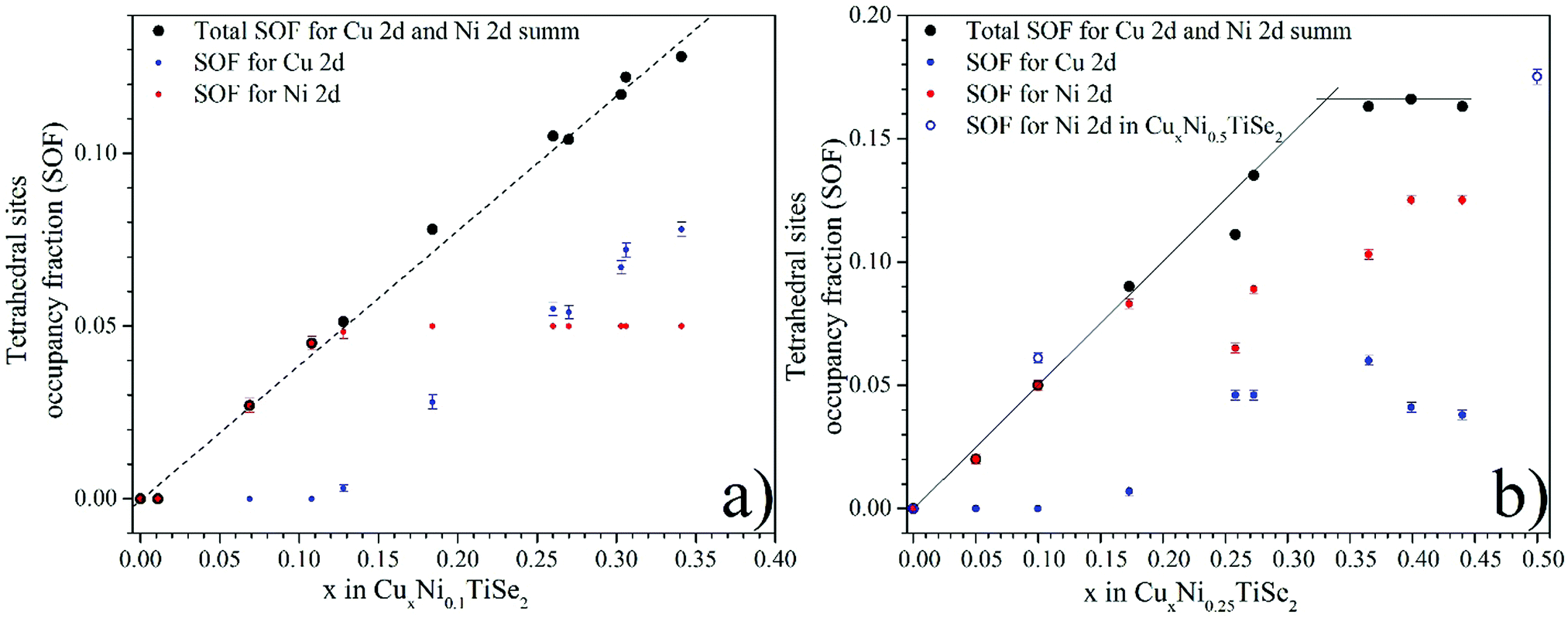 | ||
| Fig. 4 Occupation of the tetrahedral (2d) sites in the interlayer space by the Ni and Cu atoms for CuxNiyTiSe2 (y = 0.1 – panel a, y = 0.25 – panel b). | ||
For the CuxNi0.1TiSe2 system, the total occupation of the tetrahedral sites also increases, but the saturation is not achieved, because the total concentration of the intercalated atoms (Cu + Ni) is less than the saturation value of x + y = 0.33 (see Fig. 4, panel a). But in this case the tetrahedral sites are initially occupied only by the Ni atoms until their complete displacement by the Cu atoms. At x > 0.13 the Cu atoms begin to occupy the tetrahedral sites too. The data for the Cu0.5Ni0.5TiSe2 sample confirms this conclusion: the tetrahedral sites, in this case, are occupied by Ni up to the concentration of y = 0.35, see Table 3 and Fig. 4, panel b.
The total occupation of the octahedral sites (Fig. 5) with the increase in Cu concentration in both CuxNi0.1TiSe2 and CuxNi0.25TiSe2 systems remains constant and approximately equals to the occupation of the octahedral sites by the Ni atoms in Ni0.1TiSe2 and Ni0.25TiSe2. This is probably due to the minimization of the energy of elastic deformation, because the co-intercalation affects the lattice parameters only minimally.
 | ||
| Fig. 5 Occupation of the octahedral (1b) sites in the interlayer space by Ni and Cu for CuxNiyTiSe2 (y = 0.1 – panel a, y = 0.25 – panel b). | ||
Both Ni and Cu atoms can occupy the tetrahedral sites, therefore one can expect the same position of these atoms in the Se tetrahedron, because the ionic radii of Cu and Ni are nearly the same. However, their different electronic configuration makes them to have different z coordinates in the Se tetrahedron. In both systems (y = 0.1 and y = 0.25), the Cu atoms are located closer to the base of the tetrahedron (the face parallel to the (001) plane) (z ≈ 0.62) and the Ni atoms are closer to the opposite vortex (z ≈ 0.42) (Tables 1–3).
XPS
Core level XPS provides insight into the charge state of the atoms. In addition, XPS can be used as a homogeneity test for the studied samples. The Se 3d spectra (Fig. 6) are specially sensitive to the changes in phase composition and surface quality.20,25 | ||
| Fig. 6 The Se 3d spectra for CuxNiyTiSe2. The Se 3d spectra for mono-intercalated CuxTiSe2 and NiyTiSe2 are shown as well. | ||
Even at low Ni concentration (x = 0.14), a shift towards higher binding energies is observed (see Table 4). According to ref. 19, two Ni concentration ranges can be distinguished in NixTiSe2, in which the Se 3d binding energy slightly changes: low Ni concentrations (at x < 0.25 the Ni atoms can be considered as isolated ones), and high Ni concentrations (above x = 0.25, which corresponds to the percolation threshold of the Ti atoms coordinated by Ni). As it can be seen in Fig. 6 and Table 4, the Cu intercalation into NiyTiSe2 leads to a further shift of the Se 3d line toward the higher binding energies. This is in good agreement with previously obtained data for the CuxTiSe2 system for x < 0.2, where Cu intercalation also did not affect the shift of the Se 3d line.20 Probably, the increase in the Se 3d binding energy is not the result of an electron transfer from Cu to the lattice, but the result of redistribution of the Ni atoms due to the Cu intercalation.
| Sample | Se 3d5/2, eV | Ti 2p3/2, eV | Ni 2p3/2, eV | Ti L3(A), eV | Ti L3(B), eV | VBT, eV | VBR, eV | I T | I R |
|---|---|---|---|---|---|---|---|---|---|
| TiSe2 | 53.2 | 455.63 | n/a | 455.93 | 457.87 | n/a | n/a | n/a | n/a |
| Cu0.33TiSe2 | 52.87 | 455.2 | n/a | 455.97 | 457.94 | n/a | n/a | n/a | n/a |
| Ni0.14TiSe2 | 53.34 | 455.67 | 852.32 | 455.94 | 457.95 | 0.95 | 0.15 | 0.18 (0.11) | 0.06 |
| Ni0.46TiSe2 | 53.71 | 455.7 | 852.38 | 455.42 | 457.48 | 1.219 | 0.4519 | 0.5519 | 0.2419 |
| 454.64 | |||||||||
| Cu0.13Ni0.43TiSe2 | 53.95 | 456.0 | 852.44 | 455.6 | 457.62 | 1.1 | 0.25 | 0.44 (0.46) | 0.18 |
| 454.8 | |||||||||
| Cu0.2Ni0.25TiSe2 | 53.51 | 456.17 | 852.41 | 455.6 | 457.49 | 1.13 | 0.3 | 0.4 (0.56) | 0.15 |
| 53.91 | 454.8 |
The Se 3d line width is sensitive to the distribution of the Ni atoms over the octahedral and tetrahedral sites. Indeed, for Cu0.13Ni0.43TiSe2, which is close to Cu0.1Ni0.5TiSe2, almost all the Ni atoms are in the octahedral sites, and the Se 3d line is just slightly broader than that for Ni0.46TiSe2. In its turn, in Ni0.46TiSe2 all of the Ni atoms occupy only the octahedral sites, whereas in Cu0.2Ni0.25TiSe2 the Ni atoms are nearly equally distributed between the octahedral and tetrahedral sites (see Fig. 3, panel a), and the Se 3d line becomes broad and its double-peak structure cannot be observed. Considering the site occupancy fractions of the octa- and tetrahedral sites (see Table 2, SOF = 0.244 for 1b sites, SOF = 0.173 for 2d sites) we can assume that in Cu0.2Ni0.25TiSe2 the Se 3d states with higher binding (dark green dashed line, Fig. 6) are due to the Se atoms forming the octahedrons, while those with lower binding energies (light green dashed line, Fig. 6) are due to the Se atoms forming the tetrahedrons.
The Ti 2p spectra are shown in Fig. 7. They are similar to those for the NiyTiSe2 system.19 The second (with higher binding energy) Ti state appears due to the presence or absence of intercalated atoms in the second coordination sphere of Ti atoms. This is in a good agreement with the fact that the change in the Cu concentration in CuxTiSe2 did not affect the Ti 2p spectra.20
 | ||
| Fig. 7 The Ti 2p spectra for CuxNiyTiSe2. The Ti 2p spectra for mono-intercalated CuxTiSe2 and NiyTiSe2 are shown as well. | ||
The Cu 2p spectra shown in Fig. 8 (left panel) are almost identical to those for the CuxTiSe2 system20 and correspond to the Cu0 or CuI charge state. This is not surprising since the Cu atoms occupy identical octahedral sites in all of these compounds.
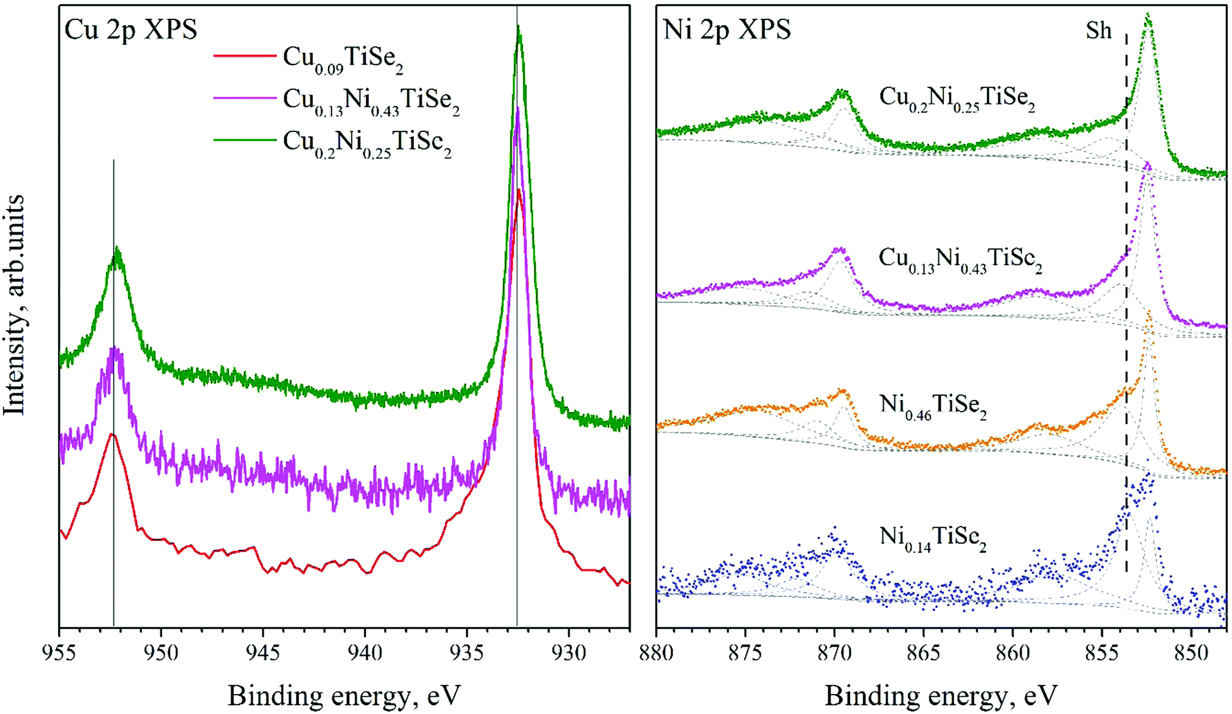 | ||
| Fig. 8 The Cu 2p spectra for CuxNiyTiSe2 and Cu0.09TiSe2 (left panel). The Ni 2p spectra for CuxNiyTiSe2 and NiyTiSe2 (right panel). | ||
The binding energy of the Ni 2p state (Fig. 8, right panel) does not depend on the Ni or Cu concentration (Table 4). However, a change in the shape of the Ni 2p spectrum is observed. With the increase in the Cu concentration, the intensity of a satellite (marked as Sh in Fig. 8) significantly decreases.
XAS
The X-ray absorption spectra provide information regarding the ratio of the ionic and covalent contribution to the chemical bond of the selected atom.26 This characteristic is related to the local arrangement of the selected atoms and their nearest neighbors; therefore, it should be sensitive to the crystal field effects.The Ti L2.3 absorption spectra are shown in Fig. 9, left panel. A change in the Cu concentration does not affect the shape and energy position of Ti L2.3 XAS, as in the case of the Ti 2p core-level spectra. The Ti L2.3 absorption spectra can be divided into two groups: the first group for the compounds with low Ni concentration (x < 0.25), the second one for the compounds with high Ni concentration (x ≥ 0.25). The difference in the Ti coordination in these groups is related to the different influence of the neighboring Se atoms. In Ni0.46TiSe2 the ordering of Ni resulting in the monoclinic structure is observed. This distorts the Se sublattice and, consequently, leads to a change in the coordination of the Ti atoms by the Se ones.24 Another way to distort the Se sublattice is redistribution of the Ni atoms between the octa- and tetrahedral sites caused by the Cu intercalation. This distortion can change the local crystal field around Ti atoms and influence the lineshape of Ti L2.3 XAS.
 | ||
| Fig. 9 Ti L2.3 XAS for CuxNiyTiSe2 (left panel). Cu L2.3 XAS for CuxNiyTiSe2 (right panel). | ||
The Cu L2.3 absorption spectra are shown in Fig. 9, right panel. As one can see, Cu L2.3 XAS for Cu0.13Ni0.43TiSe2 is almost identical to that for Cu0.33TiSe2 without Ni intercalation. As the Cu concentration increases (Cu0.2Ni0.25TiSe2), the lineshape changes; additional bands marked with arrows in Fig. 9 appear. In Cu0.13Ni0.43TiSe2, which is close in chemical composition to Cu0.1Ni0.5TiSe2, all of the Cu atoms occupy the octahedral sites, as in the CuxTiSe2 compounds. Although in Cu0.2Ni0.25TiSe2 the Cu atoms also mostly occupy the octahedral sites, some of them occupy the tetrahedral sites. Therefore, these additional XAS features can be associated with the Cu atoms in the tetrahedral sites.
The Ni L2.3 absorption spectra (Fig. 10) substantially depend on the Cu concentration. Cu intercalation into NiyTiSe2 changes the lineshape. The Ni atoms in Ni0.14TiSe2 occupy the octahedral sites only. In Cu0.13Ni0.43TiSe2 (Cu0.1Ni0.5TiSe2), the Ni atoms occupy mainly the octahedral sites, whereas in Cu0.2Ni0.25TiSe2 they are equally distributed over the octahedral and tetrahedral sites. Two different coordination of the Ni atoms result in a broadening of the Ni L2.3 absorption spectrum for Cu0.2Ni0.25TiSe2 (FWHM = 1.7 eV) as compared to that for Cu0.13Ni0.43TiSe2 (FWHM = 1.5 eV) (see the inset in Fig. 10). Moreover, there is a pronounced difference between the shapes of the Ni L3.2 XAS spectra for Ni0.14TiSe2 and CuxNiyTiSe2. This difference can be related to the different crystal field around Ni atoms in the tetrahedral sites.
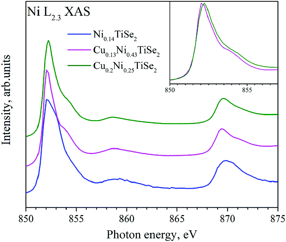 | ||
| Fig. 10 Ni L2.3 XAS for CuxNiyTiSe2. The inset shows Ni L3 XAS for Cu0.13Ni0.43TiSe2 and Cu0.2Ni0.25TiSe2. | ||
Valence band
The photoemission spectra of the valence band (VB) provide insight into the state of the valence electrons that are responsible for the chemical bonds in the material. The use of excitation radiation with a resonant energy close to the 2p–3d transition energy allows for determination of the partial atomic contributions in the density of states in the valence band. The VB spectra for CuxNiyTiSe2 are shown in Fig. 11. | ||
| Fig. 11 The valence band spectra for CuxNiyTiSe2. The excitation energies are as follows: Eexc = 1115 eV for TiSe2; Eexc = 848.4 eV for Ni0.14TiSe2; Eexc = 847.8 eV for Cu0.13Ni0.43TiSe2; Eexc = 800 eV for Cu0.2Ni0.25TiSe2. The peaks typical for TiCh2 are shown with red dots. The T and R peaks appearing at the Cu and Ni intercalation are shown with gray dashed line. | ||
The VB spectra for CuxNiyTiSe2 differ from those for TiSe2 by the presence of T and R peaks near the Fermi level. Both of these peaks are typical for the NixTiSe2 system.19 One can see that the intensity of the T peak increases with Ni concentration. The intensity of the R peak also increases with Ni concentration but does not depend on the Cu concentration (Table 4). However, for all the studied compounds CuxMeCh2 (Me = Ti, Zr; Ch = S, Se, Te) Cu states are not observed near the Fermi level.27,28 To clarify the partial contribution to the states near the Fermi level, the resonant photoemission spectroscopy was used.29–32 The valence band spectra for CuxNiyTiSe2 obtained in the Ti 2p3/2–3d resonant excitation mode are shown in Fig. 12.
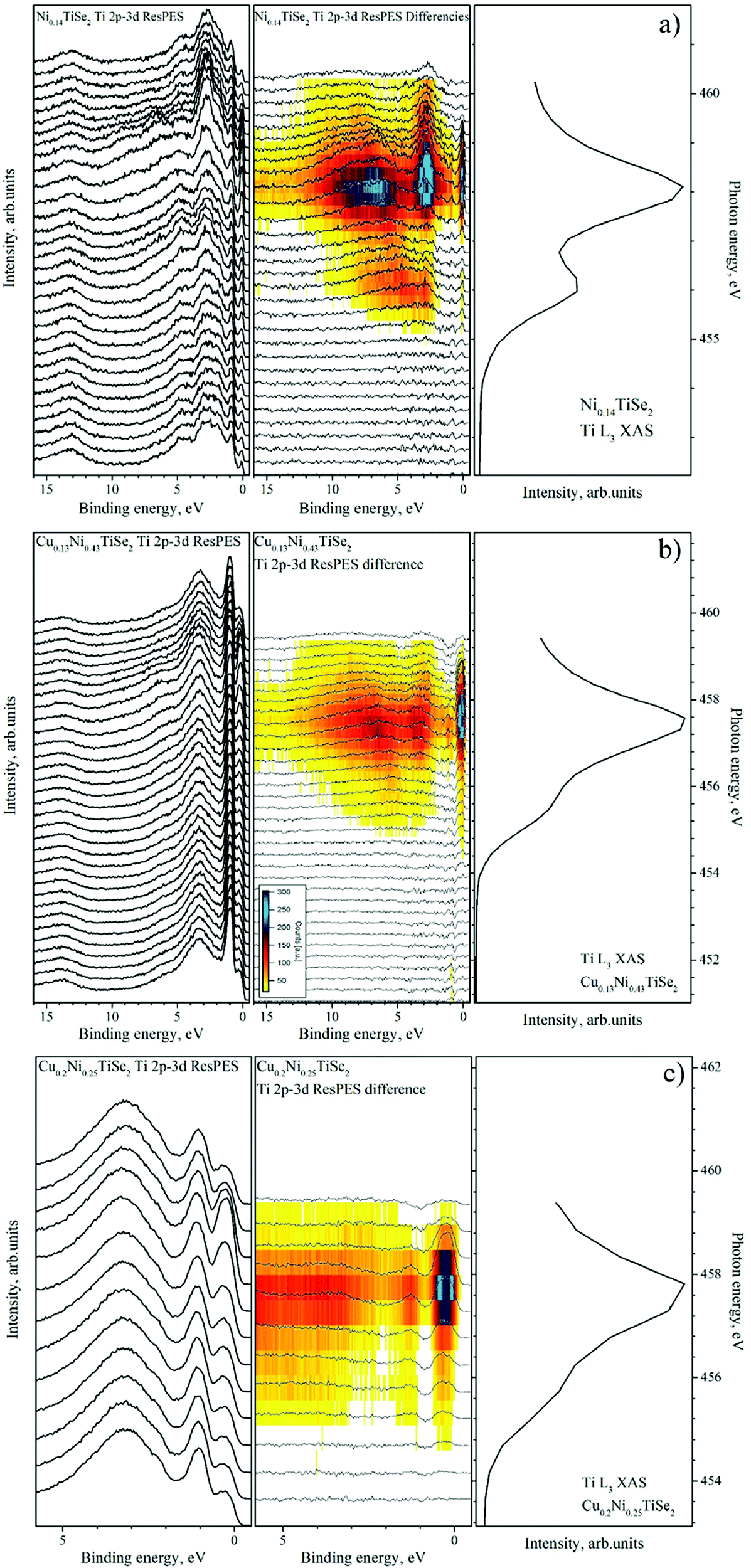 | ||
| Fig. 12 The valence band spectra obtained in the Ti 2p3/2–3d resonant excitation mode for Ni0.14TiSe2 (panel a), Cu0.13Ni0.43TiSe2 (panel b) and Cu0.2Ni0.25TiSe2 (panel c). For all the compounds (from left to right): the VB spectra obtained at different excitation energies; the difference spectra obtained by the subtraction of the off-resonance spectrum from the spectrum at the current excitation energy (as described in ref. 33); the corresponding Ti L3 absorption spectrum. | ||
One can see that the Cu intercalation into NiyTiSe2 leads to an increase in the intensity of the resonant line directly at the Fermi level. This effect can be explained as a result of the filling of the Ti 3d conduction band. We can conclude that the Cu intercalation in both TiSe2 and NiyTiSe2 leads to the charge transfer to the conduction band formed mainly by the Ti 3d states.
To obtain additional information about the states near the Fermi level, constant initial state (CIS) spectra are useful. The CIS experiment is carried out by simultaneously varying the photon energy and the photoelectron kinetic energy, i.e. the measurement is performed at constant ionization (or binding) energy. Ti 2p3/2–3d CIS obtained at Eb = 0.15 eV from the ResPES spectra are shown in Fig. 13.
 | ||
| Fig. 13 Ti 2p3/2–3d CIS at Eb = 0.15 eV for CuxNiyTiSe2 obtained from the ResPES spectra. | ||
One can see that CIS are almost identical to the lineshape of Ti L2.3 XAS for corresponding samples. For Ni0.14TiSe2 both A and B peaks are clearly visible, however for Cu0.13Ni0.43TiSe2 and Cu0.2Ni0.25TiSe2 only the A peak is well resolved. This allows to associate these 0.15 eV-states with Ti 3d states. Different CIS for CuxNiyTiSe2 and NiyTiSe2 indicate that Cu intercalation changes the chemical bond of the Ti atoms. Indeed, it is known that the Ti 3dz2 orbitals hybridize with the nearest neighbors.34 Since the Ti 3dz2 orbital is directed at the octahedral site, it hybridizes with the orbitals of an atom, which is located there. However, the intensity of the resonance peak is nearly the same for all studied compounds (Fig. 14, right panel), but its width substantially increases with Cu intercalation (Fig. 14, left panel). This increase may indicate the appearance of additional hybridized states near the Fermi level.
 | ||
| Fig. 14 The on-maximum VB spectra obtained in the Ti 2p3/2–3d resonant excitation mode (left panel) and those after off-resonance spectra subtraction (right panel) for CuxNiyTiSe2. The data processing is described in detail in ref. 33. | ||
The VB spectra obtained in the Ni 2p–3d resonant excitation mode are shown in Fig. 15. The main contribution is from the RRAS (resonant Raman Auger spectra) peak; however, after the subtraction of the off-resonance spectrum, a small resonance near the Fermi level both for CuxNiyTiSe2 and for Ni0.14TiSe2 can be detected at photon energies slightly beyond the resonant maximum (this peak is marked as R in Fig. 16, right panel).
 | ||
| Fig. 15 The VB spectra obtained in the Ni 2p3/2–3d resonant excitation mode for Ni0.14TiSe2 (panel a), Cu0.13Ni0.43TiSe2 (panel b) and Cu0.2Ni0.25TiSe2 (panel c). For all the compounds (from left to right): the VB spectra obtained at different excitation energies; the difference spectra obtained by the subtraction of the on-resonance spectrum from the spectrum at the current excitation energy (as described in ref. 33); the corresponding Ni L3 absorption spectrum. | ||
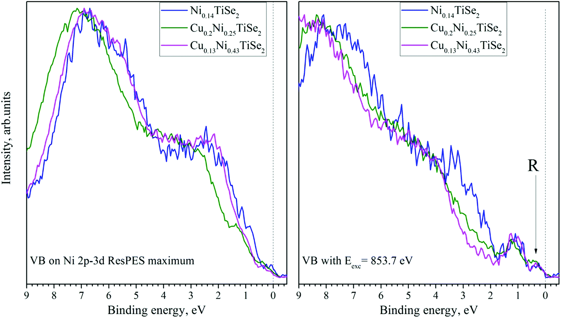 | ||
| Fig. 16 The on-resonance (left panel) and near-resonance (Eexc = 853.7 eV) (right panel) VB spectra obtained in the Ni 2p3/2–3d resonant excitation mode for CuxNiyTiSe2 after additional processing (as described in ref. 33 and 35). | ||
Discussion
The Cu intercalation into NiyTiSe2 led to unintended consequences such as the displacement of the Ni atoms from the octahedral to tetrahedral sites even at room temperature.It would seem that this displacement of the Ni atoms to the tetrahedral sites by the Cu ones is probably caused by a Coulomb repulsion. However, the fact that the repulsion effect is observed even at x < 0.12 (for y = 0.1) and x < 0.17 (for y = 0.25), when the average distances between the intercalated atoms exceeds 18a, indicates, that this interaction occurs involving the host lattice.
The XPS spectra are sensitive to the effective charge of the selected atoms, however no significant changes in the Cu 2p and Ni 2p binding energies with a change in the Cu concentration are observed; the Ni and Cu charge states coincide with those in mono-intercalated compounds. At the same time, there is a sharp decrease in the Ti 2p binding energy and an increase in the Se 3d binding energy in the core-level spectra for CuxNiyTiSe2 as compared to those for NiyTiSe2. These changes may be caused by the redistribution of the Ni atoms over the octahedral and tetrahedral sites. As it was shown in ref. 19, the Ni 3d/Ti 3d hybridized band is formed in NiyTiSe2 below the Fermi level. This band acts as a trap for the conduction electrons; therefore, the Ni doping does not increase the Fermi energy. The displacement of the Ni atoms to the tetrahedral sites makes the Ni 3d/Se 4p hybridization possible instead of the Ti 3d/Ni 3d one. To make the Ni–Se chemical bond stable, this hybridized band should lie below the Fermi level. Consequently, the displacement of the Ni atoms from the octahedral to tetrahedral sites should lead to the “return” of the Ti electrons participating in the Ni 3d/Ti 3d hybridized band and trap the Se electrons participating in the Ni 3d/Se 4p hybridized band. This should decrease the Ti and Se effective charges, as indicate the Se 3d and Ti 2p core-level spectra (Fig. 6 and 7, respectively, Table 4). This effect involves both Ni and Cu. The trend of the total (Ni + Cu) SOF for the tetrahedral sites to the constant value of approximately 1/6 indicates this (see Fig. 4, panel b).
An increase in the Se 3d binding energy should be associated with a decrease in the effective ionic charge of the selenium. Since both Ni and Cu atoms cannot be acceptors, this effect can only be associated with the formation of covalent bonds involving Ni and/or Cu states. These covalent centers could play the role of effective acceptors. As can be seen from Fig. 3 (panel b), such states are formed when Ni atoms occupy tetrahedral sites; this results in the broadening of the Se 3d line for Cu0.2Ni0.25TiSe2 (see Fig. 6 and Table 4).
A joint analysis of the VB spectra obtained in both resonant and non-resonant excitation modes shows that the states forming the T peak (Fig. 11) are not observed upon Ti 2p–3d and Ni 2p–3d resonance excitation, although the intensity of this peak changes noticeably. Based on the results of density of states (DOS) calculations for MxTiCh2 (M = 3d transition metal, Ch = S, Se, Te),19,25,26,28,36 it can be assumed that the band corresponding to the T peak is formed mainly by the Se states hybridized with the Ti and Ni states. The R peak is clearly visible (Fig. 14 and 16) in the VB spectra obtained both in the Ti 2p–3d and Ni 2p–3d resonant excitation modes. This means that both the Ti 3d and Ni 3d states form the band resulting in the peak R. This is only possible when the Ni atoms occupy the octahedral sites. Therefore, the Cu intercalation leading to the displacement of the Ni atoms to the tetrahedral sites, should decrease the intensity of the R peak. However, this displacement is accompanied by the donation of Cu electrons into the Ti 3d state. This increases the intensity of the R peak, which does not decrease, as it should be upon the displacement of the Ni atoms to the tetrahedral sites. The R peak is also observed in the Ni0.14TiSe2 spectra (see Fig. 11, 12, 15 and 16); however, its intensity is low because the Ti 3d states are almost empty. The Cu intercalation injects electrons to the Ti 3d states and, therefore, should increase the intensity of the R peak. We observed previously this peak and a similar effect for the CuxTiSe2 system.20 Thus, the increase in the intensity of the R peak caused by the filling of the Ti 3d states compensates the decrease in the intensity of the R peak caused by the decreased occupation of the octahedral sites by the Ni atoms.
As follows from the analysis of the XPS and XAS spectra for CuxNiyTiSe2, the intercalated Cu atoms donate electrons to the Ti 3d-derived conduction band. This leads to an increase in the Fermi energy; as a result, the Ni 3d/Se 4p hybridized band appears below the Fermi level. This is clearly seen comparing the ResPES spectra for Ni0.14TiSe2 and Cu0.13Ni0.43TiSe2, in which Cu and Ni atoms occupy the same octahedral sites. However, an increase in the Cu concentration up to x = 0.2 in Cu0.2Ni0.13TiSe2 leads both to a displacement of the Ni atoms to the tetrahedral sites and to the disappearance of the filled Ti 3d states directly at the Fermi level. Obviously, this depletion of the conduction band is associated with the absorption of electrons by a new hybridized band. Since in the observed Ni2+ charge state only Ni 3dxz and Ni 3dyz orbitals directed to the Se atoms remain unfilled, the filling of the Ni 3d shell due to the Cu intercalation leads to the amplification of the interaction between the Ni and Se atoms. Probably, it is the Ni 3d/Se 3p states that capture the electrons from the Ti 3d-derived conduction band.
It should be noted that in CuxNiyTiSe2 the Cu atoms occupy both tetrahedral and octahedral sites, whereas in mono-intercalated CuxTiSe2 all of the Cu atoms occupy only the octahedral sites. Unfortunately, we have not succeeded to prepare CuxNiyTiSe2 single-crystal samples with tetrahedrally coordinated copper. In Cu0.13Ni0.43TiSe2 the Cu atoms occupy the octahedral sites only; in Cu0.2Ni0.25TiSe2, the Cu atoms occupy also the tetrahedral sites, but SOF for these sites is much smaller than that for the octahedral sites. We can assume two possible reasons for the redistribution of the Cu atoms in CuxNiyTiSe2 over the tetrahedral and octahedral sites. The first one is a covalent interaction between the Cu and Ni atoms involving the host TiSe2 lattice. This is supported by the trend of the total SOF for the tetrahedral sites to a “specific” value of 1/6 (Fig. 4, panel b). The second one is the perturbation of the Se sublattice by the Ni atoms, which makes the Cu 4p,3d/Se 4p hybridization in CuxNiyTiSe2 more energetically favorable than that in CuxTiSe2.
It should be noted that the redistribution of the Ni atoms over the octahedral and tetrahedral sites provides only small changes in the lattice parameters upon the Cu intercalation. This confirms the previously reported assumption37 that the lattice deformation upon intercalation is associated only with the occupation of the octahedral sites. The observed invariance of the lattice parameters (Fig. 2) can be useful for the application in electrochemical devices.
Conclusions
In this study, the systematic analysis of the crystal and electronic structure of the co-intercalated CuxNiyTiSe2 system has been performed for the first time. It was found that the Cu intercalation into NiyTiSe2 leads to the displacement of the Ni atoms from the octahedral to tetrahedral sites. This displacement can be explained by a change in the electronic structure. Being in an octahedral environment Ni2+ has unfilled dxz and dyz orbitals oriented to the chalcogen atoms. Being in a tetrahedral environment, Ni has 3 orbitals directed to the chalcogen atoms and 2 orbitals parallel to the basal plane. Obviously, the Ni atoms should balance between the occupation of octa- and tetrahedral sites; this means, respectively, the balance between the Ni 3d/Ti 3dz2/Se 3p (one Ni orbital is hybridized with Ti orbitals and two of them are hybridized with Se orbitals) and Ni 3d/Se 3p (three Ni orbitals are hybridized with Se orbitals) hybridization. An increase in the Ti 3d band filling makes the Ni 3d/Se 3p hybridization preferable, probably due to an increase in the Fermi energy and decrease in the energy gain at the Ni 3d/Ti 3d hybridization. Thus, the prediction of the preferred coordination of the intercalated atoms in these compounds should consider the spatial electronic configuration of the d-orbitals of these atoms.The displacement of the Ni atoms from the octahedral to tetrahedral sites should also be observed in the case of the intercalation of NiyTiSe2 by other donor dopants weakly perturbing the crystal structure of the host lattice. For example, alkali metals fit well for this purpose. As a particular advantage, it can be noted that the displacement of the Ni atoms occurs at room temperature. Therefore, we expect this can be easily obtained by the electrochemical intercalation.
Conflicts of interest
There are no conflicts to declare.Acknowledgements
The research was carried out within the state assignment of Minobrnauki of Russia (theme “Electron” No. AAAA-A18-118020190098-5 and theme “Spin” No. AAAA-A18-118020290104-2) and with partial financial support of the RFBR (project 18-32-20141). This work has been done using facilities of the Shared Service Centre “Ural-M”, Institute of Metallurgy of the Ural Branch of the Russian Academy of Sciences. I. P., S. N. and F. B. acknowledge funding from EUROFEL project (RoadMap Esfri). This project has received funding from the EU-H2020 research and innovation program under grant agreement No. 654360 having benefitted from the Access provided by IOM-CNR in Trieste (Italy) within the framework of the NFFA-Europe Transnational Access Activity. We acknowledge the Elettra Sincrotrone Trieste for providing access to its synchrotron radiation facilities and we thank N. Zema for assistance in using beamline CiPo.References
- J. A. Wilson and A. D. Yoffe, Adv. Phys., 1969, 18, 193–335 CrossRef CAS.
- R. M. White and G. Lucovsky, Solid State Commun., 1972, 11, 1369–1373 CrossRef CAS.
- C. M. Fang, R. A. de Groot and C. Haas, Phys. Rev. B: Condens. Matter Mater. Phys., 1997, 56, 4455–4463 CrossRef CAS.
- H. Cercellier, C. Monney, F. Clerc, C. Battaglia, L. Despont, M. G. Garnier, H. Beck, P. Aebi, L. Patthey, H. Berger and L. Forró, Phys. Rev. Lett., 2007, 99, 146403 CrossRef CAS.
- D. J. Campbell, C. Eckberg, P. Y. Zavalij, H.-H. Kung, E. Razzoli, M. Michiardi, C. Jozwiak, A. Bostwick, E. Rotenberg, A. Damascelli and J. Paglione, Phys. Rev. Mater., 2019, 3, 053402 CrossRef CAS.
- C. Lian, S.-J. Zhang, S.-Q. Hu, M.-X. Guan and S. Meng, Nat. Commun., 2020, 11, 43 CrossRef CAS.
- E. Morosan, H. W. Zandbergen, B. S. Dennis, J. W. G. Bos, Y. Onose, T. Klimczuk, A. P. Ramirez, N. P. Ong and R. J. Cava, Nat. Phys., 2006, 2, 544–550 Search PubMed.
- M. Inoue, H. P. Hughes and A. D. Yoffe, Adv. Phys., 1989, 38, 565–604 CrossRef CAS.
- E. Guilmeau, Y. Bréard and A. Maignan, Appl. Phys. Lett., 2011, 99, 052107 CrossRef.
- D. Kraft, U. Weiler, Y. Tomm, A. Thissen, A. Klein and W. Jaegermann, Thin Solid Films, 2003, 431–432, 382–386 CrossRef CAS.
- M. Inoue, M. Koyano, H. Negishi and M. Sasaki, Mol. Cryst. Liq. Cryst. Sci. Technol., Sect. A, 1994, 245, 37–42 CrossRef CAS.
- G. A. Takzei, M. V. Gavrilenko, I. I. Sych, P. Esquinazi and L. M. Kulikov, Phys. Solid State, 1997, 39, 1607–1611 CrossRef.
- V. F. Balakirev and A. A. Titov, Phys. Solid State, 2013, 55, 598–602 CrossRef CAS.
- A. A. Titov, A. N. Titov, O. V. Bushkova and V. A. Tsurin, Phys. Solid State, 2010, 52, 1577–1584 CrossRef CAS.
- A. A. Titov, A. N. Titov, S. G. Titova, S. V. Pryanichnikov and D. S. Chezganov, Phys. Solid State, 2017, 59, 145–150 CrossRef CAS.
- E. G. Shkvarina, A. A. Titov, A. A. Doroschek, A. S. Shkvarin, D. V. Starichenko, J. R. Plaisier, L. Gigli and A. N. Titov, J. Chem. Phys., 2017, 147, 044712 CrossRef CAS.
- A. C. Larson and R. B. Von Dreele, Doc. LAUR, 1994, 86–748 Search PubMed.
- H. P. B. Rimmington, A. A. Balchin and B. K. Tanner, J. Cryst. Growth, 1972, 15, 51–56 CrossRef.
- A. S. Shkvarin, Y. M. Yarmoshenko, A. I. Merentsov, Y. M. Zhukov, A. A. Titov, E. G. Shkvarina and A. N. Titov, Phys. Chem. Chem. Phys., 2017, 19, 4500–4506 RSC.
- A. S. Shkvarin, Y. M. Yarmoshenko, M. V. Yablonskikh, A. I. Merentsov, E. G. Shkvarina, A. A. Titov, Y. M. Zhukov and A. N. Titov, J. Chem. Phys., 2016, 144, 074702 CrossRef CAS.
- M. Zangrando, M. Finazzi, G. Paolucci, G. Comelli, B. Diviacco, R. P. Walker, D. Cocco and F. Parmigiani, Rev. Sci. Instrum., 2001, 72, 1313 CrossRef CAS.
- J. Libra, KolXPD (Revision 1.8.0 build 61), Kolibrik.net, s.r.o., Žd'ár nad Sázavou, Czech Republic, 2017.
- E. Prince, International tables for crystallography, ed. A. J. C. Wilson, Kluwer, 2004, vol. 100 Search PubMed.
- Y. Arnaud, M. Chevreton, A. Ahouandjinou, M. Danot and J. Rouxel, J. Solid State Chem., 1976, 18, 9–15 CrossRef CAS.
- A. S. Shkvarin, Y. M. Yarmoshenko, A. I. Merentsov, I. Píš, F. Bondino, E. G. Shkvarina and A. N. Titov, Inorg. Chem., 2018, 57, 5544–5553 CrossRef CAS.
- A. S. Shkvarin, Y. M. Yarmoshenko, N. A. Skorikov, M. V. Yablonskikh, A. I. Merentsov, E. G. Shkvarina and A. N. Titov, J. Exp. Theor. Phys., 2012, 114, 150–156 CrossRef CAS.
- A. S. Shkvarin, A. I. Merentsov, Y. M. Yarmoshenko, M. S. Postnikov, E. G. Shkvarina, E. V. Mostovshchikova, A. A. Titov, I. Pis, F. Bondino, S. A. Uporov, S. Y. Melchakov and A. N. Titov, J. Mater. Chem. C, 2020, 8, 8290–8304 RSC.
- A. S. Shkvarin, A. I. Merentsov, N. Tsud and A. N. Titov, J. Chem. Phys., 2019, 151, 234701 CrossRef CAS.
- R. Z. Bachrach, Synchrotron Radiation Research: Advances in Surface and Interface Science Techniques, Springer Science & Business Media, 2012, vol. 1 Search PubMed.
- A. Kay, E. Arenholz, S. Mun, F. J. G. de Abajo, C. S. Fadley, R. Denecke, Z. Hussain and M. A. Van Hove, Science, 1998, 281, 679–683 CrossRef CAS.
- J.-E. Rubensson, J. Lüning, S. Eisebitt and W. Eberhardt, Appl. Phys. A: Mater. Sci. Process., 1997, 65, 91–96 CrossRef CAS.
- N. Mårtensson, M. Weinelt, O. Karis, M. Magnuson, N. Wassdahl, A. Nilsson, J. Stöhr and M. Samant, Appl. Phys. A: Mater. Sci. Process., 1997, 65, 159–167 CrossRef.
- Y. M. Yarmoshenko, A. S. Shkvarin, M. V. Yablonskikh, A. I. Merentsov and A. N. Titov, J. Appl. Phys., 2013, 114, 133704 CrossRef.
- A. S. Shkvarin, Y. M. Yarmoshenko, A. I. Merentsov, E. G. Shkvarina, A. F. Gubkin, I. Píš, S. Nappini, F. Bondino, I. A. Bobrikov and A. N. Titov, Inorg. Chem., 2020, 59, 8543–8551 CrossRef CAS.
- S. Hüfner, S.-H. Yang, B. S. Mun, C. S. Fadley, J. Schäfer, E. Rotenberg and S. D. Kevan, Phys. Rev. B: Condens. Matter Mater. Phys., 2000, 61, 12582–12585 CrossRef.
- E. G. Shkvarina, S. G. Titova, A. N. Titov and A. S. Shkvarin, J. Alloys Compd., 2017, 717, 286–293 CrossRef CAS.
- A. N. Titov, Phys. Solid State, 2009, 51, 714–720 CrossRef CAS.
Footnote |
| † Electronic supplementary information (ESI) available. See DOI: 10.1039/d0tc03277h |
| This journal is © The Royal Society of Chemistry 2021 |