
An over 20% solar-to-hydrogen efficiency system comprising a self-reconstructed NiCoFe-based hydroxide nanosheet electrocatalyst and monolithic perovskite/silicon tandem solar cell†
Sanjiang
Pan‡
abcd,
Renjie
Li‡
abcd,
Qixing
Zhang
abcd,
Chunyu
Cui
e,
Manjing
Wang
abcd,
Biao
Shi
abcd,
Pengyang
Wang
abcd,
Chaohua
Zhang
f,
Bo
Zhang
e,
Ying
Zhao
abcd and
Xiaodan
Zhang
 *abcd
*abcd
aInstitute of Photoelectronic Thin Film Devices and Technology, Renewable Energy Conversion and Storage Center, Solar Energy Conversion Center, Nankai University, Tianjin 300350, PR China. E-mail: xdzhang@nankai.edu.cn
bKey Laboratory of Photoelectronic Thin Film Devices and Technology of Tianjin, Tianjin 300350, PR China
cEngineering Research Center of Thin Film Photoelectronic Technology of Ministry of Education, Tianjin 300350, P. R. China
dCollaborative Innovation Center of Chemical Science and Engineering (Tianjin), Tianjin 300072, China
eState Key Laboratory of Molecular Engineering of Polymers, Department of Macromolecular Science and Laboratory of Advanced Materials, Fudan University, Shanghai, 200438, China
fGold Stone (Fujian) Energy Company Ltd., China
First published on 25th May 2021
Abstract
Using only low-cost materials to achieve a solar-to-hydrogen (STH) efficiency of over 20% for solar water splitting systems is still a major challenge for realizing the practical feasibility of photoelectrochemical (PEC) hydrogen production technology. Utilizing the electrochemical instability of some metal organic framework ligands is a promising strategy to solve the problem of difficulty in controlling the degree of electrochemical self-reconstruction and obtaining high-performance water oxidation catalysts. Here, a monolithic perovskite/silicon tandem solar cell was used for highly efficient standalone solar water splitting. A self-reconstructed NiCoFe-based hydroxide nanosheet electrocatalyst was shown to exhibit remarkable oxygen evolution reaction performance with an overpotential of 191 mV at 10 mA cm−2. Upon pairing with the reported state-of-the-art hydrogen evolution reaction catalyst NiMo4/MnO3−X and a monolithic perovskite/silicon tandem solar cell, an unprecedented STH efficiency of 21.32% was achieved for the unbiased solar water splitting system. This low-cost high-efficiency solar water-splitting system will contribute to realizing the practical applications of PEC hydrogen production technology.
Introduction
To realize global renewable energy transformation, it is necessary to develop a means of portable energy storage to solve the intermittent problem of solar power generation.1 Hydrogen is an ideal clean fuel because of its high specific energy density and optimal energy conversion between water and hydrogen. Water electrolysis driven by photovoltaics (PVs), which absorb light and generate electron–hole pairs that participate in the hydrogen evolution reaction (HER) and oxygen evolution reaction (OER), have exhibited the highest efficiencies,2 as shown in the summary of recent PV-driven electrolysis systems (Table S1†).The United States Department of Energy has set a target of 20% solar-to-hydrogen (STH) efficiency to achieve the market competitiveness of PEC water decomposition systems.3 STH efficiencies of up to 20% have been demonstrated using III-V semiconductors and noble-metal-based catalysts.4–6 However, the high cost of manufacturing these materials limits their use in practical applications. A 2-terminal perovskite/monocrystalline silicon (perovskite/Si) tandem solar cell with an open circuit voltage (Voc) of 1.92 V has recently emerged as an attractive low-cost candidate for replacing III-V multi-junction solar cells to drive water splitting, reaching a certified power conversion efficiency of 29.15%.7 Although the perovskite/Si tandem solar cell combined with TiC/Pt and NiFe LDH as HER and OER catalysts has exhibited a STH conversion efficiency of 18.7%, it still suffers from limitations of noble-metal-based catalysts and a STH conversion efficiency of 20%.8 Hence, further research is required to fulfill the requirements of high efficiency, low cost, and durability for practical applications.
An excellent electrocatalyst can effectively improve the STH efficiency and durability of solar water splitting systems.9 The electrochemical water splitting process involves two half-cell reactions: the OER and the HER. Compared to the HER, the OER has slower reaction kinetics because it involves four-step electron transfer and multiple reaction intermediates.10 Over the past decade, first-row transition metal-based compounds (e.g., Ni-, Co-, and Fe-based hydroxides) have attracted considerable interest in the search for noble-metal-free materials as high-performance OER electrocatalysts.11–15 Self-reconstruction is an effective strategy to improve the catalytic performance without changing the metal active sites. In the OER, M–B,16,17 M–P,18,19 M–N,20,21 M–S,22,23 and M–Se24,25 catalysts are reconstructed on the surface to form MOx/MOOH catalytic active centers, thus improving the catalytic performance. Nevertheless, the degree of reconstruction is difficult to control during the OER process, which results in inferior catalytic performance or stability.26
Here, we utilize the electrochemical instability of thiophene metal organic framework (MOF) ligands to ensure that the catalytic material can be completely self-reconstructed during the electrochemical activation process. Thus, a NiCoFe-based and highly efficient water-oxidation catalyst was obtained. A water splitting performance of 1.46 V and 10 mA cm−2 was obtained by combining it with the hydrogen evolution catalyst NiMo4/MnO3−X with excellent performance. Upon pairing with a monolithic perovskite/Si tandem solar cell, self-driven solar water splitting with an unprecedented STH efficiency of 21.32% was achieved. This represents the highest efficiency achieved so far for a PEC system based on an inexpensive material for unassisted voltage-driven solar water splitting. As revealed by our results, complete self-reconstruction of the material is ensured by utilizing the electrochemical oxidation instability of the MOF structure, which offers immense opportunities to further improve the efficiency and reduce costs.
Results and discussion
Material characterization
MOF nanosheets were prepared via a hydrothermal reaction of a salt solution of Ni, NiFe, NiCoFe, and 2,5-thiophenedicarboxylic acid, and named Ni-TDC, NiFe-TDC, and NiCoFe-TDC, respectively. Fig. 1a shows the self-reconstruction results of the structural change from MOFs to an amorphous material (named NiCoFe-TDC-AC) under electro-oxidation conditions. Field-emission scanning electron microscopy (FESEM) and transmission electron microscopy (TEM) images revealed that the nanosheet structure of these catalysts changed slightly during the process of self-reconstruction (Fig. 1b, c, e, f and S1†). The X-ray diffraction (XRD) patterns of the three MOFs are presented in Fig. S2.† Their peaks are very similar and consistent with those in the simulated results, indicating that the three MOFs have been successfully prepared and have a similar lattice structure. Fig. 1d and g show that pristine NiCoFe-TDC has a perfectly ordered structure with a clear lattice, whereas NiCoFe-TDC-AC has a disordered structure, corresponding with the XRD spectra of NiCoFe-TDC obtained at different times during cyclic voltammetry (CV) (Fig. 2b). Energy-dispersive X-ray (EDX) spectroscopy revealed that Ni, Co, and Fe were evenly distributed over NiCoFe-TDC-AC. The disappearance of the element S verifies that the thiophene ligand of NiCoFe-TDC is completely oxidized after electrochemical activation treatment (Fig. S3†). The S content is also revealed to be 5.9 μg ml−1 (NiCoFe-TDC) and 0.37 μg ml−1 (NiCoFe-TDC-AC) with nearly the same molar ratios of Ni/Co (8.98![[thin space (1/6-em)]](https://www.rsc.org/images/entities/char_2009.gif) :1) and Fe/Co (3.59:1), as determined by inductively coupled plasma atomic emission spectroscopy (ICP-AES) measurements. This indicates that the S content decreased significantly, and these metal elements could be preserved during the process of self-reconstruction.
:1) and Fe/Co (3.59:1), as determined by inductively coupled plasma atomic emission spectroscopy (ICP-AES) measurements. This indicates that the S content decreased significantly, and these metal elements could be preserved during the process of self-reconstruction.
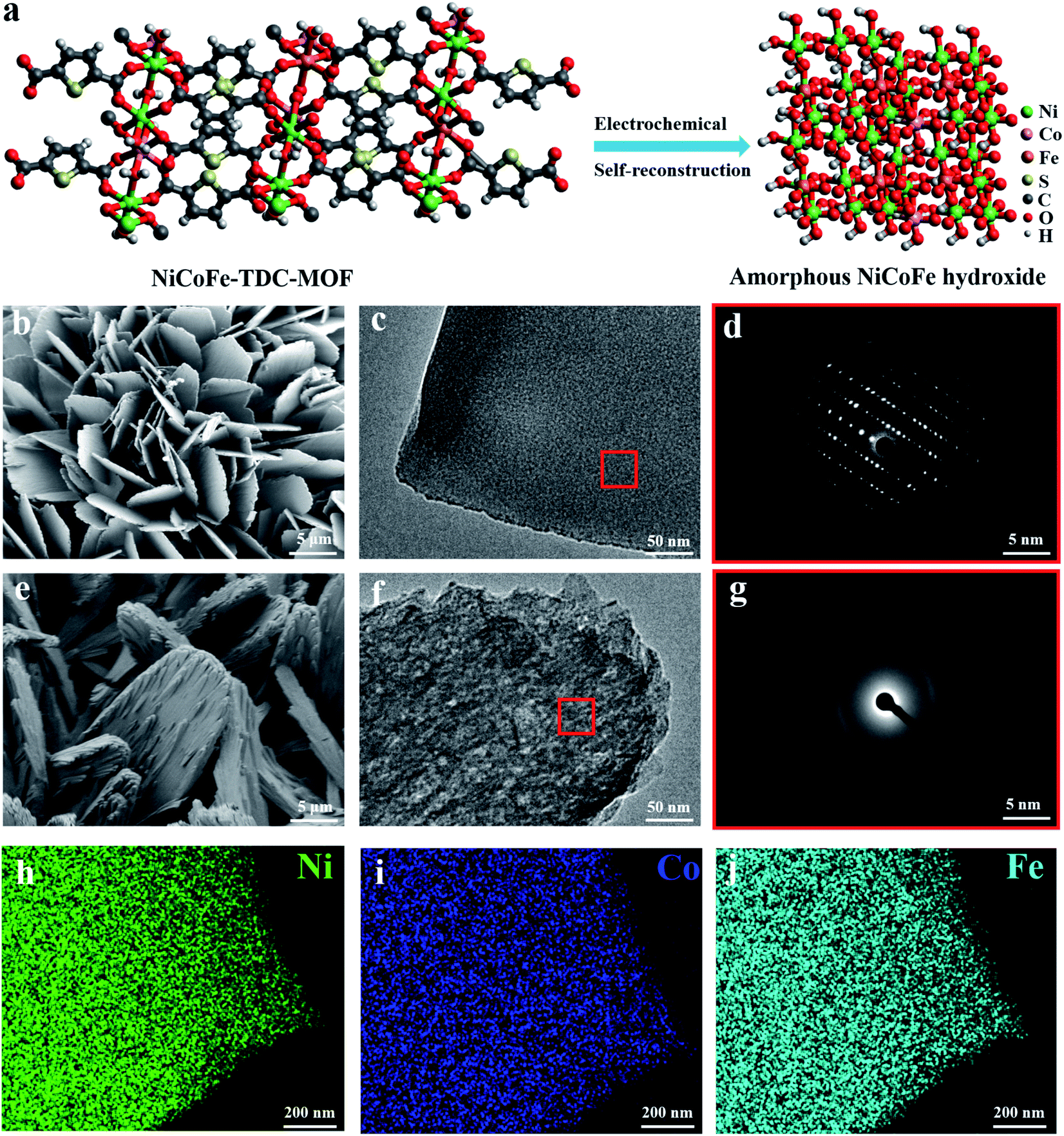 | ||
| Fig. 1 Structural characterization of NiCoFe-TDC and NiCoFe-TDC-AC. (a) Schematic diagram for the self-reconstruction result of the NiCoFe-TDC pre-catalyst under electro-oxidation conditions. (b) SEM image, (c) TEM images, and (d) the corresponding FFT spectrum of NiCoFe-TDC. (e) SEM image, (f) TEM images, and (g) the corresponding FFT spectrum of NiCoFe-TDC-AC. STEM EDX chemical maps for (h) Ni, (i) Co, and (j) Fe of a representative NiCoFe-TDC-AC nanosheet. | ||
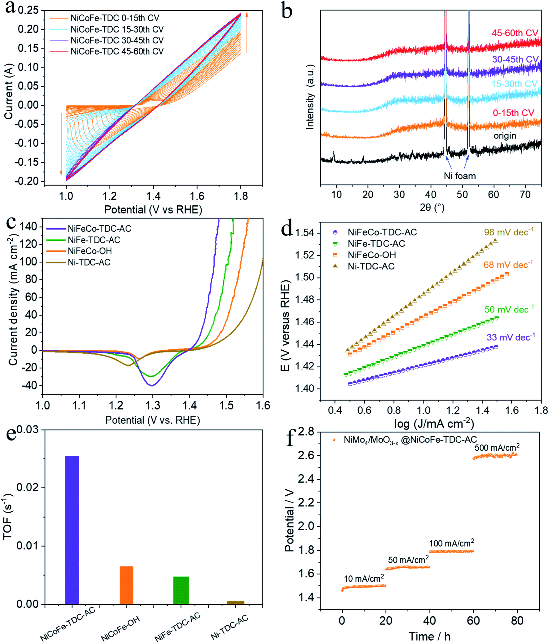 | ||
| Fig. 2 Evaluation of OER electrochemical activity on Ni foam. (a) CV curves of NiCoFe-TDC-AC at 50 mV s−1 scan rate. (b) Corresponding XRD spectrum of NiCoFe-TDC at different times of CV scan. (c) LSV curves of different catalysts at 1 mV s−1 scan rate with iR correction. (d) Tafel plots of NiCoFe-TDC-AC, NiFe-TDC-AC, NiCoFe-OH and Ni-TDC-AC. (e) TOF calculated from the current density at the iR-corrected overpotential of 300 mV. (f) Chronopotentiograms of NiMo4/MoO3−X@NiFe-TDC-AC at a constant current density of 10 mA cm−2, 50 mA cm−2, 100 mA cm−2, and 500 mA cm−2. | ||
Evaluation of electrochemical activity
To preliminarily investigate the electrochemical activation of NiCoFe-TDC, typical CV cycling was carried out in a 1 M KOH medium at a scan rate of 50 mV s−1 without iR compensation (pH = 13.8, Fig. 2a). Unexpectedly, the OER current increased significantly following the first 30 cycles (Fig. 2a). This increase in intensity is related to the continuous reconstruction of the amorphous hydroxide/oxyhydroxide species of NiCoFe-TDC-AC. The corresponding XRD spectrum of NiCoFe-TDC at different times of the CV scan shows that the MOFs were transformed into an amorphous structure and only the characteristic peaks of Ni foam existed after the first 15 cycles (Fig. 2b). The OER activities of the catalysts were evaluated using linear sweep voltammetry (LSV) at a scan rate of 1 mV s−1 with iR compensation (Fig. 2c). These catalysts were NiCoFe-based hydroxide, NiFe-based and Ni-based thiophene MOFs, named NiCoFe-OH, Ni-TDC-AC, and NiFe-TDC-AC, respectively. The activities of these catalysts were also characterized in terms of the OER for comparison. Among the four catalysts, Ni-TDC-AC exhibited the highest overpotential of 252 mV to reach a current density of 10 mA cm−2. NiCoFe-OH and NiFe-TDC showed better performance with overpotentials of 235 mV and 208 mV, respectively. NiCoFe-TDC-AC had the lowest overpotential of 191 mV and is outperformed by 44 mV as compared to NiCoFe-OH, which has the same metal active center but is synthesized by the hydrothermal method. Tafel slope analysis (Fig. 2d) confirmed the enhanced OER catalytic activity of NiCoFe-TDC-AC, for which we derived a value of 33 mV dec−1, which is much smaller than the values of 50 mV dec−1, 68 mV dec−1, and 98 mV dec−1 derived for NiFe-TDC, NiCoFe-OH, and Ni-TDC-AC, respectively. Interestingly, NiCoFe-TDC-AC was found to have a smaller double-layer capacitance of 1.42 mF cm−2 (Cdl), derived from the CV curves (Fig. S4–S6†), than NiCoFe-OH (3.67 mF cm−2) and NiFe-TDC-AC (5.02 mF cm−2), shown in Fig. S7.† In addition, we found that NiFe-TDC-AC has the largest electrochemical active surface area (ECSA) of 125.5 cm2 as compared to NiCoFe-OH (91.8 cm2) and NiCoFe-TDC-AC (35.5 cm2), suggesting the minimal exposed active sites of NiCoFe-TDC-AC. The polarization curves of the different samples were normalized by the ECSA. NiCoFe-TDC-AC still exhibited a better OER catalytic performance than NiCoFe-OH and NiFe-TDC-AC, indicating that the intrinsic activity of NiCoFe-TDC-AC is higher (Fig. S8†). A one-time constant model, which consists of solution resistance (Rs) in series with one parallel constant phase element resistance (CPE-Rct), fits the experimental data well at all the overpotentials tested (Fig. S9†). Electrochemical impedance spectroscopy (EIS) further indicated that NiCoFe-TDC-AC had the smallest charge transfer resistance (Rct, 1.40 Ω); thus, the fastest electrode kinetics is expected, as compared to Ni-TDC-AC (3.54 Ω), NiFe-TDC-AC (7.07 Ω), and NiCoFe-OH (42.69 Ω). The turnover frequency (TOF) is the most suitable metric to evaluate the OER activity.27–29 From our analysis, the NiCoFe-TDC-AC catalyst exhibits the highest TOF of 2.54 × 10⁻² s−1, which greatly exceeds those of NiCoFe-OH (6.50 × 10⁻³ s−1), NiFe-TDC-AC (4.71 × 10⁻³ s−1), and Ni-TDC-AC (1.4 × 10⁻⁵ s−1), as shown in Fig. 2e. This confirms the trend observed, suggesting that NiCoFe-TDC-AC is substantially more active than the others; the difference arising from the intrinsic structural and electronic differences. We synthesized a state-of-the-art HER catalyst, NiMo4/MoO3−X (Fig. S10†).30 The water splitting activity of NiMo4/MoO3−X with NiCoFe-TDC-AC was evaluated using a two-electrode system. The LSV curves (Fig. S11†) show an excellent water splitting performance of 1.46 V and 10 mA cm−2, indicating that this catalyst outperforms most previously reported noble-metal-free water splitting electrocatalysts (Table S2†). The stabilities of these two catalysts were investigated by chronopotentiometry at 10 mA cm−2, 50 mA cm−2, 100 mA cm−2, and 500 mA cm−2 (Fig. 2f). Notably, both catalysts exhibit excellent stability with negligible potential increases at current densities of 10 mA cm−2, 50 mA cm−2, and 100 mA cm−2. Even when the current density is 500 mA cm−2, the potential increase rate of the water splitting system is only 0.8 mV h−1. The ICP results of NiCoFe-TDC-AC after the OER stability test still exhibit similar molar ratios of Ni/Co (8.98:1) and Fe/Co (3.59:1) as of NiCoFe-TDC-AC, indicating that the elementary composition of the catalyst is consistent. Also, no Ni, Co and Fe ions were detected in the electrolyte before and after the ICP test, indicating that the material has excellent electrochemical stability (Table S3†).
Mechanistic investigations
To further identify the amorphous species and determine the actual process of self-reconstruction, Fourier transform infrared (FFT) spectra were obtained. First, we tested the original MOFs of NiCoFe-TDC and Ni-TDC. Characteristic thiophene peaks are clearly shown in Fig. S12 and S13.† For these MOFs after the electrochemical activation treatment of NiCoFe-TDC-AC and Ni-TDC-AC, these characteristic thiophene peaks nearly disappeared, further confirming the self-reconstruction.To identify the chemical states of these elements, X-ray photoelectron spectroscopy (XPS) and X-ray absorption spectroscopy (XAS) were performed. Fig. S14† shows the survey spectra of NiCoFe-TDC and NiCoFe-TDC-AC. NiCoFe-TDC mainly contains Ni, Fe, Co, C, S, and O, and the position of each peak was calibrated according to the position of C 1s (284.8 eV). For NiCoFe-TDC-AC, the peak of S disappeared, coinciding with the EDS mapping and ICP results (Fig. S15†). The change in the electronic structure of O was also investigated (Fig. S16†), where the dominant peaks of O 1s originating from O![[double bond, length as m-dash]](https://www.rsc.org/images/entities/char_e001.gif) C–O (531.50 eV) distinctly shifted to a lower binding energy of 531.03 eV from the M–O–M group, further demonstrating the formation of oxyhydroxide during the water oxidation process.31–35 The high-resolution spectrum of Ni 2p clearly reflects that the main Ni 2p3/2 of NiCoFe-TDC at 856.05 eV manifests a positive chemical shift of 0.62 eV relative to that of NiCoFe-TDC-AC (Fig. 3a). This could be ascribed to destruction of the metal–organic ligand and the Ni atom would be directly connected with the O atom, which would increase local electron density and thus result in the lower binding energy of Ni 2p in the form of hydroxide.36,37 Interestingly, two new peaks derived from Ni3+ with binding energies of 874.3 eV and 856.7 eV after electrochemical activation are observed, which could further confirm the electrochemical formation of NiOOH. Meanwhile, the disappearance of the characteristic peak of nickel foam is attributed to the oxidation of metal nickel on the surface to nickel oxide. The Co 2p3/2 spectrum of NiCoFe-TDC also shows a similar variation trend, indicating the possible structural evolution from MOF to CoOOH (Fig. 3c). On comparing the Fe 2p spectra of the NiCoFe-TDC before and after the electrochemical activation process (Fig. 3e), the peak of Fe 2p3/2 at 710.47 eV with a negative chemical shift of 0.62 eV relative to that of NiCoFe-TDC-AC (711.09 eV) is observed, indicating the generation of Fe3+ and self-construction.38 We confirmed this by analyzing the Ni, Co, and Fe K-edge X-ray absorption near edge structure (XANES) spectra (Fig. 3b, d and f). The K-edge energies of these three elements in NiCoFe-TDC-AC slightly shift to a higher absorption energy as compared to those of NiCoFe-TDC, indicating an increase in the valence state, which is consistent with the XPS results. These results further confirmed that the structure changed after electrochemical activation.
C–O (531.50 eV) distinctly shifted to a lower binding energy of 531.03 eV from the M–O–M group, further demonstrating the formation of oxyhydroxide during the water oxidation process.31–35 The high-resolution spectrum of Ni 2p clearly reflects that the main Ni 2p3/2 of NiCoFe-TDC at 856.05 eV manifests a positive chemical shift of 0.62 eV relative to that of NiCoFe-TDC-AC (Fig. 3a). This could be ascribed to destruction of the metal–organic ligand and the Ni atom would be directly connected with the O atom, which would increase local electron density and thus result in the lower binding energy of Ni 2p in the form of hydroxide.36,37 Interestingly, two new peaks derived from Ni3+ with binding energies of 874.3 eV and 856.7 eV after electrochemical activation are observed, which could further confirm the electrochemical formation of NiOOH. Meanwhile, the disappearance of the characteristic peak of nickel foam is attributed to the oxidation of metal nickel on the surface to nickel oxide. The Co 2p3/2 spectrum of NiCoFe-TDC also shows a similar variation trend, indicating the possible structural evolution from MOF to CoOOH (Fig. 3c). On comparing the Fe 2p spectra of the NiCoFe-TDC before and after the electrochemical activation process (Fig. 3e), the peak of Fe 2p3/2 at 710.47 eV with a negative chemical shift of 0.62 eV relative to that of NiCoFe-TDC-AC (711.09 eV) is observed, indicating the generation of Fe3+ and self-construction.38 We confirmed this by analyzing the Ni, Co, and Fe K-edge X-ray absorption near edge structure (XANES) spectra (Fig. 3b, d and f). The K-edge energies of these three elements in NiCoFe-TDC-AC slightly shift to a higher absorption energy as compared to those of NiCoFe-TDC, indicating an increase in the valence state, which is consistent with the XPS results. These results further confirmed that the structure changed after electrochemical activation.
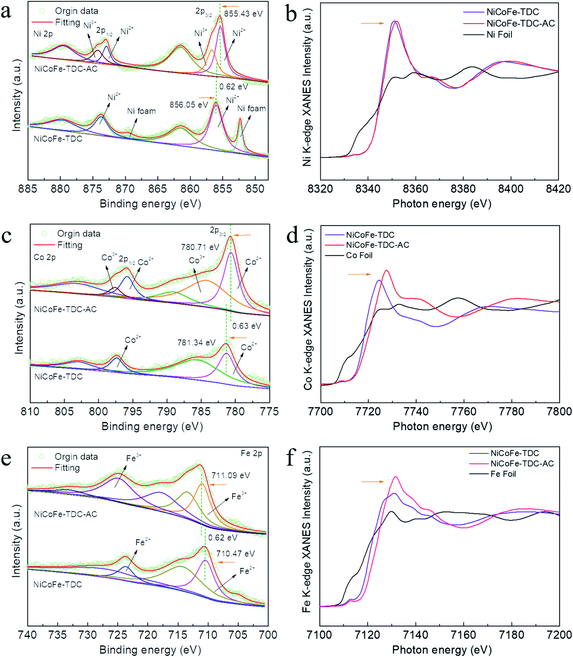 | ||
| Fig. 3 Electronic structure characterization and mechanistic investigations of NiCoFe-TDC and NiCoFe-TDC-AC. (a) High resolution Ni 2p, (b) normalized Ni K-edge XANES spectra, (c) high resolution Co 2p, (d) normalized Co K-edge XANES spectra, (e) high resolution Fe 2p, and (f) normalized Fe K-edge XANES spectra. | ||
Water splitting driven by monolithic perovskite/silicon tandem solar cell
To demonstrate the potential for unassisted solar-driven water splitting, a photovoltaic (PV) combined system is designed, where the perovskite/silicon tandem PV cell is under parallel illumination (Fig. 4a). For the perovskite single-junction device stack glass/ITO/NiOx/perovskite/C60/Au, the perovskite solar cell exhibited a power conversion efficiency (PCE) of 19.68% and a fill factor (FF) of 84% (Jsc = 20.38 mA cm−2, Voc = 1.15 V) (Fig. 4b). By integrating the external quantum efficiency (EQE) spectrum (Fig. S17†), we calculated a current density of 19.76 mA cm−2, which is in good agreement with the Jsc obtained from the J–V test. The stabilized efficiency was 19.36% after continuous operation at the maximum power point (MPP) for the 2000s (Fig. S18†). As illustrated in Fig. S19,† the monolithic perovskite/silicon tandem solar cell used in the solar water splitting system exhibited a PCE of 27.26% (Jsc = 19.1 mA cm−2, Voc = 1.78 V, and FF = 80%). Furthermore, under standard AM 1.5 G sunlight, it also exhibited an insignificant PCE loss after 60 min of operation (Fig. S20†). The perovskite cell and silicon cell show integrated current densities of 19.20 mA cm−2 and 19.16 mA cm−2, respectively, which are in good agreement with the Jsc of the J–V measurements (Fig. 4c). Finally, the practical water splitting performances of NiMo4/MoO3−X and NiCoFe-TDC-AC were evaluated via two-electrode measurements; the representative operating performance of the tandem cell is shown in Fig. 4d. From the intersection of the J–V curves, we can obtain the predicted operating current density of 18.16 mA cm−2 at a voltage of 1.49 V for the PV combined system. It is worth noting that the operating point of the water splitting cell is very close to the maximum power point of the perovskite tandem cell, indicating that minimal energy is lost when converting electrical energy into chemical energy in this system. Fig. 4e shows the long-term J–t test results and corresponding STH of the PV system under AM 1.5G 1 sun illumination at zero bias. The solar water splitting system shows a peak STH efficiency of approximately 21.32% (see detailed calculations in Formula 4†), which was calculated from the steady-state output of the average water splitting current density of 17.33 mA cm−2 in the first 120 min. This is the first time that an entirely earth-abundant material-based solar water splitting system achieved an STH efficiency of over 20%. More importantly, the solar water splitting system can still maintain an STH conversion of more than 20.43% after a stability test of >8 h.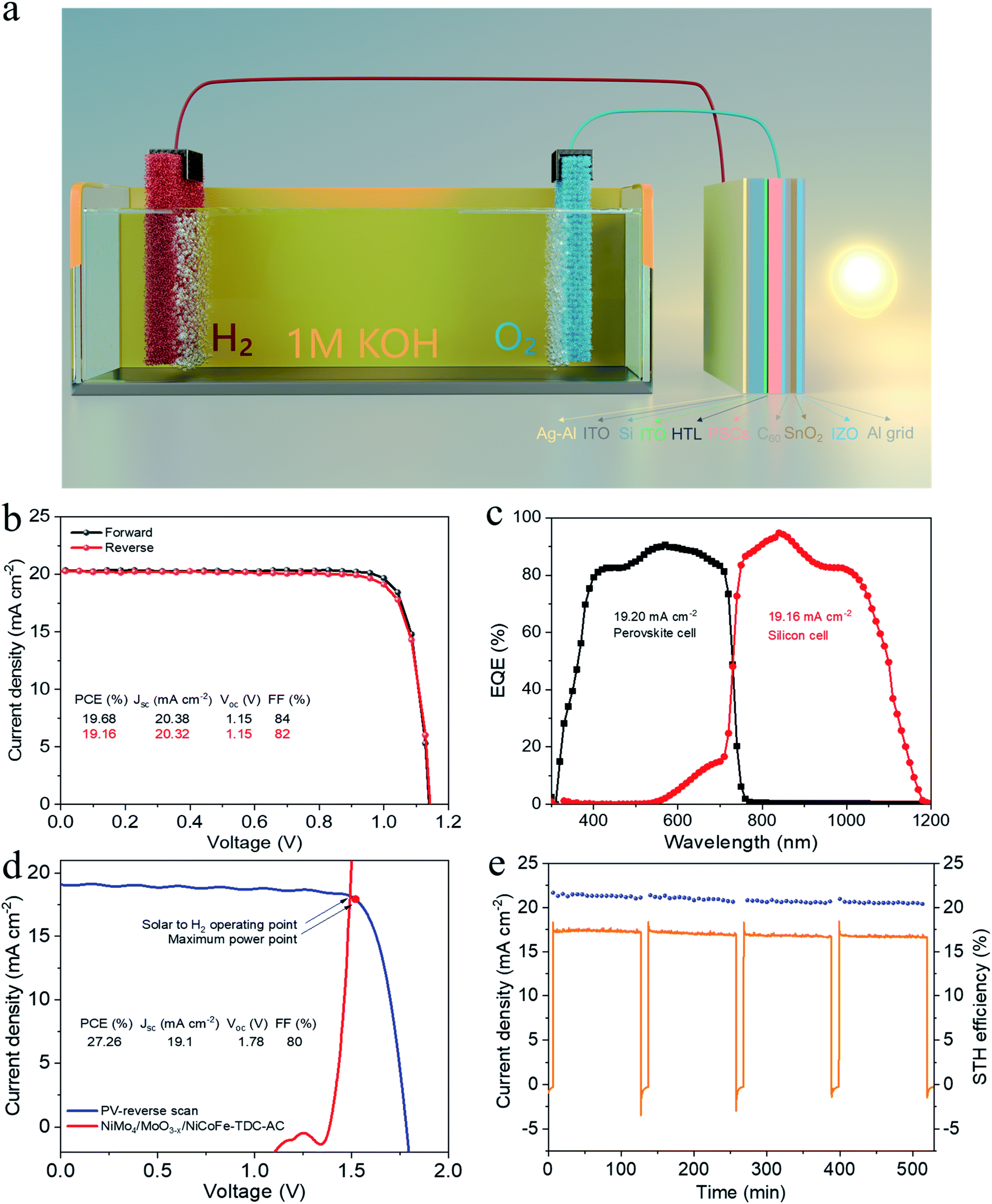 | ||
| Fig. 4 Solar-driven water splitting. (a) Schematic diagram of the solar-driven water splitting system. (b) J–V curves of the perovskite cell with forward and reverse scans. (c) EQE of the perovskite/silicon tandem PV Cell. (d) J–V curve of the perovskite/Si tandem solar cell from the reverse scan under simulated AM 1.5 G 100 mW cm−2 illumination and LSV curves of NiCoFe-TDC-AC and NiMo4/MnO3−X electrodes based on the two-electrode configuration without iR correction. The illuminated surface area of the tandem cell and the electrode was 0.5 cm2. (e) Long-term J–t test results and the corresponding STH for solar-driven water splitting system during continuous unassisted solar water splitting. | ||
Conclusions
In summary, we demonstrated that NiCoFe-based hydroxide nanosheets can be obtained from the complete electrochemical self-construction of thiophene MOFs, exhibiting a remarkable OER performance (191 mV at 10 mA cm−2). A monolithic perovskite/silicon tandem solar cell was used for unbiased solar water splitting by pairing NiCoFe-TDC-AC and NiMo4/MnO3−X as OER and HER catalysts, respectively. An unprecedented STH efficiency of over 20% based on a completely low-cost solar water splitting system was achieved under AM 1.5G 1 sun illumination. Based on this work, alternative strategies will be explored to control the degree of electrochemical self-reconstruction by further research for a more suitable precursor to develop robust and low-cost OER catalysts. Moreover, improving the performance of solar cells is expected to further enhance the overall STH efficiency.Data availability
The data that support the findings of this study are available from the corresponding author upon reasonable request.Author contributions
X. Z. and S. P. proposed the research and designed the experiments. S. P. carried out the experiments. R. L. completed the solar cell part. S. P. wrote the manuscript. C. C. and B. Z. helped carry out the XAFS test. Q. Z., M. W., B. S., P. W., C. Z. and Y. Z. helped perform the analysis. X. Z. improved the manuscript and contributed to the electrochemical analysis. All authors read and commented on the manuscript. X. Z. directed the overall project. S. P. and R. L. contributed equally to this work.Conflicts of interest
The authors declare no competing interests.Acknowledgements
The authors gratefully acknowledge the support from the National Key Research and Development Program of China (Grant No. 2018YFB1500103), the National Natural Science Foundation of China (Grant No. 61674084), the Overseas Expertise Introduction Project for Discipline Innovation of Higher Education of China (Grant No. B16027), Tianjin Science and Technology Project (Grant No. 18ZXJMTG00220), and the Fundamental Research Funds for the Central Universities, Nankai University (Grant No. 63201171 and 63201173). This work has also benefited from the 1W1B Beamline at Being Synchrotron Radiation Facility.References
- H. Dau, E. Fujita and L. Sun, ChemSusChem, 2017, 10, 4228–4235 CrossRef CAS PubMed.
- M. G. Walter, E. L. Warren, J. R. McKone, S. W. Boettcher, Q. Mi, E. A. Santori and N. S. Lewis, Chem. Rev., 2010, 110, 6446–6473 CrossRef CAS PubMed.
- DOE Technical Targets for Hydrogen Production from Photoelectrochemical Water Splitting, https://www.energy.gov/eere/fuelcells/doe, accessed, November 2020, accessed 4.
- J. Y. Jia, L. C. Seitz, J. D. Benck, Y. J. Huo, Y. S. Chen, J. W. D. Ng, T. Bilir, J. S. Harris and T. F. Jaramillo, Nat. Commun., 2016, 7, 1–6 Search PubMed.
- A. Nakamura, Y. Ota, K. Koike, Y. Hidaka, K. Nishioka, M. Sugiyama and K. Fujii, Appl. Phys. Express, 2015, 8, 107101 CrossRef.
- S. A. Bonke, M. Wiechen, D. R. MacFarlane and L. Spiccia, Energy Environ. Sci., 2015, 8, 2791–2796 RSC.
- A.-A. Amran, K. Eike, L. Bor, M. Artiom, H. Hannes, C. Pietro, J. A. Márquez, A. B. M. Vilches, K. Ernestas, J. A. Smith, P. Nga, M. Dorothee, G. Max, K. Lukas, S. Dieter, G. Christian, M. Tadas, J. Marko, M. Gašper, R. Bernd, S. Rutger, T. Marko, K. Lars, A. Antonio, S. Bernd, N. Dieter, S. Martin, U. Thomas, G. Vytautas and A. Steve, Science, 2020, 370, 1300–1309 CrossRef PubMed.
- J. Gao, F. Sahli, C. Liu, D. Ren, X. Guo, J. Werner, Q. Jeangros, S. M. Zakeeruddin, C. Ballif, M. Grätzel and J. Luo, Joule, 2019, 3, 2930–2941 CrossRef CAS.
- J. Song, C. Wei, Z. F. Huang, C. Liu, L. Zeng, X. Wang and Z. J. Xu, Chem. Soc. Rev., 2020, 49, 2196–2214 RSC.
- J. Zhao, J. J. Zhang, Z. Y. Li and X. H. Bu, Small, 2020, 16, 2003916 CrossRef CAS PubMed.
- W. T. Hong, M. Risch, K. A. Stoerzinger, A. Grimaud, J. Suntivich and Y. Shao-Horn, Energy Environ. Sci., 2015, 8, 1404–1427 RSC.
- Y. Lei, T. Xu, S. Ye, L. Zheng, P. Liao, W. Xiong, J. Hu, Y. Wang, J. Wang, X. Ren, C. He, Q. Zhang, J. Liu and X. Sun, Appl. Catal., B, 2020, 285, 119809 CrossRef.
- G. He, J. Li, H. Chen, J. Shi, X. Sun, S. Chen and X. Wang, Mater. Lett., 2012, 82, 61–63 CrossRef CAS.
- L. Xu, Q. Jiang, Z. Xiao, X. Li, J. Huo, S. Wang and L. Dai, Angew. Chem., Int. Ed. Engl., 2016, 55, 5277–5281 CrossRef CAS PubMed.
- Q. Xu, H. Jiang, X. Duan, Z. Jiang, Y. Hu, S. W. Boettcher, W. Zhang, S. Guo and C. Li, Nano Lett., 2020, 21, 492–499 CrossRef PubMed.
- J. Masa, P. Weide, D. Peeters, I. Sinev, W. Xia, Z. Sun, C. Somsen, M. Muhler and W. Schuhmann, Adv. Energy Mater., 2016, 6, 1502313 CrossRef.
- J. M. V. Nsanzimana, Y. Peng, Y. Y. Xu, L. Thia, C. Wang, B. Y. Xia and X. Wang, Adv. Energy Mater., 2018, 8, 1701475 CrossRef.
- B. You, N. Jiang, M. Sheng, M. W. Bhushan and Y. Sun, ACS Catal., 2015, 6, 714–721 CrossRef.
- F. Hu, S. Zhu, S. Chen, Y. Li, L. Ma, T. Wu, Y. Zhang, C. Wang, C. Liu, X. Yang, L. Song, X. Yang and Y. Xiong, Adv. Mater., 2017, 29, 1606570 CrossRef PubMed.
- K. Xu, P. Chen, X. Li, Y. Tong, H. Ding, X. Wu, W. Chu, Z. Peng, C. Wu and Y. Xie, J. Am. Chem. Soc., 2015, 137, 4119–4125 CrossRef CAS PubMed.
- P. Chen, K. Xu, Z. Fang, Y. Tong, J. Wu, X. Lu, X. Peng, H. Ding, C. Wu and Y. Xie, Angew. Chem., Int. Ed. Engl., 2015, 54, 14710–14714 CrossRef CAS PubMed.
- G. Ren, Q. Hao, J. Mao, L. Liang, H. Liu, C. Liu and J. Zhang, Nanoscale, 2018, 10, 17347–17353 RSC.
- K. Jayaramulu, J. Masa, O. Tomanec, D. Peeters, V. Ranc, A. Schneemann, R. Zboril, W. Schuhmann and R. A. Fischer, Adv. Funct. Mater., 2017, 24, 1700451 CrossRef.
- Y. R. Zheng, M. R. Gao, Q. Gao, H. H. Li, J. Xu, Z. Y. Wu and S. H. Yu, Small, 2015, 11, 182–188 CrossRef CAS PubMed.
- A. Sivanantham and S. Shanmugam, Appl. Catal., B, 2017, 203, 485–493 CrossRef CAS.
- T. Wu, S. Sun, J. Song, S. Xi, Y. Du, B. Chen, W. A. Sasangka, H. Liao, C. L. Gan, G. G. Scherer, L. Zeng, H. Wang, H. Li, A. Grimaud and Z. J. Xu, Nat. Catal., 2019, 2, 763–772 CrossRef CAS.
- F. Song and X. Hu, Nat. Commun., 2014, 5, 4477 CrossRef CAS PubMed.
- J. Guan, D. Li, R. Si, S. Miao, F. Zhang and C. Li, ACS Catal., 2017, 7, 5983–5986 CrossRef CAS.
- A. Moysiadou, S. Lee, C.-S. Hsu, H. M. Chen and X. Hu, J. Am. Chem. Soc., 2020, 142, 11901–11914 CrossRef CAS PubMed.
- Y. Y. Chen, Y. Zhang, X. Zhang, T. Tang, H. Luo, S. Niu, Z. H. Dai, L. J. Wan and J. S. Hu, Adv. Mater., 2017, 29, 1703311 CrossRef PubMed.
- S. Jin, ACS Energy Lett., 2017, 2, 1937–1938 CrossRef CAS.
- Z. Chen, L. Cai, X. Yang, C. Kronawitter, L. Guo, S. Shen and B. E. Koel, ACS Catal., 2018, 8, 1238–1247 CrossRef CAS.
- R. Zhang, P. A. Russo, A. G. Buzanich, T. Jeon and N. Pinna, Adv. Funct. Mater., 2017, 27, 1703158 CrossRef.
- Y.-H. F. a. Z.-P. Liu, J. Am. Chem. Soc., 2010, 132, 18214–18222 CrossRef PubMed.
- L.-A. Stern, L. Feng, F. Song and X. Hu, Energy Environ. Sci., 2015, 8, 2347–2351 RSC.
- R. Wang, C. Xu and J.-M. Lee, Nano Energy, 2016, 19, 210–221 CrossRef CAS.
- K. Rui, G. Zhao, Y. Chen, Y. Lin, Q. Zhou, J. Chen, J. Zhu, W. Sun, W. Huang and S. X. Dou, Adv. Funct. Mater., 2018, 28, 1801554 CrossRef.
- S. Klaus, Y. Cai, M. W. Louie, L. Trotochaud and A. T. Bell, J. Phys. Chem. C, 2015, 119, 7243–7254 CrossRef CAS.
Footnotes |
| † Electronic supplementary information (ESI) available. See DOI: 10.1039/d1ta03126k |
| ‡ Co-first authors. |
| This journal is © The Royal Society of Chemistry 2021 |