
Rigid two-dimensional indium metal–organic frameworks boosting nitrogen electroreduction at all pH values†
Yuntong
Sun
,
Baokai
Xia
 ,
Shan
Ding
,
Licheng
Yu
,
Sheng
Chen
* and
Jingjing
Duan
*
,
Shan
Ding
,
Licheng
Yu
,
Sheng
Chen
* and
Jingjing
Duan
*
Key Laboratory for Soft Chemistry and Functional Materials (Ministry of Education), School of Chemical Engineering, School of Energy and Power Engineering, Nanjing University of Science and Technology, Nanjing, 210094, China. E-mail: sheng.chen@njust.edu.cn; jingjing.duan@njust.edu.cn
First published on 23rd August 2021
Abstract
Based on an ion exchange and dissolution–recrystallization mechanism, rigid indium metal–organic framework (In-MOF) nanosheets have been synthesized under mild conditions. The collective advantages of the rigid structure and two-dimensional architecture (thickness: 1.3 nm) enable In-MOF to show great activity during nitrogen electroreduction and excellent stability over a wide pH range. At pH values <7, In-MOF nanosheets demonstrate an ammonia yield rate ≥ 24.70 μg h−1 mg−1 (or 4.94 μg h−1 cm−2) and faradic efficiency ≥6.72%. At pH values ≥7, 2D In-MOF can operate efficiently with a record NH3 yield of 79.20 μg h−1 mg−1 (or 15.94 μg h−1 cm−2) and faradic efficiency of 14.98%, making it one of the most active MOF-based electrocatalysts for nitrogen electroreduction. Furthermore, the reaction mechanism of nitrogen electroreduction has been revealed using density function theory (DFT) simulations, and it follows enzymatic pathways at all pH values, with the potential determining step being *H2NNH2* → *NH2 + NH3. It is expected that the present study will offer valuable clues for the design and fabrication of low-cost and efficient all-pH nitrogen reduction electrocatalysts for industrial applications.
Introduction
One of the most consumed chemicals in the world, ammonia (NH3) is still synthesized dominantly via the Haber–Bosch process, which was invented many years ago.1–4 This reaction takes place under harsh conditions with high temperatures (350–550 °C) and pressures (150–350 atm), consuming 1–2% of the annual global energy supply and discharging millions of tonnes of greenhouse gas (CO2).5–8 Recently, the less energy intensive and more sustainable approach of the electrochemical nitrogen reduction reaction (NRR) has gained extensive interests, as it can potentially produce NH3 from atmospheric N2 (from air), water, and renewable electricity (from solar and wind sources) under ambient conditions.9–11 Among the various available electrochemical technologies, proton exchange membrane (PEM) based NRR systems require acid-stable electrocatalysts to allow conditions with high concentrations of protons.12 Microbial electrolysis systems,13 which produce ammonia from waste organics using enzymes (e.g., nitrogenase), require NRR electrocatalysts that work in neutral media. Alkaline nitrogen electroreduction, on the other hand, necessitates the use of electrocatalysts that can operate under basic conditions to suppress the competing hydrogen evolution reaction (HER) when a reducing potential is applied.14,15 As such, to minimize production costs, efficient, selective, and stable NRR electrocatalysts that work at all pH values are highly desirable, but their development remains a significant challenge.Recently, metal nitrides, sulphides, oxides, and single-atom catalysts were predicted to be promising for the electrochemical NRR based on DFT studies, and some of them have been tested experimentally.16–18 However, the low NH3 yields and poor stability of these catalysts have greatly hindered their widespread application.18 Metal–organic frameworks (MOFs) represent a category of versatile functional material comprising metal ions coordinated with organic ligands.19–22 MOFs can show many intriguing characteristics, such as ultrahigh porosity, large specific surface areas, and plentiful unsaturated metal nodes, and thus, they have been extensively investigated for many applications.22–26 Nevertheless, the intrinsic structural instability of most MOFs has considerably restricted their long-term utilization.27,28
Very recently, a class of rigid MOF materials was reported,29,30 utilizing strongly bound metal–ligand orbital interactions and the rational selection of rigid organic linkers to minimize structural rotation/vibration. Therefore, these materials exhibit rigid porous channels between metal nodes and organic ligands, leading to strong durability and high efficiency during practical application. For example, Chen et al.29 reported an ultra-microporous MOF (Ca(C4O4)(H2O)) synthesized from calcium nitrate and squaric acid that possesses rigid one-dimensional channels for the efficient molecular sieving of ethane. In addition, Eubank and coauthors30 synthesized rigid iron carboxylate-based metal–organic frameworks with good adsorption and release properties toward nitric oxide. To the best of our knowledge, there have been no reports of rigid MOFs that can survive at all pH values thus far. Furthermore, the reported bulk MOFs have only small intrinsic microspores, limiting the transport of electrolyte and N2 gas during the NRR process. In response, downsizing rigid MOFs to low-dimensional materials, in particular two-dimensional (2D) nanosheets, can facilitate the formation of highly hierarchical meso/micro-porosity for feasible mass transport, and the ultrathin architecture allows for easy accessibility to active sites, leading to improved electrocatalytic performance.
Herein, we develop, for the first time, rigid 2D In-MOF nanosheets through a feasible synthesis strategy on the basis of fast ion exchange and dissolution–recrystallization mechanisms. This method is scalable and universal for the synthesis of other 2D MOFs, like Mn-MOF. The resulting ultrathin In-MOF nanosheets exhibit advantageous geometric structural and electrical properties, which are expected to contribute to outstanding NRR activity, high selectivity, and durable stability over the entire pH range. Furthermore, density function theory (DFT) calculations are carried out to reveal the reaction mechanisms and corresponding potential determining steps of the NRR at different pH values.
Results and discussion
Synthesis of rigid 2D In-MOF
As shown in Fig. 1a, 2D In-MOF nanosheets are prepared via a two-step procedure composed of a fast ion exchange process and a subsequent dissolution–recrystallization process. Firstly, similar to previously reported MOF synthesis,23,31,32 we directly mix an indium salt (indium chloride tetrahydrate, InCl3·4H2O) with an organic ligand (2,5-thiophene dicarboxylic acid, TDC). The mixed solution remained clear even after a long time, indicating that no products were formed during this process (ESI Fig. 1†). Inspired by the ion exchange process in the synthesis of traditional solid solutions,33 we introduce an intermediate agent in the form of cadmium acetate (Cd(Ac)2·3H2O). It is found that Cd2+ from cadmium acetate can coordinatively react with the TDC organic ligand to form Cd-MOF nanoparticles (ESI Fig. 2 and 3†). More interestingly, these Cd species inside the Cd-MOF architecture can be replaced by In3+ immediately, with a transformation into In-MOF nanoparticles (Fig. 1e and ESI Fig. 4†). Then, the effects of the mass percentage of Cd precursor (Cd(Ac)2·3H2O) in the mixed metal precursor (Cd(Ac)2·3H2O + InCl3·4H2O) were systematically examined. It can be concluded that a pure In-MOF phase only forms when Cd(Ac)2·3H2O accounts for 30–80 wt% in the metal salt precursor (ESI Fig. 5–12, ESI Note 1, and ESI Table 1†).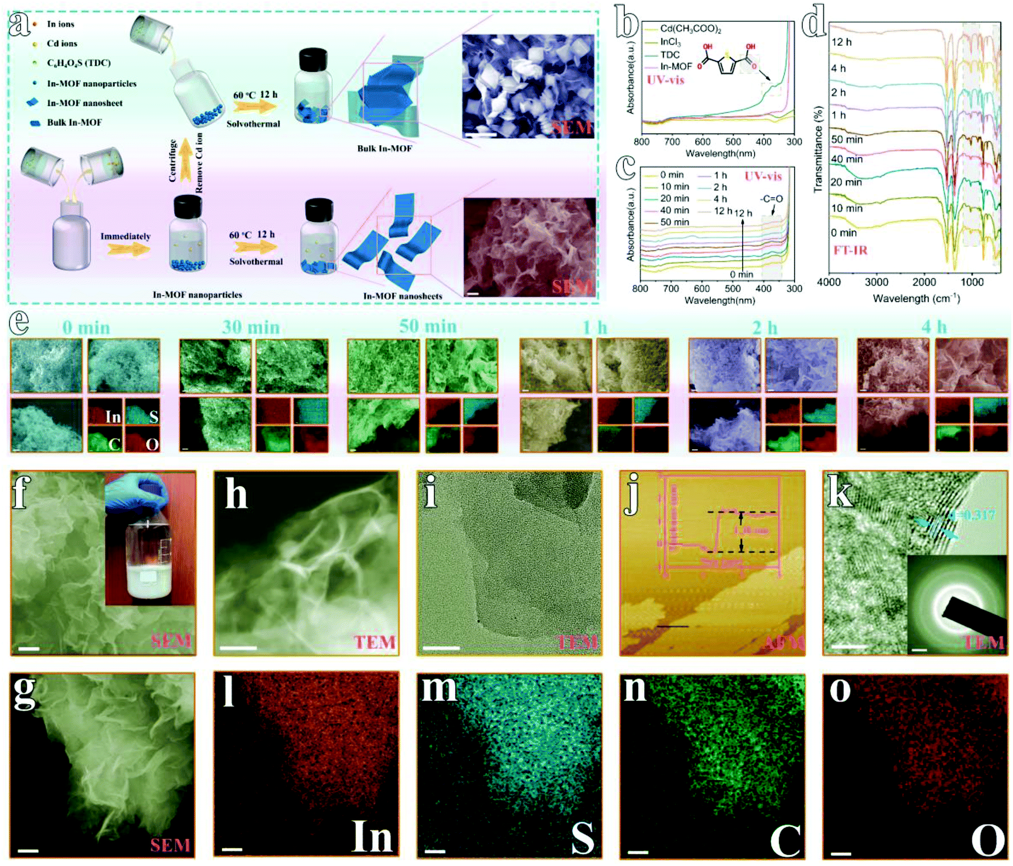 | ||
| Fig. 1 The synthesis and morphological characterization of 2D indium-metal–organic framework (In-MOF) nanosheets. (a) A schematic diagram of the synthesis of 2D and bulk In-MOFs (the scale bars in the SEM images on the right are 1 μm). (b) UV-vis spectra of 2D In-MOF nanosheets and their precursors in ethanol. Reaction intermediates during 2D In-MOF nanosheet synthesis at different times: (c) UV-vis spectra; (d) FT-IR spectra; and (e) SEM images and element mapping. Morphological characterization of 2D In-MOF: (f, g) SEM images (scale bars in f and g are 1 μm and 500 nm, respectively), the inset of (f) shows an optical image of the scalable synthesis of 2D In-MOF in a 1 liter container; (h, i) TEM images (scale bar: 200 nm for h and 50 nm for i); (j) an AFM image and the corresponding height profile; (k) a HRTEM image (scale bar: 5 nm), the inset of (k) shows the electron diffraction pattern (scale bar: 1/2 nm−1); (l–o) SEM element mapping of In, S, C, and O (scale bar: 500 nm). | ||
After the instant transformation of Cd-MOF into In-MOF, the reaction solution is still kept for 12 h at 60 °C, during which time the In-MOF nanoparticles are converted to 2D nanosheets. Note that Cd2+ plays an important role in this process because only large In-MOF nanoparticles are obtained in the absence of cadmium salt (Cd2+ is removed via centrifugation, ESI Fig. 13–16†). We further studied the formation mechanism via examining the reaction intermediates collected at different durations (from 0 min to 12 h, ESI Fig. 17†) using ultraviolet-visible (UV-vis) spectroscopy (Fig. 1c), Fourier transform infrared spectroscopy (FT-IR, Fig. 1d), scanning electron microscopy (SEM, Fig. 1e), and X-ray diffraction (XRD, ESI Fig. 18†). Among all the precursors (Fig. 1b), only the TDC organic ligand exhibits UV-vis absorption peaks in the wavelength range of 350–400 nm. Therefore, the reaction process can be monitored based on TDC. As shown in Fig. 1c, the UV-vis spectrum intensity does not change after 4 h, indicating that the reaction is completed by that stage. This result is consistent with that obtained from FT-IR studies (Fig. 1d). Further, SEM images (Fig. 1e) and XRD patterns (ESI Fig. 18†) indicate that more and more 2D In-MOF nanosheets appear with the depletion of large particles, which suggests that the reaction involves a dissolution–recrystallization mechanism.34 Significantly, we have extended the synthetic procedure to other intermediate agents and other MOFs, for example, In-MOF nanosheets obtained using Zn2+ as the intermediate agent (ESI Fig. 19†) and Mn-MOF nanosheets obtained using Cd2+ as the intermediate agent (ESI Fig. 20†). More importantly, the developed methodology is readily suitable for large-scale synthesis in a 1 liter container, producing 2.165 g of 2D In-MOF via one batch reaction (inset of Fig. 1f and ESI Fig. 21†).
Morphology and structural characterization of rigid 2D In-MOF
The morphology of 2D In-MOF has been characterized via SEM (Fig. 1f–h), showing a fluffy and anisotropic sheet architecture with a lateral size in the range of several micrometres. Notably, large open pores in the range of several micrometres formed between adjacent nanosheets, which can provide enormous ion and gas transport channels to promote electrocatalytic reactions. A close examination of an individual In-MOF nanosheet shows a smooth two-dimensional surface (Fig. 1i), an ultra-thin thickness of around 1.3 nm (Fig. 1j), and a lattice fringe of 0.317 nm (Fig. 1k) with a well-defined polycrystalline structure, as shown by the concentric circular rings in the SAED pattern (inset of Fig. 1k). These results are consistent with the element mapping images that show a uniform distribution of In, S, C, and O elements throughout the whole nanosheet (Fig. 1l–o). All the above characterization results explicitly indicate the successful synthesis of 2D In-MOF nanosheets. To examine the rigidity of the 2D In-MOF nanosheets, samples were treated in aqueous solution with different pH values (pH = 1, 7, and 12) and characterized via a number of techniques. Notably, SEM and element mapping images reveal little change in the morphology based on information relating to sheet lateral size, adjacent pores between sheets, and element distributions (ESI Fig. 22 and 23†). XRD studies indicate similar MOF crystal structures for samples treated at pH = 1, 7, and 12, which match well with the simulated pattern of In-MOF crystals (Fig. 2a). In addition, FT-IR spectra of all samples show similar vibration peaks from TDC organic ligands at different pH values. In comparison with TDC alone, there are no acidic carbonyl group signals, v(C![[double bond, length as m-dash]](https://www.rsc.org/images/entities/char_e001.gif) O), in the acid-treated sample (pH = 1) and no non-ionized carboxyl group signals, v(C–OH), in the alkaline-treated sample (pH = 12) (Fig. 2b–c), indicating that the organic ligands have been completely deprotonated and coordinated with indium species in the MOF architecture (Fig. 2b).
O), in the acid-treated sample (pH = 1) and no non-ionized carboxyl group signals, v(C–OH), in the alkaline-treated sample (pH = 12) (Fig. 2b–c), indicating that the organic ligands have been completely deprotonated and coordinated with indium species in the MOF architecture (Fig. 2b).
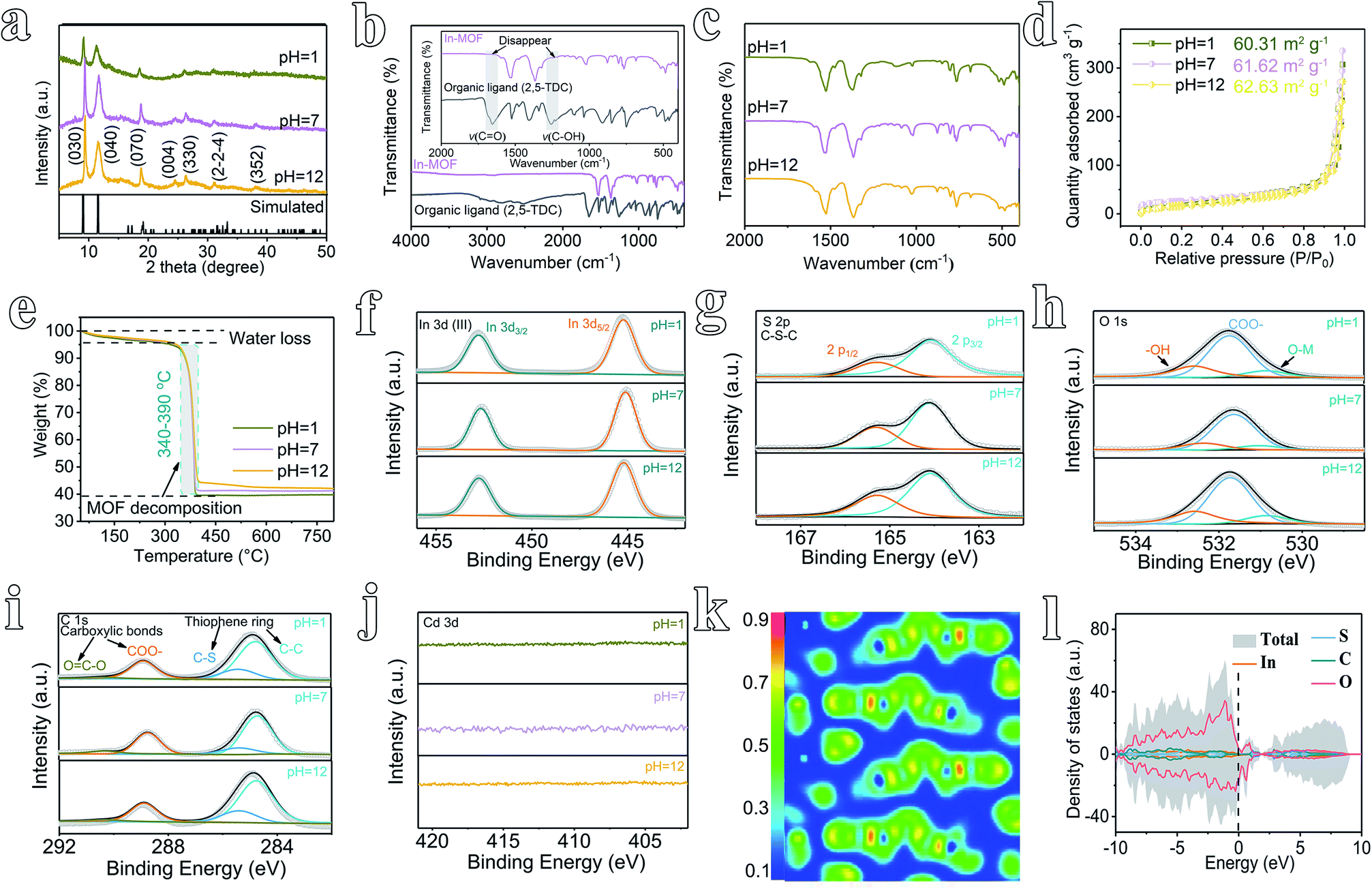 | ||
| Fig. 2 Structural characterization of rigid 2D In-MOF nanosheets after treatment in aqueous solutions with different pH values. (a) XRD patterns. (b and c) FT-IR spectra; the inset in (b) shows enlarged areas of FT-IR spectra between 2000 and 400 cm−2. (d) N2 adsorption–desorption isotherms. (e) TGA profiles. (f) In 3d, (g) S 2p, (h) O 1s, (i) C 1s, and (j) Cd 3d XPS spectra. (k) A theoretical electron location function (ELF) image of In-MOF sliced from the (100) plane. (l) Theoretical density of state (DOS) profiles. | ||
Moreover, the porosity of In-MOF after treatment has been characterized via nitrogen adsorption–desorption isotherm experiments. The derived Brunauer–Emmett–Teller (BET)35 surface areas of In-MOF are 60.31 m2 g−1 at pH = 1, 61.62 m2 g−1 at pH = 7, and 62.63 m2 g−1 at pH = 12 (Fig. 2d and ESI Table 2†). The corresponding pore volumes are 0.45 cm3 g−1 at pH = 1, 0.46 cm3 g−1 at pH = 7, and 0.48 cm3 g−1 at pH = 12 (ESI Table 2†). All the above results agree well with other characterization studies, including those carried out via thermogravimetric analysis (TGA, Fig. 2e), X-ray photoemission spectroscopy (XPS, Fig. 2f–j and ESI Fig. 24†), inductively coupled plasma mass spectrometry (ICP-MS, ESI Table 1†), and energy dispersive spectroscopy (EDS, ESI Fig. 25–27†), unambiguously confirming the excellent rigidity of the as-synthesized 2D In-MOF nanosheets at different pH values.
2D In-MOF nanosheets also demonstrate good electrical conductivity, as revealed by the computed electron location function (ELF) and density of states (DOS). As shown in Fig. 2k, the theoretical density functional theory (DFT) calculations of the correlation ELF value are around 0.5 between the metal nodes and adjacent organic ligands, indicating that 2D In-MOF has intrinsic metallic conductivity. This result matches well with DOS analysis (Fig. 2l). The DOS energies of atoms across the Fermi level are primarily below zero, thus indicating the intrinsically good conductivity of In-MOF. Indeed, the electrical conductivity of In-MOF can be further measured via a four-point probe system using pellets obtained via pressing MOF nanosheets.32 The average electrical conductivity of In-MOF is 8.3 S m−1, which is several orders of magnitude higher than traditional MOFs (10−6 S m−1).31
Electrocatalytic NRR performance of In-MOF at all pH values
Different from a conventional H-type electrochemical cell,36 a flow-type cell configuration has been assembled using In-MOF nanosheets decorated on a gas-diffusion layer (GDL) as the working electrode (mass loading: 0.2 mg cm−2), nickel foam (NF) as the counter electrode, and a saturated calomel electrode (SCE) as the reference electrode in different electrolytes (pH = 1, 2, 7, 12, and 14, ESI Fig. 28–30†). During electrochemical testing, catholyte and anolyte are pumped into the corresponding flow-cell chambers, which are separated by a Nafion membrane, while the NH3 product is pumped out and collected using acidic absorption chambers. Such a flow-type design can promote the mass transport of reactants and products. Further, the NRR principally includes two reaction processes: (i) 2N2 + 6H2O → 4NH3 + 3O2; and (ii) N2 + 2H2O → N2H4 + O2. Consequently, the plausible products can be analyzed via two methods: the indophenol blue method to detect ammonia (ESI Fig. 31–35†), and the Watt–Chrisp method to detect hydrazine (ESI Fig. 36 and 37†).Next, to quantify the NRR activity, chronoamperometric testing was conducted for 1 h at different applied current densities from 0.25 to 1.25 mA cm−2 (Fig. 3a–c and ESI Fig. 38†). At different pH values (pH = 1, 2, 7, 12, and 14), ammonia was produced, as evidenced by a strong UV-vis absorption signal at 655 nm (ESI Fig. 39 and 40†). In contrast, no hydrazine by-product is detected, which confirms that the feed N2 gas is converted only to ammonia during the NRR process catalyzed by as-prepared In-MOF (ESI Fig. 41†). Further, as shown in Fig. 3d–f and ESI Fig. 42–46,† the NH3 yield rates of In-MOF nanosheets at all pH values achieve maximum values at −0.5 mA cm−2, and they were 24.70 μg h−1 mg−1 (or 4.94 μg h−1 cm−2 (per unit area)) at pH = 1, 25.80 μg h−1 mg−1 (5.16 μg h−1 cm−2) at pH = 2, 64.73 μg h−1 mg−1 (12.95 μg h−1 cm−2) at pH = 7, 79.20 μg h−1 mg−1 (15.94 μg h−1 cm−2) at pH = 12, and 71.58 μg h−1 mg−1 (14.32 μg h−1 cm−2) at pH = 14. In addition, the faradic efficiencies (FEs) under neutral and alkaline conditions (pH = 7, 12, and 14) also increase in tandem with the NH3 yield rates, with highest FEs of 12.23% at pH = 7, 14.98% at pH = 12, and 13.54% at pH = 14 (Fig. 3e and f, and ESI Fig. 44–46†). The FEs in acidic electrolytes (pH = 1 and 2) continuously decline with current density from 0.25 to 1.25 mA cm−2, and the maximum FEs are 6.72% at pH = 1 and 7.50% at pH = 2 at −0.25 mA cm−2 (Fig. 3d and ESI Fig. 42 and 43†). According to the literature,37 the hydrogen evolution reaction (HER: H+ + e → 1/2H2) is a side process during the NRR. In comparison to alkaline and neutral counterparts (HER: 2H2O + 2e → H2 + 2OH−), the HER process works more favorably in acidic media (HER: 2H+ + 2e → H2, ESI Fig. 47†) and consumes more electrons that would otherwise take part in the NRR. Therefore, the NRR in neutral/alkaline electrolytes outperforms acidic electrolytes due to the HER being suppressed in media at pH ≥7. In addition, the changes in NH3 yields and FE with applied potential are also examined, and they are consistent with data obtained from changes in current density (ESI Fig. 48 and 49†).
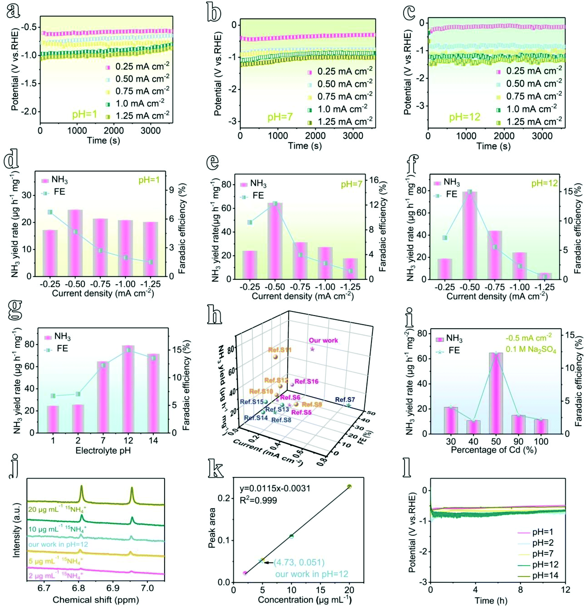 | ||
| Fig. 3 The nitrogen electroreduction performance of 2D In-MOF at all pH values. The chronoamperometric curves at pH values of (a) 1, (b) 7, and (c) 12. (d–f) The corresponding NH3 yield rates and faradic efficiencies (FEs) at different applied current densities. (g) NH3 yield rates and FEs at different pH values (the applied current is −0.5 mA cm−2). (h) A comparison of the NRR activity of our sample with several state-of-the-art electrocatalysts. These electrocatalysts have been marked in different colours according to the different pH values of the electrolytes used, where alkaline is pink, neutral is blue, and acidic is yellow. (i) A comparison of the activities of In-MOF samples prepared using different amounts of Cd precursor in the synthetic process. (j) 500 MHz 1H NMR spectra of NRR products tested using 15N2 feed gas and (k) the calibration curve of the 15NH4+ benchmark material. (l) Stability testing for 12 h at different pH values (the applied current is −0.5 mA cm−2). | ||
To understand the role of pH, we have plotted bar graphs illustrating the relationship between the NRR activity and pH (Fig. 3g and ESI Fig. 50†). Generally, the electrode demonstrates excellent NRR activity at all pH values from 1 to 14. Both NH3 yield rates and FEs increase with pH from 1 to 12, achieving maximum performance at pH = 12 (79.20 μg h−1 mg−1 and 14.98%), with a slight decline at pH = 14. Furthermore, normalized by ECSA (ESI Fig. 51†), the NH3 yield of 2D In-MOF is 1429.28 μg h−1 m−2, which is 2.41 and 3.26 times the yields of InCd-MOF and Cd-MOF, respectively. To the best of our knowledge, this NRR activity exceeds those of other reported MOF NRR electrocatalysts thus far (Fig. 3h and ESI Table 3†). The NRR performance is attributable to the excellent properties of the In-MOF nanosheets, including the 2D architecture, high specific surface area, and rigid structure, allowing for the wide exposure of active sites and good stability over a wide pH range. This can also be proved via examining the catalytic activity and stability of Cd-MOF for comparison (Fig. 3i and ESI Fig. 52–55†).
To verify that the produced NH3 originated from N2 electroreduction rather than external contamination, we conducted isotope labelling experiments using acid and alkaline treated 15N2 as the feed gas. As shown in Fig. 3j, the as-generated products were analyzed via 500 MHz 1H nuclear magnetic resonance (NMR) spectroscopy, and they showed the typical doublet signal of 15NH4+ rather than the triplet peaks of 14NH4+, thus indicating that NH3 originated from the NRR. Furthermore, the concentration of 15NH4+ can be quantified based on the peak area, giving similar catalytic activity in comparison to that obtained via the indophenol blue method (Fig. 3k). In addition, control experiments, including the use of blank carbon paper (CP, N2-saturated electrolyte, −0.5 mA cm−2) as the working electrode, open circuit potential testing (OCP, 2D In-MOF at N2-saturated electrolyte), and Ar gas-saturated electrolyte testing (2D In-MOF at −0.5 mA cm−2), generate negligible amounts of ammonia (ESI Fig. 56†). Further, 2D In-MOF shows excellent durability. It can operate at a steady current of 0.5 mA cm−2 for 12 h at pH values from 1 to 14 (Fig. 3l) with negligible morphological, structural, and element ratio changes (ESI Fig. 57–61 and ESI Table 1†). However, more C (72.4–79.2%) has been detected in comparison to a pristine 2D In-MOF nanosheet sample (51.6–56.7%), which originates from the carbon substrate. All of the results specifically confirm that rigid 2D In-MOF nanosheets are promising candidates to act as catalysts for large-scale nitrogen electroreduction to ammonia.
Mechanism study and discussion
To understand the origin of the electrocatalytic activity of 2D In-MOF nanosheets for the NRR at all pH values, DFT calculations are carried out. According to the XRD patterns in Fig. 2a, the as-formed In-MOF consists of alternating organic units (2,5-thiophenedicarboxylic acid group) and inorganic units (InO6), where the carboxyl group of each ligand bridges two metal atoms, and each metal ion coordinates with two opposite carboxyl groups and four equatorial ethanol molecules. Further, XPS studies (Fig. 2f–j) indicate that the material is composed of In, S, O, and C as main components. Accordingly, the In-MOF slab was built via cleaving a surface across a direction from bulk In-MOF. The slab is a sandwich structure, with the top and bottom layers containing indium atoms and the two layers linked via thiophene acid groups (ESI Fig. 62†). Next, we simulated the reaction pathway and Gibbs free energy changes (ΔG) of the NRR promoted by In-MOF surfaces. The ΔG values were calculated under standard conditions (0 °C, 100 kPa) without consideration of pH, solvation effects, or external potentials, which might be different from actual applied potentials during electrochemical reactions. While we have considered some parameters, like crystal box sizes (ESI Fig. 63†) and van der Waals forces (ESI Fig. 64†), they show little effect on the data in the present work.Generally, the NRR proceeds through four types of mechanisms: associative-distal, associative-alternating, dissociative, and enzymatic pathways (Fig. 4 and ESI Fig. 65 and 66†).38,39 Our systematic theoretical computation study reveals that In-MOF can promote the NRR via an enzymatic mechanism on the basis of this pathway having the lowest ΔG values in comparison to its counterparts (Fig. 4 and ESI Fig. 65 and 66†). Firstly, the NRR is illustrated as an N2 adsorption step followed by subsequent binding with six protons and electrons (* + N2 → *NN* → *HNN* → *HNNH* → *H2NNH* → *H2NNH2* →*NH2 + NH3→* + 2NH3, Fig. 4a, b). Initially, the ΔG value for N2 adsorption (*NN*) is 0.67 eV, which confirms feasible N2 activation on the catalyst. Next, the first hydrogenation step (*NN* + H+ → *HNN*) shows an energy barrier of 0.94 eV, followed by the *HNN* intermediate capturing the second, third and fourth (H+ + e) pairs to form *NHNH*, *H2NNH*, and *H2NNH2* with ΔG values of −0.31, 0.33, and −1.85 eV, respectively. Later, the highest energy barrier of 1.12 eV occurs for the fifth hydrogenation and first molecular NH3 production step (*H2NNH2* → *NH2 + NH3), which is considered to be the potential determining step for the NRR. Finally, the *NH2 intermediate is hydrogenated via successively adsorbing one (H+ + e) pair to produce one NH3 molecule with a corresponding ΔG value of −0.83 eV.
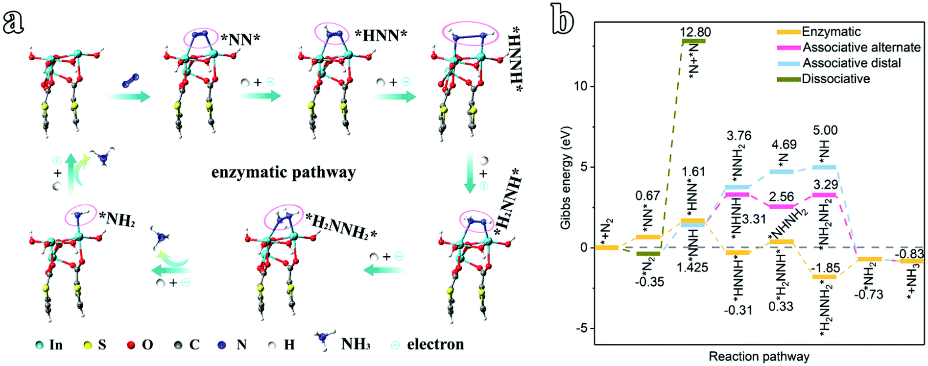 | ||
| Fig. 4 An electrocatalytic NRR mechanism study of the 2D In-MOF nanosheets. (a) Optimized structures for the enzymatic pathway. (b) The Gibbs free energy changes for possible NRR pathways. | ||
Further, we have investigated the origin of the prominent NRR activity of the 2D In-MOF nanosheets, which is associated with their outstanding properties, particularly the rigid interior structure allowing for robust stability at all pH values, the ultrathin 2D nanosheets providing highly exposed active sites, and the strong interactions between metal nodes (In) and conductive organic ligands boosting electrical conductivity. Firstly, the remarkable rigid properties of the 2D In-MOF nanosheets mean they can stably survive at different pH values, as verified by a series of structural and morphological characterization tests (Fig. 2 and ESI Fig. 22–27†). Specifically, SEM and element mapping images reveal little morphology change in In-MOF nanosheets at different pH values (Fig. 1f–o and ESI Fig. 22 and 23†), while XRD, FT-IR, BET, TGA, and XPS studies confirm the similar structure characteristics of In-MOF before and after acid and alkaline treatments (Fig. 2a–j). In addition, the In-MOF-based electrode shows excellent electrochemical stability, even after long-term operation at different pH values, as characterized via SEM, EDS, and XRD studies (ESI Fig. 57–61†).
Secondly, ultrathin (about 1.3 nm) 2D In-MOF nanosheets with large lateral size can expose large quantities of active sites to promote the NRR (Fig. 1f–j), which is evidenced based on their large surface area of 61.62 m2 g−1 and pore volume of 0.46 cm3 g−1 (Fig. 2d and ESI Table 2†). This phenomenon is also consistent with the electrochemically active surface area (ECSA) measurements, where the 2D In-MOF nanosheets (90.57 cm−2) exceed other counterparts, including In-MOF (30% Cd, 53.14 cm−2), In-MOF (40% Cd, 74.29 cm−2), InCd-MOF (50.57 cm−2), and Cd-MOF (52.57 cm−2) (ESI Fig. 67 and 68†). In addition, a fluffy structure formed involving these 2D nanosheets (ESI Fig. 57†) that can effectively prevent the dense packing of nanosheets, thus facilitating the rapid transport of electrolyte ions and N2 gas. This is revealed based on the obvious performance differences between 2D In-MOF nanosheets and other control samples, including In-MOF (30% Cd), In-MOF (40% Cd), InCd-MOF (90% Cd), and Cd-MOF (100% Cd); the NRR activities of these samples are 3.0, 6.0, 4.3, and 5.6 times smaller, respectively, than that of In-MOF nanosheets (64.73 μg h−1 mg−1 and 12.23%) (Fig. 3i and ESI Fig. 52†).
Thirdly, the excellent electrical conductivity is another contributor to the superior NRR performance, which is verified based on DFT calculations of the correlation ELF, which is around 0.5, and the DOS energies at the Fermi level (Fig. 2k, l). Electrochemical impedance spectroscopy (EIS) is also used to demonstrate the conductivity. According to the Nyquist diagrams shown in ESI Fig. 69,† the diameters of the semicircles indicate the charge-transfer resistance; the values for the comparison samples In-MOF (30% Cd), In-MOF (40% Cd), InCd-MOF, and Cd-MOF are roughly 5, 1.7, 2, and 4.7 times larger, respectively, than that of the 2D In-MOF nanosheets.
Finally, the design of a flow-cell configuration can reduce the transport resistance, facilitating the reaction kinetics at the three-phase interface to promote the NRR. At the same time, flowing electrolyte can bring a large amount of N2 feedstock to the catalyst surface and take away the generated NH3 sufficiently quickly. According to chemical equilibrium theory, the synthetic ammonia reaction (2N2 + 6H2O → 4NH3 + 3O2) shifts to the right, that is, more ammonia can be produced. This is verified based on the obvious performance differences between a flow-cell and H-cell. The NH3 yield rate and Faradic efficiency of 2D In-MOF in a flow-cell are 64.73 μg h−1 mg−1 and 12.23% in 0.1 M Na2SO4 electrolyte, which are roughly 6.2 and 5.5 times, respectively, those in a H-cell (ESI Fig. 70†).
Conclusions
In conclusion, based on a fast ion exchange and dissolution–recrystallization mechanism, rigid 2D In-MOF nanosheets have been successfully synthesized via a facile procedure under mild reaction conditions. 2D In-MOF features many remarkable properties, such as a rigid interior structure, ultrathin 2D nanolayers, rich porosity, and excellent electrical conductivity. Therefore, it can demonstrate outstanding nitrogen electroreduction activity, high selectivity, and durable stability at all pH values. Furthermore, DFT calculations reveal that the NRR promoted by 2D In-MOF follows an enzymatic mechanism across the entire pH range, and the potential determining step was identified to be *H2NNH2* → *NH2 + NH3. Note that the developed methodology is scalable and universal for the synthesis of other 2D MOF materials, like Mn-MOF, and it is highly promising for the application of MOFs in next-generation technology related to areas such as electrochemical sensors, batteries, and fuel cells.Author contributions
Yuntong Sun: methodology, data curation, writing – original draft. Baokai Xia: data curation, validation. Shan Ding and Licheng Yu: data curation. Sheng Chen: supervision, conceptualization. Jingjing Duan: conceptualization, writing – review & editing.Conflicts of interest
The authors declare no competing financial interests.Acknowledgements
The authors would like to acknowledge Dr Xin Tan from Australian National University for his helpful discussion relating to the DFT calculations. We also acknowledge financial support from the Basic Science Center Program for Ordered Energy Conversion of the National Natural Science Foundation of China (Grant No. 51888103), Jiangsu Natural Science Foundation (Grant No. BK20190460), Jiangsu innovative/entrepreneurial talent program, Natural Science Foundation (Grant No. 52006105), and Fundamental Research Funds for the Central Universities (Grant No. 30920041113 and 30921013103).References
- V. Smil, Nature, 1999, 400, 415 CrossRef CAS.
- L. C. Seefeldt, Z.-Y. Yang, D. A. Lukoyanov, D. F. Harris, D. R. Dean, S. Raugei and B. M. Hoffman, Chem. Rev., 2020, 120, 5082–5106 CrossRef CAS PubMed.
- T. N. Ye, S. W. Park, Y. Lu, J. Li, M. Sasase, M. Kitano, T. Tada and H. Hosono, Nature, 2020, 583, 391–395 CrossRef CAS PubMed.
- X. Zhang, E. A. Davidson, D. L. Mauzerall, T. D. Searchinger, P. Dumas and Y. Shen, Nature, 2015, 528, 51–59 CrossRef CAS PubMed.
- R. F. Service, Science, 2014, 345, 610 CrossRef CAS PubMed.
- C. Tang and S. Z. Qiao, Chem. Soc. Rev., 2019, 48, 3166–3180 RSC.
- C. J. M. van der Ham, M. T. M. Koper and D. G. H. Hetterscheid, Chem. Soc. Rev., 2014, 43, 5183–5191 RSC.
- P. Wang, F. Chang, W. Gao, J. Guo, G. Wu, T. He and P. Chen, Nat. Chem., 2017, 9, 64–70 CrossRef CAS PubMed.
- J. Wang, L. Yu, L. Hu, G. Chen, H. Xin and X. Feng, Nat. Commun., 2018, 9, 1795 CrossRef PubMed.
- Y. C. Hao, Y. Guo, L.-W. Chen, M. Shu, X.-Y. Wang, T.-A. Bu, W.-Y. Gao, N. Zhang, X. Su, X. Feng, J.-W. Zhou, B. Wang, C.-W. Hu, A.-X. Yin, R. Si, Y.-W. Zhang and C.-H. Yan, Nat. Catal., 2019, 2, 448–456 CrossRef CAS.
- C. Lv, L. Zhong, Y. Yao, D. Liu, Y. Kong, X. Jin, Z. Fang, W. Xu, C. Yan, K. N. Dinh, M. Shao, L. Song, G. Chen, S. Li, Q. Yan and G. Yu, Chem, 2020, 6, 2690–2702 CAS.
- J. Nash, X. Yang, J. Anibal, J. Wang, Y. Yan and B. Xu, J. Electrochem. Soc., 2017, 164, F1712–F1716 CrossRef CAS.
- P. Priecel and J. A. Lopez-Sanchez, ACS Sustain. Chem. Eng., 2018, 7, 3–21 CrossRef.
- S. Liu, M. Wang, T. Qian, H. Ji, J. Liu and C. Yan, Nat. Commun., 2019, 10, 3898 CrossRef PubMed.
- H. Cheng, P. Cui, F. Wang, L. X. Ding and H. Wang, Angew. Chem., Int. Ed., 2019, 58, 15541–15547 CrossRef CAS PubMed.
- Z. Wang, Z. Yu and J. Zhao, Phys. Chem. Chem. Phys., 2018, 20, 12835–12844 RSC.
- J. Zhao, J. Zhao and Q. Cai, Phys. Chem. Chem. Phys., 2018, 20, 9248–9255 RSC.
- G. Qing, R. Ghazfar, S. T. Jackowski, F. Habibzadeh, M. M. Ashtiani, C. P. Chen, M. R. Smith and T. W. Hamann, Chem. Rev., 2020, 120, 5437–5516 CrossRef CAS PubMed.
- S. L. James, Chem. Soc. Rev., 2003, 32, 276–288 RSC.
- H. C. Zhou, J. R. Long and O. M. Yaghi, Chem. Rev., 2012, 112, 673–674 CrossRef CAS PubMed.
- Z. Jiang, X. Xu, Y. Ma, H. S. Cho, D. Ding, C. Wang, J. Wu, P. Oleynikov, M. Jia, J. Cheng, Y. Zhou, O. Terasaki, T. Peng, L. Zan and H. Deng, Nature, 2020, 586, 549–554 CrossRef CAS PubMed.
- W. Wu, J. Su, M. Jia, Z. Li, G. Liu and W. Li, Sci. Adv., 2020, 6, eaax7270 CrossRef CAS PubMed.
- Z. Meng, J. Luo, W. Li and K. A. Mirica, J. Am. Chem. Soc., 2020, 142, 21656–21669 CrossRef CAS PubMed.
- S. Zhao, Y. Wang, J. Dong, C.-T. He, H. Yin, P. An, K. Zhao, X. Zhang, C. Gao, L. Zhang, J. Lv, J. Wang, J. Zhang, A. M. Khattak, N. A. Khan, Z. Wei, J. Zhang, S. Liu, H. Zhao and Z. Tang, Nat. Energy, 2016, 1 Search PubMed.
- Y. Peng, Y. Li, Y. Ban, H. Jin, W. Jiao, X. Liu and W. Yang, Science, 2014, 346, 1356–1359 CrossRef CAS PubMed.
- H. B. Wu and X. W. Lou, Sci. Adv., 2017, 3, eaap9252 CrossRef PubMed.
- C. Wang, X. Liu, N. Keser Demir, J. P. Chen and K. Li, Chem. Soc. Rev., 2016, 45, 5107–5134 RSC.
- S. Zhao, C. Tan, C.-T. He, P. An, F. Xie, S. Jiang, Y. Zhu, K.-H. Wu, B. Zhang, H. Li, J. Zhang, Y. Chen, S. Liu, J. Dong and Z. Tang, Nat. Energy, 2020, 5, 881–890 CrossRef CAS.
- R. B. Lin, L. Li, H. L. Zhou, H. Wu, C. He, S. Li, R. Krishna, J. Li, W. Zhou and B. Chen, Nat. Mater., 2018, 17, 1128–1133 CrossRef CAS PubMed.
- J. F. Eubank, P. S. Wheatley, G. Lebars, A. C. McKinlay, H. Leclerc, P. Horcajada, M. Daturi, A. Vimont, R. E. Morris and C. Serre, APL Mater., 2014, 2, 124112 CrossRef.
- D. Sheberla, J. C. Bachman, J. S. Elias, C. J. Sun, Y. Shao-Horn and M. Dinca, Nat. Mater., 2017, 16, 220–224 CrossRef CAS PubMed.
- D. Feng, T. Lei, M. R. Lukatskaya, J. Park, Z. Huang, M. Lee, L. Shaw, S. Chen, A. A. Yakovenko, A. Kulkarni, J. Xiao, K. Fredrickson, J. B. Tok, X. Zou, Y. Cui and Z. Bao, Nat. Energy, 2018, 3, 30–36 CrossRef CAS.
- C. R. McCormick and R. E. Schaak, J. Am. Chem. Soc., 2021, 143, 1017–1023 CrossRef CAS PubMed.
- J. Duan, S. Chen and C. Zhao, Nat. Commun., 2017, 8, 15341 CrossRef CAS PubMed.
- J. Park, A. C. Hinckley, Z. Huang, G. Chen, A. A. Yakovenko, X. Zou and Z. Bao, J. Am. Chem. Soc., 2020, 142, 20531–20535 CrossRef CAS PubMed.
- Y. Sun, T. Jiang, J. Duan, L. Jiang, X. Hu, H. Zhao, J. Zhu, S. Chen and X. Wang, ACS Catal., 2020, 10, 11371–11379 CrossRef CAS.
- Y. Ren, C. Yu, X. Tan, H. Huang, Q. Wei and J. Qiu, Energy Environ. Sci., 2021, 14, 1176–1193 RSC.
- Y. Sun, S. Ding, C. Zhang, J. Duan and S. Chen, J. Mater. Chem. A, 2021, 9, 1603–1609 RSC.
- Z. Fang, P. Wu, Y. Qian and G. Yu, Angew. Chem., Int. Ed., 2020, 60, 4275–4281 CrossRef PubMed.
Footnote |
| † Electronic supplementary information (ESI) available. See DOI: 10.1039/d1ta02684d |
| This journal is © The Royal Society of Chemistry 2021 |