 Open Access Article
Mechanically stable structured porous boron nitride with high volumetric adsorption capacity†
Tian
Tian
 a,
Jingwei
Hou
 b,
Humera
Ansari
 c,
Ying
Xiong
a,
Anouk
L'Hermitte
ad,
David
Danaci
 a,
Ronny
Pini
 c and
Camille
Petit
 *a
*a
aBarrer Centre, Department of Chemical Engineering, Imperial College London, South Kensington Campus, London SW7 2AZ, UK. E-mail: Camille.petit@imperial.ac.uk
bSchool of Chemical Engineering, University of Queensland, QLD 4072, Australia
cDepartment of Chemical Engineering, Imperial College London, South Kensington Campus, London SW7 2AZ, UK
dDepartment of Materials, Imperial College London, South Kensington Campus, London SW7 2AZ, UK
First published on 25th May 2021
Abstract
The development of adsorbents into structured and robust forms remains a challenge for emerging porous materials. In the context of porous boron nitride (BN), studies point to a tradeoff between mechanical stability, porosity, density, and adsorption kinetics. Approaches towards shaping and densification of porous BN have been mostly empirical since a detailed understanding of its formation mechanism, and how it impacts mechanical strength and porosity, is lacking. Here, we demonstrate a synthesis method that can directly produce a mechanically robust structured BN from an easily scalable polymeric precursor, which results in the highest volumetric surface area among porous BN samples to date. Structured BN exhibits a high bulk density (ca. 0.3 cm3 g−1), 50% higher than BN powders and over ten times higher than the structured BN aerogel, while maintaining fast sorption kinetics. Structured BN presents good mechanical strength, with hardness of 66.4 ± 4.5 MPa determined via microindentation, i.e. one to two orders of magnitude higher than reported structured aerogels. Using a range of material characterisation techniques, we propose a formation mechanism for structured BN. This formation mechanism reveals that the crosslinked intermediates are responsible for the high mechanical strength of the final material. Our approach produces a form of BN that addresses the limitations of other BN- and non BN-based adsorbents, and facilitates their application in gas separation and storage technologies.
1. Introduction
Owing to their high surface area, large porosity and rich surface functionalities, porous materials (e.g. zeolites, activated carbon, and metal–organic frameworks) can be used in a range of applications from catalysis to gas separation, and storage.1–3 Processing these materials from powders to robust densified structures (e.g. pellets, beads, and monoliths) represents a necessary step towards their industrial deployment. Indeed, powders suffer from limited mass transfer and poor mechanical strength and they are difficult to handle at scale.4,5 The large amount of interparticle space in powders also causes low bulk density and low volumetric adsorption/storage capacity,6,7 which in turn, leads to an increased footprint.8,9Shaping and densifying powders into mechanically robust structures can be done as follows: (i) mechanical compaction, (ii) application of binders, or (iii) growth on monolithic supports.7 These approaches usually result in decreased performance due to pore collapse from high-pressure, pore blockage from binders, or ‘dead’ volume from the support. Recently, Tian et al. developed a methodology towards the densification of metal–organic frameworks via a sol–gel method without using high-pressure compaction or binders, providing scope for the development of monolithic porous materials.9 However, the advances of producing other robust porous materials is still lacking, particularly for ceramics.10
Amorphous boron nitride (BN) represents a relatively new addition to the porous materials family,11–16 with recent studies demonstrating its use in molecular separation,13,17–22 catalysis,23 and drug delivery.24 Like other porous materials, identifying a way to shape and densify BN without compromising the porosity is needed. We note increasing focus towards producing structured BN in the recent literature. For example, BN aerogel, the most common form of structured BN, has been synthesised using various methods such as direct chemical reaction,25,26 carbonaceous template assisted method,27–29 or molecular substitution.30 Yet, all structured BN aerogels exhibit low density and mechanical strength, preventing their upscaling for practical adsorption applications. Sintering, another important method to synthesise structured BN, usually leads to a low surface area, albeit with high mechanical strength.31 Overall, these studies lead to two main observations: (i) a tradeoff persists between mechanical stability, porosity, density and adsorption kinetics; (ii) approaches towards shaping and densification of porous BN have been mostly empirical since a detailed understanding of porous BN formation mechanism and how it impacts mechanical strength and porosity is lacking. We hypothesise that higher bonding densities within BN will allow good resistance to deformation and loading. Hence, monitoring the formation mechanism of porous BN and linking it to mechanical strength will be important towards developing robust densified porous BN structures.
Herein, we present a method to synthesise structured BN, which exhibits high surface area, mechanical strength and enhanced volumetric adsorption capacity compared to powder BN. Structured BN also shows enhanced hydrolytic stability compared to BN powders, owing to a reduced oxygen content. Our method does not involve any compaction, binding or supporting step but instead relies on the use of a mechanically stable polymer precursor, a melamine-formaldehyde (MF) resin. MF resins have been well-developed at industry scale, making the current synthesis method suitable for upscaling. Through in-depth XPS and FTIR analyses, we determine the formation mechanism of structured BN starting from this polymer and how it influences the resulting mechanical stability.
2. Experimental section
2.1 Materials
Melamine (99%), urea (≥99.5%) and boric acid (≥99.5%) were purchased from Sigma-Aldrich; dicyandiamide (99.5%), and formaldehyde solution (37%) were purchased from Fisher. All chemicals were used as received. The gases used in this study, namely NH3 (99.98%), CH4 (99.5%), N2 (99.9995%), and Ar (99.999%) were purchased from BOC.2.2 Synthesis of structured and powder BN
A mechanically robust melamine–formaldehyde resin, referred to as MF resin, was used as the precursor to synthesise structured BN. The overall synthesis procedure is shown in Scheme 1 and described below.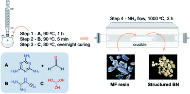 | ||
| Scheme 1 Schematic representation of structured BN synthesis via the formation of a melamine-formaldehyde resin (MF resin). A = melamine + formaldehyde; B = dicyandiamide, C = boric acid. | ||
2.3 Material characterisation
3. Results and discussion
3.1 Synthesis of structured BN
We used a macroporous melamine-formaldehyde (MF) resin as the precursor to produce structured BN (Scheme 1). To synthesise the porous MF resin, we employed dicyandiamide (DCD) as a foaming agent,35 and boric acid as the curing agent. The pore density in the MF resin was controlled by the DCD content and appears to impact the final morphology of the porous BN (Fig. 1). DCD acts as a porogen for the MF resin. Indeed, on the one hand, a low DCD content results in a non- or poorly porous MF resin, as indicated by the low ‘bubbles’ density observed on the microscope images (Fig. S1†). We attribute this behavior to the fact that gases generated during pyrolysis could not easily ‘escape’ through the tight resin, thus leading to pressure build-up and eventually structure collapse (Fig. 1a and b). On the other hand, a high DCD content formed a highly porous resin (Fig. S1†). We speculate that the low crosslink density (i.e. high porosity) of the resin meant that it was too fragile to withstand the chemical decomposition and gas release during pyrolysis, leading to the formation of powder (Fig. 1e). Overall, we have found that a DCD/melamine weight ratio of 0.72 resulted in a precursor with moderate pore density and high mechanical strength. In this case, the pores act as channels for the porogen to escape while the good crosslink density prevents the collapse of the macrostructure upon pyrolysis. As a result, we obtain a structured BN sample (Fig. 1c and d).Based on the observations above, we then focused our attention on the BN samples obtained using a 0.72 DCD/melamine weight ratio (Fig. 1d and S2†). We explored the effects of reaction atmosphere, reaction temperature and duration on the pyrolysis product to identify the optimal pyrolysis conditions. Looking first at the reaction atmosphere, we note significant differences between the products obtained under either NH3 or N2, starting from the colour: yellowish vs. black, respectively. As shown in Fig. S3†, the sample obtained under NH3 exhibits a higher BET specific surface area than that obtained under N2 (1513 m2 g−1vs. 216 m2 g−1). These differences result from the amount of active N-containing gases (e.g. NH3) during the synthesis. Under N2, the reactive N source comes principally from the resin and is insufficient for complete reaction with boric acid. Therefore, carbonization is predominant resulting in a black sample with a low surface area. In contrast, the synthesis under NH3 provides an excess of reactive N over a wide range of temperature, which is known to enhance the surface area of porous BN.20 Consequently, NH3 was selected as the reaction atmosphere for further tests.
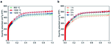
Next, we investigated the effects of the reaction temperature and the duration of the isothermal step. Keeping the duration at 3 h, the BET specific surface area increased from 1349 m2 g−1 at 800 °C to 1513 m2 g−1 at 1000 °C (Fig. 2a). Further increasing the reaction temperature to 1200 °C resulted in a decreased BET area (1397 m2 g−1), possibly due to a partial crystallization of BN.13,30 Furthermore, extending the duration of the isothermal step up to 3 h at 1000 °C enhanced the porosity (Fig. 2b). Beyond 3 h, the surface area reached a plateau, pointing towards a completion of the reactions leading to the gases release and porosity formation. To summarise, pyrolising the MF resin in NH3 atmosphere at 1000 °C for 3 h appeared the most effective method in obtaining structured BN and was used in the current work.
3.2 Characterisation of structured BN
We now analyse in more detail the features of structured BN obtained using the optimal conditions determined above. Fig. 3a shows the XRD pattern of the sample. The two broad peaks corresponding to (002) and (100) planes together with the absence of other reflections point to the presence of turbostratic/amorphous BN.30 The two main characteristic IR bands of BN at ∼1360 cm−1 (in-plane BN stretching) and at ∼810 cm−1 (out-of-plane B–N–B bending) are detected (Fig. 3b), confirming the chemical composition of structured BN.20 We attribute the additional small band at ∼1100 cm−1 to B–O bending mode.23 The presence of oxygen is further confirmed by XPS analyses, with a quantity of 3 at% (Fig. 3d). The lower oxygen content of structured BN compared to powder BN (3 at% vs. 9 at%) leads to a significant improvement of hydrolytic stability, an important feature for industrial application, as shown in Fig. S4 and S5†.36 SEM image of structured BN (Fig. 3c and S6†) reveals a continuous solid phase with slender cracks. The compact solid phase presents a relatively flat surface similar to other highly dense monolithic porous materials.8,9 The morphology is different from that of powders or aerogels, which contain a large amount of interparticle space.20,29 The slender cracks with macropores are distributed within the continuous flat surface and may result from the pores in the resin precursor. The pores propagated and enlarged under the stress generated during the synthesis, forming these gully-like cracks. TEM images in Fig. S7† reveal that the structured BN possesses disordered microstructure, which is supported by the fast Fourier transform (FFT) patterns. These analyses point to an amorphous nature of structured BN similar to powder BN.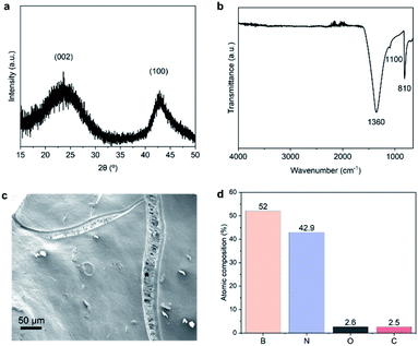 | ||
| Fig. 3 Structure, morphology and surface composition of structured BN. (a) XRD patterns; (b) FTIR spectrum; (c) SEM image; (d) XPS relative atomic percentages. | ||
3.3 Textural and gas adsorption properties of structured BN vs. powder BN
We evaluated the porosity of structured BN using the N2 adsorption isotherms at 77 K and compared it with a highly porous BN powder recently reported by our group (Table 1, Fig. S8†).20,23 Structured BN possesses a similar specific surface area to powder BN. However, different to powder BN which exhibits type IV isotherms (i.e. mesoporous material), structured BN exhibits a type I(b) isotherm, typical for materials with both micropores and narrow mesopores.37 The pore size distribution in Fig. S9† shows that the majority of the pores in structured BN are <2.5 nm. Furthermore, N2 sorption in structured BN plateaus for P/P0 > 0.5. On the contrary, N2 adsorption in powder BN increases towards high P/P0 values due to N2 condensation. This is due to the compact nature of structured BN, which results in minimal interparticle porosity.| S BET (mass) [m2 g−1] | V tot [cm3 g−1] | V micro [cm3 g−] | ρ [g cm−3] | S BET (vol) [m2 cm−3] | |
|---|---|---|---|---|---|
| Structured BN | 1523 | 0.79 | 0.56 | 0.31 | 473 |
| Powder BN | 1500 | 1.14 | 0.56 | 0.21 | 315 |
To quantify the compact nature of structured BN, we measured its bulk density using mercury porosimetry, a well-established technique that has been used to measure the bulk density of other porous materials.38 Mercury is a non-wetting liquid that does not intrude small pores at ambient pressure, which facilitates the measurement of bulk volume and thus the density (Section S4.2†). Table 1 shows the bulk density of structured BN was 0.31 g cm−3, nearly 50% higher than that of the bulk powder, which leads to a significantly higher volumetric BET area, achieving 473 m2 cm−3 (vs. 315 m2 cm−3 for powder BN). To densify the powder, we prepared BN pellets by compressing powder BN under 5 tonnes. Even though the bulk density improved (i.e. 0.43 g cm−3), the overall volumetric BET area remained lower than that of structured BN due to a lower gravimetric surface area (Fig. S8†) caused by the pore collapse. We note that structured BN aerogels usually exhibit bulk densities of 0.01–0.02 g cm−3,25,26,39–43 more than one order of magnitude lower than that of structured BN, ultimately leading to a low volumetric BET area (i.e. 0.1–14 cm2 cm−3). On the other hand, sintered structured BN typically shows high density but a low BET area (<450 m2 g−1),31 which results in a moderate volumetric BET area similar to the powder BN. Structured BN therefore exhibits the highest volumetric BET area for a BN sample published to date (Table S1†).
Volumetric methane storage capacity can be attractive for on board applications, where space for fuel is always a constraint. In these cases, the volumetric methane uptake is to be considered. Given the volumetric properties of structured BN, we performed CH4 adsorption isotherms at 298 K up to 70 bar. Fig. 4a shows that the absolute gravimetric uptake of structured BN is comparable to that of powder BN, owing to the similar surface area and micropore volume. Remarkably, structured BN shows a significant enhancement when considering the absolute volumetric adsorption capacity (59 vs. 42 (STP) cm3 cm−3 at 70 bar) as a result of the higher bulk density of structured BN (Fig. 4b and S10†).
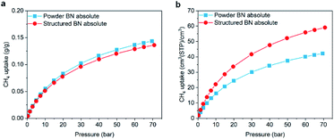 | ||
| Fig. 4 Comparison of absolute methane uptake at 298 K between powder BN (blue squares) and structured BN (red circles), (a) gravimetric capacity; (b) volumetric capacity. | ||
A higher material density often compromises adsorption kinetics due to the mass transfer limitation. To explore the adsorption kinetics of structured BN, we measured the adsorption equilibration time of N2 adsorption at an extremely low pressure (2.2 × 10⁻⁶ bar) at 77 K and compared the results likely to be the most visible, hence the selection of 2.2 × 10⁻⁶ bar for the measurement. Both samples show very fast adsorption kinetics, reaching equilibrium within 60 s (Fig. S11†). The small difference was mainly attributed to the lower macroporosity in structured BN, which results in a slightly lower diffusivity.
3.4 Mechanical stability of structured BN
Mechanical stability of adsorbents is an important property in practical applications as materials are always exposed to mechanical stress such as operational vibration and compression, i.e. weight of the packed adsorbent. As a preliminary and quick visual test of the mechanical robustness of structured BN, we first loaded a calibration weight onto the sample (Fig. S12†). Ca. 0.005 g of structured BN maintained its integral bulk structure under a 200 g calibration weight, pointing to an apparent robustness. We then evaluated quantitatively the hardness of the sample using microindentation. Our results show the hardness of structured BN is 66.4 ± 4.5 MPa, which is comparable to dense binder-free graphene oxide pellets44 and macroporous nickel foam.45 Remarkably, the hardness is 1–2 orders of magnitude higher than that reported for BN aerogels,46,47 suggesting a much higher resistance to plastic deformation, mainly attributed to the higher density.3.5 Formation mechanism of structured BN
Finally, we aimed to understand the formation mechanism of structured BN and its impact on the mechanical stability of the material by analysing the structural evolution from MF resin to structured BN. To do so, we collected samples obtained from the pyrolysis of MF resin under NH3 at different temperatures: 200, 300, 400, 600, 800 and 1000 °C. We then analysed the structural and chemical properties of these intermediates. Fig. 5 presents the optical images of the intermediates and highlights significant changes in aspect as the sample subsequently turned brown (300 °C), black (400 and 600 °C), brown (800 °C) and yellow (1000 °C). | ||
| Fig. 5 Optical images of melamine-formaldehyde resin (MF resin) heated at increasing temperatures under NH3 atmosphere. | ||
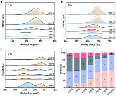
We used XPS to identify the chemical structure of the intermediates. The core level spectra of B1s, N1s and O1s are presented in Fig. 6a–c. The intermediate collected at 200 °C shows the typical melamine resin spectrum, namely two peaks located at 339.4 eV (pyrrodic N) and 398.2 eV (pyridinic N), respectively in N1s spectra and one peak at 287.6 eV assigned to triazine ring in C1s spectra.48,49 The absence of C–O peak suggests the resin is crosslinked via methylene bridges rather than ether bridges. Only a single peak at 192.2 eV corresponding to B–O in boron oxide is displayed in B1s spectra, indicating that boron oxide is physically interacted with resin at this temperature but not yet interacting chemically. At 300 °C, we observe the contribution of B–O–C bonds at 192 eV in B1s spectra.50,51 The appearance of this new bond is supported by the new C–O peak (286.4 eV) in C1s spectrum, revealing that chemical interactions between boron oxide and the MF resin start at 300 °C. Further increasing the temperature to 400 °C does not alter the B1s spectra. However, the main peak in C1s shifts to a higher binding energy. This observation together with the presence of graphitic N (400.3 eV) in N1s spectrum suggests the evolution from triazine to heptazine likely from the melon-based structure, an intermediate commonly observed in carbon nitride, g-C3N4, evolution.52,53 At 600 °C, we observe the formation of boronoxynitride, an important intermediate in forming porous BN, as evidenced by the new peaks at 191.2 eV (B1s) and 399.6 eV (N1s).19,47 Our findings show that all the boron atoms chemically interact with the resin skeleton by either via B–O–C or B–O–N bond at 600 °C. BN is subsequently formed at 800 °C, as evidenced by the peaks at 190.6 eV and 398.2 eV from B1s and N1s, respectively. The majority of carbon atoms are removed at this stage as seen in Fig. 6d and as suggested by the lighter colour of the 800 °C intermediate.54,55 Further increasing the temperature boosts carbon and oxygen removal and BN conversion through nitridation, resulting in a porous BN with a bright yellow colour. The structural evolution above is supported by the analysis from FTIR shown in Fig. S13.†
Based on the analysis above, we propose the structural evolution from MF resin to structured BN as shown in Fig. 7. First, methylene bridged MF resin bonds chemically to boron oxide via B–C–O. Then, the formation of a melon-based polymer takes place. Carbon atoms are gradually removed while the remaining compounds retain the crosslinked structure via B–O–C and B–O–N bonds. BN is then formed via a nitridation process and eventually the structured BN with minimum impurities is produced. Throughout structured BN formation, a crosslinked structure is maintained. This high bonding density in turns allows mechanical robustness to be preserved in the final product. This structural evolution study paves the way for further engineering of structured BN at larger scale.
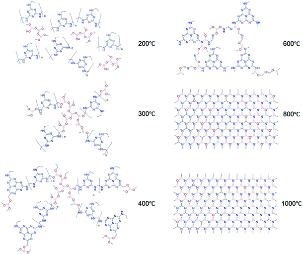 | ||
| Fig. 7 Proposed structural evolution of structured BN, using melamine-formaldehyde resin (MF resin) as a precursor and NH3 as the pyrolysis atmosphere. | ||
Conclusions
We have developed a structured BN using a porous melamine-formaldehyde resin as precursor. A suitable range of pore density in the precursor and a NH3 synthesis atmosphere are necessary to obtain porous structured BN. Compared to BN powders, structured BN exhibits an improved hydrolytic stability, a 50% higher bulk density and therefore an increased volumetric surface area, the highest among BN materials reported to date. As a result, structured BN displays an enhanced volumetric CH4 adsorption capacity, while sorption kinetics remains fast. Structured BN shows remarkable mechanical strength (i.e. hardness), being one to two orders of magnitude higher than that of aerogels. Studying the structured BN formation mechanism, we found that the polymer intermediates derived from the resin crosslink with boron atoms, which impart the mechanical stability to structured BN. The promising properties support the potential of structured BN for practical molecular adsorption applications and the formation mechanism study facilitates the industrial scale production of structured BN.Author contributions
T. T. and C. P. designed the research. T. T. performed the synthesis and characterisation, Y. X. carried out the XRD analyses, A. L. carried out the FTIR analyses and D. D. performed the N2 adsorption kinetics, all under the supervision of C. P. H. J. performed the micro-indentation. H. A. carried out the high pressure CH4 adsorption under the supervision of R. P. T. T. and C. P. wrote the manuscript. All the authors contributed to the final version.Conflicts of interest
There are no conflicts to declare.Acknowledgements
The authors would like to thank Dr Les Bolton for his technical input, Professor Jin-Chong Tan for his kind advices for mechanical stability tests and Professor Stephen Skinner for providing the lab space to conduct the synthesis. The authors would also like to acknowledge the funding and technical support from bp through the bp International Centre for Advanced Materials (bp-ICAM), which made this research possible as well as EPSRC for the funding through the CDT in Advanced Characterization of Materials (CDT-ACM) (EP/S515085/1) and the Impact Acceleration Account scheme (EP/R511547/1). D. D. and C. P. are grateful to the EPSRC for providing funding to undertake this research via the UK Carbon Capture and Storage Research Centre (UKCCSRC, grant EP/P026214/1). H. J. acknowledges the funding support from the Australian Research Council (DE190100803) and the University of Queensland (UQECR2057677).References
- B. M. Weckhuysen and J. Yu, Chem. Soc. Rev., 2015, 44, 7022–7024 RSC.
- M. R. Benzigar, S. N. Talapaneni, S. Joseph, K. Ramadass, G. Singh, J. Scaranto, U. Ravon, K. Al-Bahily and A. Vinu, Chem. Soc. Rev., 2018, 47, 2680–2721 RSC.
- H. C. J. Zhou and S. Kitagawa, Chem. Soc. Rev., 2014, 43, 5415–5418 RSC.
- M. I. Nandasiri, S. R. Jambovane, B. P. McGrail, H. T. Schaef and S. K. Nune, Coord. Chem. Rev., 2016, 311, 38–52 CrossRef CAS.
- A. Feinle, M. S. Elsaesser and N. Hüsing, Chem. Soc. Rev., 2016, 45, 3377–3399 RSC.
- Y. Peng, V. Krungleviciute, I. Eryazici, J. T. Hupp, O. K. Farha and T. Yildirim, J. Am. Chem. Soc., 2013, 135, 11887–11894 CrossRef CAS PubMed.
- J. Hou, A. F. Sapnik and T. D. Bennett, Chem. Sci., 2020, 11, 310–323 RSC.
- T. Tian, J. Velazquez-Garcia, T. D. Bennett and D. Fairen-Jimenez, J. Mater. Chem. A, 2015, 3, 2999–3005 RSC.
- T. Tian, Z. Zeng, D. Vulpe, M. E. Casco, G. Divitini, P. A. Midgley, J. Silvestre-Albero, J. C. Tan, P. Z. Moghadam and D. Fairen-Jimenez, Nat. Mater., 2018, 17, 174–179 CrossRef CAS PubMed.
- E. C. Hammel, O. L. R. Ighodaro and O. I. Okoli, Ceram. Int., 2014, 40, 15351–15370 CrossRef CAS.
- P. Dibandjo, F. Chassagneux, L. Bois, C. Sigala and P. Miele, J. Mater. Chem., 2005, 15, 1917–1923 RSC.
- S. Schlienger, J. Alauzun, F. Michaux, L. Vidal, J. Parmentier, C. Gervais, F. Babonneau, S. Bernard, P. Miele and J. B. Parra, Chem. Mater., 2012, 24, 88–96 CrossRef CAS.
- Q. Weng, X. Wang, Y. Bando and D. Golberg, Adv. Energy Mater., 2014, 4, 1–8 Search PubMed.
- J. Li, X. Xiao, X. Xu, J. Lin, Y. Huang, Y. Xue, P. Jin, J. Zou and C. Tang, Sci. Rep., 2013, 3, 1–7 Search PubMed.
- S. Marchesini, A. Regoutz, D. Payne and C. Petit, Microporous Mesoporous Mater., 2017, 243, 154–163 CrossRef CAS.
- J. Dai, X. Wu, J. Yang and X. C. Zeng, J. Phys. Chem. Lett., 2014, 5, 393–398 CrossRef CAS PubMed.
- Q. Weng, X. Wang, C. Zhi, Y. Bando and D. Golberg, ACS Nano, 2013, 7, 1558–1565 CrossRef CAS PubMed.
- J. Ye, X. Zhu, B. Cheng, J. Yu and C. Jiang, Environ. Sci. Technol. Lett., 2017, 4, 20–25 CrossRef CAS.
- S. Marchesini, X. Wang and C. Petit, Front. Chem., 2019, 7, 160 CrossRef CAS PubMed.
- S. Marchesini, C. M. McGilvery, J. Bailey and C. Petit, ACS Nano, 2017, 11, 10003–10011 CrossRef CAS PubMed.
- W. Lei, D. Portehault, D. Liu, S. Qin and Y. Chen, Nat. Commun., 2013, 4, 1777 CrossRef PubMed.
- F. Liu, J. Yu, X. Ji and M. Qian, ACS Appl. Mater. Interfaces, 2015, 7, 1824–1832 CrossRef CAS PubMed.
- R. Shankar, M. Sachs, L. Francàs, D. Lubert-Perquel, G. Kerherve, A. Regoutz and C. Petit, J. Mater. Chem. A, 2019, 7, 23931–23940 RSC.
- Q. Weng, B. Wang, X. Wang, N. Hanagata, X. Li, D. Liu, X. Wang, X. Jiang, Y. Bando and D. Golberg, ACS Nano, 2014, 8, 6123–6130 CrossRef CAS PubMed.
- J. Lin, X. Yuan, G. Li, Y. Huang, W. Wang, X. He, C. Yu, Y. Fang, Z. Liu and C. Tang, ACS Appl. Mater. Interfaces, 2017, 9, 44732–44739 CrossRef CAS PubMed.
- G. Li, M. Zhu, W. Gong, R. Du, A. Eychmüller, T. Li, W. Lv and X. Zhang, Adv. Funct. Mater., 2019, 29, 1–7 Search PubMed.
- M. Rousseas, A. P. Goldstein, W. Mickelson, M. A. Worsley, L. Woo and A. Zettl, ACS Nano, 2013, 7, 8540–8546 CrossRef CAS PubMed.
- Y. Song, B. Li, S. Yang, G. Ding, C. Zhang and X. Xie, Sci. Rep., 2015, 5, 1–9 Search PubMed.
- X. Xu, Q. Zhang, M. Hao, Y. Hu, Z. Lin, L. Peng, T. Wang, X. Ren, C. Wang, Z. Zhao, C. Wan, H. Fei, L. Wang, J. Zhu, H. Sun, W. Chen, T. Du, B. Deng, G. J. Cheng, I. Shakir, C. Dames, T. S. Fisher, X. Zhang, H. Li, Y. Huang and X. Duan, Science, 2019, 363, 723–727 CrossRef CAS PubMed.
- Y. Xue, P. Dai, X. Jiang, X. Wang, C. Zhang, D. Tang, Q. Weng, X. Wang, A. Pakdel, C. Tang, Y. Bando and D. Golberg, J. Mater. Chem. A, 2015, 4, 1469–1478 RSC.
- S. Bernard and P. Miele, New J. Chem., 2014, 38, 1923–1931 RSC.
- S. Brunauer, P. H. Emmett and E. Teller, J. Am. Chem. Soc., 1938, 60, 309–319 CrossRef CAS.
- S. G. Chen and R. T. Yang, Langmuir, 1994, 10, 4244–4249 CrossRef CAS.
- H. Ansari, L. Joss, J. Hwang, J. P. M. Trusler, G. Maitland and R. Pini, Microporous Mesoporous Mater., 2020, 308, 110537 CrossRef CAS.
- US Pat., 3 931 064, 1976 Search PubMed.
- R. Shankar, S. Marchesini and C. Petit, J. Phys. Chem. C, 2019, 123, 4282–4290 CrossRef CAS.
- M. Thommes, K. Kaneko, A. V. Neimark, J. P. Olivier, F. Rodriguez-Reinoso, J. Rouquerol and K. S. W. Sing, Pure Appl. Chem., 2015, 87, 1051–1069 CAS.
- H. Giesche, in Handbook of Porous Solids, Wiley-VCH Verlag GmbH, Weinheim, Germany, 2008, pp. 309–351 Search PubMed.
- J. G. Alauzun, S. Ungureanu, N. Brun, S. Bernard, P. Miele, R. Backov and C. Sanchez, J. Mater. Chem., 2011, 21, 14025–14030 RSC.
- X. Zeng, L. Ye, S. Yu, R. Sun, J. Xu and C. P. Wong, Chem. Mater., 2015, 27, 5849–5855 CrossRef CAS.
- Y. Joo Jeong and M. F. Islam, Nanoscale, 2015, 7, 12888–12894 RSC.
- M. Wang, T. Zhang, D. Mao, Y. Yao, X. Zeng, L. Ren, Q. Cai, S. Mateti, L. H. Li, X. Zeng, G. Du, R. Sun, Y. Chen, J. Bin Xu and C. P. Wong, ACS Nano, 2019, 13, 7402–7409 CrossRef CAS PubMed.
- W. Lei, V. N. Mochalin, D. Liu, S. Qin, Y. Gogotsi and Y. Chen, Nat. Commun., 2015, 6, 1–8 Search PubMed.
- C. N. Yeh, H. Huang, A. T. O. Lim, R. H. Jhang, C. H. Chen and J. Huang, Nat. Commun., 2019, 10, 422 CrossRef CAS PubMed.
- J. H. Pikul, S. Özerinç, B. Liu, R. Zhang, P. V. Braun, V. S. Deshpande and W. P. King, Sci. Rep., 2019, 9, 1–12 CAS.
- H. Kashani, Y. Ito, J. Han, P. Liu and M. Chen, Sci. Adv., 2019, 5, 1–7 Search PubMed.
- T. Woignier, J. Primera, A. Alaoui, F. Despetis, S. Calas-Etienne, A. Faivre, L. Duffours, C. Levelut and P. Etienne, J. Sol-Gel Sci. Technol., 2020, 93, 6–27 CrossRef CAS.
- S. Zhuang, E. S. Lee, L. Lei, B. B. Nunna, L. Kuang and W. Zhang, Int. J. Energy Res., 2016, 40, 2136–2149 CrossRef CAS.
- A. Deryło-Marczewska, J. Goworek, S. Pikus, E. Kobylas and W. Zgrajka, Langmuir, 2002, 18, 7538–7543 CrossRef.
- J. Jana, M. Ganguly, K. R. S. Chandrakumar, G. M. Rao and T. Pal, Langmuir, 2017, 33, 573–584 CrossRef CAS PubMed.
- H. Fang, C. Yu, T. Ma and J. Qiu, Chem. Commun., 2014, 50, 3328–3330 RSC.
- S. Dyjak, W. Kiciński and A. Huczko, J. Mater. Chem. A, 2015, 3, 9621–9631 RSC.
- T. S. Miller, A. B. Jorge, T. M. Suter, A. Sella, F. Corà and P. F. McMillan, Phys. Chem. Chem. Phys., 2017, 19, 15613–15638 RSC.
- Y. Gong, G. Shi, Z. Zhang, W. Zhou, J. Jung, W. Gao, L. Ma, Y. Yang, S. Yang, G. You, R. Vajtai, Q. Xu, A. H. Macdonald, B. I. Yakobson, J. Lou, Z. Liu and P. M. Ajayan, Nat. Commun., 2014, 5, 3193 CrossRef PubMed.
- C. Wu, B. Wang, N. Wu, C. Han, X. Zhang, S. Shen, Q. Tian, C. Qin, P. Li and Y. Wang, Ceram. Int., 2020, 46, 1083–1090 CrossRef CAS.
Footnote |
| † Electronic supplementary information (ESI) available: microscope images, N2 adsorption isotherms and kinetics, moisture stability, bulk density test, methane high pressure adsorption, mechanical stability, FTIR. See DOI: 10.1039/d1ta02001c |
| This journal is © The Royal Society of Chemistry 2021 |


