
 Open Access Article
 This Open Access Article is licensed under a Creative Commons Attribution-Non Commercial 3.0 Unported Licence
Phase evolution of electrochemically potassium intercalated graphite†
Hiroo
Onuma
a,
Kei
Kubota
 ab,
Shotaro
Muratsubaki
a,
Wataru
Ota
c,
Maxim
Shishkin
b,
Hirofumi
Sato
bce,
Koichi
Yamashita
bd,
Satoshi
Yasuno
f and
Shinichi
Komaba
*ab
ab,
Shotaro
Muratsubaki
a,
Wataru
Ota
c,
Maxim
Shishkin
b,
Hirofumi
Sato
bce,
Koichi
Yamashita
bd,
Satoshi
Yasuno
f and
Shinichi
Komaba
*ab
aDepartment of Applied Chemistry, Tokyo University of Science, 1-3 Kagurazaka, Shinjuku-ku, Tokyo 162-8601, Japan. E-mail: komaba@rs.tus.ac.jp
bElements Strategy Initiative for Catalysts and Batteries (ESICB), Kyoto University, 1-30 Goryo-Ohara, Nishikyo-ku, Kyoto 615-, 8245, Japan
cDepartment of Molecular Engineering, Kyoto University, Nishikyo-ku, Kyoto 615-8510, Japan
dDepartment of Chemical System Engineering, Graduate School of Engineering, The University of Tokyo, 7-3-1 Hongo, Bunkyo-ku, Tokyo 113-8656, Japan
eFukui Institute for Fundamental Chemistry, Kyoto University, Takano-Nishibiraki-cho 34-4, Sakyou-ku, Kyoto 606-8103, Japan
fJapan Synchrotron Radiation Research Institute (JASRI), 1-1-1 Kouto, Sayo-gun, Hyogo, 679-5198, Japan
First published on 31st March 2021
Abstract
Graphite is commonly known as a layered material to accommodate alkali metal ions between graphene layers and is used as a negative electrode material of most Li-ion batteries and for developing K-ion batteries. Phase evolution of graphite during chemical K-vapor intercalation was well studied in the 1920s–1980s, but that during electrochemical (de)potassiation is different and not fully clarified yet. Herein, we elucidate the phase evolution behaviors of electrochemically potassium intercalated graphite by operando X-ray diffraction in comparison to those of a Li system based upon optimizing the graphite electrode and electrolyte conditions for precise analysis. The operando diffraction data and first-principles calculations results reveal staging transformations from graphite to stage-1 KC8 through disorderly stacked high stage, stage 4L, stage 3L, stage 2L, and stage 1 phases and reversal transitions including hysteresis. Based on the experimental and theoretical data, we propose structural change mechanisms of graphite during electrochemical K-intercalation and deintercalation on the basis of Daumas–Hérold defects and the defect disappearance by complete K-intercalation.
Introduction
From the 1990s onward, graphite has been broadly used as a negative electrode material in most Li-ion batteries owing to high gravimetric and volumetric capacities, low operation potential, and high electronic conductivity.1–3 Electrochemical lithium intercalation (lithiation) into highly crystalline graphite proceeds through formation of staged lithium graphite intercalation compounds (Li-GICs). In the 1950s–1970s, Li-GICs were chemically prepared by lithium-vapor synthesis4 or annealing techniques5 by Hérold et al., and reversible electrochemical Li-intercalation was demonstrated later.6 Similar to Li-GICs, potassium GICs (K-GICs) were chemically synthesized by potassium-vapor synthetic techniques in the 1920s–1980s.7,8 As K-GICs are stable at room temperature similar to Li-GICs, graphite is expected to be a promising candidate for use as a negative electrode material for K-ion batteries. Actually, in 2015, Jian,9 Luo,10 and our group.11–13 demonstrated reversible electrochemical potassium intercalation into graphite in a non-aqueous K cell at room temperature and reported reversible formation of K-GICs through electrochemical potassium intercalation.Generally, GICs have various periodical stage structures which are described as “stage n” where the stage index n refers to the number of graphene layers stacked between intercalant (guest) layers; e.g. the structure of stage-3 Li-GIC consists of Li intercalant layers stacked between every three graphene layers. Staging structural evolution of Li-GICs during lithium (de)intercalation was studied with in situ and ex situ X-ray diffraction (XRD) by Dahn14 and Ohzuku et al.15 Lithium intercalation into graphite proceeds along with phase transition in the following sequence; graphite → dilute stage 1 → stage 4 → stage 3 → “liquid-like” stage 2 (denoted as 2L) → stage 2 (LiC12) → stage 1 (LiC6) at room temperature.
In the potassium case, Jian's9 and our studies11 on electrochemical potassium intercalation into graphite revealed phase evolution in a similar but different manner from the lithium case, that is, graphite → stage 3 (KC36) → stage 2 (KC24) → stage-1 KC8, which was proved from ex situ XRD measurements of potassiated graphite electrodes. This electrochemical process was compared with chemical potassium intercalation; graphite → stage 4 → stage 3 → stage 2 → stage 1.16 Also, Luo et al. proposed a different mechanism of potassium intercalation: graphite → stage 3 (KC24) → stage 2 (KC16) → stage-1 KC8, which was deduced from density functional theory (DFT) calculations although the ex situ XRD pattern of only stage-1 KC8 was proved in the literature.10
Pramudita,17 Fan,18 and our group13 reported operando XRD patterns during electrochemical potassium (de)intercalation into graphite, but did not mention the possible dilute stage-2 KC16. Liu et al. proved electrochemical formation of several types of stage-2 phases by using in situ Raman spectroscopy in a K cell while any evidence of formation of the different stage-2 phases was hardly found in the operando XRD patterns.19 Phase evolution studies employing laboratory-scale operando XRD generally require slow-rate operation of charging and discharging processes to earn data acquisition time for enhancing intensities and to obtain the phase close to the equilibrium state due to the relatively low intensity of the X-rays. Thus, suppression of side reactions such as electrolyte decomposition is highly required for operando XRD measurements. Insufficient passivation of graphite and counter K metal electrodes with the solid electrolyte interphase (SEI)20 always results in larger irreversible capacity during usual slow-rate in situ operation of a K cell.
In this paper, we examined the influence of the graphite particle size and binders in a composite electrode and electrolyte salts and solvents in a K cell on the electrochemical intercalation/deintercalation properties of K‖graphite cells to avoid the issue of passivation and the irreversible reaction. Then, the open-circuit voltage (OCV) of the K-GIC electrodes was measured and compared with that estimated by DFT calculations. Based on this optimization and observation, we conducted operando XRD measurements of the graphite electrode in a K cell in comparison to those in a Li‖graphite cell in order to understand the phase transition mechanism of K-GICs and their difference from Li-GICs.
Experimental
Electrodes and electrochemical cells
Electrochemical measurements were carried out by using R2032-type coin cells (Hosen Corp.) and three electrode cells (Toyo System Co., Ltd.) assembled in an argon-filled glove box. The working electrode, consisting of natural graphite (SNO3, SNO15, and SNO30, where the number represents the median size (μm) of graphite particles, SEC Carbon Ltd.) and a binder in 90![[thin space (1/6-em)]](https://www.rsc.org/images/entities/char_2009.gif) :10 weight ratio was prepared by mixing with N-methyl pyrrolidone (NMP) or deionized water, coating on Al foil, and drying at 80 °C under vacuum overnight. The binders used were poly(vinylidene fluoride) (PVdF, PolySciences) and sodium polyacrylate (PANa, Kishida chemical Co., Ltd.). The mass loading of graphite was ca. 1.5 mg cm−2 for electrochemical evaluation and ca. 3.3 mg cm−2 for in situ XRD measurements. The counter electrode was potassium metal (Sigma-Aldrich Co., LLC) or lithium foil (THE HONJO CHEMICAL CO.) and a glass fiber filter (GB-100R, ADVANTEC Co.) was used as a separator. Electrolyte solution used in this study was 1.0 mol dm−3 potassium bis(fluorosulfonyl)amide (KFSA, Solvionic S.A.) and lithium bis(fluorosulfonyl)amide (LiFSA, Kanto Chemical Co., Inc.) dissolved in mixed solvent of ethylene carbonate (EC, Kishida Chemical Co., Ltd.) and diethyl carbonate (DEC, Kishida Chemical Co., Ltd.) at 1:1 v/v. Potassium bis(trifluoromethylsulfonyl)amide (KTFSA, Kanto Chemical Co., Inc.) and KPF6 (Tokyo Chemical Industry Co., Ltd.) salts as well as propylene carbonate (PC) and dimethyl carbonate (DMC) solvents purchased from Kishida chemical Co., Ltd., Japan, were used.
:10 weight ratio was prepared by mixing with N-methyl pyrrolidone (NMP) or deionized water, coating on Al foil, and drying at 80 °C under vacuum overnight. The binders used were poly(vinylidene fluoride) (PVdF, PolySciences) and sodium polyacrylate (PANa, Kishida chemical Co., Ltd.). The mass loading of graphite was ca. 1.5 mg cm−2 for electrochemical evaluation and ca. 3.3 mg cm−2 for in situ XRD measurements. The counter electrode was potassium metal (Sigma-Aldrich Co., LLC) or lithium foil (THE HONJO CHEMICAL CO.) and a glass fiber filter (GB-100R, ADVANTEC Co.) was used as a separator. Electrolyte solution used in this study was 1.0 mol dm−3 potassium bis(fluorosulfonyl)amide (KFSA, Solvionic S.A.) and lithium bis(fluorosulfonyl)amide (LiFSA, Kanto Chemical Co., Inc.) dissolved in mixed solvent of ethylene carbonate (EC, Kishida Chemical Co., Ltd.) and diethyl carbonate (DEC, Kishida Chemical Co., Ltd.) at 1:1 v/v. Potassium bis(trifluoromethylsulfonyl)amide (KTFSA, Kanto Chemical Co., Inc.) and KPF6 (Tokyo Chemical Industry Co., Ltd.) salts as well as propylene carbonate (PC) and dimethyl carbonate (DMC) solvents purchased from Kishida chemical Co., Ltd., Japan, were used.
Electrochemical tests
OCV curves were collected by using the galvanostatic intermittent titration technique (GITT) for Li‖graphite and K‖graphite cells applying a constant current at C/30 (= 12.4 mA g−1 for Li and 9.3 mA g−1 for K system) rate for 30 min followed by a relaxation process for 3 h. Charge–discharge (corresponding to intercalation–deintercalation) measurements were carried out in the voltage range of 0.0–2.0 V vs. K+/K or Li+/Li in a constant current (CC) mode and 0.002–2.0 V vs. K+/K or Li+/Li in a CC–CV (constant voltage) mode. A constant voltage of 0.002 V was applied after reaching 0.002 V only during the charging process (intercalation process). For operando XRD measurements, a two-electrode in situ XRD cell equipped with an Al-coated Be window (Rigaku Corporation)21 was used in the voltage range of 0.0–2.0 V vs. K+/K or Li+/Li at a current rate of C/30 for the K‖graphite cell and C/40 rate for the Li‖graphite cell.Structural and surface analysis
Operando XRD patterns were collected with a laboratory XRD diffractometer (MultiFlex, Rigaku Corporation) equipped with a high-speed position sensitive detector (D/teX Ultra, Rigaku Corporation) by setting the above-mentioned in situ XRD cell on the specific sample stage and using Ni-filtered Cu Kα radiation (weighted average λ = 1.5418 Å, λ(Kα1) = 1.5406 Å, λ(Kα2) = 1.5444 Å, I(Kα2)/I(Kα1) = 0.5). The morphology of the graphite electrodes was observed with a scanning electron microscope (SEM, JCM-6000, JEOL). Hard X-ray photoelectron spectroscopy (HAXPES) was employed for the tested graphite electrodes by using high excitation energy of hard X-rays, 7939 eV, and a photoelectron energy analyzer of R-4000 (Scienta Omicron) at BL46XU at SPring-8, Japan. The photoelectron detection angle and pass energy of the analyzer were 80° and 200 eV, respectively. Electrochemically tested graphite electrodes were carefully taken out from cycled coin cells, rinsed with PC and then DEC, dried at room temperature in an Ar-filled glovebox under ambient pressure, and transferred using a transfer vessel to avoid air exposure. The detailed setup and conditions of the HAXPES measurements are described in our previous paper.22 The binding energy of the obtained spectrum was calibrated with the binding energy of the sp2 carbon of graphite being 284.6 eV. Photoelectron peaks were deconvoluted with the peak-fit program, Fityk, with Pseudo-Voigt functions.First-principles calculations
First-principles calculations were performed within the framework of DFT in Perdew–Burke–Ernzerhof (PBE) parametrization as implemented in the Vienna ab initio simulation package (VASP). We selected the vdW-optPBE functional23 to account for the van der Waals interactions. The projector augmented wave (PAW) method was used with the plane-wave basis cutoff of 1000 eV. We used the following PAW potentials provided by VASP: C_h, Li_sv, and K_sv. For the structural optimization and energy calculations, the Brillouin zone was sampled with a Γ-centered 20 × 20 × 10 k-point mesh. Atomic positions and the cell volume were optimized until the forces on each atom were converged to less than 10−2 eV Å−1.Results and discussion
Electrochemical properties
First, the influence of the particle size of graphite on the electrochemical K-intercalation properties was examined using non-aqueous coin-type K cells at a current rate of 25 mA g−1 in the voltage range of 0.0–2.0 V vs. K in a CC mode as shown in the ESI, Fig. S1.† Three different types of natural graphite having different median sizes (3, 15, and 30 μm) were selected, and their composite electrodes with a PVdF binder deliver almost the same discharge (deintercalation of potassium) capacities of ca. 240 mA h g−1 at the initial cycle. As expected from the difference in the surface area, the smallest graphite sample (3 μm) exhibits the lowest coulombic efficiency of ca. 60% at the initial cycle, which is likely due to electrolyte decomposition to form the SEI layer on the particle surface. Nevertheless, under our test conditions, the smallest particles of graphite are beneficial to achieve larger reversible capacity with good capacity retention during cycles, though graphite particles having ca. 10–15 μm in diameter are generally suitable for practical use in Li-ion batteries to suppress irreversible side reactions. For in situ measurements, we used 3 μm graphite powder for further tests.According to Zhang's24 and our reports,13,25 selection of potassium electrolyte salts significantly affects the reversible capacities, coulombic efficiency, and cycle stability of the graphite electrode in a K cell. Using PVdF as a binder for the graphite electrodes, we confirmed that the highest coulombic efficiency and the superior cycle stability are obtained in 1.0 mol dm−3 KFSA/EC:DEC (1:1 v/v) electrolyte compared to those in 0.8 mol dm−3 KPF6/EC:DEC or 1.0 mol dm−3 KTFSA/EC:DEC as shown in Fig. S2.† Although we considered anodic decomposition of the SEI26 at a relatively high potential (>1 V vs. K+/K) and examined the influence of the upper cutoff voltage, the graphite cell cycled at 0.002–2.0 V demonstrates slightly better cycle retention compared to those tested at 0.002–1.5 V and 0.002–1.0 V as shown in Fig. S3.†
Because of the 1.6-fold volume expansion from graphite to KC8, the binder content and polymers should be another influencing electrode component on the electrochemical performance, as we have systematically studied.27,28 Dependence of the PVdF binder content in the graphite composite electrodes was checked in K‖graphite cells compared with that for Li‖graphite cells as shown in Fig. S4.† In the Li case, increasing the PVdF content from 2 wt% to 10 wt% suppresses capacity degradation during cycles. The K cells, indeed, exhibit better capacity retention with an increase in the PVdF content, but even in the 10 wt% case the reversible capacity obviously decays during cycles. Surface analysis using HAXPES reveals a larger amount of alkyl carbonate-like species on the electrode for the K case than that of the Li case (Fig. S5†), indicating severe electrolyte decomposition due to insufficient passivation function of the SEI formed on the surface and/or insufficient mechanical strength against large volume changes of K-GICs during K-(de)intercalation.11 We can solve these issues by substituting a functional binder of PANa or sodium carboxymethyl cellulose29 for PVdF.
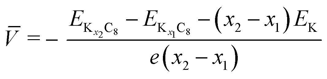
Fig. 1a and b display the galvanostatic charge–discharge curves and cycle stability of the graphite electrode with the PANa binder in K cells. The graphite–PANa electrode demonstrates a higher initial coulombic efficiency of 88% compared to the PVdF case (ca. 60%) and excellent long–term cycle stability with no capacity decay over 300 cycles11,13 (see the comparison in Fig. S6†). When PANa is used as a binder, the deposition of potassium alkyl carbonate-like species on the graphite surface is suppressed compared to the PVdF binder from HAXPES data (Fig. S7†). Compared to the PVdF case (Fig. S4†), an obvious influence is not found for the PANa content dependence (see Fig. S8†). Furthermore, when the PANa binder is used, the influence of different electrolyte salts of KFSA, KTFSA, and KPF6 appears to be insignificant (Fig. S9†). We note that a solution of 1.0 mol dm−3 KFSA/EC:DEC still offers higher initial coulombic efficiency and cycle stability compared to 0.8 mol dm−3 KPF6/EC:DEC.25 Additionally, the influence of EC-based binary solvents of EC:DEC, EC:DMC, and EC:PC on the reversibility is negligible for the PANa electrode during 100 cycles as confirmed by Fig. S10,† but 1.0 mol dm−3 KFSA/PC results in continuous electrolyte decomposition at 0.7 V vs. K (equal to 0.8 V vs. Li), which is likely due to co-intercalation of PC-solvated K+ ions and/or dissolution of SEI components, leading to graphite exfoliation and electrolyte decomposition24 similar to a Li|LiClO4-PC|graphite cell.30–32 Thus, we selected an electrolyte of 1.0 mol dm−3 KFSA/EC:DEC for the subsequent studies. Even at a high current rate of 1C (= 279 mA g−1), the graphite electrode exhibits quite stable reversible capacities with high coulombic efficiency over 300 cycles in a three-electrode K‖graphite cell (see Fig. S11†).33
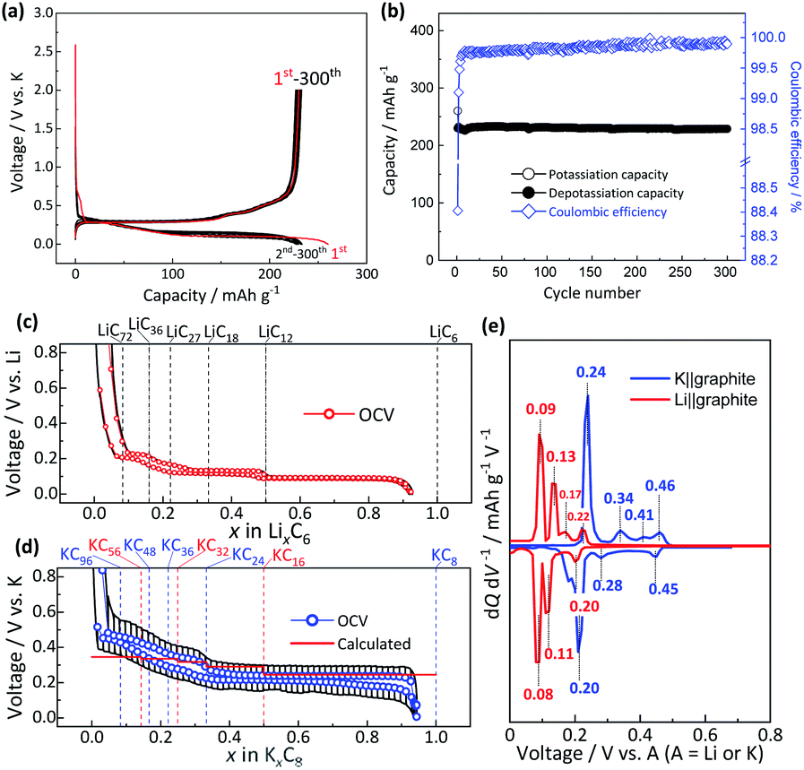 | ||
| Fig. 1 (a) Galvanostatic charge–discharge curves and (b) long-term cycling stability of the graphite electrode with the PANa binder in a K cell. OCV profiles of the graphite electrode in a (c) Li cell and (d) K cell at C/30 rate after the 2nd galvanostatic charge–discharge cycle. The calculated profiles of KxC8 (red solid line) are shown as the inset in panel ‘d’. (e) dQ/dV curves of the OCV plots of Li (red solid lines) and K (blue solid lines) cells. | ||
By using the three-electrode cell and the composite electrode of 3 μm graphite particles containing 10 wt% PANa binder, we further confirmed the good rate performance of the K‖graphite cell. Charge–discharge rate capability of Li and K cells was examined and compared (see Fig. S12†), and the K‖graphite cell demonstrates better rate performance than the Li cell owing to the larger potential margin between the charging plateau potential and the metal-plating potential. When we fixed the charging (intercalation) rate to 25 mA g−1 and varied the discharging (deintercalation) rate of the Li and K cells, both the cells demonstrate comparable rate capability up to ca. 100C whereas larger polarization is observed for the K cell (Fig. S13†). The polarization in the Li cell depends on the lithium concentration in graphite, but that in the K cell simply and linearly increases with the current values applied to the K cell. This result might represent larger resistance at the electrode/electrolyte interface rather than K+ diffusion in K-GICs. Surface and charge transfer resistances in a K‖graphite cell are often higher than those of the Li cell.34 Looking back at the influence of electrolyte and additive development on improving kinetics of Li-ion and Na-ion chemistry,35–37 future development of electrolyte and additives for K-ion batteries is rationally predicted to enhance the kinetics of the potassium intercalation process especially at the interface of a graphite electrode, which is ongoing in our laboratory.
Fig. 1c and d display the OCV profiles as a function of the intercalant concentration for the graphite electrodes in coin-type Li and K cells measured at the 6th cycle at 25 °C. The intercalant concentrations of Li and K, which were calculated from the charge passed, nearly reach x ≈ 1 in LixC6 and KxC8, respectively, at the end of the charging (intercalation) process while the values reversibly become almost zero at the end of the discharging (deintercalation) process. These results indicate the successful optimization of the electrode and appropriate selection of electrolyte components for the sufficient passivation of graphite. Actually, natural graphite used in this study has high crystallinity38 and exhibits excellent reversibility of the lithium and potassium intercalation reactions without apparent electrolyte decomposition owing to formation of a suitable SEI on the graphite surface. The Li cell shows several distinctive plateaus related to staging reactions, and the formula of LixC6, which can be described as LiC6/x at the end of each voltage plateau corresponds to LiC12, LiC18, LiC27, LiC36, and LiC72 as guided by dotted lines in Fig. 1c, whose compositions are well consistent with those reported previously.14,15,39,40 The OCV curve confirms the reversible feature, but a little voltage hysteresis between lithium intercalation and deintercalation processes is also observed in the limited compositional range of 1/6 ≤ x ≤ 1/3 in LixC6 similar to data in previous literature.15,41 On the other hand, the K cell also exhibits several voltage plateaus, but these are with vague voltage-changes especially in the low K amount region (ca. x < 0.33 in KxC8). As seen in Fig. 1d, the formula of K-GICs KxC8, which can be also described as KC8/x, at the end of each plateau is close to KC24, KC36, KC48, and KC96, of which compositions are in agreement with those of chemically synthesized K-GICs.42 A little voltage hysteresis is also observed in 1/6 ≤ x ≤ 1/3 in KxC8. The differential curves of the OCV profiles in Fig. 1e obviously display reduction and oxidation peaks, whose voltage values are consistent with those in the literature.14,15,43 In both Li and K cells, all the peaks are attributed to redox couples except for the oxidation peaks at 0.17 V and 0.41 V in Li and K cells, respectively, which correspond to the voltage hysteresis between intercalation and deintercalation processes.
To understand the theoretically and thermodynamically stable phases of K-GICs and compare the calculated voltage curve to the experimental ones, we performed DFT calculations on K-GICs. Fundamentally, graphite is composed of stacked graphene layers where the carbon atoms are planarly bonded with sp2 hybrid bonds in a honeycomb six-ring configuration. The graphene layers are bound by weak van der Waals interactions and are stacked in an ABAB sequence along the c-axis with an interlayer distance of 3.354 Å as shown in Fig. 2a and b. When alkali metal ions are intercalated into the interlayer space in graphite to form stage n GICs, the stacking sequence of the graphene layers changes into A|A, where the vertical bar denotes an intercalated layer and a letter refers to graphite layers.16 Stage-1 GICs usually have two dimensional (2D) in-plane orderings of the guest atoms in the interlayers. Stage-1 LiC6 has the 2D in-plane unit cell of LiC6 with the  superlattice with the stacking sequence of AαAαAα in the temperature range of T < 715 K44 (Fig. 2c and d). On the other hand, stage-1 K-GIC, KC8, has the in-plane unit cell of KC8 with the p(2 × 2)R0° superlattice and a three dimensional (3D) stacking sequence of AαAβAγAδ below 610 K (ref. 45) as shown in Fig. 2e and f.8,46 The in-plane and interplanar (stacking) orderings are known to be dependent on the in-plane density of intercalant ions.42 Thus, we considered six types of in-plane unit cells with KCm compositions; i.e. KC8, KC12, KC14, KC16, KC18, and KC24 (Fig. 2g) and several types of stacking sequences such as AAαAAα and ABβ′BAα (Table S1†). When we considered the stacking sequences including three types of graphene layers, A, B, and C types, the energies of AB|BA|AB| and AB|BC|CA| or ABA|ABA| and ABA|ACA| stacking sequences are expected to be close because the relative positional relationship between the two graphene layers, AB, BC, and CA types, is the same. Combining the in-plane unit cells and stacking sequences mentioned above, 30 different structures of KxC8, corresponding to stage-n KCm×n, are obtained, and their formation energies were calculated as plotted in Fig. 2h. From the structures having the lowest formation energies in the convex hull, DFT calculations predict stable staging structures (see their in-plane structures and stacking sequences in Table S2†) and the phase evolution sequence upon potassium intercalation as follows; graphite → stage 4 (KC56 and KC32) → stage 3 (KC24) → stage 2 (KC16) → stage 1 (KC8). Based on the calculation results, the average voltage between the compositions, x1 and x2, is computed as
 | (1) |
 and
and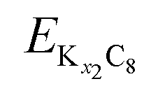 are the energies of Kx1C8 and Kx2C8, respectively, EK is the energy of metallic potassium, and e is the charge of an electron. A red solid line in Fig. 1d presents the calculated voltage profiles for the stable structures of KxC8 as a comparison with experimental voltage curves. The calculated voltage profile agrees with the measured OCV curves. The fact suggests that stage-2 KC16 is more stable than stage-2 KC24 and is expected to be formed during potassium (de)intercalation. The stable structure of stage-2 KC16 is slightly different from that in Luo's results10 and is rather similar to Lenchuk's ones47 (see Table S3†). Consequently, our computational results similarly predict thermodynamically stable formation of stage-2 KC16.
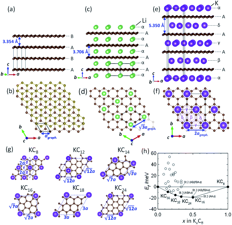 | ||
Fig. 2 (a, c and e) Schematic illustrations of crystal structures and (b, d and f) projected in-plane structures along the c-axis for (a and b) graphite, (c and d) stage-1 LiC6, and (e and f) stage-1 KC8. (g) In-plane unit cells for 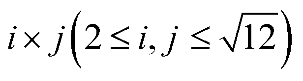 superlattices for which the carbon atom amount per potassium atom is denoted as labeled KCm compositions. (h) Formation energies Eform of stage-n K-GICs as a function of total potassium concentration x in KxC8 which can be described as KC8/x. superlattices for which the carbon atom amount per potassium atom is denoted as labeled KCm compositions. (h) Formation energies Eform of stage-n K-GICs as a function of total potassium concentration x in KxC8 which can be described as KC8/x. | ||
Operando XRD
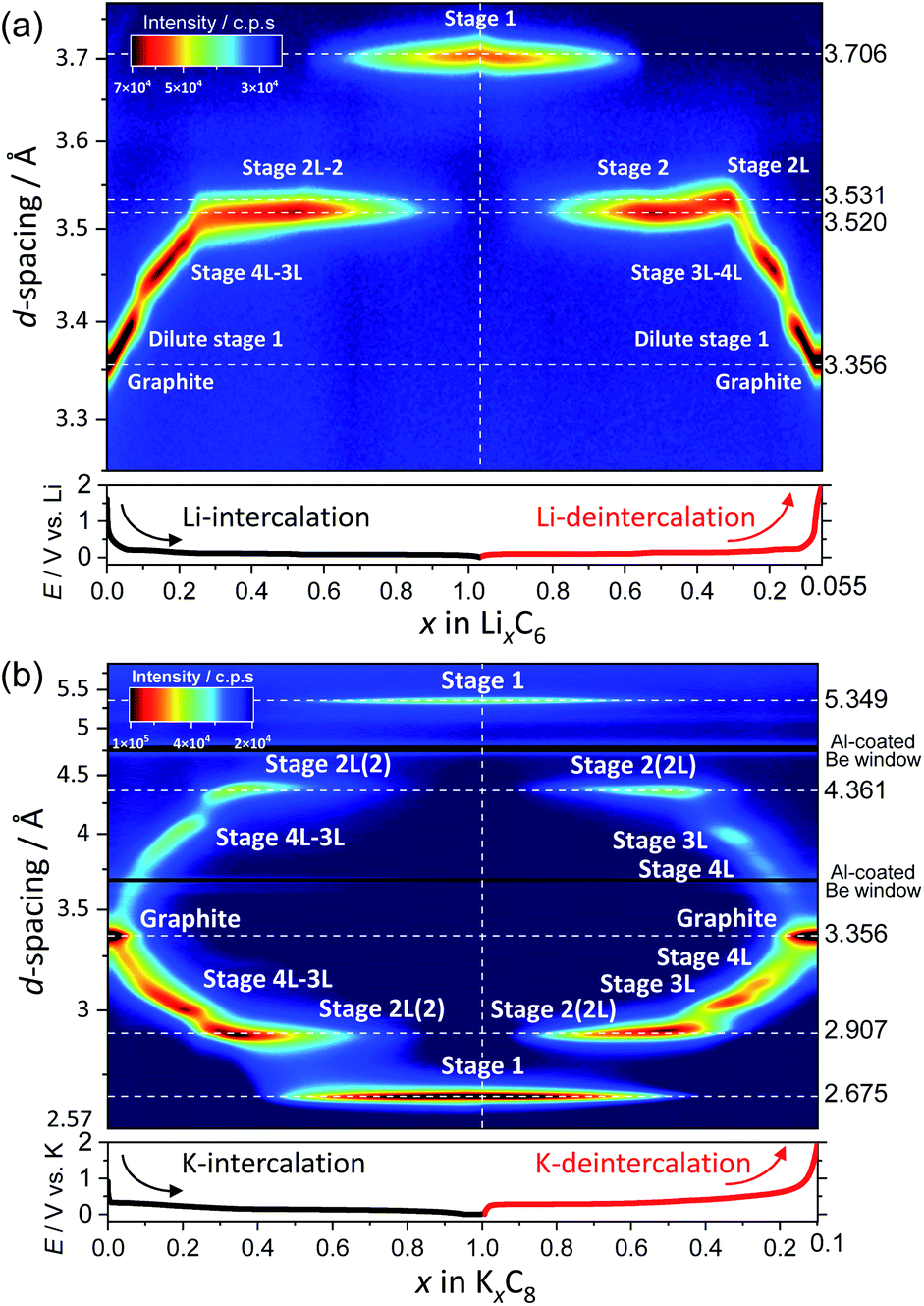
To elucidate the phase evolution behaviors of graphite, operando XRD was conducted for the Li‖graphite and K‖graphite cells during galvanostatic charge and discharge at the third cycle (to ensure SEI formation) at a quite slow rate of C/40 for Li and C/30 for K systems. Fig. 3a and b show the operando XRD patterns of graphite electrodes in a Li cell and a K one, respectively; an enlarged view for the Li cell is shown in Fig. S14.† Due to flake-like shape of graphite particles (Fig. S7†) and preferred orientation, only 00l Bragg diffraction peaks are observed. | ||
| Fig. 3 Operando XRD patterns of graphite electrodes in (a and c) Li‖graphite and (b and d) K‖graphite cells at a current density of 9.3 mA g−1: in the diffraction angle regions of (a and b) 15–35°, (c) 25–27.5°, and (d) 25–29.5°. The CV mode at 2 mV for 5 h was employed only in the K system at the end of a K-intercalation process. | ||
The 00l reflection at the diffraction angle, 2θ of 24°–26° for the Li system and 20°–26° for the K system gives the repeat distance Ic corresponding to the minimum distance between intercalant layers.42 Considering the structure of a stage n compound, Ic can be calculated with the following equation assuming that the distance of the empty interlayer spacing (3.35 Å)48 and that of the interlayer spacing filled with Li (3.706 Å) as in LiC6 (ref. 5) or K (5.35 Å) as in KC8 (ref. 16) remain constant across different stages.
| Ic = (n − 1)d0 + di, | (2) |
 | (3) |
The calculated d00n values are shown in Table S3† and these were compared to the observed d-spacings of the 00n reflections to identify the stage number at each state-of-charge. From the indexation of the 00n reflection with the d00n value in the d-spacing, the d-spacing of the  reflection is given by the following equation:
 | (4) |
In the KCx system, the reflections at 20°–26° and 26°–34° correspond to 00n and  , respectively, in this hypothetical structure, confirming the presence of stage-ordered potassium-intercalated graphite. We note that indexation may differ for the structures with an interlayer ordering along the stacking direction, as in stage 1 KC8 where the c unit–cell parameter is quadrupled and potassium layers have a specific stacking ordering with the AαAβAγAδ sequence8; the indexation based on the KC8 structure was used in this case instead.
In the Li case, a 002 Bragg diffraction peak of graphite located at a 2θ of 26.55° shifts toward a lower diffraction angle during intercalation and shifts back to a high angle during deintercalation, which indicates an enlarged average interlayer distance by lithium intercalation into the graphite host.5 The peak shift is not fully continuous, and multiple and staging phase-transitions are observed from graphite to LiC6 during an intercalation process, and a deintercalation process from LiC6 to graphite is accompanied with slight structural change hysteresis. The structural changes of graphite during lithium intercalation occur in the transition sequence: graphite → dilute stage 1 → stage 4L–3L → (stage 2L →) stage 2 (LiC12) → stage 1 (LiC6). During the lithium deintercalation process, the phase evolution proceeds in the sequence; stage 1 (LiC6) → stage 2 (LiC12) → stage 2L → stage 4L–3L → dilute stage 1 → graphite, where L refers to the “liquid-like” distribution of lithium atoms in the interlayer space. For instance, dilute stage-2 LiC18 has a lower in-plane lithium density of a LiC9 in-plane unit than a LiC6 unit in stage-2 LiC12 and has a “liquid-like” in-plane distribution of lithium atoms at room temperature.39 Thus, a primitive in-plane unit of p(1 × 1)R0° is often employed as an averaged in-plane unit for the structural refinement of stage 2L50,51 without consideration of a possible short-range ordering of lithium atoms although stage-2L LiC18 might have a “liquid-like” local in-plane ordering as a p(3 × 3)R0° superlattice which was proposed with XRD data52 and predicted by DFT calculations.53 Despite the “liquid-like” in-plane distribution of lithium atoms, stage-2L LiC18 is known to have an interplanar ordering of the AB|BA| stacking sequence at room temperature.39,54 Furthermore, stage-2L LiC18 is a metastable phase, of which the pure phase is prepared by an electrochemical method,39,52 and transforms into dense stage-2 LiC12 and stage-3 LiC18 below ca. 290 K.55 Thus, the operation temperature for the Li cell tests is an important factor, and Dahn and coworkers predicted the disappearance of the stage 2L phase below 10 °C based on the voltage curves.14 Similar to previous literature,51,56,57 a Bragg diffraction peak of stage 2L is clearly observed at a 2θ of 25.2° upon the lithium deintercalation process at room temperature in Fig. 3a. Although the stage 2L might be formed during the Li-intercalation process, distinct Bragg peaks for this phase are not obviously observed, which is consistent with the previous results of operando neutron diffraction (ND) measurements.51,56,57
For the K cell in Fig. 3b, the 002 Bragg diffraction peak of graphite first splits into two peaks, and they shift gradually to lower and higher angles upon potassium intercalation and reversibly go back to the initial position during the deintercalation process, indicating that a reversible change in average interlayer distances increased/decreased by potassium intercalation/deintercalation, respectively. Despite 1.6 times lattice expansion of graphite by complete K-intercalation and formation of stage-1 KC8, the reversible potassium intercalation/deintercalation behaviors are confirmed with obvious multiple staging reactions.
A remarkable difference in phase transitions for Li and K systems is found at the early intercalation process. The magnified operando XRD patterns of Li and K cells in the high stage regions are shown in Fig. 3c and d, respectively. In the Li system, the graphite 002 peak shifts continuously to a lower angle without a significant change in the peak width as lithium intercalates into graphite. This indicates expansion of the interstitial space with homogeneously increasing in-plane lithium concentration (see Fig. S15a†). Thus, this phase is called dilute stage 1 (ref. 14) having a “gas-like” in-plane lithium distribution,58 because the low lithium concentration of the intercalant layer has a negligibly weak interplanar interaction, and the graphite host retains the ABAB stacking manner without gliding of graphene sheets.58 On the other hand, in the K cell, the graphite 002 peak remains at the initial peak position, but its intensity rapidly decreases as potassium intercalation proceeds, and a pretty broad peak simultaneously appears with peak shift toward a higher angle as shown in Fig. 3d. The broadening of 00l diffraction corresponds to reduction of coherence along the stacking axis, indicating increased stacking disorder51 as drawn in the schematic model in Fig. S15b.† It is most likely that potassium atoms randomly and heterogeneously intercalate into the graphite host to form locally staged K-GICs layers,59 resulting in the stage disordering along the c axis in the high stage region (n > 8) at room temperature. This transition behavior is consistent with that in the chemically prepared K-GICs.60 Furthermore, the staging difference can be explained by Liu's61 and Lenchuk's47 computational results. In both calculations, stabilizing GICs mainly require large negative binding energies contributed from the electrostatic and van der Waals interactions between layers and the ionization and decohesion energies of alkali metals. The binding energy is generally high when the concentration of intercalant ions is high. In contrast to the binding energy, the energy cost required to change the stacking of graphite layers from AB to AA and expand the interlayer spacing (so called graphite-deformation energy) is positive and increases with increasing the atomic size of the intercalant ions.47 Although the graphite-deformation energies of Li-GICs are smaller than those of K-GICs due to the smaller size of the lithium ion, energy contribution from the AB–AA transition is large because Li-GICs have a narrower interlayer spacing and stronger van der Waals interactions between the graphene layers as well as stronger electrostatic and covalent interactions between alkali metal ions and the nearest graphene layers. The low concentration of Li intercalant does not generate enough binding energy to overcome the AB–AA transition, forming the dilute stage-1 Li-GIC with ABAB stacking remaining. On the other hand, in K-GICs, energy contribution from the AB–AA transition is relatively small, and the expansion of interslab spacing contributes to the deformation energy predominantly.47 The binding energy is also large in K-GICs and overcomes the graphite-deformation energy. However, the interlayer interactions in K-GICs are weaker than those in Li-GICs and further weaker in lower potassium concentrations. These factors probably lead to a disordered stacking transition of the graphite layers as the disorderedly stacked high-stage K-GIC is experimentally observed at room temperature in this study.
The operation temperature is an important factor in staging evolution of GICs as mentioned above for the stability of stage-2L LiC18. In this study, we measured an OCV curve for a K‖graphite cell at 0 °C only in the potassium deintercalation process. However, no significant difference in the OCV from that examined at room temperature is confirmed from the differential curve as shown in Fig. S16.† This is because stage n K-GICs (n ≥ 2) have a “liquid-like” in-plane structure without strong interplanar interactions with the facing graphene layers above 250 K.62,63 Furthermore, the dilute stage-2L KC24 is stable in the wide temperature range and represents no phase-separation reaction at 12–300 K (ref. 62 and 64) unlike the phase transition of the dilute stage-2L LiC18 into stage-2 LiC12 and -3 LiC18 in < ca. 290 K.14,55
The continuous and discrete changes in d-spacings as well as phase evolutions are effectively visualized in the color contour plots with the d-spacing and diffraction intensity for both the Li and K cells as shown in Fig. 4a and b where the d values were converted from the diffraction angles 2θ in Fig. 3a and b, respectively.
 | ||
| Fig. 4 Contour plots of the operando XRD patterns of graphite electrodes in (a) Li and (b) K cells at a current density of 9.3 mA g−1. | ||
In the Li cell, the d-spacing corresponding to dilute stage 1 and stage 4L–3L continuously changes during charge and discharge. In contrast to continuous variations, a constant d-spacing is observed for stage 2 (3.52 Å) and stage 1 (3.71 Å) Li-GICs as a two-phase reaction corresponding to the flat voltage plateau is observed in the charge–discharge curves in Fig. 1c. In the deintercalation process, a wider d-spacing of stage 2L (3.53 Å) than that of stage 2 (3.52 Å) is also consistent with those in the literature.39,51,56,57
On the other hand, the contour plots for the K cell (Fig. 4b) represent weak and broad diffraction peaks during the early intercalation process until the formation of stage 3L, which is indicative of the formation of a disorderly stacked high stage. Without clear observation of stage 4L in the contour plots, the d-spacing corresponding to stage 3L appears in the relatively early intercalation process and continuously changes like stage 4L–3L in Li-GICs. Upon the further potassium intercalation, a constant d-spacing for stage 2 (including 2L) (4.36 Å) and 1 (5.35 Å) appears along with the increase in (stage 1)/(stage 2) peak ratio, suggesting a two-phase reaction similar to the Li system. These results agree with a flat voltage plateau in 0.5 ≤ x ≤ 1 in KxC8 (Fig. 1d). In contrast to the intercalation process, the d-spacing corresponding to stage 4L is clearly observed and isolated from that of stage 3L during the subsequent deintercalation process.
To understand more details of the phase evolution, we further analyzed the diffraction patterns by peak fitting with the pseudo-Voigt function (see the selected fitting results in Fig. S17†). The peak fitting enables precise determination of the d-spacing and the peak height and width of each phase component. Fig. 5 shows variation in the peak height and full width half maximum (FWHM) of d00l diffraction as a function of x in LixC6 and KxC8. In the Li system (Fig. 5a, c, and e), stage-1 LiC6, -2 LiC12, and -2L LiC18 phases are found to have averaged specific interlayer distances of 3.71 Å, 3.52 Å, and 3.53 Å, respectively. The different interlayer distances between stage 2 and 2L indicate different in-plane lithium densities sandwiched between neighbor graphene sheets.39 In the other stages, d00l values continuously vary as a function of lithium concentration, showing a variable in-plane lithium density although typical compositions and structures of some stages such as stage-3L LiC29-40 were reported.49 Consequently, lithium intercalation proceeds in the following manner; graphite is transformed into dilute stage 1 in x ≤ 0.1 in LixC6 → stage 4L–3L in 0.1 ≤ x ≤ 0.3 → stage 2 (including 2L) in 0.2 ≤ x ≤ 0.5 → stage 2 + stage 1 in 0.5 < x < 1.0 → stage 1 LiC6. During following lithium deintercalation from LiC6, phase evolution proceeds in the following sequence; stage-1 LiC6 → stage 1 + stage 2 in 0.5 < x < 1.0 → stage-2 LiC12 → stage 2 + stage 2L in 0.3 < x < 0.5 → stage-2L LiC18 → stage 2L + stage 3L in 0.17 ≤ x < 0.3 → stage-3L–4L LiC36 → dilute stage 1 in 0.1 < x < 0.16 → graphite.
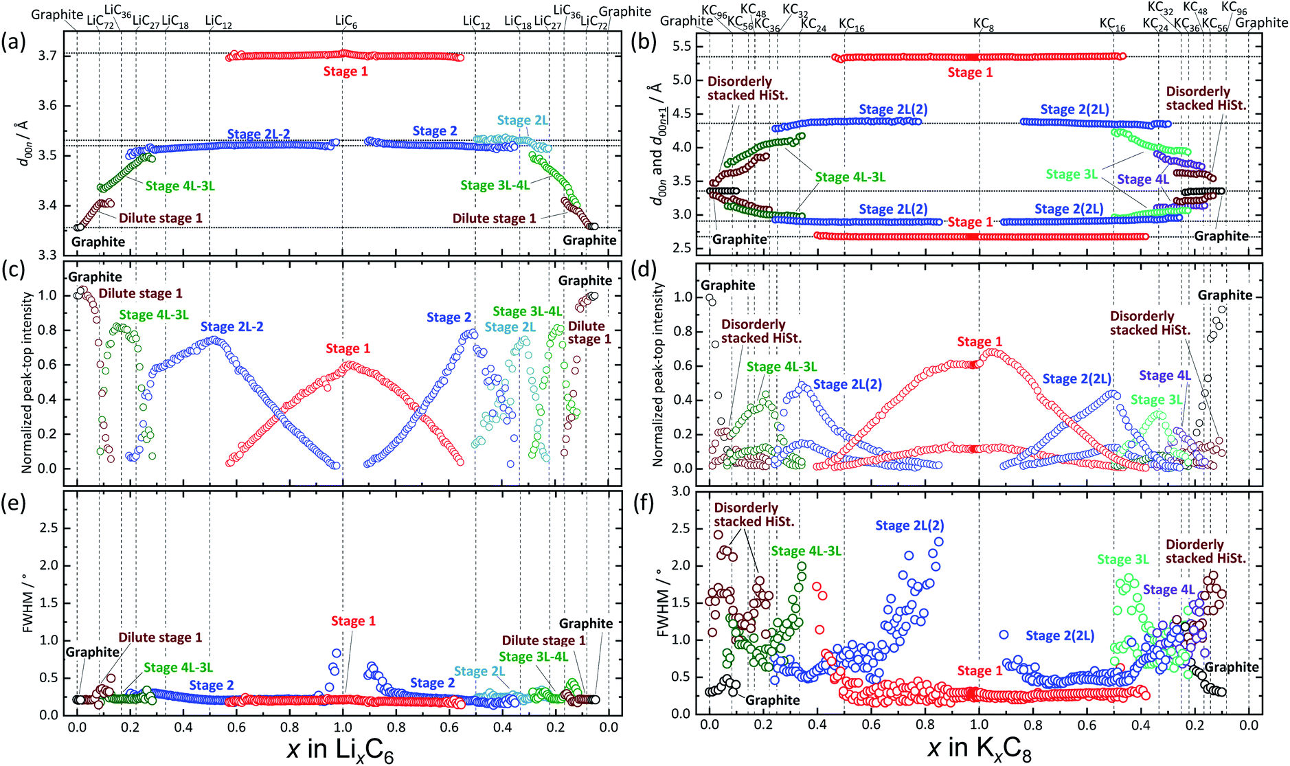 | ||
| Fig. 5 Variation of (a and b) d00l, (c and d) peak-top intensity, and (e and f) FWHM as a function of x amounts of (a, c and e) LixC6 and (b, d and f) KxC8. | ||
It should be noted that peak-top intensity of stage 2 in the lithium intercalation process has two inflection points at LiC18 and LiC12 as seen in Fig. 5c. The fact might represent formation of stage 2L during the lithium intercalation process as a phase mixture between stage 2L and stage 2 as suggested by Ohzuku15 and Billaud.49
Similar to the Li system, we discuss the K system (Fig. 5b, d, and f) with consideration of continuous and discrete changes in the potassium concentration in graphite. In previous literature, chemically prepared K-GIC phases and the staging phase evolution are as follows: stage-1 KC8, stage-2L KC24 and KC28,65 stage-3L KC36, stage-4L KC48, and stage-5L KC60.8 From the operando XRD data of Fig. 5d, electrochemical potassium intercalation is found to proceed in the transition sequence of graphite → graphite + disorderly stacked high stage in x < 0.07 in KxC8 → the high stage + stage 4L–3L in 0.07 ≤ x < 0.22 → stage 4L–3L at x ∼0.22 → stage 4L–3L + stage 2L in 0.22 < x < 0.33 → stage 2L in 0.33 ≤ x ≤ 0.38 → stage 2L + stage 1 in 0.38 < x ≤ 0.83 → stage-1 KC8. In the potassium deintercalation process, the phase transitions proceed through the reversal process from stage-1 KC8 to graphite. However, the potassium concentration range for each stage and the phase transition between stage 3L and 4L are different from those in the intercalation process, which is reasonably related to the reaction and voltage hysteresis between charge and discharge. The transition sequence and compositional ranges in the potassium deintercalation are as follows: stage-1 KC8 → stage 1 + stage 2(L) in 0.48 < x < 0.90 in KxC8 → stage 2(L) at x ∼0.48 → stage 2(L) + stage 3L in 0.31 < x < 0.48 → stage 3L x ∼0.31 → stage 3L + stage 4L 0.20 < x < 0.31 → stage 4L + disorderly stacked high stage in 0.13 < x < 0.20 → disorderly stacked high stage + graphite in 0.05 < x < 0.13 → graphite. Interestingly, obvious peak separation among stage-3L, -4L, and the high stage is found in the deintercalation process, while the continuous variation of the interlayer distance from the disordered high stage to the stage 3L is observed in the intercalation process as shown in Fig. 5d.
The transition hysteresis between the potassium intercalation and deintercalation is clearly found in the offset-free operando XRD patterns (see Fig. S18†). In the deintercalation, three inflection points in intensities are observed at 2θ values of 29.40°, 28.68°, and 27.86°, and the reflections can be assigned to stage 3L, 4L, and the high stage, respectively. Reduction and gain of the intensities between the phases are indicative of two-phase reactions. On the other hand, on intercalation, the broad peak region at 2θ values of 26.56°–29.76° can be divided into mainly three regions; a two-phase region of graphite and high-stage at 26.56°–28°, a two-phase region of high-stage and stage 4L–3L at 28°–29.08°, and a single-phase region of stage 4L–3L at 29.08°–29.76°. In the former two two-phase regions of 26.56°–28° and 28°–29.08°, reduction and gain in intensity are found, and a continuous peak-shift and monotonous intensity gain are seen in the latter region of 29.08°–29.76°. This hysteresis of the phase evolutions is consistent with the voltage hysteresis in the charge and discharge profiles around 0.41 V in Fig. 1d and e.
Furthermore, the maximum peak-top intensity of stage 2(L) is obtained at x = ca. 0.5 in KxC8 upon the potassium deintercalation process (Fig. 5d), indicating the formation of stage-2 KC16. In contrast, the maximum intensity of stage 2(L) in the intercalation process is located at x = 0.33 in KxC8 corresponding to the KC24 composition. As mentioned in a previous report,51 lithium intercalation into a stage-3 phase produces a stage-2 phase having stacking faults and/or modulated domains between the stage-3 and -2 Li-GICs whereas almost fault-free stage-2 and -2L Li-GICs form during the reversal deintercalation process. The detailed phase transition mechanism related to crystallite domains is discussed in the later section.
It is worth mentioning that another notable feature of the K-GIC staging transition appears in the FWHM plots of Fig. 5f which is distinctly different from that of the Li-GIC plots in Fig. 5e. In the Li cell, larger values of the FWHM are observed only for the diffraction of stage-2 around x = ca. 0.9 in LixC6. Considering Scherrer's equation,66 this broadening should originate from nanocrystal domains just after nucleation or before the disappearance of the stage-2 phase at compositions close to the terminal phases in the two-phase reaction of stage-1 and -2. Additionally, slight but certainly large FWHM values are seen at the boundary compositions for dilute stage 1/stage 4L–3L and stage 4L–3L/stage 2 as previously reported.51
In contrast to the Li system, the K system exhibits much larger FWHM values and pronounced variation as seen in Fig. 5e and f. This indicates drastic reduction in the stacking coherence of graphene and potassium layers along the c axis, probably related to variation of long-range ordering including stacking faults and micro-strain at the phase boundary between the K-GICs phases. Owing to a larger atomic size and a lower Lewis acidity of the potassium ion compared to the lithium one, in-plane distribution and concentration of alkali metal ions as well as stacking manners of graphene layers in the graphite host are different between K-GICs and Li-GICs.
Structures and the intercalation mechanism
From the above discussion including the stacking faults and/or modulated domains as well as in-plane and interlayer orderings of Li- and K-GICs, we herein propose structural evolution of Li- and K-intercalated graphite schematically shown in Fig. 6.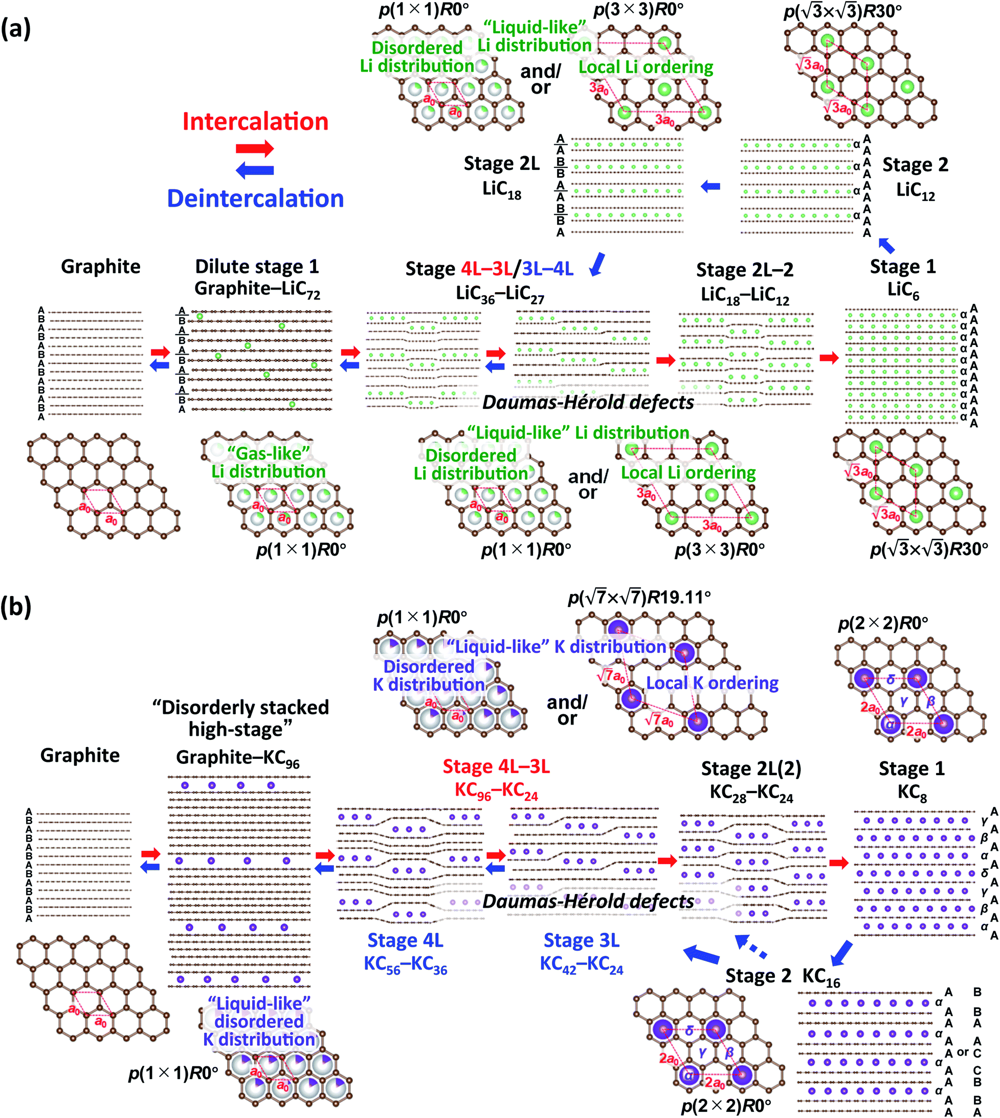 | ||
| Fig. 6 Schematic illustrations of the plausible phase evolution models for electrochemical (a) Li and (b) K (de)intercalation into graphite. | ||
In the Li system, at the beginning of lithium intercalation into graphite, “gas-like” dilute stage 1 is formed with retaining the ABAB-stacked graphite host structure with approximate compositions of graphite–LiC72. When the in-plane lithium density with the same total composition as in the dilute stage-1 reaches LiC72, further lithium intercalation produces A|A stacking around lithium by gliding the graphene layers to form stage 4L with ABAB|BABA| stacking51 and then stage 3L with ABA|ACA| stacking.49 These phases, however, usually have stacking faults in the structures at room temperature49,67 because of the “liquid-like” in-plane lithium distribution and the weak interaction of the intercalant lithium ions with neighbor graphene layers at a low lithium concentration.
Stage-4L is generated as a two-phase reaction with the dilute stage-1, and its initial composition is close to LiC36 in total. Then, a continuous phase transition occurs between stage 4L and 3L according to the operando XRD patterns in Fig. 4a and 5a, c and e, which is consistent with those reported in the literature.14,51,57 In terms of a structural change mechanism, the stage transition between the even and odd n indices of stage-n GICs cannot be explained by using a typical flat layered model (so called Rüdorff–Hofmann model68) but can be explained by a domain model with Daumas–Hérold defects,69 which was proposed by N. Daumas and A. Hérold. As shown in Fig. 6a, stage 4L and 3L domains coexist and are separated by a Daumas–Hérold type defect (so-called Daumas–Hérold wall) as a domain boundary. Thus, phase transition proceeds like a single-phase reaction via migration of the Daumas–Hérold defect boundary. As further lithium intercalation leads to reaching LiC36 in total composition, stage 2 domains are generated and co-exist with stage 4L–3L as well as the Daumas–Hérold defects. The stage-2 LiC12 has the 3D-ordered structure with the in-plane unit cell of LiC6 with the  superlattice similar to that of stage-1 LiC6 and the unique stacking sequence of AAαAAα below 500 K.5,54 In this staging region of LiC36–LiC18, dilute stage 2L having the “liquid-like” LiC9 in-plane unit could be co-generated with stage 2 at room temperature as previous operando X-ray and neutron diffraction data also proved the low but trace amount of the stage 2L phase during the intercalation process.14,51,70 In our operando XRD data in Fig. 5c and as mentioned above, two inflection points are observed at LiC18 and LiC12 in the peak-top intensities of the stage-2 phase. The former point probably corresponds to the maximum phase fraction of stage-2L. When the total composition reaches the later compositional point of LiC12 by further lithium intercalation, a single and 3D ordered phase of stage-2 LiC12 is expected to be obtained according to our operando data in Fig. 5c. However, on the basis of the analogy to the potassium intercalation and the differences between intercalation and deintercalation described in a later section, it is speculated that the LiC12 phase formed in the intercalation process has Daumas–Hérold defects that prevent the integration of the LiC12 domains.
Once stage-1 LiC6 with 3D AαAαAα stacking is formed by complete lithium filling, Daumas–Hérold defects disappear. So, the subsequent lithium deintercalation from stage-1 produces stage-2 having 3D AAαAAα stacking and no Daumas–Hérold defects principally. The formation of stage-2 LiC12 in a defect-free 3D ordering facilitates the transformation into dilute stage-2L LiC18 during the subsequent deintercalation process. Then, Daumas–Hérold defects are generated again in the phase transitions between stage 2L/3L–4L transition, and graphite with ABAB stacking is formed though dilute stage 1. The disappearance of the Daumas–Hérold defects explains the reaction hysteresis between intercalation and deintercalation. Unfortunately, observed peak broadening to support formation of the Daumas–Hérold defects is not clearly seen in our operando XRD data for Li-GICs due to measurement limit of our laboratory-scale XRD. Didier et al., however, recently reported operando ND data proving drastic changes in peak width attributed to the formation of Daumas–Hérold defects and their disappearance at the end of the intercalation process as well as reaction hysteresis between the intercalation and deintercalation.51 We employed this reaction model to the K-GIC system.
In the K system of Fig. 6b, at the beginning of the potassium intercalation process in the approximate composition range of graphite–KC96, graphite partially and gradually transforms into a disorderly stacked high stage accompanied by gliding of graphene layers to form A|A or B|B stacking unlike “gas-like” lattice formation of dilute stage-1 Li-GIC retaining the ABAB stacked graphite host structure as mentioned above in Fig. 3c and d. Although the structure of the disorderly stacked high stage is schematically illustrated as the Rüdorff–Hofmann model68 representing stacked empty and filled interlayers (Fig. 6), the Daumas–Hérold model with island domains might be suitable for depicting the high stage K-GIC structure. Due to intercalation of large potassium ions and formation of large interlayer spacings, significant coherency strain between the graphite and high stage K-GIC domains as well as a large in-plane size of graphite domains contribute to the random distribution of the stage domains as proposed by Safran.71
Further potassium intercalation into the high-stage K-GIC produces stage 4L–3L, and the two-phase reaction proceeds in the composition range of KC96-36 (see Fig. 5b, d, f, and S18†). Although the stage 4L–3L transition looks like a single-phase reaction during the potassium intercalation process and is a two-phase reaction during the deintercalation process as mentioned above, the stage 4L and -3L K-GICs are reported to have a “liquid-like” in-plane potassium distribution at room temperature63 similar to the stage n Li-GICs (n > 2). Furthermore, variable peak positions were reported for the in situ XRD patterns of stage-n K-GICs (n > 2) under chemical potassium vapor pressure.72 Thus, both the stage-4L and -3L phases are expected to have variable potassium concentration of the in-plane unit as plausible composition ranges are shown in Fig. 6b. Furthermore, despite the “liquid-like” in-plane potassium distribution at room temperature, an interplanar ordering (stacking ordering) for stage-n K-GICs (n ≥ 2) is known as follows:16,73
| |(AB)n/2|(BC)n/2|(CA)n/2| for even n, | (5) |
| |A(BA)(n−1)/2|A(CA)(n−1)/2| for odd n. | (6) |
The difference in stacking sequences between even- and odd-numbered stages requires the Daumas–Hérold defects as domain boundaries in staging evolution of K-GICs like the Li-GICs system. Thus, the stage 4L–3L transition proceeds via formation of multiple domains separated by Daumas–Hérold defects as shown in Fig. 6b even though the variation of intensities and peak-shift looks like a single-phase reaction in the operando XRD patterns (see Fig. S18†). When the potassium concentration increases and the total composition of K-GICs reaches KC36, the stage 2L (including stage 2) phase appears and coexists with stage 3L as a two-phase reaction in the compositional range of KC36–KC24 (Fig. 5d and f). The stage 3L–2L transition also requires Daumas–Hérold defects Fig. 6. The subsequently formed stage-2L K-GIC also retains the defects within the phase as the stage 2L phase exhibits quite broad and asymmetric diffraction peaks in Fig. 3b, 4b, and 5d. The broad and asymmetric peak profiles probably correspond to disordered staging domains including Daumas–Hérold defects and/or stacking faults. The asymmetric peak profile is also reported for Li-GICs during Li (de)intercalation, and structural models including stacking faults are proposed for stage-2 LiC12 (ref. 67) and stage-2L LiC18.51
A distinct asymmetric peak profile for the  reflections of stage 2 and stage 1 phases and a high intensity baseline between the peaks are observed during the intercalation process (see Fig. S19†). However, in the subsequent deintercalation process from stage-1 KC8, asymmetric peak-broadening is not obvious for both stage-1 and stage-2 peaks. The fact indicates that most of the Daumas–Hérold defects disappear by complete filling of potassium atoms and formation of a single phase of 3D-ordered stage-1 KC8 at the end of the intercalation process similar to Li-GICs in Fig. 6a. Stage-1 KC8 has the ordered KC8 in-plane unit of the p(2 × 2)R0° superlattice and would transform into stage-2 KC16 with retaining the in-plane ordering with the ordered KC8 unit65 as discussed in Fig. 5b, d, and f. Although the stacking sequence of stage-2 KC16 could not be determined due to too low intensities of hk0 Bragg reflections from the oriented graphite particles, our DFT calculations predict that the most stable stage-2 KC16 has AAαAAα stacking, which is consistent with the previous calculated results.10,47 However, the formation energy is found to be quite close to that of KC16 with ABβ′BAα stacking, and the energy difference is 1.54 meV (see Fig. 2h), indicating a possible mixture of AaαAAα and ABβ′BAα stacking sequences as stacking faults. Indeed, a slight but certain peak-shift is observed for stage-1 and -2(L) K-GICs in our operando XRD data even during the deintercalation process (see the operando XRD pattern enlarged regions for stage-2(L) and -1 without intensity offset in Fig. S20 and S21,† respectively, and those in Li-GICs as a reference in Fig. S22†). The peak-shift for stage-2(L) during the deintercalation process is smaller than that during the intercalation process (see Fig. S20†), indicating the lower degree of Daumas–Hérold defects during the deintercalation process.
Although the peak-shift or different peak-positions for stage-2(L) K-GICs were expected to originate from the transition between stage-2 KC16 and stage-2L KC∼24 phases as proposed by Liu,19 our calculated results predict negligibly small differences in peak position just by a Δ2θ value of 0.01° for both the 00n and  peaks (Ic = 8.748 Å, 2θ00n = 20.30°, and
  for KC16 and 8.744 Å, 20.31°, and 30.67° for KC24). The average interlayer distance of stage-2 KC16 is about the same as but slightly larger than that of stage-2 KC24, which is consistent with Liu's computational results.19 However, the simulated XRD pattern of stage-2 KC16 presents lower-angle 00l reflections than those of stage-2 KC24 and cannot explain the peak shift in the opposite direction of 00n and
  reflections for the stage-2(L) K-GICs in Fig. S20.† Interestingly, this is different from the stage-2 Li-GICs, in which only a lower-angle shift of 00l reflections is experimentally confirmed for the transition from stage-2 LiC12 to stage-2L LiC18 as a two-phase reaction.39,50,51 Since the FWHM of 003stage-2(L) reflection for stage-2(L) K-GIC becomes smaller through the peak shift from 30.84° to 30.66° during the potassium deintercalation process (see Fig. S20†), the peak-shift and -broadening are probably due to stacking faults such as unusual AB|BA|, AC|CA|, and BC|CB| sequences proposed for chemically prepared stage-2L KC∼24.73
Similar to the case of stage-2 K-GIC, stage-1 KC8 reflections show a slight peak shift and intensity-gain and -reduction at the beginning of the deintercalation process in our operando XRD data (Fig. S21†) as well as in the reported data.18,19 Such a phenomenon is also confirmed for stage-1 Li-GICs during the beginning of lithium deintercalation in Fig. 5a and S21† as well as in previous results.51,74 As variation of long-range ordering along the stacking direction was proposed for the stage-1 Li-GIC domain,51 formation of stacking faults is expected for the stage-1 K-GIC domain during potassium (de)intercalation similar to the above mentioned stage-2(L). Furthermore, stage-1 KC8 with AαAβAαAβ stacking was experimentally observed as an intermediate phase between the AαAβAγAδ stacked stage-1 KC8 and the AB|BC|CA| stacked stage-2L in the in situ high-temperature XRD patterns of K-GICs.75 Stacking faults in a potassium stacking sequence might contribute to the peak shift and intensity variation.
Although a slight peak shift and intensity change are found for stage-2(L) and -1 as mentioned above, a distinct difference between potassium intercalation and deintercalation processes is confirmed in FWHM values (Fig. 5). The FWHM values of stage-2(L) during potassium deintercalation are smaller than those during intercalation. The fact reveals no or less Daumas–Hérold defects in the 2D or 3D ordered stage-2 KC16 phase during the potassium deintercalation process like in a 3D ordered stage-2 LiC12 during a lithium deintercalation process.51 Furthermore, the maximum peak-top intensity is obtained at the KC16 composition during the defect-less early deintercalation process (Fig. 5d), suggesting electrochemical formation of thermodynamically stable stage-2 KC16 at room temperature.
The subsequent potassium deintercalation from stage-2 KC16 causes critical phase transitions between even and odd indices of stage-n; i.e. stage 2 to stage 3L, again. Daumas–Hérold defects appear between the stage domains as confirmed by large FWHM values in Fig. 5f. Formation of dilute stage-2L KC24–KC28 was expected from the literature on chemically prepared phases,65 but the peak intensity of the stage 2 phase has an inflection point at the KC16 composition and linearly decreases by potassium deintercalation (Fig. 5d), resulting in the formation of stage-3L KC24 as a two-phasic reaction. This transition sequence is consistent with Luo's10 and our DFT calculations results. Further potassium deintercalation from stage-3L KC24 leads to the transition from stage 3L to 4L with Daumas–Hérold defects. Although these phases have a “liquid-like” in-plane potassium distribution, a commensurate  superlattice and/or incommensurate in-plane structures, depending on the in-plane potassium densities, might be locally formed (Fig. 6b) as reported for chemically prepared K-GICs at low temperature.62,63,76–81 The presence of stage 4L is evident in the operando XRD patterns in which the diffraction peaks were deconvoluted into stage 3L and 4L during the deintercalation process but not during the intercalation process (see Fig. S17†). During the potassium intercalation process, stage-4L domains are formed inside the dilute stage 1 phase, which is island-domain-free and has large crystallites of the same size as graphite. On the other hand, during the deintercalation process, the pre-formed stage 3L phase has Daumas–Hérold type island domains with smaller in-plane crystallite size. This might enhance the kinetics of the stage-3L to -4L transition during the deintercalation process. Finally, highly crystalline graphite is formed back through the formation of disorderly stacked high stage K-GICs as observed during the potassium intercalation process and discussed in Fig. 3d.
Electrochemical intercalation of the large ionic radius and low Lewis acidity potassium ion provides significantly different interlayer distances of graphene layers between empty and intercalated cases. Electrochemically formed K-GICs have unique characteristics such as staging disorder at the high stage, obvious reaction hysteresis during charge–discharge related to the phase-integration/-isolation of stage 4L with/from a disorderly stacked high stage, strong evidence of Daumas–Hérold defects as a domain boundary between the even- and odd-index of stage-n K-GICs domains, and formation of stage-2 KC16, which are successfully confirmed by operando XRD during potassium (de)intercalation into graphite and by DFT calculations in comparison with those of Li-GICs. Indeed, our operando XRD measurements were carried out under current flow (closed circuit) conditions, therefore, the phase evolution observed here is not under ideal equilibrium conditions. Also, the phase evolution of graphite during electrochemical intercalation would be influenced by materials and conditions, as discussed for the Li-GIC data51 with factors such as graphite crystallinity,38 electrode compression,82 the current rate,57 and temperature.14 In this study, the phase evolution for K-GICs as well as Li-GICs was investigated by using highly crystalline natural graphite and comprehensive analysis such as electrochemical methods, operando XRD at very slow current rates, and DFT calculations with consideration of the previous reports on chemically prepared K-GICs. Our findings on electrochemical potassium intercalation and corresponding phase evolutions are expected to contribute to the fundamental understanding of GICs as well as the further development of high-energy K-ion batteries.
Conclusions
The influence of the graphite particle size, binder, and electrolyte salts and solvents on the electrochemical potassium intercalation properties is systematically examined in non-aqueous K cells. Because we optimized the graphite electrode and electrolyte for higher reversibility intercalation, we successfully studied structural evolutions of graphite and K-GICs during electrochemical potassium intercalation into graphite by operando XRD and compared them with those of conventional Li-GICs ones. Both the results of operando XRD and DFT calculations reveal staging transformations from graphite to KC8 through a disorderly stacked high stage, (stage 4L), stage 3L, 2L(2), and 1 phase without formation of dilute stage 1, which is observed in Li-GIC, and reversal transitions from stage 1 to graphite through stage 2, (2L), 3L, 4L, and a disorderly stacked high stage in the K deintercalation process. The phase transition hysteresis corresponds to the voltage hysteresis in the galvanostatic charge–discharge curves of a K‖graphite cell. Furthermore, the formation of stage-2 KC16 was confirmed by both experimental and computational results. Based on the results, we propose structural change mechanisms of graphite during electrochemical potassium intercalation and deintercalation based on Daumas–Hérold defects and their disappearance.Author contributions
H. Onuma and S. Muratsubaki conducted the electrochemical and structural characterization. H. Onuma and K. Kubota analyzed the experimental data and prepared the manuscript. H. Onuma, S. Muratsubaki, and S. Yasuno conducted the HAXPES measurements. W. Ota, M. Shishkin, H. Sato, and K. Yamashita conducted the first-principles calculations. S. Komaba supervised the project and co-wrote the manuscript. All the authors discussed the results and contributed to writing the manuscript.Conflicts of interest
There are no conflicts to declare.Acknowledgements
This study was partly funded by the MEXT program “ESICB” (JPMXP0112101003), the JST through A-STEP program (JPMJTS1611), and JSPS KAKENHI (Grant No. 20H02849). The synchrotron radiation experiment was conducted with the approval of the Japan Synchrotron Radiation Research Institute (Proposal Nos. 2016A1536 and 2017B1585). Schematic illustrations of crystal structures were drawn using the program VESTA.83References
- D. Guyomard and J. M. Tarascon, Adv. Mater., 1994, 6, 408–412 CrossRef CAS
.
- Y. Nishi, Chem. Rec., 2001, 1, 406–413 CrossRef CAS PubMed
- M. Winter, B. Barnett and K. Xu, Chem. Rev., 2018, 118, 11433–11456 CrossRef CAS PubMed
- A. Hérold, Bull. Soc. Chim. Fr., 1955, 187, 999–1012 Search PubMed
- D. Guerard and A. Hérold, Carbon, 1975, 13, 337–345 CrossRef CAS
- R. Yazami and P. Touzain, J. Power Sources, 1983, 9, 365–371 CrossRef CAS
- K. Fredenhagen and G. Cadenbach, Z. Anorg. Allg. Chem., 1926, 158, 249–265 CrossRef CAS
- W. Rüdorff and E. Schulze, Z. Anorg. Allg. Chem., 1954, 277, 156–171 CrossRef
- Z. L. Jian, W. Luo and X. L. Ji, J. Am. Chem. Soc., 2015, 137, 11566–11569 CrossRef CAS PubMed
- W. Luo, J. Wan, B. Ozdemir, W. Bao, Y. Chen, J. Dai, H. Lin, Y. Xu, F. Gu, V. Barone and L. Hu, Nano Lett., 2015, 15, 7671–7677 CrossRef CAS PubMed
- S. Komaba, T. Hasegawa, M. Dahbi and K. Kubota, Electrochem. Commun., 2015, 60, 172–175 CrossRef CAS
- T. Hosaka, K. Kubota, A. S. Hameed and S. Komaba, Chem. Rev., 2020, 120, 6358–6466 CrossRef CAS PubMed
- K. Kubota, M. Dahbi, T. Hosaka, S. Kumakura and S. Komaba, Chem. Rec., 2018, 18, 459–479 CrossRef CAS PubMed
- J. R. Dahn, Phys. Rev. B: Condens. Matter Mater. Phys., 1991, 44, 9170–9177 CrossRef CAS PubMed
- T. Ohzuku, Y. Iwakoshi and K. Sawai, J. Electrochem. Soc., 1993, 140, 2490–2498 CrossRef CAS
- D. E. Nixon and G. S. Parry, J. Phys. D: Appl. Phys., 1968, 1, 291–298 CrossRef CAS
- J. C. Pramudita, V. K. Peterson, J. A. Kimpton and N. Sharma, Powder Diffr., 2017, 32, S43–S48 CrossRef
- L. Fan, R. Ma, Q. Zhang, X. Jia and B. Lu, Angew. Chem., Int. Ed. Engl., 2019, 58, 10500–10505 CrossRef CAS PubMed
- J. Liu, T. Yin, B. Tian, B. Zhang, C. Qian, Z. Wang, L. Zhang, P. Liang, Z. Chen, J. Yan, X. Fan, J. Lin, X. Chen, Y. Huang, K. P. Loh and Z. X. Shen, Adv. Energy Mater., 2019, 9, 1900579 CrossRef
- E. Peled, J. Electrochem. Soc., 1979, 126, 2047–2051 CrossRef CAS
- K. Kubota, T. Asari, H. Yoshida, N. Yabuuchi, H. Shiiba, M. Nakayama and S. Komaba, Adv. Funct. Mater., 2016, 26, 6047–6059 CrossRef CAS
- N. Yabuuchi, K. Shimomura, Y. Shimbe, T. Ozeki, J. Y. Son, H. Oji, Y. Katayama, T. Miura and S. Komaba, Adv. Energy Mater., 2011, 1, 759–765 CrossRef CAS
- J. Klimes, D. R. Bowler and A. Michaelides, J. Phys.: Condens. Matter, 2010, 22, 022201 CrossRef PubMed
- J. Zhang, Z. Cao, L. Zhou, G. Liu, G. T. Park, L. Cavallo, L. M. Wang, H. N. Alshareef, Y. K. Sun and J. Ming, ACS Energy Lett., 2020, 5, 2651–2661 CrossRef CAS
- T. Hosaka, T. Matsuyama, K. Kubota, S. Yasuno and S. Komaba, ACS Appl. Mater. Interfaces, 2020, 12, 34873–34881 CrossRef CAS PubMed
- T. Mochizuki, S. Aoki, T. Horiba, M. Schulz-Dobrick, Z. J. Han, S. Fukuyama, H. Oji, S. Yasuno and S. Komaba, ACS Sustainable Chem. Eng., 2017, 5, 6343–6355 CrossRef CAS
- S. Komaba, N. Yabuuchi, T. Ozeki, Z. J. Han, K. Shimomura, H. Yui, Y. Katayama and T. Miura, J. Phys. Chem. C, 2012, 116, 1380–1389 CrossRef CAS
- W. J. Zhang, M. Dahbi and S. Komaba, Curr. Opin. Chem. Eng., 2016, 13, 36–44 CrossRef
- S. Komaba, T. Ozeki, N. Yabuuchi and K. Shimomura, Electrochemistry, 2011, 79, 6–9 CrossRef CAS
- A. N. Dey and B. P. Sullivan, J. Electrochem. Soc., 1970, 117, 222–224 CrossRef CAS
- M. Arakawa and J. I. Yamaki, J. Electroanal. Chem., 1987, 219, 273–280 CrossRef CAS
- S. Komaba, T. Ozeki and K. Okushi, J. Power Sources, 2009, 189, 197–203 CrossRef CAS
- T. Hosaka, S. Muratsubaki, K. Kubota, H. Onuma and S. Komaba, J. Phys. Chem. Lett., 2019, 10, 3296–3300 CrossRef CAS PubMed
- R. A. Adams, A. Varma and V. G. Pol, J. Power Sources, 2019, 410, 124–131 CrossRef
- J. Xia, L. Ma and J. R. Dahn, J. Power Sources, 2015, 287, 377–385 CrossRef CAS
- S. Komaba, T. Ishikawa, N. Yabuuchi, W. Murata, A. Ito and Y. Ohsawa, ACS Appl. Mater. Interfaces, 2011, 3, 4165–4168 CrossRef CAS PubMed
- G. C. Yan, K. Reeves, D. Foix, Z. J. Li, C. Cometto, S. Mariyappan, M. Salanne and J. M. Tarascon, Adv. Energy Mater., 2019, 9, 1901431 CrossRef CAS
- T. Zheng, J. N. Reimers and J. R. Dahn, Phys. Rev. B: Condens. Matter Mater. Phys., 1995, 51, 734–741 CrossRef CAS PubMed
- D. Billaud, F. X. Henry, M. Lelaurain and P. Willmann, J. Phys. Chem. Solids, 1996, 57, 775–781 CrossRef CAS
- M. Heß and P. Novák, Electrochim. Acta, 2013, 106, 149–158 CrossRef
- D. M. Bernardi and J. Y. Go, J. Power Sources, 2011, 196, 412–427 CrossRef CAS
- M. S. Dresselhaus and G. Dresselhaus, Adv. Phys., 1981, 30, 139–326 CrossRef CAS
- D. Allart, M. Montaru and H. Gualous, J. Electrochem. Soc., 2018, 165, A380–A387 CrossRef CAS
- D. S. Robinson and M. B. Salamon, Phys. Rev. Lett., 1982, 48, 156–159 CrossRef CAS
- H. Suematsu, K. Suda and N. Metoki, Synth. Met., 1988, 23, 7–12 CrossRef CAS
- P. Lagrange, D. Guerard and A. Herold, Ann. Chim. (Paris, Fr.), 1978, 3, 143–159 CAS
- O. Lenchuk, P. Adelhelm and D. Mollenhauer, Phys. Chem. Chem. Phys., 2019, 21, 19378–19390 RSC
- P. Trucano and R. Chen, Nature, 1975, 258, 136–137 CrossRef CAS
- D. Billaud and F. X. Henry, Solid State Commun., 2002, 124, 299–304 CrossRef CAS
- A. Missyul, I. Bolshakov and R. Shpanchenko, Powder Diffr., 2017, 32, S56–S62 CrossRef CAS
- C. Didier, W. K. Pang, Z. P. Guo, S. Schmid and V. K. Peterson, Chem. Mater., 2020, 32, 2518–2531 CrossRef CAS
- D. Billaud, E. Mcrae, J. F. Mareche and A. Herold, Synth. Met., 1981, 3, 21–26 CrossRef CAS
- Y. Qi, H. Guo, L. G. Hector and A. Timmons, J. Electrochem. Soc., 2010, 157, A558 CrossRef CAS
- K. C. Woo, W. A. Kamitakahara, D. P. DiVincenzo, D. S. Robinson, H. Mertwoy, J. W. Milliken and J. E. Fischer, Phys. Rev. Lett., 1983, 50, 182–185 CrossRef CAS
- D. P. DiVincenzo, C. D. Fuerst and J. E. Fischer, Phys. Rev. B: Condens. Matter Mater. Phys., 1984, 29, 1115–1117 CrossRef CAS
- A. Senyshyn, O. Dolotko, M. J. Muhlbauer, K. Nikolowski, H. Fuess and H. Ehrenberg, J. Electrochem. Soc., 2013, 160, A3198–A3205 CrossRef CAS
- S. Taminato, M. Yonemura, S. Shiotani, T. Kamiyama, S. Torii, M. Nagao, Y. Ishikawa, K. Mori, T. Fukunaga, Y. Onodera, T. Naka, M. Morishima, Y. Ukyo, D. S. Adipranoto, H. Arai, Y. Uchimoto, Z. Ogumi, K. Suzuki, M. Hirayama and R. Kanno, Sci. Rep., 2016, 6, 28843 CrossRef CAS
- S. A. Safran, Phys. Rev. Lett., 1980, 44, 937–940 CrossRef CAS
- G. Kirczenow, Phys. Rev. B: Condens. Matter Mater. Phys., 1985, 31, 5376–5386 CrossRef CAS
- M. E. Huster, P. A. Heiney, V. B. Cajipe and J. E. Fischer, Phys. Rev. B: Condens. Matter Mater. Phys., 1987, 35, 3311–3326 CrossRef CAS
- Y. Y. Liu, B. V. Merinov and W. A. Goddard, Proc. Natl. Acad. Sci. U. S. A., 2016, 113, 3735–3739 CrossRef CAS PubMed
- F. Rousseaux, R. Moret, D. Guerard and P. Lagrange, Phys. Rev. B: Condens. Matter Mater. Phys., 1990, 42, 725–742 CrossRef CAS PubMed
- M. Mori, S. C. Moss and Y. M. Jan, Phys. Rev. B: Condens. Matter Mater. Phys., 1983, 27, 6385–6394 CrossRef CAS
- W. A. Kamitakahara and H. Zabel, Phys. Rev. B: Condens. Matter Mater. Phys., 1985, 32, 7817–7825 CrossRef CAS
- H. J. Kim, J. E. Fischer, D. B. McWhan and J. D. Axe, Phys. Rev. B: Condens. Matter Mater. Phys., 1986, 33, 1329–1339 CrossRef CAS
- P. Scherrer, Nachrichten Gesellschaft Wissenschaften Gottingen, 1918, 26, 98–100 Search PubMed
- R. E. Johnsen, P. Norbya and M. Leoni, J. Appl. Crystallogr., 2018, 51, 998–1004 CrossRef CAS
- W. Rüdorff and U. Hofmann, Z. Anorg. Allg. Chem., 1938, 238, 1–50 CrossRef
- N. Daumas and A. Hérold, C. R. Seances Acad. Sci., Ser. C, 1969, 268, 373–375 CAS
- K. P. C. Yao, J. S. Okasinski, K. Kalaga, I. A. Shkrob and D. P. Abraham, Energy Environ. Sci., 2019, 12, 656–665 RSC
- S. A. Safran and D. R. Hamann, Physica B+C, 1980, 99, 469–472 CrossRef CAS
- M. E. Misenheimer and H. Zabel, Phys. Rev. Lett., 1985, 54, 2521–2524 CrossRef CAS PubMed
- R. Nishitani, K. Suda and H. Suematsu, J. Phys. Soc. Jpn., 1986, 55, 1601–1612 CrossRef CAS
- A. Senyshyn, M. J. Muhlbauer, O. Dolotko and H. Ehrenberg, J. Power Sources, 2015, 282, 235–240 CrossRef CAS
- R. Nishitani, Y. Uno, H. Suematsu, Y. Fujii and T. Matsushita, Phys. Rev. Lett., 1984, 52, 1504–1507 CrossRef CAS
- H. Zabel, A. Magerl, J. J. Rush and M. E. Misenheimer, Phys. Rev. B: Condens. Matter Mater. Phys., 1989, 40, 7616–7632 CrossRef CAS
- D. G. Onn, G. M. T. Foley and J. E. Fischer, Phys. Rev. B: Condens. Matter Mater. Phys., 1979, 19, 6474–6483 CrossRef CAS
- E. McRae, D. Billaud, J. F. Mareche and A. Herold, Physica B+C, 1980, 99, 489–493 CrossRef CAS
- G. S. Parry and D. E. Nixon, Nature, 1967, 216, 909–910 CrossRef CAS
- J. B. Hastings, W. D. Ellenson and J. E. Fischer, Phys. Rev. Lett., 1979, 42, 1552–1556 CrossRef CAS
- H. Zabel, S. C. Moss, N. Caswell and S. A. Solin, Phys. Rev. Lett., 1979, 43, 2022–2025 CrossRef CAS
- J. S. Okasinski, I. A. Shkrob, A. Chuang, M. T. F. Rodrigues, A. Raj, D. W. Dees and D. P. Abraham, Phys. Chem. Chem. Phys., 2020, 22, 21977–21987 RSC
- K. Momma and F. Izumi, J. Appl. Crystallogr., 2011, 44, 1272–1276 CrossRef CAS
Footnote |
| † Electronic Supplementary Information (ESI) available. See DOI: 10.1039/d0ta12607a |
| This journal is © The Royal Society of Chemistry 2021 |