Construction of cobalt oxyhydroxide nanosheets with rich oxygen vacancies as high-performance lithium-ion battery anodes†
Received
25th October 2020
, Accepted 2nd December 2020
First published on 8th December 2020
Abstract
Cobalt oxyhydroxide (CoOOH) is a promising anode material for lithium-ion batteries (LIBs) due to its high electronic conductivity (5 S cm−1) and theoretical specific capacity (1457 mA h g−1). Herein, CoOOH nanosheets are successfully obtained using a facile one-pot method, and a hierarchical nanoporous structure is formed by oxidizing cobalt hydroxide (Co(OH)2) in NaOH and (NH4)2S2O8 solution. The CoOOH anode shows better electrochemical performance compared to Co(OH)2 and Co3O4 electrodes when applied to LIBs. The hierarchical nanoporous structure and high electronic conductivity of the CoOOH anode contribute to its outstanding initial discharge capacity (1478 mA h g−1 at 0.2 A g−1), high initial coulombic efficiency (ICE, 90%), and excellent cyclability (1588 mA h g−1 after 300 cycles). Experiments and density functional theory (DFT) calculations confirmed that the high ICE and prominent rate capability (574 mA h g−1 at 5 A g−1) of the nanosheets could be ascribed to the rapid and complete conversion reaction of CoOOH upon lithiation/delithiation facilitated by hydroxyl groups and oxygen vacancies. This study provides new insights into the structure–property relationship of transition-metal oxyhydroxide anode materials for LIBs.
Introduction
Lithium-ion batteries (LIBs) are regarded as preeminent power batteries for next-generation energy storage devices.1–3 The demand for various consumer electronic devices has driven the rapid development of LIBs with high energy densities, light weight, long cycle lives, and improved safety.4–7 The energy and power densities and cycle life of LIBs depend on the anode where the sluggish diffusion control process occurs and the structural stability of the cathode.7–9 However, commercial graphite anodes feature a low theoretical specific capacity (372 mA h g−1) and poor diffusion control; thus, such anodes cannot meet the stringent requirements of high energy and power density LIBs.
The theoretical capacity of transition-metal oxides (TMOs) is much higher than that of commercial graphite anodes, but the severe volume expansion (160–300%), poor electronic conductivity, and low initial coulombic efficiency (ICE) of TMO anodes greatly limit their practical applications.10,11 The electronic conductivity of transition-metal oxyhydroxides is much higher than that of TMOs.12 Transition-metal oxyhydroxides (MOOH; M = Co, Ni, Mn, Al, Cr, etc.) feature a layered structure and are constructed by the layered-stacking of MO6 octahedra with protons sandwiched between layers.13 The space between the MO6 layers can be varied via intercalation with different species, and the layered structure can accommodate volume changes during cycling effectively.
Cobalt oxyhydroxide (CoOOH) is an attractive electrode or additive material with high electronic conductivity (5 S cm−1).14 Wang et al.14 reported the use of conductive CoOOH as a carbon-free sulfur immobilizer with improved lithium storage performance for Li–S batteries. Chang et al.12 adopted a facile method to synthesize γ-CoOOH as a cathode additive for nickel batteries and demonstrated that addition of γ-CoOOH to a nickel electrode could significantly improve the current collection performance of the latter. Furthermore, CoOOH exhibits excellent electrocatalytic activity in the water-splitting reaction. Ye et al.13 adopted an in situ anodic oxidation method to synthesize activated porous Fe-substituted CoOOH nanosheet arrays for efficient oxygen evolution reaction (OER), and Fe0.33Co0.67OOH PNSAs/CFC shows superior OER electrocatalytic performance to CoOOH PNSAs/CFC. Despite the research progress in this field, reports on CoOOH-based anode materials for LIBs are scarce. In fact, the CoOOH anode exhibits a similar conversion reaction mechanism to that of the Co3O4 anode for LIBs, but the theoretical specific capacity of CoOOH (1457 mA h g−1) is much higher than that of Co3O4 (890 mA h g−1). Benefitting from its higher electronic conductivity, the CoOOH anode may exhibit better rate performance than the Co3O4 anode. Moreover, CoOOH has about 4 times the theoretical specific capacity of graphite per unit mass, and about twice the density, therefore, CoOOH may possess about 8 times the capacity of graphite per unit volume. Thus, CoOOH may be a promising anode material for high energy density LIBs. Chernysheva et al.15 reported the synthesis of Co3O4/CoOOH through electrochemical dispersion. The as-prepared Co3O4/CoOOH anode exhibited good cycling stability, but its discharge and rate capability required further improvement for application to high performance LIBs.
Herein, CoOOH nanosheets were successfully obtained using a facile one-pot method, and a hierarchical nanoporous structure was formed by oxidizing Co(OH)2 in NaOH and (NH4)2S2O8 solution. The CoOOH anode showed higher specific capacity, rate capability, and cycling stability compared to Co(OH)2 and Co3O4 electrodes. The nanoporous stratified structure and high electronic conductivity of the CoOOH anode contributed to its outstanding initial discharge capacity (1478 mA h g−1 at 0.2 A g−1), high ICE, (90%), and excellent cyclability (1588 mA h g−1 after 300 cycles). Experimental results and density functional theory (DFT) calculations revealed the rapid conversion reaction of CoOOH upon lithiation/delithiation facilitated by hydroxyl groups and oxygen vacancies (VO).
Experimental section
Synthesis of the anode materials
All the chemicals used in the experiments, including cobalt chloride (CoCl2·6H2O, AR, Shanghai Macklin Biochemical Reagent Co., Ltd.), hexamethylenetetramine (C6H12N4, HMT, AR, Shanghai Macklin Biochemical Reagent Co., Ltd.), sodium hydroxide (NaOH, AR, Tianjin Yongda Chemical Reagent Co., Ltd), and ammonium persulfate ((NH4)2S2O8, 98.0%, Fuchen Chemical Reagent Co., Ltd.) were used without further purification.
(1) Synthesis of Co(OH)2 nanosheets.
In a typical preparation procedure, 0.1 mol of HMT and 0.02 mol of CoCl2·6H2O were dissolved in 300 mL of deionized water. After complete dissolution, the solution was transferred to a 500 mL single-mouth round-bottomed flask, heated to 95 °C, and refluxed for 10 h. The target product was collected by vacuum filtration, washed thrice with deionized water, and dried at 60 °C for 12 h in air. Finally, the product was ground to obtain the Co(OH)2 nanosheets.
(2) Synthesis of CoOOH nanosheets.
In a typical preparation procedure, 0.8 g of the prepared Co(OH)2 nanosheets was dissolved in 40 mL of deionized water. Next, 4.8 g of NaOH and 1.83 g of (NH4)2S2O8 were added to the solution. The mixture was stirred for 15 min to obtain a homogeneous solution, which was subsequently transferred into a 100 mL Teflon-lined stainless steel autoclave, heated to 100 °C, maintained for 12 h, and cooled naturally to room temperature. The precipitate was washed thrice with deionized water and dried at 60 °C for 12 h in air. Finally, the product was ground to obtain the CoOOH nanosheets.
(3) Synthesis of Co3O4 nanosheets.
The prepared Co(OH)2 nanosheets were calcined in air at a heating rate of 5 °C min−1 up to 500 °C, kept at 500 °C for 5 h, and cooled naturally to room temperature. The product was then ground to obtain the Co3O4 nanosheets.
Material characterization
The morphology and microstructures of the anode materials were characterized by field-emission scanning electron microscopy and transmission electron microscopy (TEM). The components of the samples were confirmed by X-ray diffraction (XRD) with Cu-Kα radiation. The instrument was operated at 45 kV and 40 mA. Electron paramagnetic resonance (EPR) spectroscopy was performed on a Bruker A300 instrument. Raman spectra were acquired by using a Renishaw RM-1000 Raman laser microscope. The surface chemistry of the samples was investigated by X-ray photoelectron spectroscopy (XPS). Raman spectroscopy was conducted on a Horiba LabRAM HR Evolution (532 nm laser) instrument. Thermogravimetric analysis (TGA) was performed at a heating rate of 10 °C min−1. N2 adsorption/desorption isotherms were analyzed by the Brunauer–Emmett–Teller method.
Electrochemical measurements
The prepared CoOOH, Co(OH)2, and Co3O4 nanosheets were used as active electrode active materials. The electrodes were prepared by mixing the active material, carboxymethyl cellulose, and acetylene black at a weight ratio of 7![[thin space (1/6-em)]](https://www.rsc.org/images/entities/char_2009.gif) :1:2. The mixture was then dispersed in deionized water as slurry and uniformly spread onto a piece of copper foil, which was subsequently dried in a vacuum at 60 °C for 12 h. The mass loading of active materials on circular discs (φ = 14 mm) of Cu foil was approximately 1.0 mg cm−2. CR2032 coin-type cells were assembled to evaluate the electrochemical performance of the electrodes, and 1 M LiPF6 in EC/DMC/EMC (1:1:1 volume ratio) was used as the electrolyte. Lithium foil and a Celgard polymer membrane were used as the counter electrode and separator, respectively. The galvanostatic charge–discharge performance of the electrodes was recorded by using a battery testing system (LAND CT2001A) in the voltage range of 0.01–3.0 V. Cyclic voltammetry (CV) curves were measured on an electrochemical workstation (CHI760E) in the voltage range of 0.01–3 V (vs. Li/Li+) at 25 °C. Electrochemical impedance spectroscopy from 100 kHz to 100 mHz was performed using an electrochemical workstation.
:1:2. The mixture was then dispersed in deionized water as slurry and uniformly spread onto a piece of copper foil, which was subsequently dried in a vacuum at 60 °C for 12 h. The mass loading of active materials on circular discs (φ = 14 mm) of Cu foil was approximately 1.0 mg cm−2. CR2032 coin-type cells were assembled to evaluate the electrochemical performance of the electrodes, and 1 M LiPF6 in EC/DMC/EMC (1:1:1 volume ratio) was used as the electrolyte. Lithium foil and a Celgard polymer membrane were used as the counter electrode and separator, respectively. The galvanostatic charge–discharge performance of the electrodes was recorded by using a battery testing system (LAND CT2001A) in the voltage range of 0.01–3.0 V. Cyclic voltammetry (CV) curves were measured on an electrochemical workstation (CHI760E) in the voltage range of 0.01–3 V (vs. Li/Li+) at 25 °C. Electrochemical impedance spectroscopy from 100 kHz to 100 mHz was performed using an electrochemical workstation.
DFT calculations
All calculations were performed within the DFT framework and implemented in Vienna Ab initio Software Package 5.3.5 with Perdew–Burke–Ernzerhof generalized gradient approximation and the projected augmented wave method.16–19 The cutoff energy for the plane-wave basis was set to 400 eV. The Brillouin zone of the surface unit cell was sampled using Monkhorst–Pack (MP) grids.20 The CoOOH (001) crystal surface was determined using a 4 × 4 × 1 MP grid. The convergence criteria for the electronic self-consistent iteration and force were set to 10−5 eV and 0.01 eV Å−1, respectively. A 3 × 3 supercell of the CoOOH (001) crystal surface including three atomic layers was constructed to model the reaction in this work, and the bottom two layers were fixed during structural relaxation. A vacuum layer of 15 Å was introduced to avoid interactions between periodic images.
Results and discussion
Structural characterization
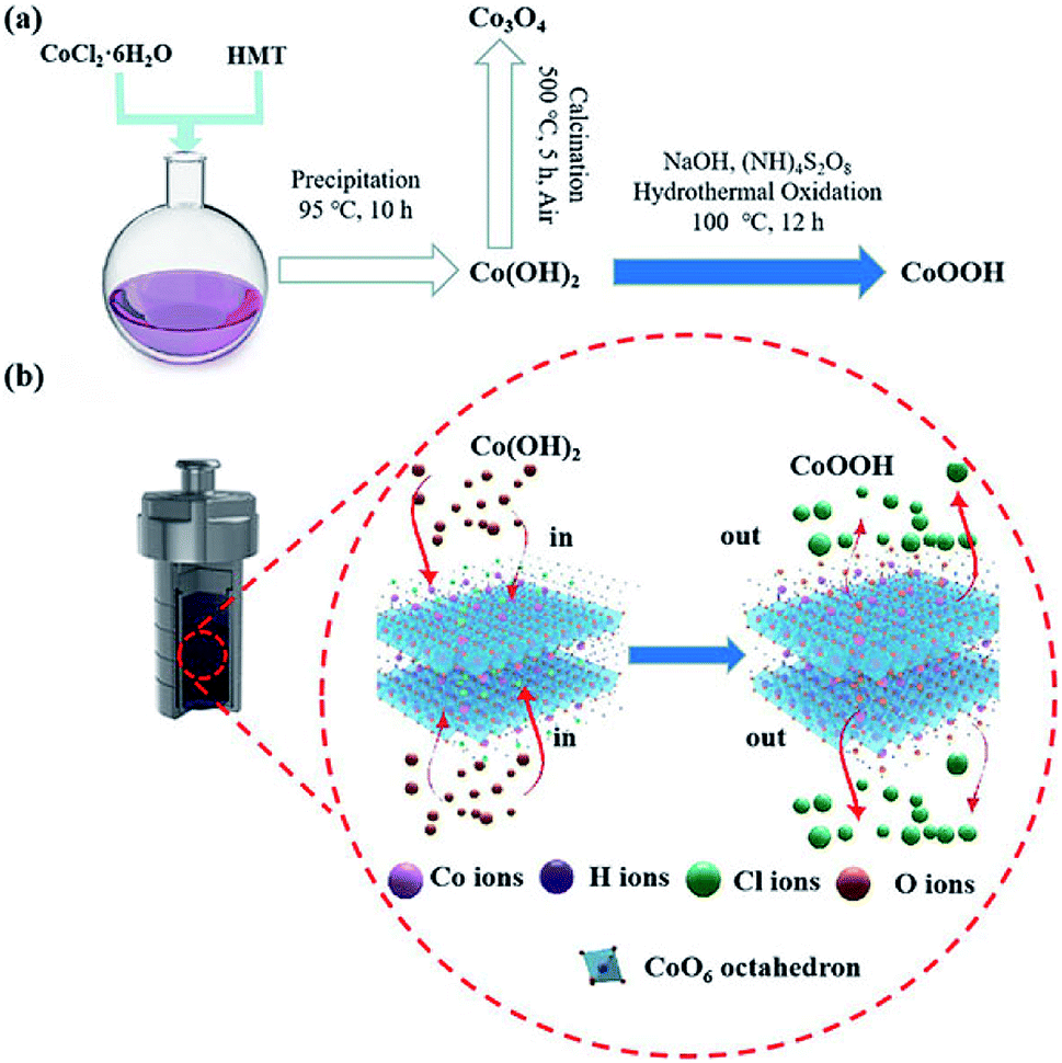
The synthesis procedure of the CoOOH nanosheets involves precipitation and oxidation, as illustrated in Fig. 1a. Initially, CoCl2·6H2O and HMT were dissolved in deionized water with stirring. Next, the solution was kept at 95 °C for 10 h, and a Co(OH)2 suspension was obtained. After oxidation, Co(OH)2 was transformed into CoOOH. The porous structure of the material was well formed by the release of methanol21 and NH3 gases during the precipitation and hydrothermal oxidation process.22 The synthetic mechanism of CoOOH nanosheets through the hydrothermal oxidation of Co(OH)2 nanosheets is shown in Fig. 1b. Co(OH)2 is obtained from the octahedral structure of Co2+, the apex of the octahedra is occupied by Cl−. After hydrothermal oxidation in the NaOH and (NH)4S2O8 solution, Cl− is substituted by oxygen in the CoO6 octahedra, and the Co(OH)2 nanosheets are converted into porous CoOOH nanosheets.23–25 Co3O4 nanosheets are obtained by thermal calcination of the Co(OH)2 nanosheets.
 |
| | Fig. 1 (a) Schematic of the synthesis routes of the Co(OH)2, CoOOH, and Co3O4 nanosheets; (b) synthesis mechanism of CoOOH nanosheets by the hydrothermal oxidation of Co(OH)2 nanosheets. | |
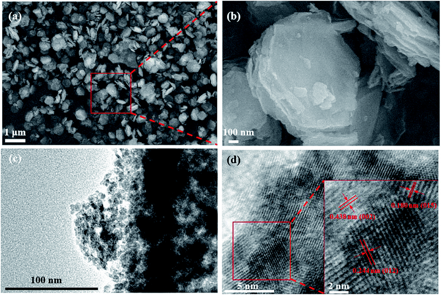
The SEM images of CoOOH are shown in Fig. 2a and b, and those of Co(OH)2 and Co3O4 are shown in Fig. S1a and b.† Co(OH)2 shows a nanosheet-like morphology, similar to the morphological features of CoOOH and Co3O4 samples. A layered structure is widely believed to increase the number of adsorbed charge species, which is beneficial for Li+ diffusion and reduction of the interfacial resistance. The TEM images of CoOOH are shown in Fig. 2c and d. Fig. 2c illustrates that the CoOOH nanosheets are composed of numerous small nanoparticles (∼10 nm).26 These nanoparticles provide a large surface area and abundant adsorption sites for Li+ storage. Void spaces in the CoOOH nanosheets can facilitate redox reactions by shortening the Li+ diffusion distance. Fig. 2d shows the high-resolution TEM image of CoOOH; a distinct lattice fringe with a spacing of 0.244 nm, which corresponds to the (012) plane, can be clearly observed in the inset in the figure. The TEM images of Co(OH)2 and Co3O4 are shown in Fig. S1c and d.†
 |
| | Fig. 2 (a) SEM image of the CoOOH nanosheets; (b) high-magnification image of (a); (c) TEM image of the CoOOH nanosheets; (d) high-resolution TEM image of (c). | |
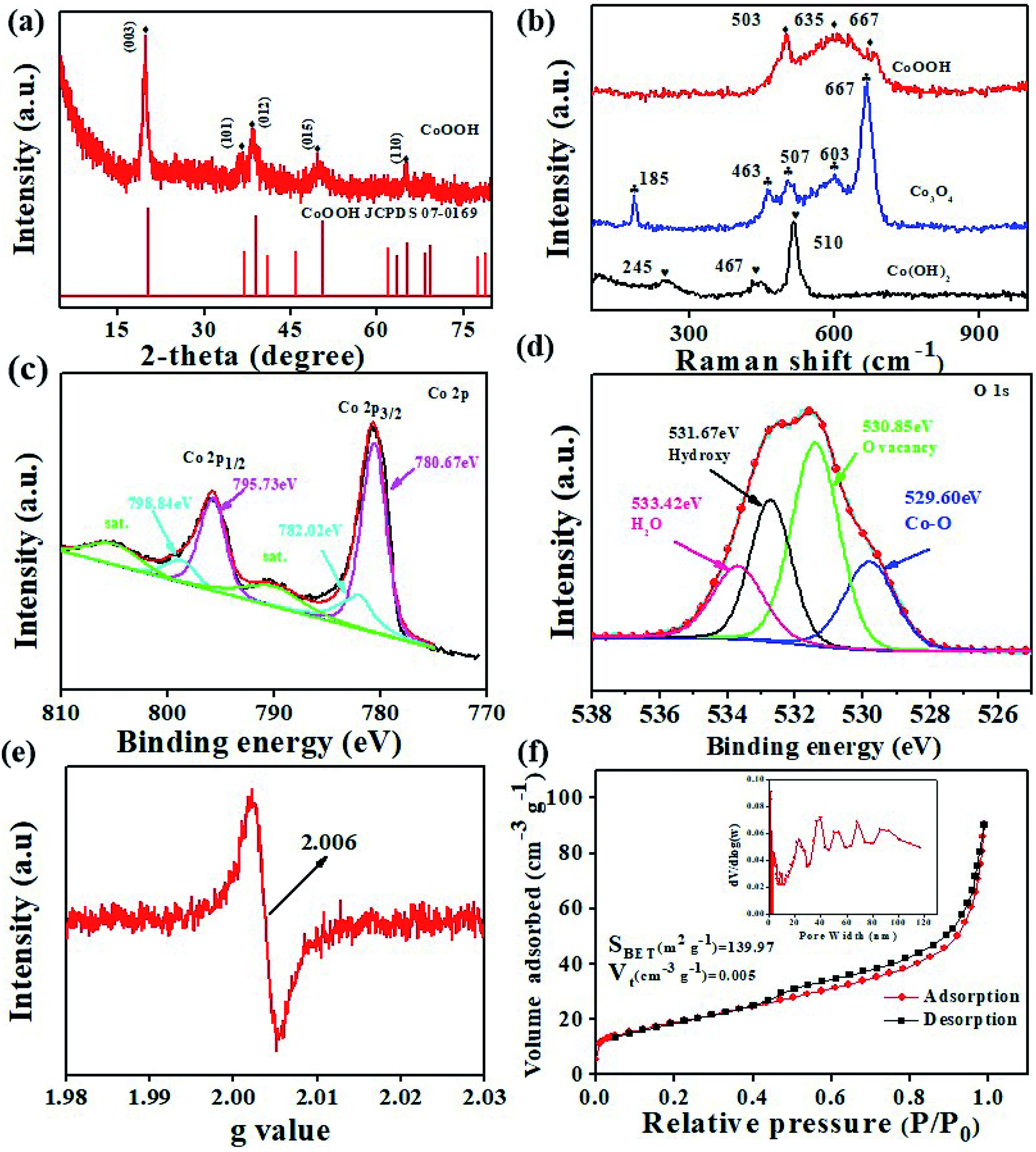
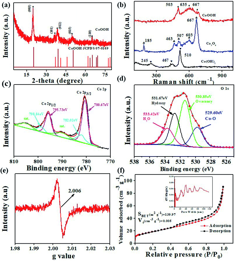
The XRD pattern shown in Fig. S2† confirms the presence of the Co(OH)2 phase.27 The XRD pattern shown in Fig. 3a matches the hexagonal layered structure of CoOOH (JCPDS card no. 07-0169) well. This finding indicates that Co(OH)2 could be successfully converted into CoOOH after oxidation. The red curve in Fig. S2† confirms the formation of Co3O4 (JCPDS card no. 42-1467) after Co(OH)2 is annealed. The crystallite size of the anode materials is calculated using the Debye–Scherrer formula (D = Kλ/βcosθ). The microcrystalline sizes of Co(OH)2, CoOOH, and Co3O4 are determined to be 16.05, 11.92, and 20.64 nm, respectively. Among the samples, CoOOH shows the smallest microcrystalline size. This feature reflects the ability of the material to form a large number of grain boundaries, which benefits the availability of diffusion channels for Li+.28
 |
| | Fig. 3 (a) XRD pattern of the CoOOH nanosheets; (b) Raman spectra of the CoOOH, Co(OH)2, and Co3O4 nanosheets; high-resolution XPS spectra of (c) Co 2p and (d) O 1s; (e) EPR spectrum of the CoOOH nanosheets; (f) nitrogen adsorption–desorption isotherm curves and the BJH pore diameter distribution (inset) of the CoOOH nanosheets. | |
Fig. 3b shows the typical Raman spectra of the CoOOH, Co(OH)2, and Co3O4 nanosheets. As highlighted previously, Co3+ (3d6) in CoOOH is located at octahedral sites.29 Raman “fingerprints” attributed to CoOOH, including peaks at 503 and 635 cm−1, could be observed.30 The peaks appearing at 185 (F2g), 463 (Eg), 507 (F2g), 603 (F2g), and 667 (A1g) cm−1 nearly completely match those of the pure Co3O4 spinel structure.15 The peaks appearing at 463 (Co3O4) and 467 cm−1 (Co(OH)2) correspond to O–Co–O bending vibrations.31–33 XPS characterization was applied to reveal the valence of cation and the existence of oxygen vacancies (VO) in CoOOH. Fig. S3† shows the full-survey XPS spectrum of CoOOH, and Fig. 3c and d show the high-resolution XPS spectra of Co 2p and O 1s, respectively. In the survey spectrum, the main peaks can be attributed to Co 2p, O 1s, and C 1s. The high-resolution XPS spectrum of Co 2p can be mainly split into four peaks. The distinct peaks at 795.73 and 780.67 eV are assigned to Co3+, and the distinct peaks at 798.84 and 782.02 eV are assigned to Co2+.14,34,35 The high-resolution XPS spectrum of O 1s also can be split into four peaks. The intense bands at 533.42, 531.67, 530.85, and 529.60 eV are attributed to the adsorption of water molecules on CoOOH, oxygen from OH groups,23 VO,36,37 and Co–O, respectively. The percent of the VO peak is calculated to be 47.33%, indicating the existence of rich VO in the structure. Furthermore, EPR was applied to confirm the presence of VO. The EPR results (Fig. 3e) demonstrate a relatively strong signal of CoOOH at g = 2.006, indicating the presence of VO in CoOOH, which agrees well with the XPS result.35,38 VO in CoOOH can promote Li+ diffusion, reduce the charge transfer resistance (Rct), and improve the capacity and rate performance of the CoOOH anode. N2 adsorption/desorption test results, which verify the hierarchical porous structure of the CoOOH nanosheets, are depicted in Fig. 3f. The surface area of the nanosheets is calculated to be 139.97 m2 g−1, the total pore volume is 0.005 cm3 g−1, and the pore size ranges from 2 to 120 nm. A highly exposed surface area is typically believed to increase the number of adsorbed charge species. Porous structures with different pore sizes offer sufficient voids to accelerate phase transition and restrain the crumbling and cracking of the electrode. The TG curve of the CoOOH sample in the temperature range of 25–600 °C is shown in Fig. S4.† From Fig. S4a† it can be seen that the CoOOH underwent a weight loss in three steps, which is indicated by the zones I, II, and III. The weight loss below 100 °C can be ascribed to the removal of the adsorbed water. The total weight loss of 10.95% between 100 and 200 °C can be ascribed to the evaporation of the intercalated water molecules. The domain III ranging from 200 to 300 °C is associated with the loss of water produced by the dehydroxylation of the hydroxide layers.39,40 The total weight loss (∼17.81%) is consistent with the expected value (19.3%) for the stoichiometric composition of CoOOH.14,30
Electrochemical performance
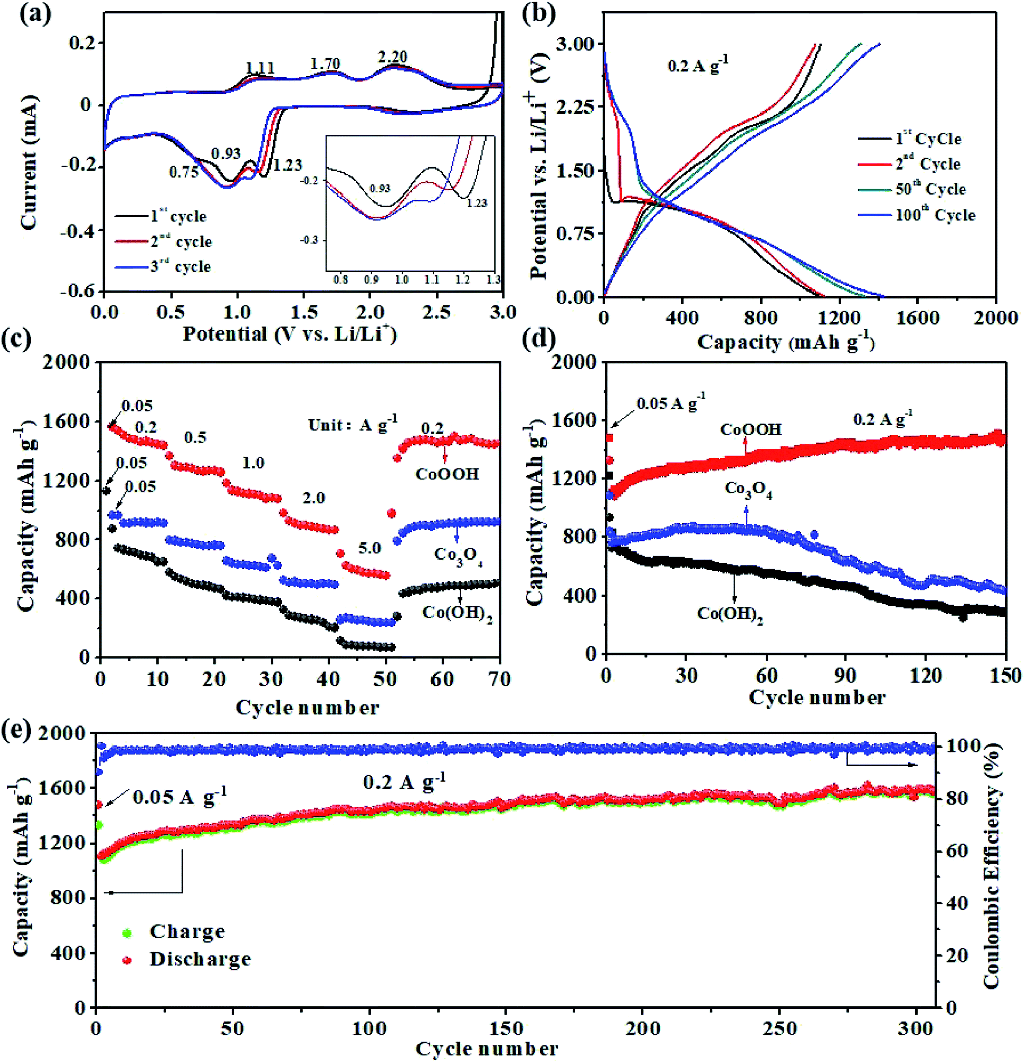
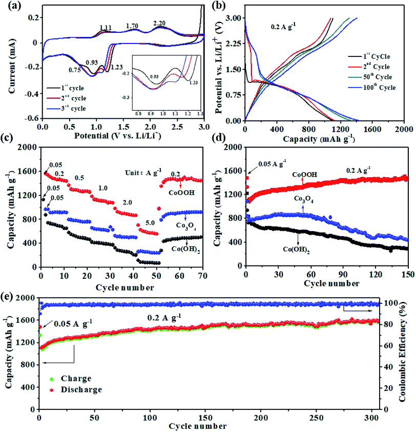
The electrochemical properties of the CoOOH, Co(OH)2, and Co3O4 nanosheets as anode materials for LIBs are evaluated. Fig. 4a illustrates the cyclic voltammetry (CV) curves of the CoOOH electrode for the first three cycles at a scan rate of 0.1 mV s−1. In the first cycle, the reduction peak at 1.23 V could be assigned to the transition of Co3+ to Co2+. The subsequent reduction peak at 0.93 V is characteristic of the reduction of Co2+ to Co, and the reduction peak at 0.75 V is due to the formation of a solid-electrolyte interface (SEI) film.41,42 The oxidation peak at 1.11 V reflects the reversible transition from Co to Co(II),26 and the oxidation peak at 1.70 V could be ascribed to the transition of Co2+ to Co3+. Another oxidation peak observed at 2.20 V corresponds to the formation of Co(III).43 However, because of the improvement in reaction kinetics of the system after the first lithiation, the reduction peak shifts toward a lower potential in the second and following cycles. This result indicates that reduction polarization maintains the cycling process of Co(III) to Co.26 The voltage profiles of the CoOOH electrode for the 1st, 2nd, 50th, and 100th cycles are presented in Fig. 4b. In the first cycle, discharge and charge capacities of 1478 and 1330 mA h g−1 could be obtained at 0.2 A g−1, respectively, which correspond to an ICE of approximately 90.0%. The following discharge profiles of the CoOOH electrode nearly overlap, thus suggesting the good stability and reversibility of the electrode. From the 2nd cycle to the 100th cycle, the charge profiles of the electrode reveal two stable plateaus at 1.7 and 2.2 V, which is consistent with the oxidation peaks in the CV curves. The discharge curve exhibits an obvious plateau at approximately 1.0 V, which is consistent with the reduction peak in the CV curves. The high ICE of the CoOOH electrode can be attributed to its rapid and complete conversion reaction upon lithiation/delithiation facilitated by hydroxyl groups and VO, which will be further discussed in the following DFT calculation results.
 |
| | Fig. 4 (a) CV curves of the CoOOH electrode at 0.1 mV s−1; (b) voltage profiles of the CoOOH electrode for the 1st, 2nd, 50th, and 100th cycles at 0.2 A g−1; (c) rate performance of the CoOOH, Co3O4, and Co(OH)2 electrodes from 0.2 A g−1 to 5 A g−1; (d) cycling performance of the CoOOH, Co3O4, and Co(OH)2 electrodes at 0.2 A g−1; (e) long-term cycling performance of the CoOOH electrode at 0.2 A g−1 and the corresponding coulombic efficiency. | |
The rate capability of the prepared electrodes is evaluated at various current densities (Fig. 4c). The anodic materials could be activated at 0.05 A g−1 for the first cycle. The rate performance of the CoOOH electrode is clearly higher than those of the Co3O4 and Co(OH)2 electrodes. The average reversible discharge capacities of the CoOOH electrode at current densities of 0.2, 0.5, 1, 2, and 5 A g−1 are 1472, 1261, 1092, 887, and 574 mA h g−1, respectively. When the current density is reduced from 5 A g−1 to 0.2 A g−1, a discharge capacity of 1461 mA h g−1 is still recovered, thus suggesting the excellent reversibility of the electrode for lithium storage. This excellent rate performance may be ascribed to the rapid conversion reaction of CoOOH upon lithiation/delithiation facilitated by its nanoporous structure and high electronic conductivity.
Electrochemical tests are carried out at a current density of 0.2 A g−1 to understand the stability of the prepared electrodes (Fig. 4d and e). The results show that the CoOOH electrode possesses a cycling stability superior to those of the Co3O4 and Co(OH)2 electrodes. The initial discharge capacity of the CoOOH electrode is 1478.2 mA h g−1. The electrode is then activated, and its discharge capacity increases to 1588.5 mA h g−1, which is higher than its theoretical specific capacity of 1457 mA h g−1, after 300 cycles. The consequent increase in capacity is commonly observed in cobalt oxide-based anodes,28 because the extraction of Li+ leaves a hierarchical pore structure in the CoOOH matrix, generating the additional active sites for further interfacial Li storage.44 The coulombic efficiency of the CoOOH electrode exceeds 98.5% (0.2 A g−1) at the fifth charge/discharge cycle (Fig. 4e), thus reflecting the excellent stability of the SEI film. To the best of our knowledge, the prepared CoOOH electrode shows the highest ICE and the best cycling stability compared to previously reported metal oxide anodes for LIBs. A comparison of the cycling stability and ICE of the CoOOH anode with previously reported cobalt oxide anodes for LIBs is given in Table S1,† and the cycling performance of the prepared electrodes at 3 A g−1 is shown in Fig. S5.† The results confirm that the CoOOH electrode displays better long-term cycling performance than the Co3O4 and Co(OH)2 electrodes at a higher current density.
An electrical impedance spectroscopy (EIS) study was further carried out and the Nyquist plots of CoOOH, Co3O4, and Co(OH)2 electrodes are shown in Fig. S6.† In Fig. S6a,† the semicircle observed at high to medium frequencies is associated with the Rct,9,45,46 and the Rct (173 Ω) of the CoOOH electrode is much lower than that of Co3O4 (225 Ω) and Co(OH)2 (187 Ω) electrodes. This result reflects the enhanced electronic conductivity of the CoOOH electrode.43 The derived Li+ diffusion coefficients (DLi+) (5.07 × 10⁻¹⁷ cm2 s−1) of the CoOOH electrode are approximately four to five orders of magnitude higher than that of the Co(OH)2 electrode (2.87 × 10⁻²¹ cm2 s−1) and Co3O4 electrode (5.91 × 10⁻²² cm2 s−1) (Fig. S6b–d†). The efficient ion transport and reduced overall impedance of the CoOOH electrode may improve the rate capability and help minimize heat generation which is beneficial to cycling stability and battery safety during high-rate operation. The SEM image shown in Fig. S7† clearly reveals that the CoOOH electrode (Fig. S7a†) essentially retains its sheet-like structure even after 300 cycles. The high-resolution TEM micrograph provided further illustrates the microstructure of the CoOOH electrode. Specifically, small particles are detected after 300 cycles. The high-resolution TEM image provided in Fig. S7d† clearly exhibits interplanar spacings of 0.243 and 0.204 nm, which respectively correspond to the (012) and (015) lattice planes of CoOOH. These results confirm the structural stability of the CoOOH electrode. The SEM and high-resolution TEM images of the Co(OH)2 and Co3O4 electrodes are also shown in Fig. S7b, c, e, and f.†
The electrochemical kinetics of the electrodes are investigated by CV measurements at various scan rates to disclose the origin of the excellent rate capability and cycling stability of the CoOOH electrode (Fig. 5a).47,48 The relationship between peak current (i) and sweep rate (v) can be described using eqn (1) and (2).
| | | log(i) = blog(v) + log(a) | (2) |
where
a and
b are adjustable constants. In general, values of
b close to 0.5 indicate a diffusion-controlled process, whereas values of
b approaching 1.0 represent a capacitive process.
49 Plotting log(
i)
versus log(
v) yields
b values of 0.8363, 0.5161, 0.4823, 0.4361, and 0.6197 for the anodic and cathodic peaks (
Fig. 5b), and these values indicate that the majority of the current at the peak potential is controlled by a diffusion process.
25 These results demonstrate that diffusion dominates the reaction of the as-prepared CoOOH electrode with relatively fast kinetics.
34 However, the Co
3O
4 and Co(OH)
2 electrodes exhibit a capacitance-controlled behavior (Fig. S8 and S9
†).
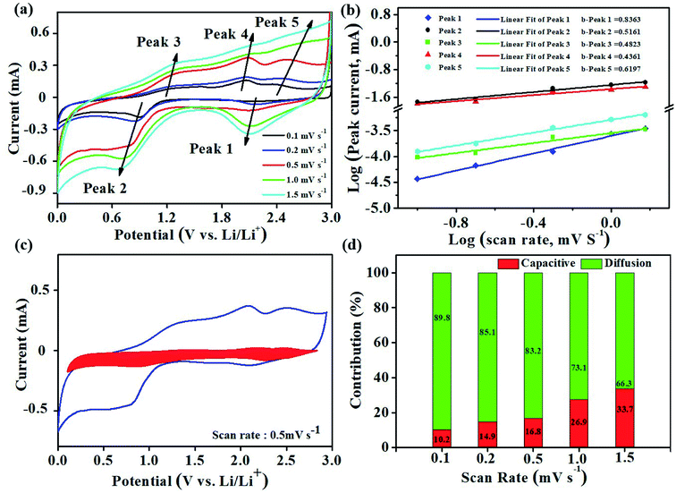 |
| | Fig. 5 Kinetic analysis of the electrochemical behavior of the CoOOH electrode versus Li+/Li. (a) CV curves at various scan rates ranging from 0.1 to 1.5 mV s−1; (b) determination of b values using the relationship between the peak current and scan rate according to the voltammograms in (a); (c) separation of the capacitive and diffusion currents at a scan rate of 0.5 mV s−1; (d) contribution ratios of the capacitive and diffusion-controlled effects at various scan rates. | |
The relationship in eqn (1) can be divided into two parts corresponding to capacitive (k1ν) and diffusion-limited effects (k2ν1/2) as follows:
where
k1 and
k2 are constants and can be fitted from the plot of
i/
ν1/2versus v1/2. At a scan rate of 0.5 mV s
−1 (
Fig. 5c), the capacitance contributes ∼16.8% of the total current.
Fig. 5d shows that the CoOOH electrode contributes 10.2% of the pseudo capacitance at a scan rate of 0.1 mV s
−1, this contribution gradually improves to 33.7% at 1.5 mV s
−1. The high diffusion contribution is mainly attributed to the hierarchical nanoporous structure and high electronic conductivity of CoOOH.
The kinetics of Li+ diffusion coefficient (DLi+) of the CoOOH electrode is also investigated by CV at various scan rates (Fig. 5a) and calculated using the Randles–Sevcik equation (Ip = (2.69 × 10⁵)n3/2SD1/2C0v1/2).50 According to the linear fitting results of Ip and v1/2 (Fig. S8d, S9d, and S10†), the DLi+ of the CoOOH electrode is estimated to be 5.13 × 10⁻¹⁴ cm2 s−1, which is three orders of magnitude greater than that of Co(OH)2 (1.5 × 10⁻¹⁷ cm2 s−1) and Co3O4 (8.42 × 10⁻¹⁷ cm2 s−1) electrodes.
DFT calculation results
The detailed conversion reaction process between Li+ and CoOOH is investigated using DFT calculations based on the (001) facet of CoOOH (a 3 × 3 supercell model is shown in Fig. S11†) to characterize the enhanced lithium storage performance of the CoOOH electrode. The reaction of CoOOH with Li+ involves the following steps:
Step 1: adsorption of Li+ in O active sites and formation of Li2O; desorption of Li2O and formation of CoOOH–VO (the model of the process is shown in Fig. S12†).
| | | CoOOH + Li+ + e− → CoOOH–Li ΔG1 (−3.34 eV) | (4) |
| | | CoOOH–Li + Li+ + e− → CoOOH–2Li ΔG2 (−4.60 eV) | (5) |
| | | CoOOH–2Li → CoOOH–VO + Li2O ΔG3 (14.16 eV) | (6) |
Step 2: adsorption of Li+ in a OH active site of CoOOH–VO and formation of LiH or LiOH; desorption of LiH and formation of H vacancies (VH) (the model of the process is shown in Fig. S13†); or desorption of LiOH and formation of OH vacancies (VOH).
| | | CoOOH–VO + Li+ + e− → CoOOH–VO–Li ΔG4 (0.52 eV) | (7) |
| | | CoOOH–VO–Li → CoOOH–VO–VH ΔG5 (−3.74 eV) | (8) |
| | | CoOOH–VO–Li → CoOOH–VO–VOH + Li2O ΔG6 (−11.76 eV) | (9) |
Step 3: adsorption of Li+ in the O active site of the VH and formation of Li2O; desorption of Li2O and formation of CoOOH–VO–VH–VO (the model of the process is shown in Fig. S14†).
| | | CoOOH–VO–VH + Li+ + e− → CoOOH–VO–VH–Li ΔG7 (−4.56 eV) | (10) |
| | | CoOOH–VO–VH–Li + Li+ + e− → CoOOH–VO–VH–2Li ΔG8 (−2.68 eV) | (11) |
| | | CoOOH–VO–VH–2Li → CoOOH–VO–VH–VO + Li2O ΔG9 (0.81 eV) | (12) |
The calculation results show that the conversion reaction products contain LiH, LiOH, and Li2O. Thus, the decomposition reactions of LiH, LiOH, and Li2O are further investigated using DFT calculations, and the following results are obtained:
| | | LiH → Li+ + H− ΔG10 (0.51 eV) | (13) |
| | | LiOH → Li+ + OH− ΔG11 (0.95 eV) | (14) |
| | | Li2O → 2Li+ + O2− ΔG12 (1.28 eV) | (15) |
The Gibbs free energies of the decomposition reactions of LiH, LiOH, and Li2O are calculated to be 0.51, 0.95, and 1.28 eV, respectively. The results indicate that the reversibilities of the formed LiH and LiOH are superior to that of Li2O. The ICE of the CoOOH electrode (90.0%) is much higher than that of the Co3O4 (72.6%) and Co(OH)2 (76.3%) electrodes. Moreover, the rate performance of the CoOOH electrode is clearly superior to that of the Co3O4 and Co(OH)2 electrodes. These DFT calculation and experiment results further confirm that hydroxyl groups facilitate the rapid and complete conversion reaction of CoOOH upon lithiation/delithiation.
Conclusions
In summary, CoOOH nanosheets were successfully prepared using a facile one-pot method. The CoOOH anode showed higher capacity, cycling stability, and rate capability compared to Co(OH)2 and Co3O4 electrodes when applied to LIBs. The stable porous nanosheet structure, high Li+ diffusion coefficient, and excellent conductivity of the CoOOH nanosheets contributed to the CoOOH anode's outstanding initial discharge capacity of 1478 mA h g−1 at 0.2 A g−1, prominent rate capability (574 mA h g−1 at 5 A g−1), and excellent cyclability (1588 mA h g−1 after 300 cycles). Thus, the prepared material demonstrates potential application as a promising LIB anode material. Experiments and DFT calculations confirmed that the CoOOH anode has a high ICE (90%) due to its numerous hydroxyl groups and VO. This study provides a new design concept for transition-metal oxyhydroxide anode materials for LIBs.
Conflicts of interest
The authors have no conflicts to declare.
Acknowledgements
We thank the Shenzhen Basic Research Project (No. JCYJ20170818092720054, JCYJ20190808145203535, and JCYJ20190808144413257), the National Natural Science Foundation of China (No. 21671136), the Project of Natural Science Foundation of Guangdong Province (No. 2020A1515010379 and 2014A030311028), the Major Programs for Science and Technology Development of Shenzhen (No. XCL201110060), and the Major Industrial Projects of Shenzhen (No. s2017001850011) for providing financial support for this work. We are grateful to the Instrumental Analysis Center of Shenzhen University (Xili Campus) for providing the facilities for our material analyzes.
References
- H. Liu, Z. Zhu, Q. Yan, S. Yu, X. He, Y. Chen, R. Zhang, L. Ma, T. Liu, M. Li, R. Lin, Y. Chen, Y. Li, X. Xing, Y. Choi, L. Gao, H. S. Cho, K. An, J. Feng, R. Kostecki, K. Amine, T. Wu, J. Lu, H. L. Xin, S. P. Ong and P. Liu, Nature, 2020, 585, 63–67 CrossRef CAS PubMed.
- J. Chen, X. Fan, Q. Li, H. Yang, M. R. Khoshi, Y. Xu, S. Hwang, L. Chen, X. Ji, C. Yang, H. He, C. Wang, E. Garfunkel, D. Su, O. Borodin and C. Wang, Nat. Energy, 2020, 5, 386–397 CrossRef CAS.
- C. Xu, K. Marker, J. Lee, A. Mahadevegowda, P. J. Reeves, S. J. Day, M. F. Groh, S. P. Emge, C. Ducati, B. Layla Mehdi, C. C. Tang and C. P. Grey, Nat. Mater., 2020 DOI:10.1038/s41563-020-0767-8.
- X. Wang, G. Pawar, Y. Li, X. Ren, M. Zhang, B. Lu, A. Banerjee, P. Liu, E. J. Dufek, J. G. Zhang, J. Xiao, J. Liu, Y. S. Meng and B. Liaw, Nat. Mater., 2020, 19, 1339–1345 CrossRef CAS PubMed.
- U. Pal, F. Chen, D. Gyabang, T. Pathirana, B. Roy, R. Kerr, D. R. MacFarlane, M. Armand, P. C. Howlett and M. Forsyth, J. Mater. Chem. A, 2020, 8, 18826–18839 RSC.
- S. Liu, Q. Zhao, X. Zhang, J. Liu, L. Dai, L. Wang and J. Luo, J. Mater. Chem. A, 2020, 8, 17415–17419 RSC.
- L. Li, Z. Xie, G. Jiang, Y. Wang, B. Cao and C. Yuan, Small, 2020, 16, 2001526 CrossRef CAS PubMed.
- N. Mahmood, T. Tang and Y. Hou, Adv. Energy Mater., 2016, 6, 1600374 CrossRef.
- Q. Qu, T. Gao, H. Zheng, X. Li, H. Liu, M. Shen, J. Shao and H. Zheng, Carbon, 2015, 92, 119–125 CrossRef CAS.
- Y. Huang, Y. Fang, X. Lu, D. Luan and X. Lou, Angew. Chem., Int. Ed., 2020, 59, 19914–19918 CrossRef CAS PubMed.
- J. Li, F. Li, J. Liao, H. Li, D. Dang, Q. Liu and H. Peng, Adv. Mater. Interfaces, 2020, 7, 2000667 CrossRef CAS.
- Z. Chang, H. Li, H. Tang, X. Z. Yuan and H. Wang, Int. J. Hydrogen Energy, 2009, 34, 2435–2439 CrossRef CAS.
- S. H. Ye, Z. X. Shi, J. X. Feng, Y. X. Tong and G. R. Li, Angew. Chem., Int. Ed., 2018, 57, 2672–2676 CrossRef CAS PubMed.
- Z. Wang, L. Wang, S. Liu, G. Li and X. Gao, Adv. Funct. Mater., 2019, 29, 1901051 CrossRef.
- D. Chernysheva, C. Vlaic, I. Leontyev, L. Pudova, S. Ivanov, M. Avramenko, M. Allix, A. Rakhmatullin, O. Maslova, A. Bund and N. Smirnova, Solid State Sci., 2018, 86, 53–59 CrossRef CAS.
- H. J. Monkhorst and J. Pack, Phys. Rev. B: Solid State, 1976, 13, 5188–5192 CrossRef.
- P. E. Blöchl, Phys. Rev. B: Condens. Matter Mater. Phys., 1994, 50, 17953–17979 CrossRef PubMed.
- G. Kresse and D. Joubert, Phys. Rev. B: Condens. Matter Mater. Phys., 1999, 59, 1758–1775 CrossRef CAS.
- J. P. Perdew, K. Burke and M. Ernzerhof, Phys. Rev. Lett., 1996, 77, 3865–3868 CrossRef CAS PubMed.
- B. Hammer, L. B. Hansen and J. K. Nørskov, Phys. Rev. B: Condens. Matter Mater. Phys., 1999, 59, 7413–7421 CrossRef.
- C. Li, X. Yin, Q. Li, L. Chen and T. Wang, Chem.–Eur. J., 2011, 17, 1596–1604 CrossRef CAS PubMed.
- X. Liu, R. Ma, Y. Bando and T. Sasaki, Angew. Chem., Int. Ed., 2010, 49, 8253–8256 CrossRef CAS PubMed.
- Q. Wu, X. Gao, G. Li, G. Pan, T. Yan and H. Zhu, J. Phys. Chem. C, 2007, 111, 17082–17087 CrossRef CAS.
- H. Wu, W. Sun, J. Shen, D. W. Rooney, Z. Wang and K. Sun, Nanoscale, 2018, 10, 10221–10231 RSC.
- M. Figlarz, J. Guenot and F. Fievet-vincent, J. Mater. Sci., 1976, 11, 2267–2270 CrossRef CAS.
- V. Pralong, A. Delahaye-Vidal, B. Beaudoin, B. Gerand and J. Tarascon, J. Mater. Chem., 1999, 9, 955–960 RSC.
- R. Ma, Z. Liu, K. Takada, K. Fukuda, Y. Ebina, Y. Bando and T. Sasaki, Inorg. Chem., 2006, 45, 3964–3969 CrossRef CAS PubMed.
- Z. Chen, Y. Gao, X. Chen, B. Xing, C. Zhang, S. Wang, T. Liu, Y. Liu and Z. Zhang, Ionics, 2019, 25, 5779–5786 CrossRef CAS.
- Q. Wu, X. Gao, G. Li, G. Pan, T. Yan and H. Zhu, J. Phys. Chem. C, 2007, 111, 17082–17087 CrossRef CAS.
- J. Yang, H. Liu, W. N. Martens and R. L. Frost, J. Phys. Chem. C, 2010, 114, 111–119 CrossRef CAS.
- Y. Liu, N. Fu, G. Zhang, M. Xu, W. Lu, L. Zhou and H. Huang, Adv. Funct. Mater., 2017, 27, 1605307 CrossRef.
- S. M. Youssry, I. El-Hallag, R. Kumar, G. Kawamura, A. Matsuda and M. El-Nahass, J. Electroanal. Chem., 2020, 857, 113728 CrossRef CAS.
- C. Lai, J. Alloys Compd., 2019, 777, 492–498 CrossRef CAS.
- Y. Wu, J. Meng, Q. Li, C. Niu, X. Wang, W. Yang, W. Li and L. Mai, Nano Res., 2017, 10, 2364–2376 CrossRef CAS.
- S. Ye, Y. Zhang, W. Xiong, T. Xu, P. Liao, P. Zhang, X. Ren, C. He, L. Zheng, X. Ouyang, Q. Zhang and J. Liu, Nanoscale, 2020, 12, 11079–11087 RSC.
- Q. Gan, H. He, K. Zhao, Z. He, S. Liu and S. Yang, ACS Appl. Mater. Interfaces, 2018, 10, 7031–7042 CrossRef CAS PubMed.
- J. Hao, S. Peng, H. Li, S. Dang, T. Qin, Y. Wen, J. Huang, F. Ma, D. Gao, F. Li and G. Cao, J. Mater. Chem. A, 2018, 6, 16094–16100 RSC.
- J. Wang, L. Li, H. Tian, Y. Zhang, X. Che and G. Li, ACS Appl. Mater. Interfaces, 2017, 9, 7100–7107 CrossRef CAS PubMed.
- Z. Liu, R. Ma, M. Osada, K. Takada and T. Sasaki, J. Am. Chem. Soc., 2005, 127, 13869–13874 CrossRef CAS PubMed.
- Q. Zhang, J. Wang, J. Dong, F. Ding, X. Li, B. Zhang, S. Yang and K. Zhang, Nano Energy, 2015, 13, 77–91 CrossRef CAS.
- S. Abouali, M. Garakani, B. Zhang, H. Luo, Z. Xu, J. Huang, J. Huang and J. Kim, J. Mater. Chem. A, 2014, 2, 16939–16944 RSC.
- J. S. Yeoh, C. F. Armer and A. Lowe, Mater. Today Energy, 2018, 9, 198–222 CrossRef.
- Z. Chen, C. X. Kronawitter, Y. Yeh, X. Yang, P. Zhao, N. Yao and B. Koel, J. Mater. Chem. A, 2017, 5, 842–850 RSC.
- H. Sun, G. Xin, T. Hu, M. Yu, D. Shao, X. Sun and J. Lian, Nat. Commun., 2014, 5, 4526 CrossRef CAS PubMed.
- K. Zhao, F. Liu, C. Niu, W. Xu, Y. Dong, L. Zhang, S. Xie, M. Yan, Q. Wei, D. Zhao and L. Mai, Adv. Sci., 2015, 2, 1500154 CrossRef PubMed.
- Y. Dong, Y. Ma, Y. Li, M. Niu, J. Yang, X. Song, D. Li, Y. Liu and J. Zhang, Nanoscale, 2019, 11, 21180–21187 RSC.
- G. Huang, F. Zhang, X. Du, J. Wang, D. Yin and L. Wang, Chem.–Eur. J., 2014, 20, 11214–11219 CrossRef CAS PubMed.
- F. G. da Silva, J. Depeyrot, A. F. C. Campos, R. Aquino, D. Fiorani and D. Peddis, J. Nanosci. Nanotechnol., 2019, 19, 4888–4902 CrossRef CAS PubMed.
- H. Kim, J. Cook, S. Tolbert and B. Dunn, J. Electrochem. Soc., 2015, 162, A5083–A5090 CrossRef CAS.
- B. Lu, J. Liu, R. Hu, H. Wang, J. Liu and M. Zhu, J. Mater. Chem. A, 2017, 5, 8555–8565 RSC.
Footnotes |
| † Electronic supplementary information (ESI) available. See DOI: 10.1039/d0ta10389f |
| ‡ Yonghuan Fu and Liewu Li contributed equally to this work. |
|
| This journal is © The Royal Society of Chemistry 2021 |
Click here to see how this site uses Cookies. View our privacy policy here. 
 ab,
Shenghua
Ye
a,
Penggang
Yang
a,
Peng
Liao
d,
Xiangzhong
Ren
ab,
Shenghua
Ye
a,
Penggang
Yang
a,
Peng
Liao
d,
Xiangzhong
Ren