
A coupled conductor of ionic liquid with Ti3C2 MXene to improve electrochemical properties†
Fangfang
Yan‡
ab,
Chuan
Zhang‡
c,
Haiyan
Wang
a,
Xiaguang
Zhang
a,
Hucheng
Zhang
 *a,
Huanli
Jia
ab,
Yang
Zhao
a and
Jianji
Wang
*a
*a,
Huanli
Jia
ab,
Yang
Zhao
a and
Jianji
Wang
*a
aCollaborative Innovation Centre of Henan Province for Green Manufacturing of Fine Chemicals, Key Laboratory of Green Chemical Media and Reactions, Ministry of Education, School of Chemistry and Chemical Engineering, Henan Normal University, Xinxiang, Henan 453007, China. E-mail: hzhang@htu.edu.cn; jwang@htu.edu.cn
bSchool of 3D Printing, Xinxiang University, Xinxiang, Henan 453003, P. R. China
cDepartment of Biomedical Engineering, University of Houston, Houston, TX 77204, USA
First published on 8th December 2020
Abstract
Ti3C2Tx MXene is regarded as a promising material in energy-related applications; however, the overscreening charge effect of the electric double layer on electrified interfaces, along with “inert” F terminations, limits the electrochemical operation efficiencies. Here, we developed a protocol to harvest a coupled conductor through confining in situ 1-ethyl-3-methylimidazolium ([Emim]+) ions into Ti3C2Tx interlayers. The ionic–electronic coupling does not require any external counterions, but activates terminal F and even sub-surface Ti, and endows the conductor with metal-like and ionophilic characteristics. Different from physically preintercalated or adsorbed ions, the resulting chemically confined [Emim]+ ions offer more accessible electroactive sites, faster electron transport in surface redox, and more efficient channels for ion transfer. Hence, the Ti3C2Tx electrodes present high gravimetric capacitance, rate performance and cycling stability. This work highlights the important roles of the coupling in the design and research of mixed ionic–electronic conductors with high electrochemical activity.
1. Introduction
MXenes are a new family of materials with a two-dimensional (2D) structure, and were firstly reported by Gogotsi's group in 2011.1 Their chemical formula can be expressed as Mn+1XnTx, where M is an early transition metal, X is carbon and/or nitrogen, and T represents surface terminations (![[double bond, length as m-dash]](https://www.rsc.org/images/entities/char_e001.gif) O, –OH, –F, and –Cl).2–4 So far, dozens of different MXenes have been successfully synthesized, and show many profound applications in supercapacitors,5–7 water purification,8 electrocatalysts,9,10 biosensors,11 batteries,12,13etc. Among them, Ti3C2Tx is identified as one of the most promising electrode materials in energy storage and electrocatalysis owing to their unique hydrophilic surfaces,14,15 high metallic conductivities,16,17 fast charge–discharge rates and theoretical capacity (615 C g−1), which are superior to those of carbon materials18 and comparable to those of typical pseudocapacitive oxide RuO2.19 Therefore, intensive efforts have been devoted to the Ti3C2Tx electrochemical performances.
O, –OH, –F, and –Cl).2–4 So far, dozens of different MXenes have been successfully synthesized, and show many profound applications in supercapacitors,5–7 water purification,8 electrocatalysts,9,10 biosensors,11 batteries,12,13etc. Among them, Ti3C2Tx is identified as one of the most promising electrode materials in energy storage and electrocatalysis owing to their unique hydrophilic surfaces,14,15 high metallic conductivities,16,17 fast charge–discharge rates and theoretical capacity (615 C g−1), which are superior to those of carbon materials18 and comparable to those of typical pseudocapacitive oxide RuO2.19 Therefore, intensive efforts have been devoted to the Ti3C2Tx electrochemical performances.
MXenes are generally produced by chemical extraction of A element layers from MAX phases in layered ternary metal carbides and/or nitrides,20–23 where mostly A represents group 13 and 14 elements in the periodic table, and the resultant termination species are heavily dependent on the etchant. At the beginning, HF aqueous solution is employed as the etchant, but the violent reaction of Ti3AlC2 with HF and tedious post-processing easily result in damage to Ti3C2Tx flakes and poor capacitance performances.24 Consequently, the milder LiF–HCl treatment becomes popular to harvest larger and intact flakes with low resistivity.25,26 However, these HF-based etchants inevitably introduce F terminal groups on MXenes. The mechanism investigations reveal that the O terminal groups are the electrochemically active sites for energy storage in acid electrolyte, while the F terminations block ion transport on the nanoflakes and limit the efficiencies in electrochemical energy storage.27
To bypass these dilemmas, recently, F-free Ti3C2Tx was successfully prepared via alkali-etching in 27.5 M NaOH at 543 K.28 The resulting Ti3C2Tx film electrode possessed more exposed electrochemically active sites, and exhibited a specific capacitance of 314 F g−1 in 1 M H2SO4. Although the capacitance performance can be significantly improved using F-free etchants, these approaches usually require harsh experimental conditions. In comparison, HF-based etching is commonly recognized as a facile and efficient route to obtain MXenes,29 but further improvements of electrochemical performances depend mainly on the full utilization of F terminal groups on F-rich MXenes. Currently, no reports are available in the literature for making use of the “inert” terminal F to improve the MXene electrochemical properties. Clearly, the surface chemistry is closely related to in situ chemical etching procedures, and the targeted-etching solutions will endow MXenes with enhanced performances in energy storage and catalysis.
Imidazolium-based salts are a popular class of room-temperature ionic liquids (ILs), and potential ideal electrolytes in emerging electrochemical technologies due to their high ionic conductivity, wide operation voltage window, excellent thermal stability, and strong hydrophilicity and hydrogen bonding. Recently, it has been demonstrated that IL–electrode interfaces represent unique heterogeneous structures rather than traditional electric double-layer features, and have been recognized as a crucial actor in governing all electrochemical reactions.30,31 Different from IL bulk, the interfacial effect drives cations and anions to orient alternately along electrified surfaces with a multilayered structure on the ionic scale.32,33 If ILs are confined in nanoscale spaces, they could appear as a solid-like phase or a so-called superionic state.34–36 These efforts defined well the IL structures at electrified interfaces, and confirmed that the counterions would exert an overscreening charge effect to limit the mass and electron transfer in electrochemical devices. The undesired overscreening can be significantly weakened by separating the interfacial positive and negative charges at much higher levels, or be greatly dispelled by implanting single cation or anion species into nanoconfined spaces. Clearly, the device without the overscreening effect should operate more efficiently in electrochemical energy storage and catalysis, but technologically has faced great challenges up to now.
Here, we developed a new targeted-etching strategy to chemically confine single ionic species into Ti3C2Tx flakes, and the ionic–electronic coupling was revealed from a combination of experimental measurements and density functional theory (DFT) calculations. Using 1-ethyl-3-methylimidazolium hexafluorophosphate ([Emim]PF6) and HCl (IL–HCl) as the etching agent, both [Emim]+ intercalation and Ti3C2Tx delamination can be completed in one step under mild operation conditions. This situation leads to coupling of cations ([Emim]+) with electronic 2D flakes (Ti3C2Tx) through F terminations instead of physical adsorption, namely the ionic–electronic coupling. The resultant coupled conductor with ionophilic interlayers exhibits high electrochemical activity. Besides protecting Ti3C2Tx against oxidation, the chemically confined [Emim]+ ions play vital roles in catalyzing the redox reaction on the MXene surfaces. The promoting mechanisms are unveiled by analyzing the unique electronic and structural characteristics of the coupled conductor. Conceptually, the studies on the ionic–electronic interactions open a new route to dispel the overscreening effect from the electrified interfaces and enhance the electrochemical performances through the coupling of single ion species with 2D nanosheets.
2. Experimental
2.1 Preparation of Ti3AlC2 powder
Ti3AlC2 powder was synthesized by a hot pressing sintering method. Typically, Ti powder (99.99 wt%, 300 mesh), Al powder (99.9 wt%, 200–400 mesh) and graphite powder (99.95 wt%, ≥325 mesh) were mixed according to the molar ratio 3![[thin space (1/6-em)]](https://www.rsc.org/images/entities/char_2009.gif) :1.2:2 in an agate jar, and ground for 24 h in the presence of absolute alcohol and agate balls. After drying in a vacuum oven for 12 h at 333 K, the powder mixture was carefully poured into a graphite die (30 mm diameter and 100 mm height). Then, the die was put in a hot pressing sintering furnace, heated to 1773 K with a ramp rate of 10 K min−1 and held for 1 h in an argon atmosphere with a pressure of 7 MPa. After cooling to room temperature, the resulting Ti3AlC2 block was mechanically crushed and ground using a mortar and pestle, and passed through a 400 mesh sieve to get the Ti3AlC2 powder.
:1.2:2 in an agate jar, and ground for 24 h in the presence of absolute alcohol and agate balls. After drying in a vacuum oven for 12 h at 333 K, the powder mixture was carefully poured into a graphite die (30 mm diameter and 100 mm height). Then, the die was put in a hot pressing sintering furnace, heated to 1773 K with a ramp rate of 10 K min−1 and held for 1 h in an argon atmosphere with a pressure of 7 MPa. After cooling to room temperature, the resulting Ti3AlC2 block was mechanically crushed and ground using a mortar and pestle, and passed through a 400 mesh sieve to get the Ti3AlC2 powder.
2.2 Preparation of IL-Ti3C2Tx flakes
IL-Ti3C2Tx flakes were prepared using [Emim]PF6–HCl aqueous solution as an etchant. In a given process, 1.314 g [Emim]PF6 and 20 mL 9 M HCl solution were mixed in a 50 mL centrifuge tube with magnetic stirring for 10 min. After adding 1 g Ti3AlC2 powder, the centrifuge tube was sealed and immersed in a water bath at 328 K with stirring for 24 h. Subsequently, 30 mL deionized (DI) water was added into the resulting suspension and centrifuged at 3000 rpm. The purification process was repeatedly carried out until the supernatant reached a pH of 6. [Emim]–Ti3C2Tx bulk was collected from the sediment transferred to a flask containing 200 mL DI water, and delaminated by ultrasonic treatment for 1 h in a flowing N2 atmosphere. Finally, the dark green supernatant was obtained by centrifugation at 3000 rpm for 30 min, and used as [Emim]–Ti3C2Tx flakes for electrochemical testing.2.3 Preparation of HF-Ti3C2Tx flakes
The preparation of HF-Ti3C2Tx flakes was similar to that of [Emim]–Ti3C2Tx flakes. In brief, 1 g Ti3AlC2 powder was slowly added into 20 mL HF aqueous solution (40%) at 313 K, and stirred for 38 h. The resulting suspension was repeatedly purified by centrifugation until the supernatant became neutral to obtain the HF-Ti3C2Tx bulk. Then, 15 mL dimethyl sulfoxide was added to intercalate HF-Ti3C2Tx bulk, and removed by centrifugation after stirring for 12 h. Finally, the delamination of HF-Ti3C2Tx bulk was conducted by ultrasonic treatment for 8 h, and HF-Ti3C2Tx flakes were collected from the supernatant.2.4 Computational method
All density functional theory (DFT) calculations were performed by using the Perdew–Burke–Ernzerhof (PBE) functional of spin-polarized generalized gradient approximation (GGA) in the Vienna Ab initio Simulation Package (VASP), and the projector augmented wave method was used to describe the electron–ion interactions. The plane-wave energy cutoff was set to 450 eV. The convergence criteria of energy and force calculations were set to 10−5 eV and 0.01 eV Å−1, respectively. The DFT-D3 method was used to account for the vdW interactions between [Emim]+ and Ti3C2 MXenes. Here, the adsorption energy (Eads) [Emim]+ is estimated using the following relationship:| Eads = E([Emim]+–Ti3C2) − E([Emim]+) − E(Ti3C2) |
2.5 Electrochemical tests
Glassy carbon electrodes (GCEs) were respectively pretreated by polishing with 1.0, 0.3, and 0.05 μm alumina slurries, then immersed into an ultrasonic cleaner with DI water, 1:1 HNO3, 1:1 ethanol solution and DI water in turn for 2–3 minutes, and finally dried in a N2 atmosphere. The Ti3C2Tx film electrodes were prepared by coating the homogeneous suspension onto a glassy carbon electrode (GCE). Specifically, Ti3C2Tx colloidal solution (0.5 mg mL−1) was dropped onto the well-prepared GCE with a loading of 0.046 mg cm−2 to form a uniform film with a thickness of 100 nm, and then dried in a N2 atmosphere before electrochemical tests. All electrochemical measurements were performed on a CHI660E electrochemical workstation (Chenhua Instruments Co. Ltd.) fitted with a three-electrode system. The Ti3C2Tx-modified GCEs were employed as the working electrode, platinum sheet as the counter electrode, a Hg/Hg2SO4 electrode in a saturated K2SO4 aqueous solution as the reference electrode, and H2SO4 aqueous solution or H2SO4–[Emim]HSO4 mixed aqueous solution as the supporting electrolyte. Cyclic voltammetry (CV) profiles were recorded in the potential range from −1.1 V to −0.1 V at different scan rates (10–5000 mV s−1). Galvanostatic charge–discharge curves were obtained at current densities from 2 to 10 A g−1 in the range from −1.1 V to −0.1 V. Electrochemical impedance spectroscopy (EIS) was conducted from 0.1 Hz to 100 kHz with a potential amplitude of 10 mV. The thickness of electrodes was measured by SEM.
The specific capacitance was calculated by integration of the CV curves according to the equation Cg = 1/(2mΔV)∫(i/υ)dV, where Cg is the gravimetric capacitance (F g−1), i is the current (A), υ is the scan rate (V s−1), m is the load mass of Ti3C2Tx on glassy carbon electrodes (g), ΔV is the voltage range (V), and the factor 2 reflects the fact that the above integration includes the negative scan and positive scan of the CV curves.
3. Results and discussion
3.1 IL-assisted synthesis of Ti3C2Tx nanoflakes
The Ti3C2Tx powder was synthesized respectively following IL–HCl and HF etching routes. As illustrated in Fig. 1a, the [Emim]+-modified IL-Ti3C2Tx powder was produced by etching Ti3AlC2 in the aqueous IL–HCl solution at 328 K. The corresponding nanoflakes were obtained by ultrasonic treatment only for 1 h or even manual shaking without any additional intercalation agents. For comparison, the HF-Ti3C2Tx powder was prepared by the modified traditional HF etching method,8 and the nanoflakes were harvested by ultrasonic exfoliation for 8 h using dimethyl sulfoxide (DMSO) as the intercalant. Taking into account the weak acid and strong hydrogen bonding of HF, we represented the reaction route in the reported IL–HCl etching strategy as follows:37,38| [Emim]PF6 + 4H2O ⇔ [Emim]·6HF+ + H2PO4− | (1) |
| 2Ti3AlC2 + [Emim]·6HF+ ⇔ 2AlF3 + 2Ti3C2 + 3H2 + [Emim]+ | (2) |
| Ti3C2 + n[Emim]·6HF+ + yHCl + (m + x)H2O ⇔ [Emim]nTi3C2Om(OH)x F6nCly + (3n + 1/2y + x + m) H2 | (3) |
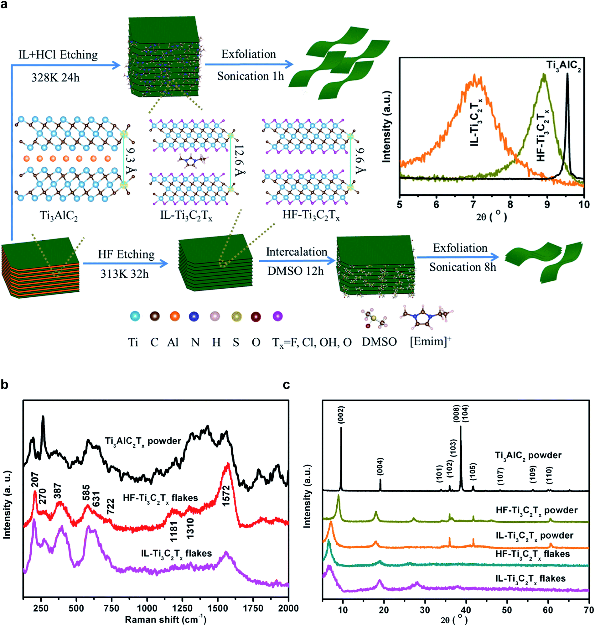 | ||
| Fig. 1 Synthesis of Ti3C2Tx flakes using IL + HCl or HF as etchants. (a) Illustration of IL + HCl and HF etching routes from Ti3AlC2 to Ti3C2Tx powders and nanoflakes, respectively. The inset shows the shifts of the (002) diffraction peak. (b) XRD patterns. (c) Raman spectra. | ||
The successful etching of Ti3AlC2 was confirmed from X-ray diffraction (XRD) data of samples, which were dried in a vacuum oven at 353 K for 24 h prior to measurements (Fig. 1b). The hot pressing sintering of the Ti, Al, and C powder mixture at 1773 K for 1 h resulted in an XRD pattern consistent with the Ti3AlC2 phase.39,40 After etching by the IL–HCl or HF, the removal of Al element layers is indicated by the XRD patterns of Ti3C2Tx powders with the disappearance of the reflections of the (008) and (104) facets of Ti3AlC2.1 The (002) diffraction peak of Ti3AlC2 at 9.6° broadens and shifts to 8.9° and 7.0°, and correspondingly the d spacing increases by 0.6 Å and 3.3 Å, respectively, for HF-Ti3C2Tx and IL-Ti3C2Tx powders. The larger c-lattice in IL-Ti3C2Tx powder is attributed to the bigger [Emim]+ cations that are in situ confined in the MXene interlayers during the etching processes. After ultrasonic exfoliation of the powders, the (002) peaks further shift to 6.5° and 6.7°, and the non-basal peak at 60° disappears in the patterns of IL-Ti3C2Tx and HF-Ti3C2Tx flakes due to the loss of long range ordered stacking (inset in Fig. 1a).
For the optical characteristics of the as-prepared Ti3C2Tx flakes in water, the good dispersibility is reflected by the Tyndall effect as a green laser beam passes through the colloidal solution (Fig. S1†). The high purity of the desired product is indicated by the absorption of Ti3C2Tx at 764 nm in the UV-visible spectra (Fig. S2†).41 Furthermore, the delaminated Ti3C2Tx is identified by the A1g out-of-plane symmetry vibrations of Ti and C atoms at 207 (ω1) and 722 (ω2) cm−1, along with Eg in-plane vibrations of Ti, C and terminal group atoms at 270 (ω4), 387 (ω4), 585 (ω5) and 631 (ω3) cm−1 in the Raman spectra (Fig. 1c).22,42–44 The bands in the spectral range of 1200–1690 cm−1 result from the carbide-derived carbon in Ti3C2Tx flakes,45,46 where the G band at 1572 cm−1 is associated with the highly ordered carbide, and the D and D4 bands, respectively, at 1310 and 1181 cm−1 are related to the disordered carbide. The high relative intensity of the G band and the unidentifiable D and D4 bands indicate that the reported mild IL–HCl etching can produce almost intact Ti3C2Tx flakes as compared with the harsh HF etching.
Depending on the etching protocols, the Ti3C2Tx flakes take on different morphologies and stacking patterns as observed from the transmission electron microscope (TEM) and scanning electron microscope (SEM) images. The IL-Ti3C2Tx flakes exhibit an almost transparent monolayer appearance with a larger average lateral size of 0.45 μm, and no obvious defects or oxidation is observed from their surfaces (Fig. 2a, S3 and S4†). However, the HF-Ti3C2Tx flakes present few layers with high-contrast images and an average lateral size of 0.18 μm (Fig. 2b and S5†). The pore defects and black TiO2 particles can be found from the surfaces of HF-Ti3C2Tx flakes (Fig. S6†), indicating that the flakes are subjected to damage and oxidation during strong HF etching and long-time delamination.47 After the suspension solutions are naturally dried at room temperature, the collected SEM images show that the IL-Ti3C2Tx flakes can self-assemble into a 3D architecture with large interlayer spaces owing to the pillar effects of [Emim]+ ions (Fig. 2c), while the restacked HF-Ti3C2Tx flakes display the close packing appearance (Fig. 2d). Beyond those differences, the same chemical structures of IL-Ti3C2Tx and HF-Ti3C2Tx flakes make them have similar selected area electron diffraction (SEAD) patterns and high-resolution TEM (HRTEM) images, giving Ti3C2Tx a hexagonal arrangement crystal phase and an interplanar spacing of 2.649 Å for the (1![[1 with combining macron]](https://www.rsc.org/images/entities/char_0031_0304.gif) 01) lattice plane (Fig. 2e and f).48 Moreover, the single IL-Ti3C2Tx flake is found to have an average thickness of 2.5 nm from atomic force microscope (AFM) analysis (Fig. 2g). Obviously, the IL–HCl etching is a mild strategy to produce the monolayer Ti3C2Tx MXene with relatively larger size and low oxidation. Particularly, [Emim]+ ions pillar the large interlamellar spaces of IL-Ti3C2Tx flakes, and provide effective channels for ions to fully access the electrochemically active sites in energy storage and conversion.
01) lattice plane (Fig. 2e and f).48 Moreover, the single IL-Ti3C2Tx flake is found to have an average thickness of 2.5 nm from atomic force microscope (AFM) analysis (Fig. 2g). Obviously, the IL–HCl etching is a mild strategy to produce the monolayer Ti3C2Tx MXene with relatively larger size and low oxidation. Particularly, [Emim]+ ions pillar the large interlamellar spaces of IL-Ti3C2Tx flakes, and provide effective channels for ions to fully access the electrochemically active sites in energy storage and conversion.
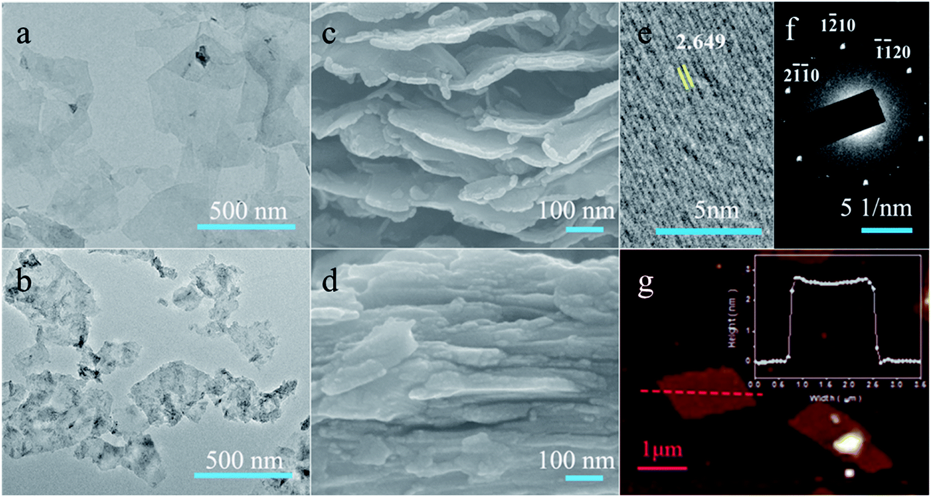 | ||
| Fig. 2 Morphologies of Ti3C2Tx nanoflakes. (a–d) TEM and SEM images were respectively taken from IL-Ti3C2Tx (a and c) and HF-Ti3C2Tx (b and d) flakes. (e and f) SAED patterns (e) and HRTEM images (f) of IL-Ti3C2Tx flakes. (g) AFM images of IL-Ti3C2Tx flakes; the inset shows the height profile along the red dashed line. | ||
3.2 Ionic–electronic coupling of [Emim]+ with Ti3C2Tx flakes
Energy-dispersive spectroscopy (EDS) revealed that the IL-Ti3C2Tx flakes consist of C, N, O, F, Cl and Ti elements, and as expected, no Al element is detected owing to the selective etching strategy of complete removal of Al layers (Fig. S7 and Table S1†). The atomic ratio of Ti to C at about 1.5:1 demonstrates that the basal structure of Ti3C2 was preserved during the mild etching, and the content of the introduced [Emim]+ cations reaches 1.96 wt% in the IL-Ti3C2Tx flakes, giving a mole ratio of Ti3C2 units to [Emim]+ ions of about 27:1. It follows that the as-prepared IL-Ti3C2Tx flakes could be denoted as [Emim]0.037Ti3C2Om(OH)xClyF0.222.
Thermodynamically, the stability of IL-Ti3C2Tx flakes can be described by the adsorption energies (Eads) of Ti3C2Tx flakes toward [Emim]+ cations, which are mainly dominated by the terminal groups. The Eads of [Emim]+ between two monolayers is respectively calculated from Ti3C2F2, Ti3C2O2 and Ti3C2(OH)2 using DFT, and the optimized configurations of [Emim]+–Ti3C2F2 and [Emim]+–Ti3C2O2 models are depicted in Fig. S8.† The Eads values are −0.48 in [Emim]+–Ti3C2F2 and −0.52 eV in [Emim]+–Ti3C2O2, indicating the strong interactions of [Emim]+ with Ti3C2Tx. In contrast, Bader charge analysis shows that the hydrogen surfaces of Ti3C2(OH)2 hold positive charge due to the high electronegativity of O atoms (Table S2†), and very weakly interact with the cations. Moreover, the charge density differences are studied to understand the charge transfer and adsorption energy (Fig. 3a and b). As compared with [Emim]+–Ti3C2O2, interestingly, it is noted that the much stronger coupling of [Emim]+ with Ti3C2F2 causes the sub-surface Ti atoms to be involved in interactive charge transfer. In this situation, the confined [Emim]+ cations can integrate Ti3C2F2 flakes into a coupled electronic conductor through both F terminations and Ti element layers.
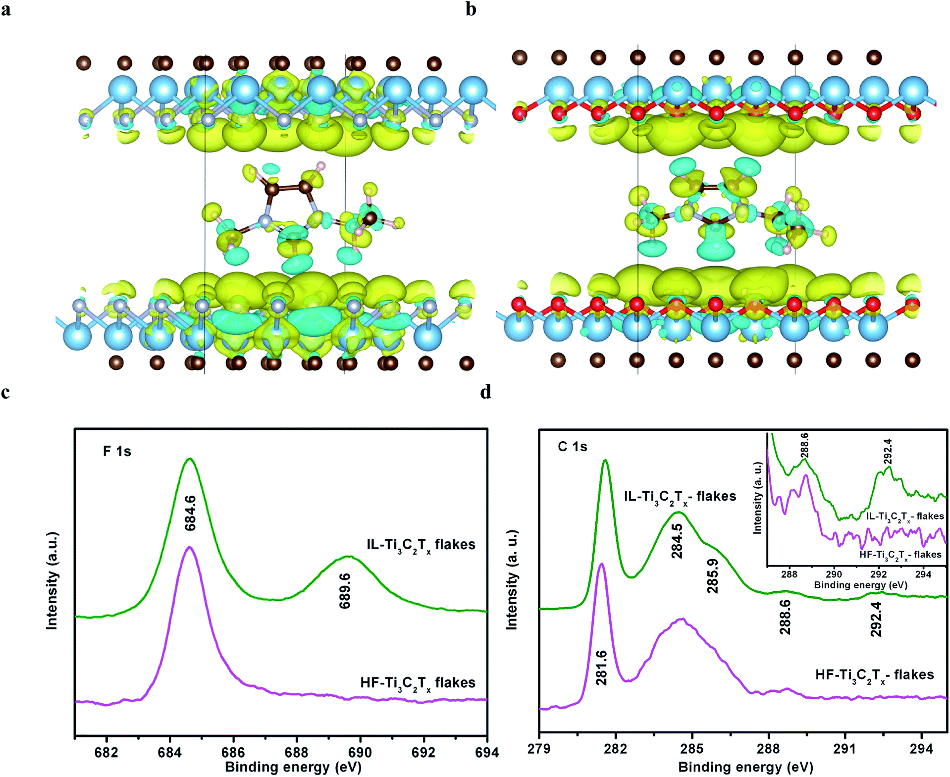 | ||
| Fig. 3 (a and b) Charge density difference (Δρ = ρtot − ρ[Emim]+ − ρTi3C2Tx) of the [Emim]+–Ti3C2F2 (a), and [Emim]+–Ti3C2O2 (b). The d spacing is set at 12.6 Å, and the yellow and green represent electron accumulation and depletion. The blue, brown, magenta, red and dark grey balls respectively denote Ti, C, H, O and F atoms. (c and d) Chemical states in Ti3C2Tx flakes of F 1s (c) and C 1s (d). The inset is a magnification of the high binding energy region. | ||
The charge density differences indicate the significant interactions of H3O+ with Ti3C2F2 or Ti3C2O2 (Fig. S9†); hence, H3O+ could be a powerful competitor against the coupling of [Emim]+ with Ti3C2Tx flakes during in situ anchoring of the cations in the aqueous IL–HCl medium. However, it is shown that Eads (−0.35 eV) in H3O+–Ti3C2F2 is lower than that in [Emim]+–Ti3C2F2, making it difficult to prevent the coupling of [Emim]+ with Ti3C2F2. On the other hand, H3O+ can participate in the charge transfer on Ti3C2O2 owing to the Eads (−0.46 eV) in H3O+–Ti3C2O2 similar to that in [Emim]+–Ti3C2O2. It is the terminal F, rather than terminal O, that acts as the leading agent in the ionic–electronic coupling in [Emim]+–Ti3C2Tx. Moreover, the confined [Emim]+ cations hardly curb the electrochemical activities of O and OH terminations as these active sites react reversibly with H3O+.
The strong coupling is supported by X-ray photoelectron spectroscopy (XPS) analysis. In the high-resolution XPS spectra, the N 1s, Cl 2p, O 1s, and Ti 2p peaks are respectively ascribed to N–C/NC (401.8 eV), Cl–Ti (198.8 and 200.5 eV), O/hydroxides–Ti (529.5 and 532.0 eV), and Ti–C (455.0 and 461.0 eV) in IL-Ti3C2Tx flakes (Fig. S10†). Because the [Emim]+ cations protect the flakes from being oxidized, no peak of TiO2 at 458.5 eV is detected from IL-Ti3C2Tx flakes,49 in accordance with the TEM observations which indicate the absence of TiO2 particles. These chemical states suggest that the Cl, O and OH terminations chemically combine with Ti3C2 flakes, and are hardly involved in the ionic–electronic interactions of [Emim]+ with Ti3C2Tx in IL-Ti3C2Tx flakes. Compared with HF-Ti3C2Tx flakes, impressively, IL-Ti3C2Tx flakes display two new XPS peaks of C–Fn (n = ∼2) at 689.6 and 292.4 eV, respectively, in F 1s and C 1s high-resolution spectra, in addition to the familiar peaks of Ti–F (684.6 eV), Ti–C (281.6 eV), C–C (284.5 eV), C–O/C–N (285.9 eV), and CO/CN (288.6 eV) (Fig. 3c and d). Clearly, it is the F terminations with the greatest electronegativity that chemically integrate [Emim]+ cations into Ti3C2Tx flakes through the strong coupled charge transfers (Table S2†). The availability of terminal F, which couples with [Emim]+ ions, is estimated from the integral area of the C–Fn peak, and accounts for 41.6% of the overall area of F 1s peaks in IL-Ti3C2Tx flakes.
3.3 Electronic and structural characteristics of the coupled conductor
The surface electronic characteristics are controlled by the surface geometric structure and chemical properties, and reflected by the projected density of states (PDOS). In [Emim]+–Ti3C2O2, the peaks of the occupied orbitals of [Emim]+ more closely match the PDOS of surface O atoms, indicating the strong orbital interactions of terminal O with [Emim]+ (Fig. S11†). Before and after [Emim]+ is confined in Ti3C2O2 interlayers, the almost unchanged PDOS of Ti atoms implies that the metal layers are not involved in the electron transfer between O terminations and [Emim]+ (Fig. 4a). Moreover, the separation of valence and conduction bands presents the coupled [Emim]+–Ti3C2O2 as a semiconductor with a band gap of 0.83 eV.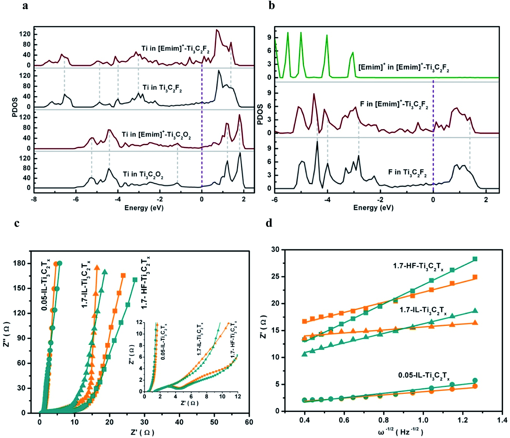 | ||
| Fig. 4 (a) PDOS of Ti atoms respectively from Ti3C2O2, [Emim]+–Ti3C2O2, Ti3C2F2, and [Emim]+–Ti3C2F2. (b) PDOS of F atoms from Ti3C2F2, and F atoms and [Emim]+ from [Emim]+–Ti3C2F2. The Fermi levels are set to zero. (c) Nyquist plots of 0.05-IL-Ti3C2Tx/GCE (●), 1.7-IL-Ti3C2Tx/GCE (◄), and 1.7-HF-Ti3C2Tx/GCE (■) in the mixed electrolyte measured at −0.3 V (orange) and −0.9 V (cyan), respectively. The inset is a magnification of the high-frequency region. (d) Linearly fitted graph of Z′ against ω−1/2 in the low-frequency region of Nyquist plots. | ||
After [Emim]+ is implanted into Ti3C2F2 interlayers, however, the PDOS of Ti and F atoms exhibits negative and positive shifts, respectively, below and above the Fermi level (EF), indicating that the ionic–electronic coupling contributes to the stabilization toward [Emim]+–Ti3C2F2 (Fig. 4a and b). Notably, the orbital hybridization enhances the electron states of Ti and F atoms near EF, and imparts [Emim]+–Ti3C2F2 to the electron conductor with a metal-like band structure. It is accepted that the coupling of the nonmetal cations with terminal F bridges the electron transfer between two Ti element layers, and improves the electrochemical activity of Ti3C2Tx flakes.
The kinetics of ion/charge transport depend on the IL-Ti3C2Tx microstructure, and can be estimated by electrochemical impedance measurements. The glassy carbon electrode (GCE) was loaded with 1.7 mg cm−2 Ti3C2Tx flakes, respectively, to prepare 1.7-IL-Ti3C2Tx/GCE and 1.7-HF-Ti3C2Tx/GCE. The Nyquist plots of the resultant electrodes were measured in 3 M H2SO4–0.8 M [Emim]HSO4 electrolyte, and the applied reducing potentials are 0.3 V and 0.9 V which are respectively related to the electric double layer and the surface redox reactions (Fig. 4c). The intercepts on the real axis stand for series resistances (Rs) less than 2 Ω due to high ionic and electronic conductivities in the electrochemical systems. In the high-frequency region, the ionic–electronic coupling gives 1.7-IL-Ti3C2Tx an indiscernible arc along the real axis. This implies a very low faradaic charge-transfer resistance (Rct) via the electron transport promoted by the confined [Emim]+ ions in the electrode reaction. Without the assistance of the confined [Emim]+ ions, in contrast, the 1.7-HF-Ti3C2Tx displays an identifiable arc and the highest Rct.
To evaluate the Warburg diffusion resistance of ion transport in the Ti3C2Tx electrodes, the Warburg coefficient (σ) is obtained from the slope in the plot of Z′ against ω−1/2 (ω = 2πf) in the low-frequency region (Fig. 4d). The σ of 1.7-HF-Ti3C2Tx is 12.7 at −0.3 V and increases to 17.6 at −0.9 V, while 1.7-IL-Ti3C2Tx presents σ of 2.7 and 8.8, respectively, at −0.3 V and −0.9 V. The smaller σ signifies the lower diffusion resistance of ions, and 1.7-IL-Ti3C2Tx/GCE has the faster kinetics of ion diffusion and faradaic charge-transfer than 1.7-HF-Ti3C2Tx/GCE, giving more proof that the confined [Emim]+ cations assist charge/ion transport. The much lower σ in 1.7-IL-Ti3C2Tx implies that the anchored [Emim]+ ions can self-assemble the 2D nanosheets into an electrochemically stable and ionophilic 3D framework through the spontaneous π–π stacking of the coupled imidazole rings, as observed from the SEM images (Fig. 2c). In the IL-Ti3C2Tx bulk, it is recognized that the pillar effect of the confined [Emim]+ ions creates a larger interlayer space as verified by XRD patterns (Fig. 1b), and induces interconnected paths to fulfil the more efficient transport of electroactive species for reversible electrochemical reduction/oxidation.
The pillar effect is supported by the properties of 0.05-IL-Ti3C2Tx/GCE with a very low IL-Ti3C2Tx loading of 0.05 mg cm−1, which minimizes the ion transport limitations. It is shown that the resultant electrode has a capacitance of 603 F g−1 at 2 mV s−1 (Fig. S12†), a value only 12.7% higher than the 535 F g−1 for 1.7-IL-Ti3C2Tx/GCE. The σ of 0.05-IL-Ti3C2Tx/GCE, respectively, is 2.9 at −0.3 V and 4.1 at −0.9 V (Fig. 4d), indicating a similar Warburg diffusion resistance to that of 1.7-IL-Ti3C2Tx/GCE. Although the IL-Ti3C2Tx loading decreases 34 fold on the GCE, the capacitance and σ of 0.05-IL-Ti3C2Tx are comparable with those of 1.7-IL-Ti3C2Tx, and suggest that the confined [Emim]+ ions pillar the large interlayer space to provide efficient tunnels for ion transport and access to the electrochemically active sites. Evidently, the unique electronic and structural characteristics of the resultant conductor result from a single ionic species that is integrated into Ti3C2Tx interlayers through the strong coupling of [Emim]+ ions with F terminations. Consequently, the coupled conductor without the overscreening effect is expected to exhibit high efficiencies in electrochemical energy storage and conversion.
3.4 Capacitance performances of IL-Ti3C2Tx flakes
The capacitance performances of 1.7-IL-Ti3C2Tx/GCE and 1.7-HF-Ti3C2Tx/GCE were estimated in an aqueous solution of 3 M H2SO4 or mixed aqueous electrolytes of 3 M H2SO4–1-ethyl-3-methylimidazolium hydrosulfate ([Emim]HSO4). Aiming to counterbalance the possible loss of the confined [Emim]+ ions during charge–discharge operations, here, [Emim]HSO4 is selected as the supporting electrolyte containing the same ions as the anchored cations in interlayers and the free anions in solution. It is shown that the [Emim]HSO4 concentrations exert good effects on the capacitances of 1.7-IL-Ti3C2Tx/GCE in the mixed aqueous electrolytes (Fig. S13†). The capacitances increase with increasing the IL content owing to the wide potential window and stabilization to the confined [Emim]+ cations, while the capacitance decrease is attributed to the increase of mixed-electrolyte viscosity as the IL content is more than 0.8 M. Particularly, the high Eads (−0.88 eV) between [Emim]+ and HSO4− makes them readily associate into ion pairs, if the cations, always accompanied by the anions, are preintercalated or electrically driven into Ti3C2Tx interlayers. The ion pairs weakly interact with Ti3C2Tx flakes, cannot dissociate the coupling of [Emim]+ with F terminations (Eads = −0.52 eV), and hardly affect the electrochemical properties of IL-Ti3C2Tx. The is verified by the capacitances of 1.7-HF-Ti3C2Tx/GCE that do not benefit from the different pretreatments as shown by the cyclic voltammogram (CV) profiles in 3 M H2SO4–0.8 M [Emim]HSO4 electrolyte (Fig. S14†).In the CV profile of 1.7-IL-Ti3C2Tx/GCE in 3 M H2SO4, the anodic and cathodic peaks, respectively, appear at −0.79 and −0.82 V with a small potential difference of 0.03 V, and give peak currents of 0.18 and 0.19 mA with a ratio of about 1, indicating reversible electrochemical reduction/oxidation (Fig. 5a). Because the electrochemical sites of terminal O and OH are not shielded by the confined [Emim]+ cations, the redox originates from the reaction of terminal O with hydronium ions through bonding/debonding in acid medium:50
| [Emim]0.037Ti3C2Om(OH)xClyF0.222 + δH+ + δe− ⇔ [Emim]0.037Ti3C2Om−δ(OH)x+δClyF0.222 | (4) |
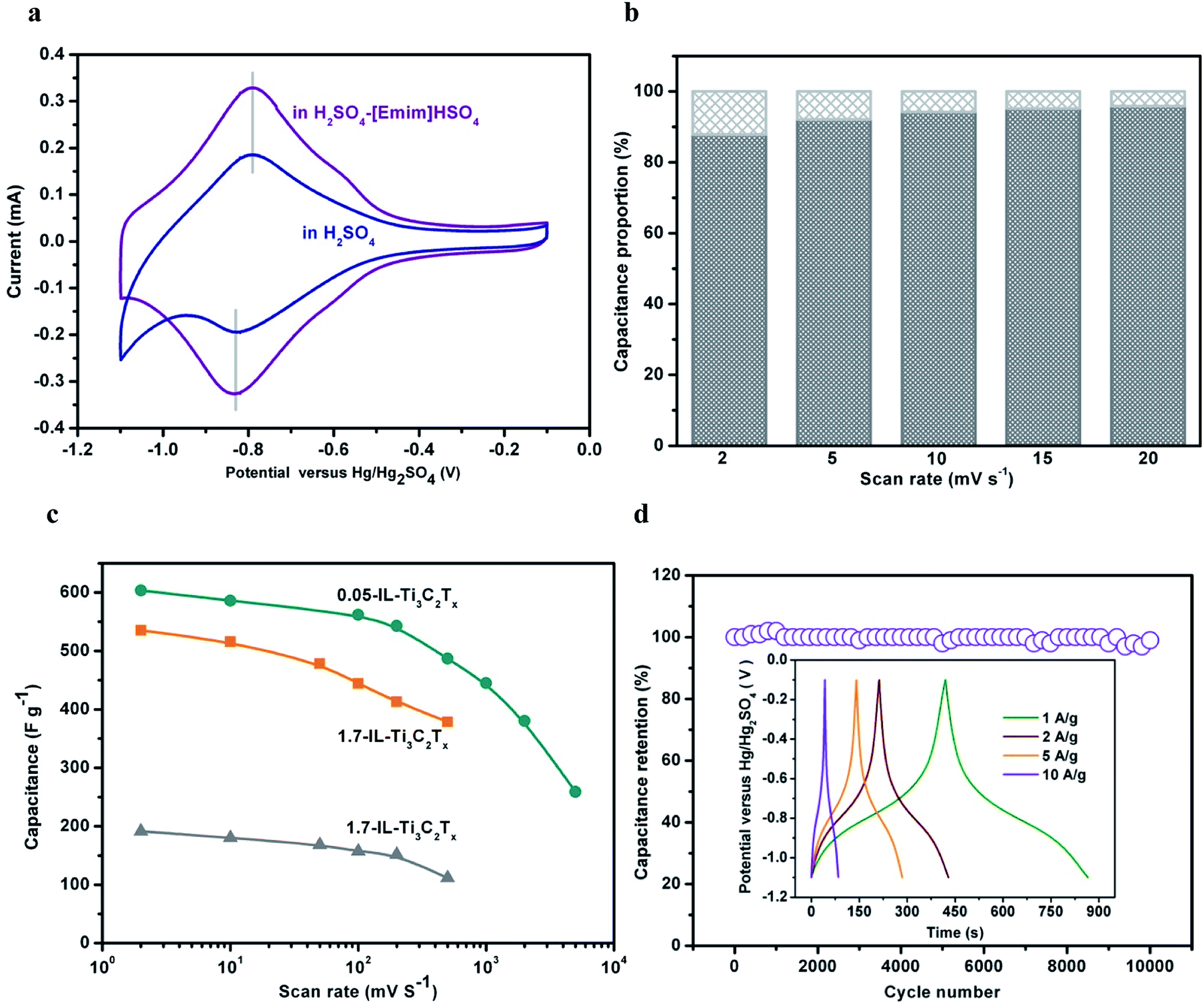 | ||
| Fig. 5 (a) CVs of 1.7-IL-Ti3C2Tx/GCE recorded at 2 mV s−1 in 3 M H2SO4 and 3 M H2SO4–0.8 M [Emim]HSO4, respectively. (b) Proportion of the surface-controlled capacitance (dark grey) and the intercalation capacitance (light grey) for 1.7-IL-Ti3C2Tx at different υ. (c) Rate performance of gravimetric capacitance, respectively, for 1.7-HF-Ti3C2Tx/GCE, 1.7-IL-Ti3C2Tx/GCE, and 0.05-IL-Ti3C2Tx/GCE in 3 M H2SO4–0.8 M [Emim]HSO4. (d) Cyclability of 1.7-IL-Ti3C2Tx/GCE in the mixed electrolyte at 5 A g−1. The inset shows GCD curves at different discharging current densities. | ||
Although 1.7-IL-Ti3C2Tx/GCE displays a similar CV profile in the mixed electrolyte, the potential window of acid electrolyte is widened from 0.83 V in 3 M H2SO4 to 1.00 V in 3 M H2SO4–0.8 M [Emim]HSO4 electrolyte. Correspondingly, the gravimetric capacitance increases from 262 F g−1 in 3 M H2SO4 to 535 F g−1 in 3 M H2SO4–0.8 M [Emim]HSO4, where the latter is 104.2% more than that in 3 M H2SO4 over their respective potential windows.
To clarify the roles played by the confined [Emim]+ ions, the confined [Emim]+-free 1.7-HF-Ti3C2Tx/GCE is employed as the relative reference. Although the CVs of 1.7-HF-Ti3C2Tx/GCE show almost the same peak currents, the nonpolarized potential windows extend from 0.83 V in 3 M H2SO4 to 0.93 V in 3 M H2SO4–0.8 M [Emim]HSO4, despite being a little narrower than that of 1.7-IL-Ti3C2Tx/GCE (Fig. S15†). Resultantly, the gravimetric capacitance in 3 M H2SO4–0.8 M [Emim]HSO4 is only 30.7% higher than that in 3 M H2SO4. In the mixed electrolyte, therefore, the capacitance enhancement of 1.7-IL-Ti3C2Tx/GCE is derived from two contributions: the potential window extension owing to the [Emim]+ ions in solution, and the redox reaction promotion owing to the confined [Emim]+ ions in interlayers. It is shown that the confined [Emim]+ ions have stronger effects on the capacitance than the free [Emim]+ ions.
The outstanding performances of 1.7-IL-Ti3C2Tx/GCE are inherent to the chemically anchored [Emim]+ ions without the overscreening charge effect. In this regard, the confined [Emim]+ ions act as the catalyzer to transfer the charge efficiently, and put up the pillar effect to rapidly transport the ions in the reversible electrochemical reactions. The peak current (ip) in CVs and υ follow the exponential relationship i = aυb, where a and b are variables. From the slope of logipversus logυ (Fig. S16†), the b value for 1.7-IL-Ti3C2Tx/GCE approximately equals to 1, implying charge storage through the mechanism of surface-controlled capacitance. Furthermore, the contribution of surface-controlled capacitance is quantified from the different storage mechanisms in the IL-Ti3C2Tx. Generally, the capacity is a combination of surface-controlled capacitance (k2υ: EDLC and pseudocapacitance) and diffusion-controlled capacitance (k1υ1/2: intercalation pseudocapacitance), and the current (i) at a given potential is expressed as a function of υ:51,52
| i (V) = k1υ1/2 + k2υ | (5) |
| i (V)/υ1/2 = k1 + k2υ1/2 | (6) |
Fig. 5b and S18† show the percentage profile from the two capacitance contributions. The surface-controlled capacitance accounted for 94% of the total capacitance at 10 mV s−1, and even for 88% at 2 mV s−1. It was evident that the electrochemical energy storage of IL-Ti3C2Tx is dominated by surface-controlled pseudocapacitance, while the intercalation pseudocapacitance only shares a small fraction that remains almost unvaried during charging and discharging cycles. Hence, the capacitance enhancement of the ionic–electronic coupling is mainly derived from the confined [Emim]+ ions to catalyze the faradaic surface-charge transfer (eqn (4)).
Besides the increase in gravimetric capacitances, the confined [Emim]+ ions impart good rate performance, high cyclability and coulombic efficiency to the coupled IL-Ti3C2Tx conductor. Therefore, the coupled conductor demonstrates high reaction reversibility and structural stability in 3 M H2SO4–0.8 M [Emim]HSO4. The gravimetric capacitances are determined from CVs at scan rates (υ) from 2 to 500 mV s−1 (Fig. 5c, S19 and S20†). As the scan rate varies from 2 to 500 mV s−1, the capacity of 1.7-IL-Ti3C2Tx/GCE decreases from 535 to 378 F g−1 with 70.6% retention, while the capacity of 1.7-HF-Ti3C2Tx/GCE decreases from 191 to 111 F g−1 with 58.1% retention. It is noted that the capacitances of 1.7-IL-Ti3C2Tx/GCE in the mixed electrolyte surpass those of most known Ti3C2Tx-based materials (Table S3†), indicating the critical role played by the confined [Emim]+ ions in the capacitive enhancement. Moreover, the reversible reactions and stable structure in the electrode mean that the capacitance is hardly degraded after 10000 cycles operated at 5 A g−1 (Fig. 5d). The coulombic efficiencies are almost 100% at different discharging current densities, as illustrated from the symmetrical profiles of galvanostatic charge–discharge (GCD) curves of 1.7-IL-Ti3C2Tx/GCE.
Evidently, the chemically confined [Emim]+ cations are different from those ions that are physically intercalated or adsorbed into the 2D nanosheets, and become of more importance for achieving enhanced electrochemical properties. The promoting mechanisms include the following: (i) the ionic–electronic coupling can integrate single ionic species into Ti3C2Tx flakes without counterions, and banish the undesired overscreening charge effect from the electrified interfaces; (ii) [Emim]+ ions can couple with Ti3C2Tx flakes through terminal F, and activate the “inert” F terminations, but not lay restraints on the electroactive O and OH terminations; (iii) the band edge of DOS near EF can mediate the electron transport out of or into metal-like Ti3C2Tx flakes, and promote the surface redox reactions; (iv) the coupled [Emim]+ ions bear the more positive charges, and enrich H3O+ ions through stronger hydrogen bonding; (v) the pillar effect of the confined [Emim]+ ions offers large ionophilic interlayers favorable for ion diffusion along the Ti3C2Tx interfaces.
4. Conclusions
The IL–HCl etchant was successfully employed to produce Ti3C2Tx nanoflakes with larger lateral size, fewer defects, and oxidation-free surfaces. Under mild conditions, the delamination and intercalation were completed in a single step, and the exfoliation of the Ti3C2Tx bulk was achieved by simple handshaking or short-time sonication, instead of the HF-etching process of additional intercalation and time-consuming post treatment. In particular, XPS analysis and DFT calculations show the strong coupling of [Emim]+ ions with electronic Ti3C2Tx flakes through the F terminations, in which the utilization efficiency of terminal F reaches 41.6%. It is the strong coupling that can in situ confine [Emim]+ ions into Ti3C2Tx interlayers to produce the metal-like coupled conductor without the overscreening charge effect. The chemically anchored [Emim]+ ions can arouse the “inert” terminal F, accelerate electron and ion transport, self-assemble the ionophilic nanoflakes with a 3D architecture to favor ion access to electroactive sites, and catalyze the surface redox reactions. Resultantly, 1.7-IL-Ti3C2Tx and 0.05-IL-Ti3C2Tx in the 3 M H2SO4–0.8 M [Emim]HSO4 mixed solution, respectively, exhibited excellent gravimetric capacitances of 535 and 603 F g−1 at 2 mV s−1, almost independent of the thickness of IL-Ti3C2Tx. This study advances a new strategy to build mixed conductors through the coupling of nonmetal ions with 2D nanosheets, and to control their electrochemical activity in supercapacitors, batteries, electrocatalysts, electrosensors, etc.Conflicts of interest
There are no conflicts to declare.Acknowledgements
This work is supported by the National Natural Science Foundation of China (21573059 and U1704251), and by the “111” Project (no. D17007).Notes and references
- M. Naguib, M. Kurtoglu, V. Presser, J. Lu, J. J. Niu, M. Heon, L. Hultman, Y. Gogotsi and M. W. Barsoum, Adv. Mater., 2011, 23, 4248 CrossRef CAS PubMed.
- A. E. Allah, J. Wang, Y. V. Kaneti, T. Li, A. A. Farghali, M. H. Khedr, A. K. Nanjundan, B. Ding, H. Dou, X. G. Zhang, B. Yoshio and Y. Yamauchi, Nano Energy, 2019, 65, 103991 CrossRef CAS.
- W. Q. Tian, A. VahidMohammadi, Z. Wang, L. Q. Ouyang, M. Beidaghi and M. M. Hamedi, Nat. Commun., 2019, 10, 1 CrossRef PubMed.
- S. Kajiyama, L. Szabova, K. Sodeyama, H. Iinuma, R. Morita, K. Gotoh, Y. Tateyama, M. Okubo and A. Yamada, ACS Nano, 2016, 10, 3334 CrossRef CAS PubMed.
- B. Anasori, M. R. Lukatskaya and Y. Gogotsi, Nat. Rev. Mater., 2017, 2, 16098 CrossRef CAS.
- J. Li, X. T. Yuan, C. Lin, Y. Q. Yang, L. Xu, X. Du, J. L. Xie, J. H. Lin and J. L. Sun, Adv. Energy Mater., 2017, 7, 1602725 CrossRef.
- C. F. Zhang, B. Anasori, A. Seral-Ascaso, S. H. Park, N. McEvoy, A. Shmeliov, G. S. Duesberg, J. N. Coleman, Y. Gogotsi and V. Nicolosi, Adv. Mater., 2017, 29, 1702678 CrossRef PubMed.
- L. Ding, Y. Y. Wei, Y. J. Wang, H. B. Chen, J. Caro and H. H. Wang, Angew. Chem., 2017, 129, 1851 CrossRef.
- L. S. Huang, X. L. Gu and G. F. Zheng, Chem, 2020, 5, 9 Search PubMed.
- X. H. Xie, S. G. Chen, W. Ding, Y. Nie and Z. D. Wei, Chem. Commun., 2013, 49, 10112 RSC.
- H. Liu, C. Y. Duan, C. H. Yang, W. Q. Shen, F. Wang and Z. F. Zhu, Sens. Actuators, B, 2015, 218, 60 CrossRef CAS.
- M. Q. Zhao, C. E. Ren, Z. Ling, M. R. Lukatskaya, C. F. Zhang, K. L. V. Aken, M. W. Barsoum and Y. Gogotsi, Adv. Mater., 2015, 27, 339 CrossRef CAS PubMed.
- D. B. Xiong, X. F. Li, Z. M. Bai and S. G. Lu, Small, 2018, 14, 1703419 CrossRef PubMed.
- B. Anasori, Y. Xie, M. Beidaghi, J. Lu, B. C. Hosler, L. Hultman, P. R. C. Kent, Y. Gogotsi and M. W. Barsoum, ACS Nano, 2015, 9, 9507 CrossRef CAS PubMed.
- M. R. Lukatskaya, O. Mashtalir, C. E. Ren, Y. Dall'Agnese, P. Rozier, P. L. Taberna, M. Naguib, P. Simon, M. W. Barsoum and Y. Gogotsi, Science, 2013, 341, 1502 CrossRef CAS PubMed.
- M. Naguib, V. N. Mochalin, M. W. Barsoum and Y. Gogotsi, Adv. Mater., 2014, 26, 992 CrossRef CAS PubMed.
- M. Alhabeb, K. Maleski, B. Anasori, P. Lelyukh, L. Clark, S. Sin and Y. Gogotsi, Chem. Mater., 2017, 29, 7633 CrossRef CAS.
- M. R. Lukatskaya, S. Kota, Z. F. Lin, M. Q. Zhao, N. Shpigel, M. D. Levi, J. Halim, P. L. Taberna, M. W. Barsoum, P. Simon and Y. Gogotsi, Nat. Energy, 2017, 2, 17105 CrossRef CAS.
- X. P. Mu, D. S. Wang, F. Du, G. Chen, C. Z. Wang, Y. J. Wei, Y. Gogotsi, Y. Cao and Y. Dall'Agnese, Adv. Funct. Mater., 2019, 29, 1902953 CrossRef.
- O. Mashtalir, M. Naguib, B. Dyatkin, Y. Gogotsi and M. W. Barsoum, Mater. Chem. Phys., 2013, 139, 147 CrossRef CAS.
- M. Naguib, R. R. Unocic, B. L. Armstrong and J. Nanda, Dalton Trans., 2015, 44, 9353 RSC.
- M. M. Hu, T. Hu, Z. J. Li, Y. Yang, R. F. Cheng, J. X. Yang, C. Cui and X. H. Wang, ACS Nano, 2018, 12, 3578 CrossRef CAS PubMed.
- M. Naguib, J. Halim, J. Lu, K. M. Cook, L. Hultman, Y. Gogotsi and M. W. Barsoum, J. Am. Chem. Soc., 2013, 135, 15966 CrossRef CAS PubMed.
- M. Ghidiu, M. R. Lukatskaya, M. Q. Zhao, Y. Gogotsi and M. W. Barsoum, Nature, 2014, 516, 78 CrossRef CAS PubMed.
- M. Boota and Y. Gogotsi, Adv. Energy Mater., 2019, 9, 1802917 CrossRef.
- L. Yang, W. Zheng, P. Zhang, J. Chen, W. Zhang, W. B. Tian and Z. M. Sun, Electrochim. Acta, 2019, 300, 349 CrossRef CAS.
- Q. Tang, Z. Zhou and P. W. Shen, J. Am. Chem. Soc., 2012, 134, 16909 CrossRef CAS PubMed.
- T. F. Li, L. L. Yao, Q. L. Liu, J. J. Gu, R. C. Luo, J. H. Li, X. D. Yan, W. Q. Wang, P. Liu, B. Chen, W. Zhang, W. Abbas, R. Naz and D. Zhang, Angew. Chem., Int. Ed., 2018, 57, 6115 CrossRef CAS PubMed.
- J. Halim, M. R. Lukatskaya, K. M. Cook, J. Lu, C. R. Smith, L. Å. Näslund, S. J. May, L. Hultman, Y. Gogotsi, P. Eklund and M. W. Barsoum, Chem. Mater., 2014, 26, 2374 CrossRef CAS PubMed.
- M. V. Fedorov and A. A. Kornyshev, Chem. Rev., 2014, 114, 2978 CrossRef CAS PubMed.
- S. G. Zhang, J. H. Zhang, Y. Zhang and Y. Q. Deng, Chem. Rev., 2017, 117, 6755 CrossRef CAS PubMed.
- F. Buchner, K. Forster-Tonigold, M. Bozorgchenani, A. Gross and R. J. Behm, J. Phys. Chem. Lett., 2016, 7, 226 CrossRef CAS PubMed.
- J. Vatamanu, O. Borodin and G. D. Smith, J. Am. Chem. Soc., 2010, 132, 14825 CrossRef CAS PubMed.
- J. Comtet, A. Niguès, V. Kaiser, B. Coasne, L. Bocquet and A. Siria, Nat. Mater., 2017, 16, 634 CrossRef CAS PubMed.
- J. Huang, B. G. Sumpter and V. Meunier, Angew. Chem., Int. Ed., 2008, 47, 520 CrossRef CAS PubMed.
- C. Merlet, B. Rotenberg, P. A. Madden, P. Taberna, P. Simon, Y. Gogotsi and M. Salanne, Nat. Mater., 2012, 11, 306 CrossRef CAS PubMed.
- M. Naguib, O. Mashtalir, J. Carle, V. Presser, J. Lu, L. Hultman, Y. Gogotsi and M. W. Barsoum, ACS Nano, 2012, 6, 1322 CrossRef CAS PubMed.
- V. M. Hong Ng, H. Huang, K. Zhou, P. S. Lee, W. X. Que, J. Z. Xu and L. B. Kong, J. Mater. Chem. A, 2017, 5, 3039 RSC.
- X. H. Wang and Y. C. Zhou, J. Mater. Sci. Technol., 2010, 26, 385 CrossRef CAS.
- A. G. Zhou, C. Wang and Y. Huang, Mater. Sci. Eng., A, 2003, 352, 333 CrossRef.
- K. Maleski, V. N. Mochalin and Y. Gogotsi, Chem. Mater., 2017, 29, 1632 CrossRef CAS.
- J. Yan, C. E. Ren, K. Maleski, C. B. Hatter, B. Anasori, P. Urbankowski, A. Sarycheva and Y. Gogotsi, Adv. Funct. Mater., 2017, 27, 1701264 CrossRef.
- M. M. Hu, Z. J. Li, T. Hu, S. H. Zhu, C. Zhang and X. H. Wang, ACS Nano, 2016, 10, 11344 CrossRef CAS PubMed.
- L. Y. Xiu, Z. Y. Wang, M. Z. Yu, X. H. Wu and J. S. Qiu, ACS Nano, 2018, 12, 8017 CrossRef CAS PubMed.
- C. H. Yang, Y. Tang, Y. P. Tian and Y. Y. Luo, Adv. Energy Mater., 2018, 8, 1802087 CrossRef.
- C. H. Yang, W. X. Que, X. T. Yin, Y. P. Tian, Y. W. Yang and M. D. Que, Electrochim. Acta, 2017, 225, 416 CrossRef CAS.
- A. Lipatov, M. Alhabeb, M. R. Lukatskaya, A. Boson, Y. Gogotsi and A. Sinitskii, Adv. Electron. Mater., 2016, 2, 1600255 CrossRef.
- O. Mashtalir, M. Naguib, V. N. Mochalin, Y. Dall'Agnese, M. Heon, M. W. Barsoum and Y. Gogotsi, Nat. Commun., 2013, 4, 1 Search PubMed.
- C. E. Ren, M. Q. Zhao, T. Makaryan, J. Halim, M. Boota, S. Kota, B. Anasori, M. W. Barsoum and Y. Gogotsi, ChemElectroChem, 2016, 3, 689 CrossRef CAS.
- J. Wang, J. Polleux, J. Lim and B. Dunn, J. Phys. Chem. C, 2007, 111, 14925 CrossRef CAS.
- V. Augustyn, P. Simon and B. Dunn, Energy Environ. Sci., 2014, 7, 1597 RSC.
- M. Okubo, A. Sugahara, S. Kajiyama and A. Yamada, Acc. Chem. Res., 2018, 51, 591 CrossRef CAS PubMed.
Footnotes |
| † Electronic supplementary information (ESI) available: Chemicals, characterization methods, Fig. S1–S20, and Tables S1–S3. See DOI: 10.1039/d0ta09712h |
| ‡ F. Yan and C. Zhang contributed equally to this work. |
| This journal is © The Royal Society of Chemistry 2021 |