Exceptional interfacial solar evaporation via heteromorphic PTFE/CNT hollow fiber arrays†
Tiantian
Li
ad,
Qile
Fang
ab,
Jianqiang
Wang
 ab,
Haibo
Lin
a,
Qiu
Han
a,
Peng
Wang
 c and
Fu
Liu
 *ab
*ab
aKey Laboratory of Marine Materials and Related Technologies, Zhejiang Key Laboratory of Marine Materials and Protective Technologies, Ningbo Institute of Materials Technology & Engineering, Chinese Academy of Sciences, No. 1219 Zhongguan West Rd, Ningbo, 315201, China. E-mail: fu.liu@nimte.ac.cn
bUniversity of Chinese Academy of Sciences, 19 A Yuquan Rd, Shijingshan District, Beijing, 100049, China
cDepartment of Civil and Environmental Engineering, Hong Kong Polytechnic University, Hong Kong 999077, China
dSchool of Materials Science and Engineering, Hebei Key Laboratory of Flexible Functional Materials, Hebei University of Science & Technology, Shijiazhuang 050018, China
First published on 12th November 2020
Abstract
Interfacial solar vapor generation demonstrates great potential for water purification. To facilitate water evaporation processes, materials with high solar-thermal efficiency and low thermal loss are developed. Herein, a heteromorphic arch-like evaporator is presented for exceptional solar-to-steam conversion by designing a versatile heteromorphic array configuration of polytetrafluoroethylene (PTFE) hollow fibers decorated with carbon nanotubes (CNT). The arch-like fiber array achieves a 360° evaporation and generates extra thermal energy from the absorptive base (carbon cloth, PS foam and PVDF membrane) by manipulating a fiber array pattern (compact, staircase and spaced). An indoor evaporation rate of 2.15 kg m−2 h−1 and outdoor freshwater reclamation of 10–16 kg m−2 per day can be obtained with multiple fiber staircase arrays using carbon cloth as the base under one sun illumination.
1. Introduction
Interfacial solar steam generation is garnering intensive scientific interests as a green and energy saving technology to gain freshwater from seawater, waste water or any other water-bearing media, compared with traditional multi-stage flash evaporation and membrane processes.1–5 In addition to directly using solar energy to purify seawater or wastewater, adsorption-based solar-thermal-driven atmospheric water harvesting in arid regions has been investigated, but the daily water productivity of devices remains low.6,7 Despite blooming expansion in solar-steam materials/structures in recent years, real water recycling has plateaued due to limited solar absorption, inevitable heat losses, salt scaling fouling and difficult condensation recovery. To date, several strategies have been proposed to increase the energy efficiency through developing photothermal materials,8–10 seizing environmental energy,11–13 and enhancing antifouling property.14,15 However, the effective utilization of input solar energy and converted heat still remains a challenge.To increase the evaporation efficiency, various techniques have been explored in aspect of developing new solar-thermal materials and manipulating the configuration of solar-steam devices, especially for solar energy exploitation. Directly dispersing metal or carbon nanoparticles in a salt solution cannot avoid the thermal conduction in surrounding water (∼0.599 W m−1 K−1, 20 °C).16–19 Therefore, bio-inspired interface evaporation (simulated plant transpiration or sweat evaporation on human skin) has emerged to generate steam more efficiently.20–23 Photothermal materials act on the water–air interface in this case, which is beneficial for heat localization, e.g. cutting off the thermal conduction pathway to beneath water via the insulating support, e.g. polystyrene (PS) foams or wood with low heat conductivity.1,4,24–27 However, the heat loss via upward radiation and convection cannot be well tackled due to the higher material surface temperature than the surroundings. In another way, the evaporation rate could be substantially improved by either reducing evaporation enthalpy9 or seizing environmental energy11–13 according to the formula of evaporation rate (η = mΔH/Pin). For example, the gel with a hierarchical nanostructure based on polyvinyl alcohol (PVA) and polypyrrole (PPy) can effectively reduce latent heat of water evaporation by forming water clusters with minimized energy.9 For smart utilization of environmental energy, a 3D absorber was developed to boost the evaporation rate by harvesting the environmental energy through the non-irradiated side.11 The beyond-limit solar steam generation was also achieved using a cup-shaped structure absorber, which recovered diffuse reflectance and thermal radiation heat loss from the cup bottom.13
Thus, it is challenging to break through the limit of state-of-the-art solar-to-steam conversion under certain sun illumination. In this work, we developed a heteromorphic arch-like evaporator based on PTFE/CNT hollow fiber arrays to acquire a high indoor evaporation rate of 2.15 kg m−2 h−1 and outdoor freshwater reclamation of 10–16 kg m−2 per day under 1 sun illumination. A hydrophobic PTFE hollow fiber was modified by interface crosslinking of hydrophilic modifiers (PVP-VTES) to transport water via capillary channels, and then coated with carbon nanotubes (CNT) via mediating polydopamine (PDA) to obtain high solar absorption (∼94.5%). The hollow fibers array with arch-like configuration allows for absorbing solar energy directly from the sun and additionally from the below absorptive base (e.g. PS foam, PVDF membrane or carbon cloth); moreover, it provides a full 360° evaporation as a self-supported bridge in the air. The aligning pattern (compact, staircase and spaced) of hollow fibers manipulates the additional thermal exploitation from the absorptive support and influences the final evaporation efficiency.
2. Experimental section
2.1 Materials
A PTFE hollow fiber (outer diameter ∼2.1 mm, inner diameter ∼1.0 mm, and wall thickness ∼0.55 mm) was supplied by Ningbo Shuiyi Membrane Technology Development Co., Ltd., China. Triethyl phosphate (TEP), hydrochloric acid (HCl), copper(II) sulfate pentahydrate (CuSO4·5H2O), sodium chloride (NaCl), hydrogen peroxide (H2O2) and triethoxyvinylsilane (VTES) were provided by Sinopharm Chemical Reagent Co., Ltd., China. Multi-walled carbon nanotubes (CNTs) with a diameter of 10–50 nm and a length of 1–10 μm were purchased from Zebra Technologies Co., Ltd., China. Dopamine hydrochloride (DA), tris(hydroxymethyl)aminomethane (Tris), N-vinyl-2-pyrrolidone (NVP), 2,2′-azobis(2-methylpropionitrile) (AIBN) and bovine serum albumin (BSA) were purchased from Shanghai Aladdin Chemistry Co. Ltd., China. Sea crystal was purchased from Shandong Qiruijia Chemical Technology Co., Ltd., China. All reagents were used as received.2.2 Characterization
The morphologies of all samples were characterized using a field emission scanning electron microscope (FE-SEM, S4800, Japan). The functional groups on the surface of the hollow fiber membranes before and after modification were distinguished by attenuated total reflectance Fourier transform infrared spectra (ATR-FTIR, Thermo-Nicolet 6700, America). The wettability of the hollow fiber membrane-based solar-to-steam conversion material was measured using a contact angle meter (OCA20, Dataphysics, Germany), and five measurements were recorded at different positions to obtain an average value. The sunlight transmissions (T) and reflections (R) of samples before and after modification were measured using an ultraviolet visible near infrared spectrophotometer (UV-VIS-NIR, Lambda 950, America), and the absorption (A) was calculated using the equation A = 100 − T − R. The purities of the feeds and distilled liquids for water including ions were analysed using an inductively coupled plasma optical emission spectrometer (ICP-OES, SPECTRO ARCOSII, Germany). The surface temperatures of photothermal conversion materials were measured using an infrared thermal imager (TG165, FLIR, America). The temperature change of bulk water was recorded using a thermocouple (TM-902, Kimberly Instrument, China). The tensile stress and tensile strain of hollow fiber membranes before and after modification were measured using a tensile apparatus (Instron 5567, America). A membrane sample with a length of 15 cm was fixed vertically between two tweezers with an original space of 50 mm. Then, the membrane sample was extended at a constant elongation rate of 5 mm min−1 until it was broken. The pore size distributions before and after modification were also measured using a liquid–liquid porometer (LLP-1200A, PMI, America).2.3 Fabrication of solar thermal PTFE/CNT hollow fibers
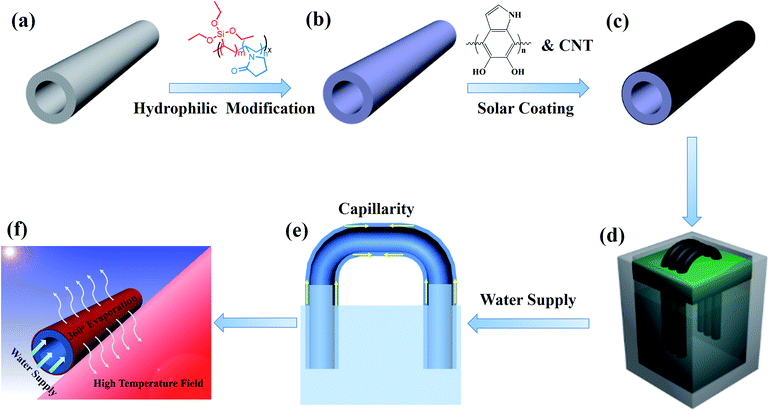
Scheme 1 illustrates the fabrication process of PTFE/CNT hollow fiber membranes for solar-to-steam conversion. To endow the PTFE hollow fiber with sufficient water self-wicking capability, the membrane was modified by an interface crosslinking strategy according to our previous report.28 First, 3.75 g NVP and 2.75 g VTES were dissolved in 100 g TEP, and then 0.08 g AIBN was added to the solution to initiate polymerization at 80 °C for 24 h to obtain a precopolymer solution, which was then diluted with an equal volume of water. Afterwards, the PTFE hollow fiber membrane was immersed in the mixed solution for 2 h, and hydrophilic modifiers PVP-VTES were transferred onto the porous membrane and further immobilized on the membrane via hydrolysis and crosslinking reactions in hot water at 60 °C for 12 h. The modified hydrophilic membrane was dried at room temperature for further modification. The pristine hydrophobic PTFE membrane and the modified hydrophilic PTFE membrane were named HFO and HFH, respectively.Dopamine hydrochloride (2 g L−1) was dissolved in a Tris buffer solution (pH = 8.5) with CuSO4/H2O2 to accelerate self-polymerization.29 Then, the hydrophilic hollow fiber membranes HFH were immediately immersed into the above solution at room temperature for 2 h to form an adhesive bio-glue layer. Afterwards, PDA-modified hollow fiber membranes were transferred to another dopamine solution including 0.5 g L−1 CNT for further 2 h to robustly load CNTs. The as-prepared PTFE/CNT composite hollow fiber was named n-HFC, where n is the number of fibers used in the evaporation experiment.
2.4 Solar-to-steam conversion experiments
The heteromorphic arch-like evaporator was facilely set up as shown in Scheme 1d and e. Thanks to the flexibility and robustness of the PTFE hollow fiber, it can be bended and arranged like an arch bridge and self-stand in the air with two ends plugging into the base support on the water surface, and more fibers can be assembled alongside to form a no-planar heteromorphic array. As the minimum unit, a single hollow fiber was able to absorb energy directly from the sun and additionally from the absorptive base support (e.g. PS foam, PVDF membrane and carbon cloth can absorb solar energy from the above sun and convert into extra heat) via thermal convection and radiation. Enough water was self-pumping up to the air/membrane surface along the hollow fiber through the hydrophilic and capillary nano-fibrous structure in cross section. The incident sunlight was absorbed by the base support, and the hollow fiber membrane was used to generate high-temperature fields (heat fields) and steam, respectively. Conversely, the produced heat was able to heat the arch-like hollow fiber in the air to inspire extra evaporation, as shown in Scheme 1f.A solar simulator (HM-Xe500W) equipped with an optical filter for the standard AM 1.5 G spectrum was used to carry out the steam generation experiments at 24 °C and ∼40% humidity. We cautiously calculate the evaporation rate (m) and apparent efficiency (η) of the heteromorphic arch-like evaporator under one sun illumination according to eqn (1) and (2), respectively:
| m = Δm/A1 | (1) |
| η = m′ × (Lv + Q)/Pin | (2) |
3. Results and discussion
3.1 Morphology of hollow fiber membrane
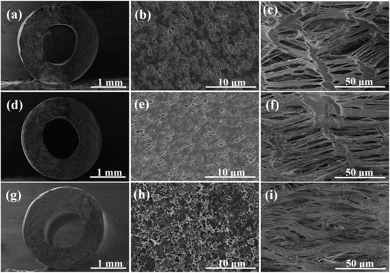
The PTFE hollow fiber was chosen as the support due to its physicochemical robustness. The robust and flexible PTFE hollow fiber allows for versatile array configuration and outdoor operation under sun irradiation. The bio-adhesion of polydopamine extended the tensile strain while maintaining the high tensile stress around 50 MPa (Fig. S1†).PTFE hollow fiber was wrapped and welded by a flat sheet PTFE membrane to minimize the surface pore size. The cross-linking immobilization of hydrophilic PVP-VTES slightly decreased the surface porosity (Fig. 1b and e). Further coating of PDA/CNT caused a rough and fluffy morphology for enhanced solar absorption in Fig. 1h. Plentiful CNTs were uniformly embedded on the PTFE membrane surface via the bio-glue adhesion of PDA in a large-scale observation (20 μm, Fig. S2†) without significantly influencing the pore size (∼0.18 μm, Fig. S3†). The modified fiber keeps a high porosity of ∼82% (Fig. S4†), which is beneficial to free flow of water and escape of steam. The inner surface exhibited a typical fibril-node micro-structure due to the uniaxial stretching process. The periodical nano-fibrils are highly oriented parallel to the stretching direction (Fig. 1c, f and i and S5†), which serve as water transport pathways from the beneath water to the membrane/air interface for interfacial evaporation. In addition, the hydrophilic modification promoted spontaneous wetting and capillary water flow along the fiber. The water holding capacity is crucial to water supply during solar-driven interfacial evaporation. The hydrophilic PTFE/CNT hollow fiber demonstrated an excellent water drawing rate (0.2 cm s−1) and enhanced water bearing capacity (∼162.7 wt%, Table S1†). It can self-lift water vertically for 6 cm in 30 s, as shown in Fig. S6.†
3.2 Wettability and light absorption
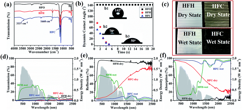
The membrane chemistry was examined by ATR-FTIR, as shown in Fig. 2a. The hydrophilic membrane HFH displayed a new peak at 1660 cm−1 compared with the pristine membrane HFO, corresponding to the stretching vibration of C![[double bond, length as m-dash]](https://www.rsc.org/images/entities/char_e001.gif) O in PVP-VTES. It was weakened in HFC by PDA/CNT coating, and the peak width became larger assigned to the N–H bond bending vibration in PDA at 1600 cm−1, resulting in an overlap of these two peaks. In addition, HFC demonstrated a characteristic peak at 3337 cm−1 attributed to the stretching vibration of N–H and –OH in PDA and CNT. All these characteristic peaks indicated the successful immobilization of solar-thermal coating PDA/CNT and hydrophilic PVP-VTES.
O in PVP-VTES. It was weakened in HFC by PDA/CNT coating, and the peak width became larger assigned to the N–H bond bending vibration in PDA at 1600 cm−1, resulting in an overlap of these two peaks. In addition, HFC demonstrated a characteristic peak at 3337 cm−1 attributed to the stretching vibration of N–H and –OH in PDA and CNT. All these characteristic peaks indicated the successful immobilization of solar-thermal coating PDA/CNT and hydrophilic PVP-VTES.
The wettability was investigated via contact angle measurement, as shown in Fig. 2b. The pristine PTFE membrane HFO showed a high and stable contact angle (142°), and the contact angle of HFC decreased instantaneously from ∼50° to 0° in 5 s due to the introduction of versatile carbonyl, carboxyl, hydroxyl and amino groups. The significantly improved wettability enhanced the water holding capacity and water self-lifting rate, as shown in Tables S1, S2 and Fig. S6.† In the operation of a solar evaporator, enough water can be spontaneously pumped up to the membrane/air interface from two lumen ends. The directional nano-fibrils in the cross-section promoted the fast water transportation via capillary force. Moreover, the enhanced hydrophilicity offers excellent anti-fouling performance to microorganisms, which is implicated to practical operation in source of wastewater and seawater. As shown in Fig. S7,† the hydrophilic membrane HFH (89.6 μg cm−2) and HFC (25.6 μg cm−2) absorbed much less BSA than pristine PTFE membrane HFO (128.1 μg cm−2). The improved anti-fouling performance is ascribed to the presence of hydration layers and the electrostatic exclusion.
The optical transmission and reflection of HFH and HFC were measured using a UV-VIS-NIR spectroscope. The wet HFC showed deep dark colors, indicating enhanced light absorption. From Fig. 2c–e, the reflection of wet HFC can be greatly suppressed from ∼20.3% to ∼5.5% (weighted by AM 1.5 G), while keeping almost zero transmission. The light absorption can achieve a high rate of ∼94.5% across a wide range of wavelengths (200–2500 nm), as shown in Fig. 2f. The PDA/CNT coating offered an intrinsic solar absorption as a competitive carbonaceous/polymeric composite ascribed to lattice vibrations. Besides, the saturated water replaced the air in open pores and generated a hydrated surface, which further reduced the diffuse reflection on the rough solid/air surface and thus promoted the highly efficient absorption of near-infrared light.33–35 The sole PDA coating without CNT produces a lower light absorption of 85% as a contrast (Fig. S8 and S9†).
3.3 Exceptional solar-driven evaporation
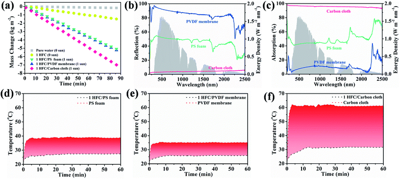
For the most commonly used planar evaporator, the projected area, evaporative area and illumination area are equal, which therefore limits the further exploitation of inexhaustible solar energy. The heteromorphic arch-like solar evaporator was constructed as depicted in Scheme 1d. The arch-like configuration maximizes the energy exploitation directly from the overhead sun and additionally from the below base, which therefore boosts the water production via a full 360° interface evaporation. The sunlight can be directly absorbed by the upward cambered surface of the hollow fiber and converted into localized surface energy via the solar-thermal coating of PDA/CNTs. In addition, the absorptive base can capture the incident sunlight, bypass the arch-like hollow fiber and generate an extra thermal energy field without increasing the solar flux. The impending arch-like self-supporting hollow fiber could utilize the extra energy from the base by means of reflection, radiation and convection for enhanced interfacial evaporation under one sun irradiation. The pensile cylindrical configuration provides 360° evaporation from sunny and shady sides of the hollow fiber. The cylindrical hollow fiber allows for maximized evaporative area, which is 3.454 times as high as the projected area. Therefore, the steam generation based on the arch-like hollow fiber could be fully promoted via exploiting extra heat from the base and a maximized full 360° evaporation without recourse to increasing solar intensity, as exhibited in Scheme 1f.As shown in Fig. 3a, the natural evaporation rate of a single hollow fiber (1.07 kg m−2 h−1) was much higher than that of pure water (0.13 kg m−2 h−1) under dark field. The solar irradiation of the 1HFC/PS foam hollow fiber further enhanced the steam production to 3.73 kg m−2 h−1 under 1 sun illumination, which is far beyond the theoretical value (the theoretical evaporation rate is 1.59 kg m−2 h−1 based on the evaporation enthalpy of 2260 kJ kg−1 at 100 °C) and outnumbers most of state-of-the-art solar-to-steam evaporators.1,2,9,11–13,26,31,36–53
As mentioned above, the heteromorphic arch-like hollow fiber acquires a record value beyond that of state-of-the-art evaporators. Both maximized interface evaporation and extra thermal source generation from the base contribute to high steam production. Therefore, the solar absorption of the base influences the solar-to-steam conversion efficiency significantly. As shown in Fig. 3a–c, 1-HFC-carbon cloth (high absorption 95%) exhibited a record rate of steam generation of 4.88 kg m−2 h−1, which is higher than that of 1-HFC-PS (3.73 kg m−2 h−1, medium absorption 48%) and 1-HFC-PVDF (3.63 kg m−2 h−1, low absorption 10%). We measured the temperature field distribution on the overhead hollow fiber and bottom base using an infrared thermal imager, as shown in Fig. 3d–f. It is found that carbon cloth gives rise to a high temperature of 61.5 °C compared to the PS foam (39.1 °C) and PVDF membrane (35.3 °C). Therefore, extra energy was gaining from the higher temperature base to heat the overhead hollow fiber (25–30 °C) via thermal radiation and convection under 1 sun input.
The direct solar energy input and the extra energy intake from the base are analyzed in Table 1. The detailed calculation based on irradiation and convection is illustrated in ESI.† Clearly, besides the solar energy absorbed by the hollow fiber (945 W), additional thermal energy was produced from the base and supplied to the overhead hollow fiber. Carbon cloth produced the highest extra thermal energy (1792 W) and resulted in a theoretical evaporative rate of 4.07 kg m−2 h−1, which is close to the experimental value (3.81 kg m−2 h−1) after subtracting the natural evaporation.
| Support | Light intensity (W) | Energy source from support (W) | Evaporation enthalpy (kJ kg−1) | Theoretical value (kg m−2 h−1) | Experimental value (kg m−2 h−1) |
|---|---|---|---|---|---|
| PS foam | 945 | 690 | 2459 | 2.47 | 2.66 |
| PVDF membrane | 945 | 526 | 2456 | 2.24 | 2.56 |
| Carbon cloth | 945 | 1792 | 2469 | 4.07 | 3.81 |
Although only one standard simulated sun was applied to the fiber, the fiber can still absorb extra energy from the base thermal source for enhanced evaporation. As a thermodynamic open system, the suspended single PTFE/CNT hollow fiber can achieve a high apparent efficiency η of 261.3%, 182.7% and 174.6% when the carbon cloth, PS foam and PVDF membrane were used as the base material, respectively, as listed in Table S3.†
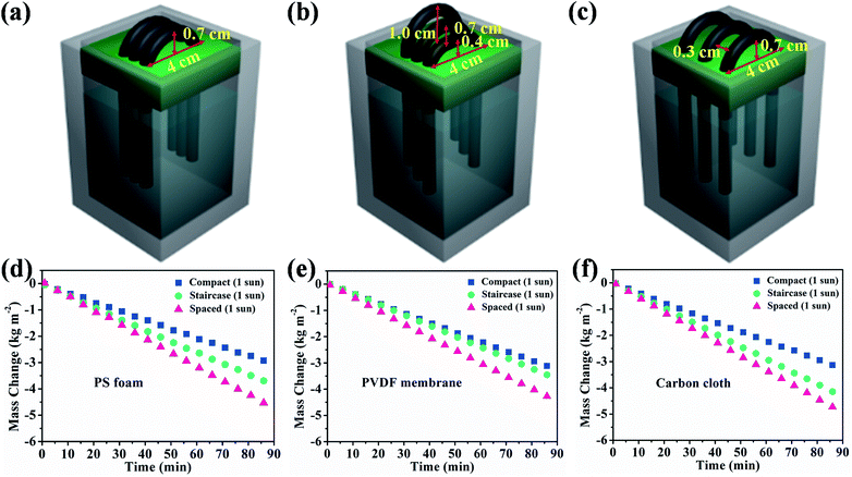
Multiple hollow fibers were aligned in a parallel and compact array. The evaporation rate was decreased and plateaued at ∼2.10 kg m−2 h−1 when the assembled fiber number increased to 3, 4 and 5, as shown in Fig. S10.† The decreased evaporation was ascribed to the light shielding by the compact array. The additional thermal supply was largely cut off from the downward base. This indicates that the fiber array pattern is crucial to the scalability and practical application. We therefore varied staircase and spaced array configuration using 3 HFCs to study the generation of extra energy fields, as shown in Fig. 4b and c, and the steam production was increased to 2.60 kg m−2 h−1 and 3.14 kg m−2 h−1 respectively, as shown in Fig. 3d. The natural evaporation was 0.70 kg m−2 h−1, 0.83 kg m−2 h−1 and 0.88 kg m−2 h−1 for three arrangement manners under dark conditions, as shown in Fig. S11.† The gap among staircase or spaced aligned fibers is conducive to sunlight incidence and steam escape, while the compact array forms a highly humid domain and restricts the moisture emission from the membrane surface due to the depressed vapor pressure difference. By subtracting the dark evaporation, a 3-hollow fiber array in compact, staircase and spaced pattern still obtains high heat evaporation rates of 1.36, 1.77 and 2.26 kg m−2 h−1 with high apparent efficiencies η of 93.1%, 120.9% and 154.7%, respectively. The over-limit solar-to-steam conversion was ascribed to the extra-energy exploitation from the absorptive support without recourse to higher solar energy input. Rationally arranging the fiber array can make sunlight pass through the gaps among them, thus promoting steam generation.
Therefore, both support absorption and array arrangement influenced the energy supply. When 3 HFCs were arranged with a compact model, the steam generation keeps almost unchanged though PS support was covered by the carbon cloth or PVDF membrane, as depicted in Fig. 4d–f. The compact hollow fibers sheltered the incident light to the downward base area and largely switched off the extra thermal supply. The sheltered area showed a lower temperature, as shown in Fig. S12.† In this case, the interface evaporation was independent of the below base. In Fig. 5, the surface temperature variation of different substrates was monitored in different array patterns. It was found that the spaced configuration facilitated light absorption and caused higher support temperature than in the case of staircase and compact arrays irrespective of the base material. The carbon cloth substrate garnered most thermal energy to heat the spaced array and resulted in the highest temperature (∼53 °C), as shown in Fig. 5. Consequently, the highest evaporation rate (3.35 kg m−2 h−1) was obtained, as shown in Fig. 4f.
The solar-to-steam conversion efficiency is expressed as apparent efficiency η, real efficiency η1, and ideal solar efficiency η2 to better understand the contribution of the solar energy and extra surrounding energy. All efficiency parameters are listed in Table S3,† considering different array configurations and base materials. The combination of the overhead fiber array and base support is apparently an open thermodynamic system, which allows for heat and mass (water and vapor) exchange. The open system is applicable to actual working conditions, especially outdoor evaporation under sun illumination, which can fully exploit the surrounding energy and produce enhanced evaporation. For example, we scaled up the membrane array with 15 HFCs, as shown in Table S3,† which yields a high evaporative rate of 2.15 kg m−2 h−1 for the staircase array using the carbon cloth as the absorptive base. The 15-staircase-carbon cloth can achieve a high apparent efficiency, η, of 105.9%, a real efficiency, η1, of 76.2% and an ideal solar efficiency, η2, of 94.5%. The versatile membrane array allows for efficient control over ease, yield and scale of solar-to-steam conversion. Through engineering the configuration of the PTFE/CNT hollow fiber array and the base adsorption, solar energy can be fully exploited to accomplish enhanced interfacial solar-to-steam conversion without increasing the solar flux.
As shown in Fig. 6a and Table S4,† the evaporation rate of a single hollow fiber based on the carbon cloth is far beyond the state-of-the-art evaporators under one sun illumination.1,2,9,11–13,26,31,36–53 In consideration of the occupied area and evaporation rate, the outdoor solar-to-steam conversion experiments were carried out in a staircase manner using the carbon cloth as the absorptive base. The 15-HFC membrane array with a staircase manner using the carbon cloth as the support produced freshwater at a rate of 10–16 kg m−2 per day during continuous evaporation for 15 days including sunny and cloudy weather (Table S5†), which is enough to satisfy the daily drinking needs of 3–4 people (Fig. 6b). The PDA/CNT micro-structure of the HFC after the long-term durability test was well preserved, as shown in Fig. S14.† For distilled water from simulated seawater (3.5 wt%), the concentration of four ions Na+, K+, Mg2+ and Ca2+ decreased from 9635.54, 911.36, 294.98 and 289.54 mg L−1 to 13.85, 0.23, 2.93 and 3.94 mg L−1, respectively, far below the WHO's requirement for the ion concentration of drinking water54 and Chinese standards for drinking water quality (GB5749-2006) (Fig. S15†). Therefore, it is practical to produce fresh water on a large scale through the heteromorphic array of robust PTFE/CNT hollow fibers.
3.4 Implication of ideal devices for solar-to-steam conversion
According to the thermal analysis in Section 3.3, the high-temperature field produced by the support (PS foam, PVDF membrane or carbon cloth) through direct sunlight incidence or scattering makes a substantial contribution to evaporation for both single fibers and membrane arrays, as shown in Fig. S16.† However, the spaced configuration sacrificed the area occupied in this case, which may weaken its competence in practice. It is significant to achieve as high as water generation under certain sun illumination and certain occupied area. More practically, the staircase configuration was applicable to outdoor evaporation without sacrificing the occupied area or increasing the sun input, where the moving sunlight can shine on the base through the staircase fibers from different angles, as shown in Fig. 7. The solar energy was fully exploited for interfacial evaporation through the optimal array. Inspired by this, other natural energies, e.g. photothermal power or wind power, can also be integrated to enhance steam generation by creating an extra energy field from the support, as shown in Fig. S17.† The arch-like hollow fiber array allows for the integration of natural energy, e.g. solar irradiation, photothermal power and wind power.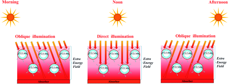 | ||
| Fig. 7 Schematic of the high-temperature field production for enhanced evaporation in a staircase manner. | ||
4. Conclusions
We have achieved exceptional interfacial solar evaporation using a heteromorphic arch-like evaporator based on PTFE/CNT hollow fibers. Carbon nanotubes (CNTs) were coated onto the membrane to enhance sunlight absorption. Water can be self-lifted up to the air/membrane surface for interfacial evaporation through the capillary nano-fibrils. Steam generation based on the arch-like hollow fiber design could be fully promoted via an extra energy source from the base and subsequent 360° evaporation. The array configuration (e.g. compact, staircase and spaced manner) influences the extra energy production from the absorptive substrate (e.g. PS foam, PVDF membrane or carbon cloth). A high evaporation rate of 2.15 kg m−2 h−1 for the 15-fiber staircase array using the carbon cloth as the base was achieved under one sun illumination. The multiple fibers array can produce freshwater at a rate of 10–16 kg m−2 per day under natural sunlight, which is enough to satisfy the daily drinking needs of 3–4 people. Moreover, the newly designed hollow fiber array can facilely integrate other natural energies to boost the interfacial evaporation and broaden its application in water purification, organic solvent claim, solute concentration, etc.Conflicts of interest
There are no conflicts to declare.Acknowledgements
Financial support is acknowledged from National Natural Science Foundation of China (51973230), Zhejiang Provincial Natural Science Foundation of China for Distinguished Young Scholars (LR20E030002), Ten thousand plan-high level talents special support plan of Zhejiang province, China (ZJWR0108020), Youth Innovation Promotion Association of Chinese Academy of Science (2014258), Ningbo Science and Technology Bureau (2014B81004, 2017C110034).Notes and references
- X. Li, W. Xu, M. Tang, L. Zhou, B. Zhu, S. Zhu and J. Zhu, Proc. Natl. Acad. Sci. U. S. A., 2016, 113, 13953–13958 CrossRef CAS.
- L. Zhang, B. Tang, J. Wu, R. Li and P. Wang, Adv. Mater., 2015, 27, 4889–4894 CrossRef CAS.
- Y. Zhang, T. Xiong, D. K. Nandakumar and S. C. Tan, Adv. Sci., 2020, 7, 1903478 CrossRef CAS.
- G. Ni, S. H. Zandavi, S. M. Javid, S. V. Boriskina, T. A. Cooper and G. Chen, Energy Environ. Sci., 2018, 11, 1510–1519 RSC.
- Z. Xie, Y. Duo, Z. Lin, T. Fan, C. Xing, L. Yu, R. Wang, M. Qiu, Y. Zhang and Y. Zhao, Adv. Sci., 2020, 7, 1902236 CrossRef CAS.
- F. Ni, N. Qiu, P. Xiao, C. Zhang, Y. Jian, Y. Liang, W. Xie, L. Yan and T. Chen, Angew. Chem., Int. Ed., 2020, 59, 19237–19246 CrossRef CAS.
- A. LaPotin, Y. Zhong, L. Zhang, L. Zhao, A. Leroy, H. Kim, S. R. Rao and E. N. Wang, Joule, 2020, 4, 1–17 CrossRef.
- X. Zhao, X.-J. Zha, L.-S. Tang, J.-H. Pu, K. Ke, R.-Y. Bao, Z.-y. Liu, M.-B. Yang and W. Yang, Nano Res., 2020, 13, 255–264 CrossRef CAS.
- F. Zhao, X. Zhou, Y. Shi, X. Qian, M. Alexander, X. Zhao, S. Mendez, R. Yang, L. Qu and G. Yu, Nat. Nanotechnol., 2018, 13, 489–495 CrossRef CAS.
- S. Tian, Z. Huang, J. Tan, X. Cui, Y. Xiao, Y. Wan, X. Li, Q. Zhao, S. Li and C.-S. Lee, ACS Energy Lett., 2020, 5, 2698–2705 CrossRef CAS.
- X. Li, J. Li, J. Lu, N. Xu, C. Chen, X. Min, B. Zhu, H. Li, L. Zhou and S. Zhu, Joule, 2018, 2, 1331–1338 CrossRef CAS.
- H. Song, Y. Liu, Z. Liu, M. H. Singer, C. Li, A. R. Cheney, D. Ji, L. Zhou, N. Zhang and X. Zeng, Adv. Sci., 2018, 5, 1800222 CrossRef.
- Y. Shi, R. Li, Y. Jin, S. Zhuo, L. Shi, J. Chang, S. Hong, K.-C. Ng and P. Wang, Joule, 2018, 2, 1171–1186 CrossRef CAS.
- L. Wu, Z. Dong, Z. Cai, T. Ganapathy, N. X. Fang, C. Li, C. Yu, Y. Zhang and Y. Song, Nat. Commun., 2020, 11, 1–12 Search PubMed.
- S. Wu, B. Gong, H. Yang, Y. Tian, C. Xu, X. Guo, G. Xiong, T. Luo, J. Yan and K. Cen, ACS Appl. Mater. Interfaces, 2020, 12, 38512–38521 CrossRef CAS.
- X. Wang, Y. He, G. Cheng, L. Shi, X. Liu and J. Zhu, Energy Convers. Manage., 2016, 130, 176–183 CrossRef CAS.
- O. Neumann, A. S. Urban, J. Day, S. Lal, P. Nordlander and N. J. Halas, ACS Nano, 2013, 7, 42–49 CrossRef CAS.
- G. Ni, N. Miljkovic, H. Ghasemi, X. Huang, S. V. Boriskina, C.-T. Lin, J. Wang, Y. Xu, M. M. Rahman and T. Zhang, Nano Energy, 2015, 17, 290–301 CrossRef CAS.
- M. S. Zielinski, J.-W. Choi, T. La Grange, M. Modestino, S. M. H. Hashemi, Y. Pu, S. Birkhold, J. A. Hubbell and D. Psaltis, Nano Lett., 2016, 16, 2159–2167 CrossRef CAS.
- K. Bae, G. Kang, S. K. Cho, W. Park, K. Kim and W. J. Padilla, Nat. Commun., 2015, 6, 1–9 Search PubMed.
- P. Tao, W. Shang, C. Song, Q. Shen, F. Zhang, Z. Luo, N. Yi, D. Zhang and T. Deng, Adv. Mater., 2015, 27, 428–463 CrossRef CAS.
- Y. Liu, S. Yu, R. Feng, A. Bernard, Y. Liu, Y. Zhang, H. Duan, W. Shang, P. Tao and C. Song, Adv. Mater., 2015, 27, 2768–2774 CrossRef CAS.
- W. Xu, X. Hu, S. Zhuang, Y. Wang, X. Li, L. Zhou, S. Zhu and J. Zhu, Adv. Energy Mater., 2018, 8, 1702884 CrossRef.
- M. Zhu, Y. Li, F. Chen, X. Zhu, J. Dai, Y. Li, Z. Yang, X. Yan, J. Song and Y. Wang, Adv. Energy Mater., 2018, 8, 1701028 CrossRef.
- M. Gao, L. Zhu, C. K. Peh and G. W. Ho, Energy Environ. Sci., 2019, 12, 841–864 RSC.
- J. Wang, Y. Li, L. Deng, N. Wei, Y. Weng, S. Dong, D. Qi, J. Qiu, X. Chen and T. Wu, Adv. Mater., 2017, 29, 1603730 CrossRef.
- H. Yang, P. Yang, X. Liu and Y. Wang, Chem. Eng. J., 2016, 299, 112–119 CrossRef CAS.
- Y. Wang, H. Lin, Z. Xiong, Z. Wu, Y. Wang, L. Xiang, A. Wu and F. Liu, J. Membr. Sci., 2016, 520, 769–778 CrossRef CAS.
- C. Zhang, Y. Ou, W. X. Lei, L. S. Wan, J. Ji and Z. K. Xu, Angew. Chem., Int. Ed., 2016, 55, 3054–3057 CrossRef CAS.
- X. Li, G. Ni, T. Cooper, N. Xu, J. Li, L. Zhou, X. Hu, B. Zhu, P. Yao and J. Zhu, Joule, 2019, 3, 1798–1803 CrossRef.
- N. Xu, X. Hu, W. Xu, X. Li, L. Zhou, S. Zhu and J. Zhu, Adv. Mater., 2017, 29, 1606762 CrossRef.
- B. Henderson-Sellers, Q. J. R. Meteorol. Soc., 1984, 110, 1186–1190 CrossRef.
- J. A. Curcio and C. C. Petty, J. Opt. Soc. Am., 1951, 41, 302–304 CrossRef CAS.
- S. A. Twomey, C. F. Bohren and J. L. Mergenthaler, Appl. Opt., 1986, 25, 431–437 CrossRef CAS.
- J. Lekner and M. C. Dorf, Appl. Opt., 1988, 27, 1278–1280 CrossRef CAS.
- Y. Ito, Y. Tanabe, J. Han, T. Fujita, K. Tanigaki and M. Chen, Adv. Mater., 2015, 27, 4302–4307 CrossRef CAS.
- M. Ye, J. Jia, Z. Wu, C. Qian, R. Chen, P. G. O'Brien, W. Sun, Y. Dong and G. A. Ozin, Adv. Energy Mater., 2017, 7, 1601811 CrossRef.
- P. Zhang, J. Li, L. Lv, Y. Zhao and L. Qu, ACS Nano, 2017, 11, 5087–5093 CrossRef CAS.
- H. Ren, M. Tang, B. Guan, K. Wang, J. Yang, F. Wang, M. Wang, J. Shan, Z. Chen and D. Wei, Adv. Mater., 2017, 29, 1702590 CrossRef.
- Z. Wang, Q. Ye, X. Liang, J. Xu, C. Chang, C. Song, W. Shang, J. Wu, P. Tao and T. Deng, J. Mater. Chem. A, 2017, 5, 16359–16368 RSC.
- H. Liu, X. Zhang, Z. Hong, Z. Pu, Q. Yao, J. Shi, G. Yang, B. Mi, B. Yang and X. Liu, Nano Energy, 2017, 42, 115–121 CrossRef CAS.
- Q. Chen, Z. Pei, Y. Xu, Z. Li, Y. Yang, Y. Wei and Y. Ji, Chem. Sci., 2018, 9, 623–628 RSC.
- Y. Yang, R. Zhao, T. Zhang, K. Zhao, P. Xiao, Y. Ma, P. M. Ajayan, G. Shi and Y. Chen, ACS Nano, 2018, 12, 829–835 CrossRef CAS.
- L. Zhu, M. Gao, C. K. N. Peh, X. Wang and G. W. Ho, Adv. Energy Mater., 2018, 8, 1702149 CrossRef.
- X. Yang, Y. Yang, L. Fu, M. Zou, Z. Li, A. Cao and Q. Yuan, Adv. Funct. Mater., 2018, 28, 1704505 CrossRef.
- T. Li, H. Liu, X. Zhao, G. Chen, J. Dai, G. Pastel, C. Jia, C. Chen, E. Hitz, D. Siddhartha, R. Yang and L. Hu, Adv. Funct. Mater., 2018, 28, 1707134 CrossRef.
- L. Sun, Z. Li, R. Su, Y. Wang, Z. Li, B. Du, Y. Sun, P. Guan, F. Besenbacher and M. Yu, Angew. Chem., Int. Ed., 2018, 130, 10826–10831 CrossRef.
- Y. Wang, C. Wang, X. Song, S. K. Megarajan and H. Jiang, J. Mater. Chem. A, 2018, 6, 963–971 RSC.
- P. Zhang, Q. Liao, T. Zhang, H. Cheng, Y. Huang, C. Yang, C. Li, L. Jiang and L. Qu, Nano Energy, 2018, 46, 415–422 CrossRef CAS.
- J. Chen, J. Feng, Z. Li, P. Xu, X. Wang, W. Yin, M. Wang, X. Ge and Y. Yin, Nano Lett., 2018, 19, 400–407 CrossRef CAS.
- X. Hu, W. Xu, L. Zhou, Y. Tan, Y. Wang, S. Zhu and J. Zhu, Adv. Mater., 2017, 29, 1604031 CrossRef.
- Y. Li, T. Gao, Z. Yang, C. Chen, W. Luo, J. Song, E. Hitz, C. Jia, Y. Zhou and B. Liu, Adv. Mater., 2017, 29, 1700981 CrossRef.
- C. Xing, D. Huang, S. Chen, Q. Huang, C. Zhou, Z. Peng, J. Li, X. Zhu, Y. Liu and Z. Liu, Adv. Sci., 2019, 6, 1900531 CrossRef CAS.
- A. H. Smith, M. Bates, C. M. Steinmaus and O. von Ehrenstein, Arsenic epidemiology and drinking water standards, 2003 Search PubMed.
Footnote |
| † Electronic supplementary information (ESI) available. See DOI: 10.1039/d0ta09368h |
| This journal is © The Royal Society of Chemistry 2021 |

