DOI:
10.1039/D0SM02014A
(Paper)
Soft Matter, 2021,
17, 4578-4593
Characterizing viscoelastic properties of synthetic and natural fibers and their coatings with a torsional pendulum
Received
13th November 2020
, Accepted 8th March 2021
First published on 18th March 2021
Abstract
Characterizing and understanding the viscoelastic mechanical properties of natural and synthetic fibers is of great importance in many biological and industrial applications. Microscopic techniques such as micro/nano indentation have been successfully employed in such efforts, yet these tests are often challenging to perform on fibers and come with certain limitations in the interpretation of the obtained results within the context of the macroscopic viscoelasticity in the fiber. Here we instead explore the properties of a series of natural and synthetic fibers, using a freely-oscillating torsional pendulum. The torsional oscillation of the damped mass-fiber system is precisely recorded with a simple HD video-camera and an image processing algorithm is used to analyze the resulting videos. Analysis of the processed images show a viscoelastic damped oscillatory response and a simple mechanical model describes the amplitude decay of the oscillation data very well. The natural frequency of the oscillation and the corresponding damping ratio can be extracted using a logarithmic decrement method and directly connected to the bulk viscoelastic properties of the fiber. We further study the sensitivity of these measurements to changes in the chemo-mechanical properties of the outer coating layers on one of the synthetic fibers. To quantify the accuracy of our measurements with the torsional pendulum, a complementary series of tests are also performed on a strain-controlled rheometer in both torsional and tensile deformation modes.
1 Introduction
Thin flexible viscoelastic fibers play an essential role in many different applications. Examples are abound in the textile and cosmetics industries alongside natural and biological applications such as human hair, spider silk and mussel threads to list a few examples where the mechanical properties of soft fibers are of significant importance.1–10 In many natural or synthetic fibers, such as human hair, a thin outer shell, also known as the cuticle, is placed around the core of the fiber or cortex.11 Many cosmetic products or techniques that are used in processes such as permanent waving, affect the overall behavior of human hair by modifying the viscoelastic properties of the outer cuticle layers.3 Similarly, in many applications in the textile industry fibers are coated with a variety of protective polymer coatings.12 In many of these fiber coating processes there is a need to quantify the effect of cuticle treatments or coating properties on the overall mechanical behavior of the fiber. Many recent studies on fibers such as human hair have focused on probing the properties of the external cuticle layers with advanced techniques such as AFM (atomic force microscopy).13 These methods can report very accurate local microscopic measurements, but are costly in their implementation and required expertise and are inherently limited in providing macroscopic information on the bulk viscoelastic properties of the whole fiber.
In order to accurately measure macroscopic mechanical properties of fibers several different methods have been developed over the years. For example, when characterizing the properties of human hair, different tests based on tension, bending and torsion of a fiber have been pursued in the cosmetics industry.3 However, as noted by Bogaty14 and Wolfram and Lindemann,11 results from tension and bending tests of human hair are more sensitive to the mechanical properties of the inner cortex of the fiber, while torsion-based tests are more sensitive to the properties of the outer cuticle layers. This may be due in part to differences in material structure caused by the orientation of cells within the cuticle and cortex of human hair respectively as proposed by Wolfram and Lindemann.11 However, as a result of the underlying geometry and kinematics of deformation which we will discuss in detail later, torsional measurements are inherently more sensitive to the mechanical properties of the outer layers of a cylindrical fiber. Thus, in the present study we focus on torsional measurements for fiber characterization and revisit an established method known as a torsional pendulum test.15 We show that data from this simple test are directly connected to bulk viscoelastic properties of the fiber. Furthermore, by characterizing the systematic change in torsional properties of a set of coated fibers, we show that this method is indeed uniquely sensitive to mechanical changes in the outermost surface layers of fiber. Finally, using an appropriate theoretical framework, we demonstrate how to quantify the effects of viscoelastic coatings on the macroscopic mechanical behavior of the fiber.
1.1 Historical background
Torsion balances and pendulums have been used extensively for precise measurements in an astonishingly diverse list of scientific studies. Nearly one hundred different versions of the torsional pendulum, all having the common feature of a test mass suspended from a slender fiber, have been reported in literature.16 In terms of historical background, it is possible that the very first torsion balance was used as a compass or “sailing needle” in ancient China. Torsion balances were later used by Charles Augustin de Coulomb, and independently by John Michell, for detecting and measuring small forces.16,17 Later, Cavendish18 used a similar setup to determine “the mean density of the earth” which is now interpreted as a value for the gravitational constant G. Faraday and Pierre Curie also benefited from the precision of a torsional balance in their research on diamagnetism and discovery of the Curie temperature.19,20 The origin of success of this time-tested measurement system rests on a simple principle. In many other force measurement devices, weak signals compete with the background gravitational field. In a torsional pendulum however, the gravitational force of the earth on the test body is orthogonal to the plane in which the forcing signal of interest occurs, thereby isolating the signal from gravitational perturbations and allowing even weak forces to be measured systematically. Even in current state-of-art measurements of minute forces, this elegant principle has ensured that torsional balances and pendulums remain relevant as a precise measurement tool.21
The torsional balance has also played a crucial role in determining the mechanical properties of soft viscoelastic materials.22 Boltzmann analyzed the damped torsional oscillations of thin piano wires and glass and silk fibers performed by Streintz, Kohlrausch and Weber respectively.23–27 Early designs of the “McMichael viscometer”,28,29 used torsion balances to accurately measure the torque response of materials under shear deformations. Many other researchers have used torsional balances in a similar manner or used the torsional pendulum setup to directly characterize mechanical properties of different filaments and fibers.1,30–35 More broadly, soft matter scientists are still using torsion balances and pendulums today in their studies of different viscoelastic materials.36,37
Many of the mentioned studies have focused on monofilament fibers. However, Gillham and coworkers38–41 used torsional braid analysis (TBA) in several studies to record the temporal evolution of the viscoelastic properties in thermosetting polymers during the curing process. In these studies, a fine fabric braid is saturated with the test polymer liquid formulation. As the solution cured, the researchers performed torsional pendulum measurements to record the enhancement in the mechanical properties of the braid, from which they qualitatively measured the mechanical properties of the curing polymer. This technique has been used in more recent studies by Kiran and Hassler42 to assess the thermal transition in moduli of polymers when exposed to supercritical or compressed fluids. Because of the unknown nature of the interaction between fibers and cured polymer in the braid assembly, these tests provide qualitative measurements of the relative rigidity (a measure of the change in the storage modulus) and the relative damping (a measure of the change in the loss modulus) of the curing systems.42
1.2 Principle of operation for a torsional pendulum test
A torsional pendulum consists of a disc or weight that is attached to a vertically suspended slender test fiber in an axisymmetric configuration. In a typical experiment, the disc is gently twisted to an out-of-equilibrium position by the operator and then released. The disc consequently goes through damped torsional oscillations around its equilibrium position and oscillates at a fixed resonant frequency. The oscillatory nature of this motion is a direct indication of the torsional deformation that the fiber experiences. The oscillatory response of the system arises from the dynamical interchange between the kinetic energy of the oscillating disc and the stored elastic energy in the twisted fiber. For an ideal elastic fiber in a vacuum, in the absence of any source of energy dissipation, the torsional pendulum should oscillate permanently with a constant value of overall mechanical energy determined by the initial angular rotation imposed. A vibrating mass-spring system is an appropriate mechanical analogue for this hypothetical dissipation-free condition.43 Similar to the mass-spring analogue, the natural resonant frequency of the torsional pendulum increases with the fiber elasticity and decreases with the moment of inertia of the disc. Thus, keeping all other parameters constant, a higher natural resonant frequency indicates a higher elastic modulus of the fiber.
For fibers made of real non-idealized materials, the overall system energy is constantly dissipated during the torsional oscillations due to different sources of damping such as the viscoelastic properties of the fiber and air friction acting on the disc. For small discs oscillating in low viscosity media such as air, the main source of energy dissipation stems from the viscoelastic damping behavior of the materials from which the fiber is constructed, and this is manifested as a gradual decrease in the amplitude of oscillations until the pendulum finally comes to rest at its original angular position. A faster or slower decay indicates a respectively higher or lower rate of viscous dissipation and, in the language of linear viscoelasticity, this decay rate of the oscillation amplitude is correlated with the effective loss modulus of the material that comprises the fiber.
Measurement of the natural resonant frequency and oscillation decay rate can readily be performed through time domain measurements (the resonant frequency and the decay rate are, respectively, the inverse of the oscillation period and the decay timescale). Consequently, the effective bulk viscoleastic properties of the fiber can be measured through quantification of the different timescales involved in the time-periodic phenomenon, an aspect which has a certain practical benefit for our measurements. Time is a quantity that can be measured with a considerably higher degree of accuracy, compared to other measurable quantities such as length or weight, a fact which has also been a crucial element in solving well-known challenges such as the longitude problem in naval navigation.44 Thus, in the field of instrumentation and sensor design, it is well known that one of the most accurate methods for measuring many material quantities is by capturing the timescale of a relevant dynamic system.45 The torsional pendulum setup also benefits from this principle.
2 Experimental setup
2.1 Torsional pendulum
The different elements of our experimental setup are shown in Fig. 1. The torsional pendulum setup consists of two laser-cut acrylic discs connected to each other via the test fiber (Fig. 1(a and b)). The top disk is fixed and the bottom disc is suspended vertically from the fiber and free to oscillate. In our configuration both discs are transparent and the bottom disc has a radius of 1 cm and a thickness of 3 mm.† The test fiber connects the two discs together and is carefully held in position by gluing it into two hollow syringe needles that are fixed at the centerpoint and aligned orthogonal to the plane of each disc. The top disc is fixed onto a transparent stand attached to an adjustable stage, shown in Fig. 1(c). The stage and the torsional pendulum are placed into a home-made transparent humidity chamber that is also made of acrylic. As indicated in Fig. 1(d), a uniform LED light source illuminates the pendulum from the top. A mirror is placed at a 45 degree angle below the chamber to facilitate a horizontal view of the bottom of the free oscillating disc. To control the humidity of the chamber, saturated salt solutions of different compositions and concentrations are prepared and placed into the chamber alongside a humidity sensor to accurately measure the local values of relative humidity. Using a suitable volume of the saturated salt solution (∼100 ml), the chamber reaches a constant value of relative humidity in about 10–20 minutes. The simplicity of the current design allows the user to make several chambers and place different salts into each of them which ensures that tests can be performed at different values of local humidity as well as cyclic tests with user-specified humidity variations. Furthermore, unlike conventional rheometers or other mechanical test instrumentation, the compact size of the torsional pendulum setup permits easy installation inside controlled temperature and humidity chambers. To optically image the torsional oscillations of the free bottom disc, we place two black dots on the disc using a pen. As shown in Fig. 2(a), one dot is placed at the center (r = 0) and another at an off-center position (0 < r < Rdisc). Using the LED illumination from above, the relative position of the shadows created by the two dots can be observed through the 45 degree mirror placed below the disc. As the disc oscillates, movies of the angular displacement of the two dots are recorded at 30 frames per second (FPS) using a Canon camera equipped with a Canon EF 100 mm f/2.8 macro lens. We should emphasize that similarly high-quality recordings can also be obtained with the digital camera of a commercial cellphone and its built-in optics.
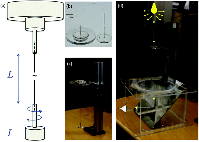 |
| | Fig. 1 Different elements of the experimental setup: (a and b) the torsional pendulum consists of a laser-cut acrylic base disc fixed at the top and a free disc at the bottom. Each end of the test fiber of interest is glued into hollow syringe needles prefixed at the center-line of each disc. (c) The stationary top disc is fixed on a transparent stand on a height adjustable stage. (d) The stage and the torsional pendulum are placed into a lab-made transparent humidity chamber made of acrylic. A uniform LED light source illuminates the pendulum from the top. A 45° degree angled mirror is placed below the chamber to facilitate a clear bottom view of the free disc by an external observer or camera. | |
 |
| | Fig. 2 Details of the image analysis: (a) each frame of the recorded movie is extracted as a raw image. (b) Two black dots are placed on the free bottom disc (one at the center r = 0 of the disc and a second dot in an off-center position 0 < r < Rdisc). The spatial coordinates of these two dots determine the angular position of the off-center dot at any given time. (c) Using ImageJ each frame of the movie is converted into a binary image in which the two dots are seen as the two largest white circles. The smaller dots are noise that can be filtered out based on their size. (d) A cleaned image frame shows only the position of the two dots. Repeating this process for each frame, we record the spatial coordinates of the two dots in each frame and determine the torsional angle θ(t). | |
The recorded movie provides the raw data for a typical test. To quantify the angular rotation of the oscillating disc, we rely on the recorded positions of the two dots. In an idealized torsional oscillation, the disc only rotates around the center-line (which is also the fiber axis) and consequently the center dot should remain fixed in space as the other off-center dot rotates around it. However, because of small imperfections resulting from the manual release of the disc, it is almost inevitable that the pendulum will also have some small translational vibration added to its rotational motion. However, since the two dots on the rigid disc experience identical translational displacements, we can remove their in-phase translational motion by subtracting their spatial coordinates and thereby determine the angular rotation of the disc. In other words, following the position of the off-center dot relative to the center dot enables us to cancel out systematic noise induced by residual translational motion and isolate the key signal of interest; i.e. angular displacements of the fiber/disc system. This known benefit of the differential measurement principle is widely used in the design of sensors.46
2.2 Image analysis
To quantify the angular position of the disc over time, we used ImageJ (a Java-based image processing program that is distributed in the public domain) to perform a simple analysis procedure. As shown in Fig. 2, each frame of the recorded movie is processed as a raw image in which the frame number represents the time label for that specific configuration. Each image is converted to gray scale and after adjusting the image contrast threshold we can apply an edge-finding algorithm to remove most of the noise and identify the boundaries of the two dots on the disc. Repeating these steps for all images results in a binary image stack. Fig. 2(c) shows a binary version of a single image with the two dots shown as large filled white circles and smaller bright dots from optical noise, which we filter out by applying a size threshold. The final outcome, as shown in Fig. 2(d), is an empty frame with the two dots as the only detectable objects. Next, the following procedure is automatically repeated for every frame: (1) the spatial coordinates of the two dots (denoted [x1, y1] and [x0, y0] for the off-center and center dots respectively) are measured; (2) the position of the off-center dot relative to the disc center (rp = (x1 − x0)ex + (y1 − y0)ey) is recorded; and (3) using simple trigonometric relationships, the angular position of the oscillating disc at each instant of time θ(t) = arctan[(y1 − y0)/(x1 − x0)] is extracted.
3 Results and analysis of the data
In a typical test, the measured angular position of the disc θ(t) oscillates around its initial equilibrium value ![[small theta, Greek, macron]](https://www.rsc.org/images/entities/i_char_e0c9.gif) . One can define the difference between these two angles as a new variable ϑ(t) ≡ θ(t) − . Fig. 3(a) shows the temporal evolution of ϑ(t) in a torsional pendulum test performed on a single human hair fiber. The oscillatory nature of the phenomenon is readily apparent and the periodic spacing between the peaks indicates a harmonic motion with a fixed natural resonant frequency ωn. The decay in the amplitude of the measured angular position is a direct indicator of viscous losses within the fiber. In fact a semi-logarithmic plot of the data in Fig. 3(b) shows that the amplitude decays in a well-defined exponential manner from which a characteristic decay rate can easily be extracted. Moreover, the apparent constant slope of a hypothetical line connecting the oscillation peaks in Fig. 3(b) demonstrates that, similar to natural resonance, the decay rate τvis−1 also remains constant during the experiment which results in a constant value of the logarithmic decrement Λ which is defined as the natural log of the ratio of the amplitudes of any two successive peaks log(ϑi+1max/ϑimax).
. One can define the difference between these two angles as a new variable ϑ(t) ≡ θ(t) − . Fig. 3(a) shows the temporal evolution of ϑ(t) in a torsional pendulum test performed on a single human hair fiber. The oscillatory nature of the phenomenon is readily apparent and the periodic spacing between the peaks indicates a harmonic motion with a fixed natural resonant frequency ωn. The decay in the amplitude of the measured angular position is a direct indicator of viscous losses within the fiber. In fact a semi-logarithmic plot of the data in Fig. 3(b) shows that the amplitude decays in a well-defined exponential manner from which a characteristic decay rate can easily be extracted. Moreover, the apparent constant slope of a hypothetical line connecting the oscillation peaks in Fig. 3(b) demonstrates that, similar to natural resonance, the decay rate τvis−1 also remains constant during the experiment which results in a constant value of the logarithmic decrement Λ which is defined as the natural log of the ratio of the amplitudes of any two successive peaks log(ϑi+1max/ϑimax).
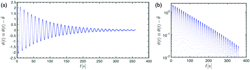 |
| | Fig. 3 Output data from a recorded oscillation test: the angular position of the free disc ϑ(t) ≡ θ(t) − versus time in (a) linear–linear and (b) log-linear plots. | |
3.1 Damped harmonic oscillator
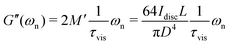
The qualitative similarity between the results of a torsional pendulum test and a damped harmonic oscillator can be expanded into a quantitative comparison through a simple mechanical analogue. As shown in the inset image of Fig. 4, a typical damped harmonic oscillator consists of a mass-spring-dashpot assembly that gives rise to oscillations at a resonant frequency (through mass and spring interaction) and also a viscous dissipation mechanism (through the viscous dashpot). Replacing the usual displacement parameter in this mechanical analogue (with units of length) to strain or torsional deformation angles (both dimensionless) transforms the spring constant to a modulus G [Pa], the dashpot coefficient to a viscosity η [Pa s] and the mass to an apparent or effective mass M′ [kg m−1]. When the system is not over-damped, the solution for the free vibration for this mechanical toy model is known to be an exponentially decaying harmonic motion which is mathematically described as:| | ϑ(t) = ϑ0![[thin space (1/6-em)]](https://www.rsc.org/images/entities/char_2009.gif) exp(−t/τvis)sin(ωnt + ϕ0) exp(−t/τvis)sin(ωnt + ϕ0) | (1) |
where ϑ(t), ωn = [(G/M′) − (η2/4M′2)]1/2 and 1/τvis = η/2M′ are respectively the oscillation angle, natural resonant frequency of the system and the viscous decay rate. The position and initial phase angle are represented by ϑ0 and ϕ0 respectively. As shown in Fig. 3 and 4, the torsional oscillation of most fibers show an under-damped behavior which indicates that the damping ratio is usually less than unity,  and consequently the natural resonant frequency can be directly approximated as
  . Proceeding with this simplifying approximation, we can also find an approximate expression for the logarithmic decrement Λ ≡ ln[ϑ(t + 2π/ωn)/ϑ(t)] = 2π/(ωnτvis) ≃ 2πξ.
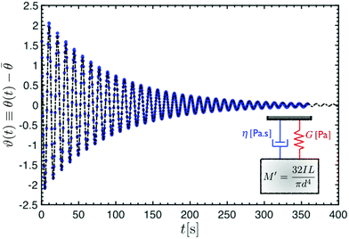 |
| | Fig. 4 Blue dots show the angular position of the free disc versus time in a torsional pendulum test performed on a human hair fiber (straight Caucasian type with a diameter of 66 μm). The dashed black line represents a theoretical fit of the damped harmonic solution (eqn (1)) to the data ϑ0 = 2.23, 1/τvis = 0.011 s−1, ωn = 0.559 s−1, ϕ0 = 2.152. Two important oscillation parameters ωn and 1/τvis are the two fitting parameters that set the oscillation frequency and damping rate respectively. The analogous mechanical model to this damped harmonic oscillator is shown in the inset drawing. | |
Blue dots in Fig. 4 show the measured angular positions from a torsional pendulum test performed on a single human hair (straight Caucasian type with a diameter of 66 μm). A fit of the proposed solution (eqn (1)) to the data is shown by a dashed line. The fit is the under-damped solution and clearly captures the entire dynamics of the oscillatory motion. While the initial angular position and phase angle (ϑ0, ϕ0) are set by the initial conditions of the test and can vary for a single fiber from one test to another, the values of natural resonant frequency and viscous decay rate (ωn, 1/τvis) represent the intrinsic aspects of the resonance phenomenon and remain unchanged for a specific test fiber. Furthermore, as the simple mechanical model of a mass-spring-dashpot system suggests, the numerical values of these two fitting constants (ωn, 1/τvis) are connected to the intrinsic elasticity G and viscous dissipation η in the model.
The fact that the dynamics of a torsional pendulum formed with a natural fiber such as human hair can be modeled by a simple damped harmonic oscillator indicates that a direct one-to-one connection can be made between the real system and the corresponding mechanical model. The inertia of the oscillating disc is captured through the apparent mass M′ and the viscoelastic properties of the test fiber set the values of the spring and dashpot parameters G and η in the model.
It is noteworthy to mention that one can also use an alternative approach based on the Laplace transform of the measured data. Similar ideas have been investigated in the analysis of creep-ringing phenomena.47 Important model variables, natural resonant frequency and viscous decay rate, are directly related to the locus of the corresponding poles in Laplace space. However, Laplace transform of measured discrete data can also lead to numerical errors.48,49 Consequently, in this study we relied on the theoretical solution for the damped harmonic oscillator in the time domain to directly fit experimentally measured datapoints and obtain values of model variables.
To quantitatively measure the viscoelastic properties of the fiber through the torsional pendulum tests, we need to establish a direct relationship between the model variables and the physical and geometrical parameters of the test.
3.2 Measuring the viscoelastic moduli
To connect the measured parameters in a torsional pendulum test of a fiber to its underlying viscoelastic properties, we need a rational framework that addresses the nature of the constitutive relationships for the material within the fiber. We assume that the fiber is made of a homogeneous material and the deformations within the material are small enough to remain in the linear domain.‡ We provide solutions for the torsion of a homogeneous cylindrical fiber assuming different constitutive relationships for the material within the fiber. This enables us to connect the measured parameters (ωn, 1/τvis) to viscoelastic properties such as the frequency-dependent elastic modulus G′(ωn), and loss modulus G′′(ωn). By assuming a circular cross-section, we benefit from existing analytical solutions for the torsion of circular fibers.50,51 This is a fairly accurate assumption for the monofilament fibers that were used in this study. It is also known that the cross-sections of thin human hair fibers, similar to the samples studied in the paper, are approximately circular.52 However, many industrial and natural fibers such as rectangular optical fibers and thicker human hair threads have non-circular cross-sections.52 For these non-circular cases, one can use an analysis similar to the one presented in this paper but with extra attention to both geometrical factors and out-of-plane warping of the non-circular cross-section.50,51,53 Corresponding correction factors for different cross-section geometries (e.g. square,51 rectangle54 and ellipse53) and details of the modified analysis are reported in the literature.50,51,53,54
3.2.1 Elastic solids.
In purely torsional deformations of a cylindrical fiber the net torque ![[scr T, script letter T]](https://www.rsc.org/images/entities/char_e533.gif) , calculated about the axis of the fiber, is constant along its axis and has the same value in each circular cross-section of the fiber. Assuming isotropic material properties and using symmetry arguments one can show that each circular cross-section rotates as a rigid material plane about the axis of the cylinder, denoted by z in polar coordinate system. In each cross-section the deformations and consequently shear strains vary linearly with radial position γzθ = r∂φ/∂z where ∂φ/∂z, the angle of twist per unit length, is constant along the fiber.§ The twist angle varies linearly from φz=0 = 0 at the fixed end to a constant value φz=L = ϑ(t) at the free end of the fiber. For linear deformations, the resulting internal shear stress also varies linearly with the radial position in each cross-section σzθ = Gr∂φ/∂z; where G is the shear elastic modulus of the material. The net torque is generated from the internal shear stress distribution in each cross-section
, calculated about the axis of the fiber, is constant along its axis and has the same value in each circular cross-section of the fiber. Assuming isotropic material properties and using symmetry arguments one can show that each circular cross-section rotates as a rigid material plane about the axis of the cylinder, denoted by z in polar coordinate system. In each cross-section the deformations and consequently shear strains vary linearly with radial position γzθ = r∂φ/∂z where ∂φ/∂z, the angle of twist per unit length, is constant along the fiber.§ The twist angle varies linearly from φz=0 = 0 at the fixed end to a constant value φz=L = ϑ(t) at the free end of the fiber. For linear deformations, the resulting internal shear stress also varies linearly with the radial position in each cross-section σzθ = Gr∂φ/∂z; where G is the shear elastic modulus of the material. The net torque is generated from the internal shear stress distribution in each cross-section  . In a cylindrical geometry with a uniform constant cross-section diameter D = 2R, the internal torque in each cross section = G(πD4/32)ϑ/L is linearly proportional to both the twist angle ϑ (which is the measured quantity in a torsional test) and the modulus of the material G (which is the parameter we seek to measure). This enables us to reorganize the equation of motion and write it in the form of conservation of angular momentum for the disc:
| |  | (2) |
where M′ = 32IL/(πD4). Since Rfiber/Rdisc ≤ 1/100, the moment of inertia of the fiber is negligible compared to the disc and I is approximated by the corresponding value for the disc alone I ≃ Idisc. Comparing this equation of motion (eqn (2)) with our mechanical vibration model (inset drawing in Fig. 4), we conclude that for a fiber made of a purely elastic solid  and 1/τvis = 0. Thus, by recording the oscillatory response of a torsional pendulum and finding the natural resonant frequency ωn through fitting consecutive peaks (as shown in Fig. 4), we can directly connect the measured natural resonant frequency to the shear elastic modulus of the material:
| |  | (3) |
All the geometrical factors such as length L and diameter D of the fiber along with the moment of inertia for the disc I ≃ Idisc are known parameters which provide the value of the lumped parameter M′ = 32IL/(πD4) as a pre-factor that connects the frequency measurements to the shear modulus of the material. As discussed before, the assumption of a purely elastic constitutive relationship for the material is an ideal case for which there is no dissipation in the mechanical energy and consequently yields a zero value for the viscous decay rate 1/τvis = 0. Real materials, however, show viscous dissipation and we now provide a solution of the torsion problem for viscoelastic solids assuming a simple Kelvin–Voigt constitutive relationship which includes both elastic and viscous effects.
3.2.2 Viscoelastic Kelvin–Voigt solid.
The Kelvin–Voigt constitutive model, which is widely used for describing the material response of viscoelastic solids, is a two-element model consisting of a spring (with constant modulus G) and a dashpot (with constant viscosity η) in parallel to each other. Since the two elements are arranged in parallel they experience identical strains but the overall stress is divided between them. The resulting dynamic mechanical response predicted by the model in small amplitude oscillatory deformations is a constant elastic modulus G′(ω) = G and a linearly increasing loss modulus G′′(ω) = ηω. During torsional deformations of a viscoelastic fiber made of a Kelvin–Voigt solid, similar to the elastic case studied above, both shear strain and strain-rate vary linearly with the radial position in each cross section γzθ = r∂φ/∂z and ![[small gamma, Greek, dot above]](https://www.rsc.org/images/entities/i_char_e0a2.gif) zθ = r∂
zθ = r∂![[small phi (variant), Greek, dot above]](https://www.rsc.org/images/entities/i_char_e0a4.gif) /∂z respectively where
/∂z respectively where  . Similarly, the twist angle per unit length and its time derivative are constant along the axis of the cylindrical fiber, ∂φ/∂z = ϑ(t)/L and
  . The resulting shear stress distribution and net torque in each cross-section are respectively
  and
and  ; in each case the overall value is the sum of an elastic and a viscous contribution. Reorganizing terms, we can write the overall equation of motion for the disc:
| | 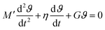 | (4) |
where, similar to the elastic case, M′ = 32IdiscL/(πD4). We now connect back to the mass-spring-dashpot analogy and conclude that for a Kelvin–Voigt viscoelastic solid, if the damping ratio is smaller than unity, 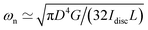 and 1/τvis = πD4η/(64IdiscL). In a freely oscillating torsional pendulum test, these expressions enable us to use the measured values of natural resonant frequency ωn and viscous decay rate 1/τvis and calculate the viscoelastic response of the material based on Kelvin–Voigt model parameters G and η:
| |  | (5a) |
| | 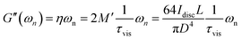 | (5b) |
Thus, for a viscoelastic fiber that follows the Kelvin–Voigt model the two material parameters, characterizing the storage and dissipation of energy (G and η respectively), set the entire linear viscoelastic behavior of the material and their corresponding values at frequency ωn are directly found by measuring the natural resonant frequency and viscous decay rate in a single torsional oscillation test. Since we assume that the Kelvin–Voigt model is valid, we can predict values of G′ and G′′ at all frequencies using the constitutive relationship which shows that G′(ω) = G ∀ ω and G′′(ω) = ηω = G′′(ωn)·(ω/ωn) ∀ ω. In other words, by using eqn (5a) and (5b), we determine the viscoelastic moduli of the fiber not only at the local natural resonant frequency where G′(ωn) = M′ωn2 and G′′(ωn) = 2M′ωn(1/τvis), but also at any arbitrary frequency ω. This is a direct result of the underlying assumption that the viscoelastic material in the fiber is characterized through a Kelvin–Voigt constitutive model.
It is important to emphasize that not all fibers will be described by the Kelvin–Voigt model and we seek to develop a rheometric protocol that does not make any a priori constitutive assumptions about the nature of the viscoelastic behavior of the material that the fiber is composed of. Thus, it is essential to develop a rational framework for analyzing the experimental results obtained from a given fiber that is composed of a general viscoelastic solid with no a priori assumption regarding the underlying constitutive equation.
3.2.3 General viscoelastic solid.
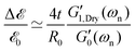
To calculate the corresponding viscoelastic properties for a fiber made of a general viscoelastic solid, we need to derive an equation of motion in the torsional oscillations of the disc which is similar to eqn (4). Many early measurements of viscoelastic properties of different solid-like materials were based on free-oscillation techniques similar to the torsional pendulum test.15,30,31,33,34,57 Results from these studies often showed a dominant resonant behavior in free vibration with a characteristic under-damped oscillatory response. The dominance of a single natural resonant frequency ωn in the response of these solid-like materials suggested that the behavior of the material during a free vibration test can be characterized by its local values of the elastic and loss moduli at the resonant frequency (i.e. G′(ωn) and G′′(ωn)). This leads to the following lumped parameter approximation for the equation of motion of an oscillating mass:15,57–59| | 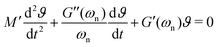 | (6) |
where M′ is again the apparent mass in the dynamics of the free-vibration (which is 32IdiscL/(πD4) for the torsional pendulum test). The dynamics of the motion, in the frequency domain, are localized around the natural resonant frequency, consequently the local viscoelastic moduli (G′(ωn) and G′′(ωn)) approximate the elastic and viscous contribution of the material. However, we emphasize that, as noted by other studies,58–61eqn (6) is not exact and can not be used without further justification for a general viscoelastic solid. In writing eqn (6) we assume that the dynamic moduli define the constitutive relationship between stress and strain; which is only strictly true for purely sinusoidal deformations and stresses.59 The bounding exponential decay envelope clearly apparent in Fig. 2 and 4 indicate the presence of additional timescales in the system response. This issue was a significant difficulty in performing early measurements of viscoelastic properties59,62 and it seemed as if “experiments using damped vibrations cannot give direct information about dynamical mechanical properties which are only defined for undamped sinusoidal oscillations”.61 However, Struik61 noted that despite the “approximate” nature of eqn (6) the value of the measured moduli for many solid viscoelastic materials in free-vibration tests using this approximation were surprisingly accurate. Motivated by this surprising observation, he performed a theoretical study on the free-vibration test of a general viscoelastic solid with only two assumptions for the mechanical relaxation of the material. The first assumption is the validity of Boltzmann's superposition principle and the second is a positive discrete relaxation spectrum for the material. The latter assumption is justified from irreversible thermodynamics arguments.62 Taking the Laplace transform of the exact equation of motion, with stresses calculated from the corresponding strain history through Boltzmann's superposition integral, Struik found an analytical solution for the free-vibration problem of a general viscoelastic material as a sum of a finite-length series. Using Taylor series expansions in Laplace and Fourier space, he also showed that the measured moduli, extracted from a local analysis based on an equation such as eqn (6), are not equal to the exact values and the relative measurement errors scale as:| | 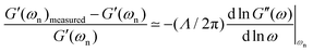 | (7a) |
| |  | (7b) |
where Λ is the measured logarithmic decrement in the damped oscillatory response. As discussed before, for most viscoelastic solids the free-vibration response is underdamped and consequently Λ < 1. In this limit we can also approximate the logarithmic decrement by 2π/(ωnτvis) and show that Λ/π ≃ tanδ(ωn).61 Thus, as discussed by Struik,61eqn (7a) and (7b) clearly show that for solid-like viscoelastic materials (which have small values of tanδ < 1) the relative errors in measurements are negligible. The relative errors are also substantially smaller for ranges of resonance frequencies over which the viscoelastic moduli look relatively flat on a log–log scale. This is true for many fiber samples, as shown for example in Fig. 5(b and d). The viscoelastic moduli look flat for typical test fibers and, as indicated in eqn (7a) and (7b) this observation, combined with the small values of tanδ guarantee low values of error in our measurements of viscoelastic moduli.
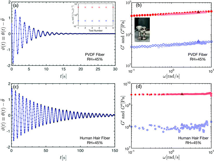 |
| | Fig. 5 (a) Torsional pendulum free oscillation data for a Trilene XTFS4-15 fishing line fiber (diameter 2R = 200 μm) made of poly(vinylidene fluoride). The inset shows the calculated values of ωn and 1/τvis from six different tests on the fishing line fiber. (b) An oscillatory torsion test performed on the same fishing line fiber mounted on an ARES strain-controlled rheometer. The filled and hollow circles show, respectively, the elastic and loss moduli from a discrete frequency sweep test. The filled and hollow squares show, respectively, the calculated elastic and loss moduli from a single test performed with an OWCh (Optimally Windowed Chirp) signal with ∼3 s duration. The filled and hollow triangles show the results from the torsional pendulum measurement (plotted in (a)) at the natural oscillation frequency of the fiber-pendulum assembly (ωn). (c) Torsional pendulum underdamped oscillation data for a human hair (diameter 2R = 66 μm) measured at temperature T = 25 °C and relative humidity RH = 45%. (d) An oscillatory torsion test performed on the same hair fiber mounted on an ARES strain-controlled rheometer. The filled and hollow circles show respectively the elastic and loss moduli from a discrete frequency sweep test. The filled and hollow squares show respectively the calculated elastic and loss moduli from a single test performed with an OWCh (Optimally Windowed Chirp) signal with ∼14 s duration. The filled and hollow triangles show the results from the torsional pendulum measurement (plotted in (c)) at the given natural oscillation frequency of the fiber-pendulum (ωn). | |
The findings embodied in eqn (7a) and (7b)61 rationalize the observed accuracy in free-oscillation measurements performed on viscoelastic solids (which were often based on analysis based on an approximate equation of motion such as eqn (6)). As Markovitz59 notes, it appears that when the system loss is sufficiently small, the exact and approximate solutions are experimentally indistinguishable. Knowing that for all the tested fibers (and for many other natural and industrial materials) the fibrous samples have dominantly solid-like characteristics where tanδ ≤ 0.2–0.3, we also use the approximate analysis for our torsional free-vibration measurements which guarantees an upper bound for our errors below 10–15%. Using eqn (6), similar to our analysis for the Kelvin–Voigt model, we deduce that for the damped oscillation torsion test,  and
and  . Thus, for a long thin fiber composed of a general viscoelastic solid, measuring the natural resonant frequency ωn and the viscous decay rate 1/τvis enables us to find the values of viscoelastic moduli at the natural resonant frequency:
| |  | (8a) |
| |  | (8b) |
These results look similar to the expressions provided for a Kelvin–Voigt model (
eqn (5a) and (5b)). However, we emphasize that in deriving the final expressions for a general linear viscoelastic solid (
eqn (8a) and (8b)) we did not assume any specific constitutive equation and the only assumption behind our approximations was that the fiber material has a solid-like viscoelastic nature with a relatively low value of tan
δ(
ωn) and that the deformation remains small enough to be in the linear viscoelastic limit. Without any prior knowledge about the fiber, the validity of the mentioned assumption can be checked from direct inspection of the measured logarithmic decrement
Λ ≃ π
tan
δ(
ωn) during a torsional free-vibration test.
3.3 Torsional measurements performed on test fibers
We now apply these analytical tools on recorded data from a series of torsional pendulum tests which were performed on two different fibers. We calculate the corresponding values of viscoelastic properties and compare our torsional pendulum measurements with results from standard rheological tests that were performed on the same fibers.
3.3.1 Description of the test fibers and the rheometer.
A segment of a commercial fishing line (Trilene XTFS4-15) with diameter D = 2R = 200 μm and length L = 6.2 cm was cut and used as a test fiber. This synthetic sample is a homogeneous monofilament strand made of poly(vinylidene fluoride). We also performed a series of tests on strands of Caucasian human hair (provided by L'Oreál). Torsional pendulum measurements were carried out on a segment of Caucasian human hair with average diameter D = 2R = 66 μm and length L = 7.4 cm. In addition to the torsional pendulum experiments, we also performed a series of complementary mechanical tests on a strain-controlled rheometer (ARES-G2 from TA Instruments).
3.3.2 Rheological test protocols.
As with any linear system identification problem, we can also measure linear viscoelastic properties of the fiber by directly imposing a time-varying input linear deformation signal with a sufficiently small strain amplitude and recording the resisting stress/torque output signal of the fiber. This is the basis of a wide range of rheometric test protocols used for studying different materials.63 In a commercial strain-controlled rheometer the material is confined between two test fixtures (e.g. it is often sandwiched between two circular plates). One of the test fixtures is mounted on a motor which applies the deformation and the other fixture is connected to a torque transducer. The user applies a small deformation to the material as an input strain signal γ(t) and simultaneously records the output stress response σ(t) through torque measurements. Assuming a linear response is confirmed, the ratio of these two signals in the Fourier domain determines the linear viscoelastic moduli of the material:63| |  | (9) |
where G*(ω) is the complex modulus of the bulk material under investigation and the tilde indicates the Fourier transform. The elastic and loss moduli, G′ and G′′, can subsequently be extracted as the real and imaginary part of the complex modulus, i.e., G′(ω) = ℜ{G*(ω)}, G′′(ω) = ℑ{G*(ω)}. While this technique is often used for liquid samples or disc-like solid/gel samples, the exact same principles apply to high aspect ratio geometries such as fibers or strands. Indeed many early studies used this technique in characterizing the mechanical properties of different synthetic and natural fibers.14,33
The input strain signal can be of any functional form as long as deformations are bounded within the linear range. However, most studies have used a discrete frequency protocol which, for measuring moduli at each individual frequency ωi, uses a monochromatic sinusoidal deformation signal γ(t) =γ0sin(ωit). To calculate the moduli, we can either use eqn (12) or decompose the phase-shifted output stress signal into in-phase σ′(t) = G′(ωi)γ(t) and out-of-phase σ′′(t) = G′′(ωi)(t) components. Apart from the simplicity of implementation, this method is also more accurate than many other signals due to the known benefits of noise filtering in the spectral domain.64 However, the minimum measurement time ti for obtaining data at an individual frequency is ti = 2π/ωi and consequently the overall test duration for completing a frequency sweep over a range of individual frequencies can add up to become a relatively large value. This can be problematic specifically for time-evolving or “mutating” materials (such as a drying coating on a fiber) where rapid measurements of moduli values that are changing systematically with time is crucial. Thus, we also performed a series of tests with a novel input strain signal that is based on exponential chirps, i.e., sine sweeps with constant amplitude and an instantaneous frequency that increases exponentially in time. As Geri and coworkers65 have recently shown, chirp signals suffer from spectral leakage and despite their ability to provide rapid measurements of the system response, the final reported values of moduli can be inaccurate. To circumvent this issue and to minimize the spectral leakage error, Geri and coworkers superposed a smooth window function onto the input signal and reduced the leakage error significantly.65,66 Inspired from their study, we also used this new test protocol known as the Optimally Windowed Chirp (OWCh) signal in our measurements.
The test fibers are attached to acrylic discs in the torsional pendulum setup. The dimensions of these discs were chosen such that we can also mount them on the ARES rheometer with conventional fixtures. Both discrete frequency and OWCh signal protocols were used in our torsional measurements on the ARES-G2 rheometer and the amplitude of angular oscillations for the rotating disc, in both protocols, is chosen in a manner that the strain amplitude is γ0 = Rϑ0/L = 0.3%. In the following section we provide a quantitative comparison between the results from different measurements: free-vibration tests with the torsional pendulum setup and torsional tests on the rheometer using either discrete frequency or OWCh signal protocols.
3.3.3 Results from different techniques.
For both test fibers, the torsional pendulum tests were performed in room temperature and humidity conditions (25 °C and 45% relative humidity). As discussed earlier, the free oscillation of each fiber is recorded with a camera and the sequence of images are analyzed to develop the underdamped torsional response. Fig. 5(a and c) show respectively the resulting oscillation profiles for the fishing line and the human hair fiber. As shown in the inset plot of Fig. 5(a), the measured values of natural resonant frequency and viscous decay rate do not depend on initial test conditions and remain unchanged for the same fiber during multiple different tests. Based on the measured values of oscillation parameters (ωn, τvis), we calculate the viscoelastic moduli of the fiber at the natural resonant frequency (G′(ωn),G′′(ωn)) through eqn (8a) and (8b). The filled and open triangles, in Fig. 5(b and d), respectively show the calculated storage and loss moduli from the torsional pendulum tests for both fibers. Results from torsional tests performed under forced oscillation conditions on the rheometers are also presented in Fig. 5(b and d) for the fishing line and the human hair respectively. It is clear that, for both fibers, the results from discrete oscillatory frequency tests (circles) and OWCh signal protocols (squares) agree with each other over a wide range of frequencies. Furthermore, at the resonance frequencies, both of these measurements are in good agreement with the values of the storage and loss moduli computed from unforced oscillation tests with the torsional pendulum. Vinogradov and Holloway67 have measured the Young's modulus of PVDF fibers and reported an approximate value of EPVDF ≃ 2.4–2.7 GPa, which, assuming a Poisson ratio of 0.5, corresponds to an approximate elastic shear modulus of GPVDF ∼ 8 × 10⁸–9 × 10⁸ Pa. This reported value is very close to the values of G′ measured in our studies on the PVDF fishing line (see Fig. 5(b)). Similarly, Wolfram and Albrecht have measured the torsional properties of hair fibers with different thicknesses at a relative humidity of 65% and reported an approximate torsional modulus of GHair′(ω = 0.9 rad s−1) ≃ 1 × 10⁹ Pa and a logarithmic increment of Λ ≃ 0.17 which corresponds to a phase angle given by tanδ ≃ Λ/π ≃ 0.05. Knowing that our measurements of human hair properties were performed in a less humid environment, we expect a slightly higher value for elastic modulus and a slightly lower value for the loss tangent which agrees well with our reported values of G′(ω = 0.9 rad s−1) ≃ 3 × 10⁹ Pa and tanδ(ω = 0.9 rad s−1) ≃ 0.03 in Fig. 5(d).
These results confirm that we can use conventional rheometers to measure the viscoelastic properties of thin biological fibers such as human hair. Simple calculations show that even for a thin fiber R ≃ 66 μm the modulus of the material within the hair fiber is large enough that linear oscillations with amplitude γ0 ≃ 0.3% generate torque signals with amplitudes as high as 3 μN m. This torque level is ∼60 times higher than the reported values for the minimum torque limit of a strain-controlled rheometer such as the ARES-G2.¶
The fact that results from a simple free-vibration test agree well with measurements from more sophisticated rheometer-based techniques is a promising indicator for future applications. It is of course true that with a torsional pendulum measurement we only probe the viscoelastic properties at the resonant frequency which can be varied by the radius or density of the disc. However the practical simplicity and low cost of a pendulum test can not be matched by any conventional rheometer or mechanical analyzer. This can be particularly useful for tests on biomaterial samples where necessary field measurements may not have the luxury of access to conventional rheometers. Regarding torsional measurements with the rheometer, we should also point out that while a discrete frequency sweep took around 30 minutes to gather the data over the measured range of frequencies, the OWCh protocol took only 14 s to obtain accurate measurements over a comparable range of frequencies. This feature of compact time-varying signals such as chirps in system identification is of great future utility for tests on time-varying or mutating material systems such as gelling, drying and or crosslinking coatings on fibers.
3.4 Viscoelastic properties of fiber coatings
Viscoelastic coatings are commonly applied to many synthetic and natural fibers. Measuring the effective bulk properties of the viscoelastic coatings and quantifying their contributions to changes in the overall mechanical properties of the coated fiber assembly is crucial in many different applications. An important aspect of torsional deformations is the fact that stresses from the outer shell regions in each circular cross-section of the fiber contribute more to the net torque than stresses from the internal core of the fiber. This means that for fibers with radial gradients in material properties torsional measurements are more sensitive to the viscoelastic properties of the outer layers than the inner ones. Torsional measurements in a coated fiber assembly are therefore strongly affected by the coating properties which provides a convenient platform for systematic characterization of the coating properties. Based on this simple idea, we first revisit some of the geometrical features of our torsional pendulum tests and then apply them to our analysis of free vibration measurements for fibers that were coated with viscoelastic hydrogels.
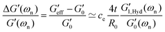
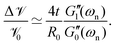
As eqn (8a) and (8b) show, in calculating the effective viscoelastic properties from the measured torsional oscillation parameters we have a strong dependency on the diameter of the fiber that scales as ∼D−4. Different viscoelastic coatings corresponding to different chemical formulations can thus lead to a very large change in the effective viscoelastic response of the entire fiber-disc torsional pendulum system. To understand these changes, we seek to define appropriate new metrics that can quantify the overall contribution of the coating to the mechanical properties of the entire coated fiber assembly. By rearranging geometrical terms in eqn (8a) and (8b) we define two measures of the overall mechanical energy exchange in a fiber undergoing damped torsional oscillations:
| | 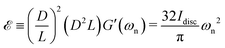 | (10a) |
| | 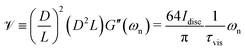 | (10b) |
where
![[scr E, script letter E]](https://www.rsc.org/images/entities/char_e140.gif)
and
![[scr V, script letter V]](https://www.rsc.org/images/entities/char_e149.gif)
are, respectively, defined as scales for the stored elastic energy and the viscously-dissipated energy in a fiber during damped free oscillation. These new measures can be directly connected to the measured parameters of the oscillation test, namely the natural resonant frequency and viscous decay rate. The parameters defined in
eqn (10) are essentially products of a geometrical aspect ratio (
D/
L)
2 with the cylindrical volume of the fiber
D2L and the corresponding storage (elastic) or loss (viscous) moduli of the fiber and any surface coating. The fact that the viscoelastic modulus of a material can also be expressed as an energy density indicates that these proposed definitions provide us with appropriate scales for the different contributions to the total energy balance within the fiber during damped torsional vibration. Thus, these new energy-based metrics are helpful for quantifying and discriminating between viscoelastic contributions of fiber coatings in many situations where thin coatings, with different chemical composition but similar thicknesses, are applied on identical fibers.
3.4.1 Calcium alginate coatings.
In order to demonstrate the application of torsional pendulum measurements in quantifying viscoelastic properties of thin fiber coatings, we performed tests using three different hydrogel coatings that were applied to three initially identical segments of a fishing line (i.e. fibers with same values D and L). The hydrogel coatings are calcium alginate gels that were made by a two step dip-coating process on the fiber. First we dip-coated the fiber with a concentrated alginate solution and then passed the fiber through a reservoir of CaCl2 solution (1 M). Three different alginate solutions were prepared by dissolving different concentrations (8%, 6% and 4 wt%) of sodium alginate (NaALG CAS: 9005-38-3 purchased from Sigma Aldrich) in DI water. Separate rheological measurements were performed on these fully hydrated alginate gels that are not shown here. After exposure to CaCl2 and gelation, the plateau shear modulus Gp of fully hydrated alginate gels increases monotonically with alginate concentration (Gp(4%) = 0.20 MPa, Gp(6%) = 0.42 MPa, and Gp(8%) = 0.65 MPa). Three identical fibers (PVDF fishing line with diameter D0 = 2R0 = 200 μm) were coated with these three different hydrogels and left to dry in air at room temperature for one hour.|| The final measured coating thickness of the dried hydrogel coatings is 11 μm for all three different alginate coatings.
3.4.2 Tensile tests and torsional pendulum experiments.
Before coating, a torsional pendulum test was performed on each test fiber. After dip coating, the coated fiber was again tested using the torsional pendulum setup. Subsequently the coated fiber-disc assembly was mounted on the ARES-G2 rheometer and a tensile test was performed on the coated fiber. The coated fiber was stretched within the linear limit of elongational strains. A second tensile test was also performed after the removal of the coating. This enabled us to record the tensile and torsional behavior of the fiber both with, and without, the viscoelastic hydrogel coating.
Fig. 6(a and b) show the changes in each of the effective storage and dissipation energy measures, defined by eqn (10a) and (10b), between the coated and uncoated fibers for all three alginate coatings. It is clear that, for similar coating thicknesses, both the stored elastic energy and viscously dissipated energy increase with the concentration of alginate in solution (plotted in Fig. 6(a)) and consequently with the viscoelastic shear moduli of the alginate coating material (plotted in Fig. 6(b)). For each hydrogel coating, the values of the complex modulus were measured separately in a hydrated state on the rheometer over a wide range of frequencies and corresponding values at the resonant frequency G1,Hyd′′(ωn), G1,Hyd′(ωn) are used in Fig. 6(b).** As expected, increasing the concentration of alginate leads to larger values of the viscoelastic moduli in the final coating. As Fig. 6(b) shows, the enhancement of the overall viscoelastic energy measures for the coated fibers are linearly proportional to the viscoelastic moduli of the coating. In Section 5.1 of Appendix A we develop a simple 2 layer core/shell analytical model and show that the enhancement in these energy measures for a uniformly coated fiber depend on both the viscoelastic modulus and the thickness of the coating. For thin coatings (t ≪ R0), normalized values of these enhancements can be approximated by (see Section 5.1 and eqn (20a) and (20b)):
| |  | (11a) |
| |  | (11b) |
where
t and
R0 are the coating thickness and the radius of the uncoated fiber respectively. Viscoelastic properties of the dried coating and the core fiber material are represented by

and

respectively. The suggested approximation of our analytical model and the observed trend in energy measures can be also understood with a simple physical argument based on the relative scales of viscoelastic energies involved. For an uncoated fiber the viscoelastic energy measures (per unit length) scale as the cross-sectional area multiplied by the respective viscoelastic moduli;
i.e.
and
. Similarly, the incremental viscoelastic energies in the thin coating (per unit length) scale as
and
. Thus the normalized values of enhancements in viscoelastic energy measures scale as
and
.
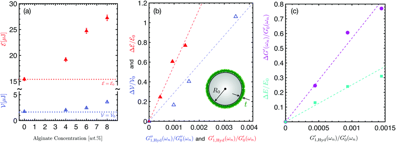 |
| | Fig. 6 (a and b) Results of torsional pendulum tests done on identical Trilene XTFS4-15 fishing line fibers (uncoated diameter 2R0 = 200 μm) made of poly(vinylidene fluoride) coated with three different alginate hydrogel coatings. Measurements represent both the uncoated and the coated fibers where three different alginate coatings with initial alginate concentrations of 4, 6 and 8 wt% in solution were used. In (a) we show the increase of both the stored elastic energy and viscoelastically dissipated energy in the coated fiber combination versus the concentration of the alginate hydrogel coating solution. Panel (b) shows the normalized incremental change in the viscoelastic energy measures of the coated fiber assembly versus the measured shear viscoelastic moduli of the alginate hydrogel (measured on the rheometer in a fully hydrated state in a water bath) normalized by the viscoelastic moduli  of the uncoated fiber. Filled red and blue open triangles represent measures for stored elastic energy and viscoelastically dissipated energy respectively. Dashed lines show the corresponding predictions of the theoretical model as described by eqn (12a) and (12b). (c) The apparent increase in the torsional shear modulus of the uncoated fiber. Filled red and blue open triangles represent measures for stored elastic energy and viscoelastically dissipated energy respectively. Dashed lines show the corresponding predictions of the theoretical model as described by eqn (12a) and (12b). (c) The apparent increase in the torsional shear modulus 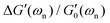 (filled magenta circles) and the increment in the tensile elastic modulus ΔE/E0 (filled cyan squares) measured respectively by the torsional pendulum and tensile tests. Dashed lines show the corresponding predictions of the theoretical model as described by eqn (13a) and (13b). (filled magenta circles) and the increment in the tensile elastic modulus ΔE/E0 (filled cyan squares) measured respectively by the torsional pendulum and tensile tests. Dashed lines show the corresponding predictions of the theoretical model as described by eqn (13a) and (13b). | |
Knowing that the viscoelastic moduli of the alginate coatings are larger in the dried state compared to their corresponding values in the fully hydrated state, these approximations (eqn (11a) and (11b)) can also be rewritten as:
| | 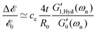 | (12a) |
| | 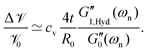 | (12b) |
where
and
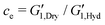
are the drying coefficients for the elastic storage modulus and the viscous loss modulus respectively. As shown in
Fig. 6(b), these approximations successfully fit the measured data with drying coefficients
ce = 1092 and
cv = 557 used as fitting parameters. Thus, simple torsional pendulum measurements can readily measure the incremental changes in the viscoelastic properties of fibers coated with a thin film, as well as the systematic changes resulting from increasing the polymer concentration in the coating.
We also performed a series of tensile tests on all the fibers, both with and without the hydrogel coatings. In each test, we stretched the fiber slowly and recorded the axial force versus the stretched length of the fiber. Nominal values of the engineering strain and stress are calculated based on the initial length L0 and cross-sectional area A0 of the uncoated fiber. All the tensile tests were stopped before maximum axial strain values of εz ≃ ΔL/L0 ≤ 3% to ensure that we did not cause any irreversible plastic nonlinear deformations. This was also checked by elastic unloading of the fibers. The effective elastic tensile modulus of the fiber Eeff was calculated by linear regression to the measured stress–strain curve. Since, for all cases, the engineering stresses are calculated based on the cross-section of the uncoated fiber, the effective tensile modulus of the coated fiber should clearly be higher than the corresponding value for the uncoated fiber. Similarly, we use the measured values of natural resonant frequency from torsional pendulum tests and, using eqn (8a), calculate the shear modulus Geff′(ωn) of the coated and uncoated fibers based on the geometrical dimensions of the uncoated fiber. This enables us to measure the relative increase in the apparent tensile and torsional moduli due to the coating regardless of its hydration state or the axial uniformity of the coating. Fig. 6(c) shows the relative increase for both the elastic tensile modulus ΔE/E0 = [Eeff − E0]/E0 (measured from the tensile test) and elastic shear modulus  (measured from the torsional pendulum test) where the data is normalized based on the tensile and shear moduli of the uncoated fiber, E0 and
  respectively.
As expected, Fig. 6(c) shows that the relative amplification in both apparent tensile and shear moduli for the coated fiber assembly increases with the modulus (and concentration) of the alginate hydrogel coating. However, for all three coatings, the torsional pendulum measurements show a higher relative increase in the effective shear modulus of the coated fiber than the relative increase measured in the apparent tensile modulus. It is thus clear that torsional oscillation measurements are indeed more sensitive than tensile tests in quantifying the effective incremental mechanical contributions of a thin viscoelastic coating applied to a thin fiber. As discussed in Sections A.1 and A.2 of Appendix A, this is a direct consequence of the difference in the geometrical scaling of the incremental stress contributions, across the fiber's cross-section, during a torsion or tension test. In tension, the stresses sum uniformly, over the entire cross-section of the fiber, to balance the applied axial load whereas in torsion the stresses from the outer regions contribute more to the net resistive torque exerted by the fiber. Thus, when compared to tensile tests, torsional measurements show higher sensitivity to the properties of the outer layers such as coatings. In fact one can do an explicit analysis for a cylindrical fiber with initial radius R0 and shear and tensile moduli G0 and E0 that has a uniform coating applied (with shear and tensile moduli  and E1 respectively) that increases the radius from R0 to R1. For such a fiber the apparent shear modulus, which can be measured in a torsional test, increases by
  while the apparent tensile modulus increases by ΔE = E1[(R1/R0)2 − 1]. For a thin coating where t = (R1 − R0) ≪ R0 we can approximate these analytic expressions at leading order as
  and ΔE/E1 ≃ (2t/R0)[E1/E0] suggesting that the torsional measurements are at least twice as sensitive to the coating properties of a thin coating when contrasted with tensile measurements. Fig. 6(c) shows a similar trend; for all of the tested coatings the torsional measurements are a factor of two more sensitive to the coating properties than the tensile tests. Knowing that both the shear and tensile moduli in the fully dried coating are larger than their corresponding values in the hydrated state (i.e.
 with ce ≫ 1) we provide an analytical approximation for the increase in the effective values of measured shear and tensile moduli:
| |  | (13a) |
| | 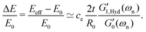 | (13b) |
Fig. 6(c) shows that these analytical asymptotic predictions agree very well with our measurements. We have consistently used a value of
ce = 1092 for the drying coefficient that is identical to the value determined from the model fits to measured data in
Fig. 6(b). Both the analytical approximations and the measured data indicate that the apparent shear moduli measured in torsion is a factor of two more sensitive to coating properties than the tensile moduli measured in a tension test.
We also emphasize that an additional critical aspect of a viscoelastic coating is its contribution to the dynamic properties of the fiber. In contrast to an axial tension test, a free oscillation test also provides direct insight into the changes to the energy dissipating properties of the fiber through the value of τvis measured for the coated fiber. Furthermore, a torsional pendulum apparatus can also probe the dynamic properties of the fiber at different frequencies by using different discs with varying moments of inertia to vary ωn. This however is not the case for a tensile test where the test is often performed at quasi-static stretch rates. We note that a dynamic tensile test such as DMA (Dynamic Mechanical Analysis) can also report both tensile storage and loss moduli E′ and E′′. However, in addition to being more expensive than a torsion pendulum setup they also show less sensitivity to coating properties than torsional measurement due to the geometrical factor calculated above. Furthermore, humidity, temperature and pH can all change the properties of the coatings applied to different fibers and thus affect the overall viscous dissipation. Unlike conventional tensile tests, a torsional pendulum measurement can quantify these effects with a simple and low-cost test.
4 Conclusions
Free torsional oscillations have been used extensively for characterizing viscoelastic properties of different fiber materials. In this paper we applied this technique to measure mechanical properties of both synthetic and natural fibers and the changes induced by thin polymer coatings. The simplicity of the setup and the data acquisition process makes this measurement technique readily accessible for researchers from a wide variety of different backgrounds and industries such as textile, cosmetics, biology and engineering. We also presented a rational framework that describes how the measured parameters in a damped torsional oscillation test are connected to the underlying viscoelastic properties of the fiber. Using both natural and synthetic fibers we measured the dynamic viscoelastic moduli and showed that our torsional pendulum results agree with direct torsional measurements performed on a strain-controlled rheometer. The high numerical values of the slopes of the linear relationships shown in Fig. 6(b and c) illustrate the high sensitivity of the technique to application of thin viscoelastic coatings even when the modulus of the coating is smaller than that of the primary fiber. Finally we showed that for fibers with thin applied coatings, torsional measurements are more sensitive to the viscoelastic properties of the coating. As a proof of concept, for a test fiber coated with three different alginate hydrogels, we showed that the torsional pendulum measurements are at least twice as sensitive to the coating properties as tensile mechanical measurements. Viscoelastic properties of soft fibers and coatings play a key role in many biological and industrial processes and the experimental and analytical framework outlined in this study can help researchers in characterizing the effective changes to viscoelastic material characterization of coated fibers using simple and accurate measurements.
Conflicts of interest
There are no conflicts to declare.
Appendix A: viscoelastic response of a coated fiber in torsional oscillations and axial deformations
In this appendix we consider a coated fiber that has a viscoelastic core with uniform radius R0 and spatially uniform complex viscoelastic modulus  throughout its length L. We assume that a uniform coating with thickness t covers the core from R0 to R1 = R0 + t. The coating material is also characterized through its own complex viscoelastic modulus
  . As shown in Fig. 7, the optically measured profile of a typical fishing line fiber before and after the coating verifies the assumption of uniform coating thickness along the length of the fiber.
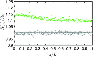 |
| | Fig. 7 Measured profile of the commercial fishing line (Trilene XTFS4-15) with diameter D0 = 2R0 = 200 μm and length L = 6.2 cm without (gray data) and with (green data) a dried hydrogel alginate coating. Solid lines show the mean values calculated based on the average over the entire length of the fiber. The variation in coating thickness is less than 10 μm along the whole length of the fiber. | |
A.1 Torsional oscillations
As shown in the main text, the time-evolving value of the overall torque (t) remains constant throughout the fiber and is balanced by the geometrical distribution of viscoelastic stresses in each cross-section. Thus for a coated fiber:| | 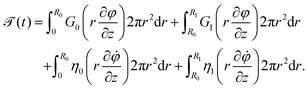 | (14) |
where the modulus values are set by the elastic moduli at the resonant frequency  ,
,  , and similarly the viscosity values are proportional to the loss moduli of each material at the resonant frequency
 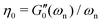 ,
,  . We use separation of variables to describe the twist angle as a product of two separable spatial and temporal functions ϕ(z, t) = f(z)g(t). Consequently, we write the balance of torque in each cross-section as:
| | 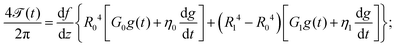 | (15) |
which suggests that a constant value of torque requires a constant value for df/dz along the length of the fiber. This indicates that, similar to the studied case of a single uniform fiber, for a uniformly coated fiber the twist angle varies linearly from φz=0 = 0 at the fixed end to φz=L = ϑ(t) at the free end of the fiber. This enables us to find a simplified expression for the value of torque in the coated fiber:| | 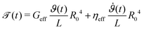 | (16) |
where the effective viscoelastic properties are set by the viscoelastic and geometrical properties of the coated fiber:| | 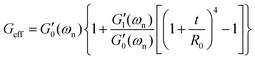 | (17a) |
| | 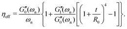 | (17b) |
By rearranging terms and writing an overall equation of motion for the disc we find that both the resonant frequency and the viscous decay rate of the coated fiber (ωn and 1/τvis) are enhanced significantly when compared to their corresponding values for the uncoated fiber (ωn(0) and 1/τvis(0)):| | 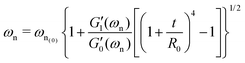 | (18a) |
| | 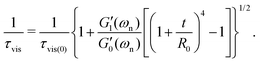 | (18b) |
Using the definition of the overall mechanical energy measures in a torsionally oscillating fiber (eqn (10)), we can also provide new expressions for the enhancement of stored elastic energy and the viscously-dissipated energy in the coated fiber:| |  | (19a) |
| | 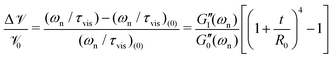 | (19b) |
which in the limit of t/R0 ≪ 1 (thin coatings) can be approximated as:| | 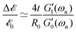 | (20a) |
| |  | (20b) |
A similar approximation for the viscoelastic moduli suggests that the effective elastic modulus of a coated fiber is larger than the uncoated fiber by| | 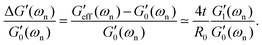 | (21) |
This shows that in a torsional test the measured elastic modulus of the coated fiber is enhanced by both the ratio of the elastic moduli of the coating and the initial fiber  and also by four times the geometrical ratio of coating thickness over core radius 4t/R0.
A.2 Axial deformations
We now perform a similar analysis for the coated fiber in axial deformations during a linear tensile test. The axial force ![[scr F, script letter F]](https://www.rsc.org/images/entities/char_e141.gif) is constant throughout the length of the fiber and is balanced with the spatial distribution of tensile stresses in each circular cross-section of the coated fiber:
is constant throughout the length of the fiber and is balanced with the spatial distribution of tensile stresses in each circular cross-section of the coated fiber:| | 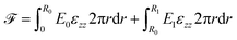 | (22) |
where E0 and E1 are the values of elastic Young's moduli for the core and the coating material respectively and εzz is the axial component of the strain tensor. This expression for axial loading can be simplified into| |  | (23) |
where| | 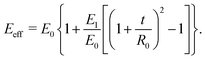 | (24) |
The measured value of the effective elastic Young's modulus Eeff is thus enhanced in the coated fiber by a factor of| |  | (25) |
which can be approximated by ΔE/E0 ≃ (2t/R0)(E1/E0) for thin coatings (t/R0 ≪ 1). Thus, if the Poisson ratio is similar between the coating and the core material we can approximate the enhanced value of the tensile modulus (Young's modulus) by| |  | (26) |
This approximation shows that in axial elongation during a tensile test, similar to torsional deformations, the measured Young's modulus of the coated fiber is enhanced by a factor that combines both material and geometrical properties. Similarly, this factor is set by the ratio of the elastic moduli of the two materials  . However, the geometrical ratio 2t/R0 is reduced by a factor of two compared to the torsional analysis leading to eqn (21).
Safety statement
All experiments were performed in compliance with relevant safety laws at MIT and followed specific institutional guidelines. Safety representatives of HML (Hatsopoulos Microfluids Laboratory) and the Mechanical Engineering Department at MIT approved the experiments. We used Caucasian Natural Straight hair samples in this study and all the hair samples were purchased from a commercial hair vendor: International Hair Importers & Products, Inc. (NY, USA).
Acknowledgements
The authors greatly appreciate early discussions with Dr Gustavo S. Luengo and are thankful for his learned advice regarding tests on human hair samples. We also thank L'Oreál Research & Innovation for the financial support and also thank anonymous reviewers for their interest in our work and constructive feedback.
References
- H. Leaderman, Text. Res., 1941, 11, 171–193 CrossRef CAS.
- G. N. Merberg and J. A. Harrington, Appl. Opt., 1993, 32, 3201–3209 CrossRef CAS PubMed.
-
C. R. Robbins, Chemical and physical behavior of human hair, Springer, 1994, pp. 299–370 Search PubMed.
- M. Wang, H.-J. Jin, D. L. Kaplan and G. C. Rutledge, Macromolecules, 2004, 37, 6856–6864 CrossRef CAS.
- C. Holland, A. E. Terry, D. Porter and F. Vollrath, Nat. Mater., 2006, 5, 870–874 CrossRef CAS PubMed.
- N. Holten-Andersen, G. E. Fantner, S. Hohlbauch, J. H. Waite and F. W. Zok, Nat. Mater., 2007, 6, 669–672 CrossRef CAS PubMed.
- I. Agnarsson, A. Dhinojwala, V. Sahni and T. A. Blackledge, J. Exp. Biol., 2009, 212, 1990–1994 CrossRef PubMed.
- V. Sahni, T. A. Blackledge and A. Dhinojwala, J. Adhes., 2011, 87, 595–614 CrossRef CAS.
- V. Sahni, D. V. Labhasetwar and A. Dhinojwala, Langmuir, 2012, 28, 2206–2210 CrossRef CAS PubMed.
- M. H. Godinho, J. P. Canejo, G. Feio and E. M. Terentjev, Soft Matter, 2010, 6, 5965–5970 RSC.
- L. J. Wolfram and M. K. O. Lindemann, J. Soc. Cosmet. Chem., 1971, 22, 839–850 CAS.
-
J. Hu, Shape Memory Polymers and Textiles, Elsevier, 2007 Search PubMed.
- T. Bornschlögl, L. Bildstein, S. Thibaut, R. Santoprete, F. Fiat, G. S. Luengo, J. Doucet, B. A. Bernard and N. Baghdadli, Proc. Natl. Acad. Sci. U. S. A., 2016, 113, 5940–5945 CrossRef PubMed.
- H. Bogaty, J. Soc. Cosmet. Chem., 1966, 18, 575–590 Search PubMed.
- D. J. Plazek, M. Vrancken and J. W. Berge, Trans. Soc. Rheol., 1958, 2, 39–51 Search PubMed.
- G. T. Gillies and R. C. Ritter, Rev. Sci. Instrum., 1993, 64, 283–309 CrossRef.
-
C. S. Gillmor, Coulomb and the evolution of physics and engineering in eighteenth-century France, Princeton University Press, 2017 Search PubMed.
- H. Cavendish, Philos. Trans. R. Soc. Lond., 1798, 469–526 Search PubMed.
-
W. L. Bragg and G. Porter, The Royal Institution Library of Science: Physical Sciences, Elsevier Publishing Company, 1970 Search PubMed.
-
P. Curie, Propriétés magnétiques des corps a diverses températures, Gauthier-Villars et fils, 1895 Search PubMed.
- J. G. Lee, E. G. Adelberger, T. S. Cook, S. M. Fleischer and B. R. Heckel, Phys. Rev. Lett., 2020, 124, 101101 CrossRef CAS PubMed.
- R. S. Lakes, Rev. Sci. Instrum., 2004, 75, 797–810 CrossRef CAS.
- H. Markovitz, Trans. Soc. Rheol., 1977, 21, 381–398 Search PubMed.
- H. Streintz, Ann. Phys., 1874, 229, 387–411 CrossRef.
- F. Kohlrausch, Ann. Phys., 1876, 234, 337–375 CrossRef.
- W. Weber, Ann. Phys., 1835, 110, 247–257 CrossRef.
- W. Weber, Ann. Phys., 1841, 130, 1–18 CrossRef.
-
R. F. Macmichael, Viscosimeter, 1918 Search PubMed.
- W. H. Herschel, JOSA, 1923, 7, 335–353 CrossRef CAS.
- W. Kuhn and O. Künzle, Helv. Chim. Acta, 1947, 30, 839–858 CrossRef CAS.
- M. Mooney and R. H. Gerke, Rubber Chem. Technol., 1941, 14, 35–44 CrossRef CAS.
- K. Sittel, P. E. Rouse Jr and E. D. Bailey, J. Appl. Phys., 1954, 25, 1312–1320 CrossRef CAS.
-
H. Leaderman, PhD thesis, Massachusetts Institute of Technology, 1941.
- L. J. Hastewell and R. Roscoe, J. Sci. Instrum., 1955, 32, 96 CrossRef CAS.
- N. W. Tschoegl, Kolloid Z. Z. Polym., 1962, 181, 19–29 CrossRef.
- C. Dessi, G. D. Tsibidis, D. Vlassopoulos, M. De Corato, M. Trofa, G. D'Avino, P. L. Maffettone and S. Coppola, J. Rheol., 2016, 60, 275–287 CrossRef CAS.
-
H. Chen, PhD thesis, University of Akron, 2019.
- A. F. Lewis and J. K. Gillham, J. Appl. Polym. Sci., 1962, 6, 422–424 CrossRef CAS.
- J. Heijboer, Polym. Eng. Sci., 1979, 19, 664–675 CrossRef CAS.
-
J. B. Enns and J. K. Gillham, Polymer Characterization, American Chemical Society, 1983, vol. 203, pp. 2–27 Search PubMed.
- J. K. Gillham and J. B. Enns, Trends Polym. Sci., 1994, 2, 406–418 CAS.
- E. Kiran and J. C. Hassler, J. Supercrit. Fluids, 2019, 143, 223–231 CrossRef CAS.
-
A. P. French, Vibrations and waves, American Association of Physics Teachers, 2001 Search PubMed.
-
D. Sobel, Longitude: The true story of a lone genius who solved the greatest scientific problem of his time, Macmillan, 2005 Search PubMed.
- M. A. Lombardi, IEEE Instrum. Meas. Mag., 2011, 14, 45–51 Search PubMed.
-
T. G. Beckwith, R. D. Marangoni and J. H. Lienhard, Mechanical Measurements, Pearson Prentice Hall, 2007 Search PubMed.
- R. H. Ewoldt and G. H. McKinley, Rheol. Bull., 2007, 76, 4–6 Search PubMed.
- D. J. Wilcox, Int. J. Electric. Eng. Educ., 1978, 15, 247–265 CrossRef.
-
A. M. Cohen, Numerical Methods for Laplace Transform Inversion, Springer US, 2007 Search PubMed.
- R. Meredith, J. Text. Inst. Trans., 1954, 45, T489–T503 CrossRef.
-
A. C. Ugural and S. K. Fenster, Advanced Strength and Applied Elasticity, Pearson Education, 2003 Search PubMed.
-
C. R. Robbins and C. R. Robbins, Chemical and Physical Behavior of Human Hair, Springer, 2002, vol. 4 Search PubMed.
- R. D. Glauz, J. Polym. Sci., Part A-1: Polym. Chem., 1970, 8, 329–334 CrossRef CAS.
- C. Dessi, S. Coppola and D. Vlassopoulos, J. Rheol., 2021, 65, 325–335 CrossRef CAS.
- R. S. Rivlin and D. W. Saunders, Philosophical Transactions of the Royal Society of London. Series A, Mathematical and Physical Sciences, 1951, 243, 251–288 Search PubMed.
- V. Balbi, A. Trotta, M. Destrade and A. N. Annaidh, Soft Matter, 2019, 15, 5147–5153 RSC.
- L. E. Nielsen, Rev. Sci. Instrum., 1951, 22, 690–693 CrossRef CAS.
- N. W. Tschoegl, J. Appl. Phys., 1961, 32, 1794–1795 CrossRef.
- H. Markovitz, J. Appl. Phys., 1963, 34, 21–25 CrossRef.
- A. S. Elder, Trans. Soc. Rheol., 1965, 9, 187–212 Search PubMed.
- L. C. E. Struik, Rheol. Acta, 1967, 6, 119–129 CrossRef CAS.
-
A. J. Staverman and F. Springer-Verlag Schwarzl, Linear Deformation Behaviour of High Polymers, Berlin, Germany, 1956 Search PubMed.
-
C. W. Macosko, Rheology: Principles, Measurements and Applications, VCH Publishers Inc., New York, 1994 Search PubMed.
-
R. B. Blackman and J. W. Tukey, The Measurement of Power Spectra, Dover Publications Inc., 1958 Search PubMed.
- M. Geri, B. Keshavarz, T. Divoux, C. Clasen, D. J. Curtis and G. H. McKinley, Phys. Rev. X, 2018, 8(4), 041042 CAS.
-
J. W. Tukey, Spectral analysis of time series, 1967, vol. 25, pp. 25–46 Search PubMed.
- A. Vinogradov and F. Holloway, Ferroelectrics, 1999, 226, 169–181 CrossRef CAS.
Footnotes |
| † The light weight of the bottom disc, that is supported by the test fiber, leads to negligible axial strains εzz < 10−3% in the fiber. Consequently, the weight of the disc does not lead to significant axial deformations or variations in the cross-sectional area along the fiber. Thus, in this limit of low axial tension the weight of the disc does not affect our torsional measurements in any significant manner. |
| ‡ The torsional strain is small because R(θ0 − )/L ≪ 1 for long fibers. |
| § We assume that in the limit of small strains and twist angles the extensional strains all vanish. This may not be true for strongly rubber-like elastic materials that are also undergoing large nonlinear strains due to the Poynting effect. See for example ref. 55 and 56. |
| ¶ https://www.tainstruments.com/ares-g2/. |
| || Since the coatings were very thin, we can anticipate that the hydrogels lose most of their water content and dry significantly. We also expect that the drying process is very similar for all three tested coatings. |
| ** A disc-shaped hydrogel sample was prepared inside a Petri-dish bath of CaCl2 mounted on the rheometer and shear-oscillatory measurements were performed on the hydrogel in the fully hydrated condition using a plate–plate configuration. |
|
| This journal is © The Royal Society of Chemistry 2021 |
Click here to see how this site uses Cookies. View our privacy policy here. 
 Open Access Article
 This Open Access Article is licensed under a Creative Commons Attribution-Non Commercial 3.0 Unported Licence
 *a,
Brady
Zarket
b,
Samiul
Amin
c,
Ronak
Rughani
b,
Sivaramakrishnan
Muthukrishnan
b,
Niels
Holten-Andersen
*a,
Brady
Zarket
b,
Samiul
Amin
c,
Ronak
Rughani
b,
Sivaramakrishnan
Muthukrishnan
b,
Niels
Holten-Andersen
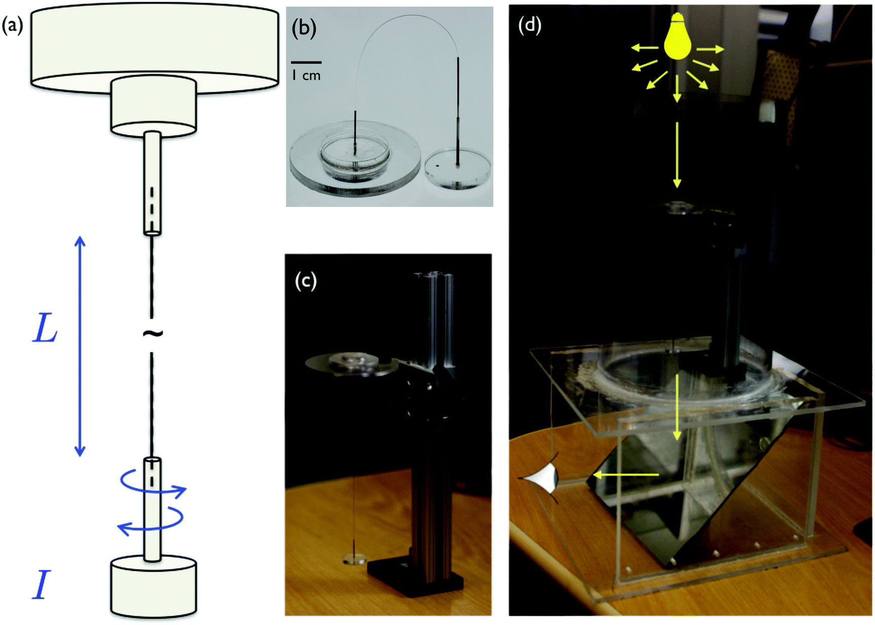
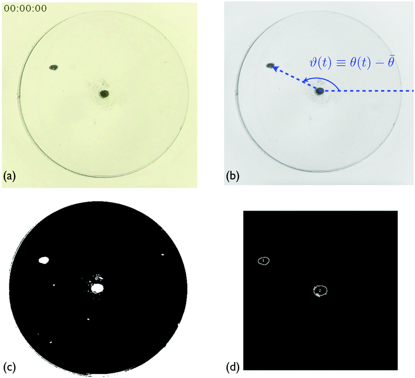
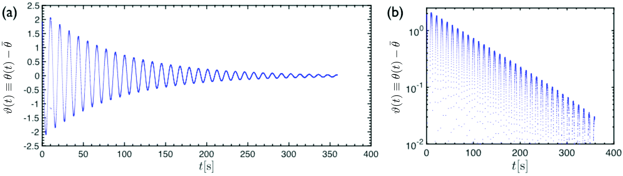
 and consequently the natural resonant frequency can be directly approximated as
  . Proceeding with this simplifying approximation, we can also find an approximate expression for the logarithmic decrement Λ ≡ ln[ϑ(t + 2π/ωn)/ϑ(t)] = 2π/(ωnτvis) ≃ 2πξ.
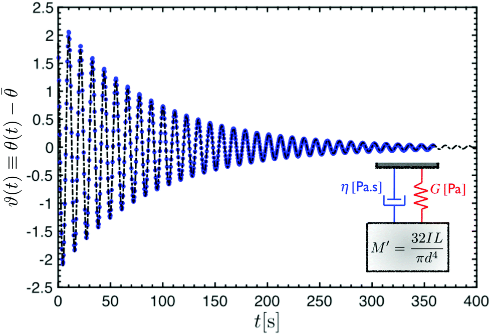
 . In a cylindrical geometry with a uniform constant cross-section diameter D = 2R, the internal torque in each cross section
 and 1/τvis = 0. Thus, by recording the oscillatory response of a torsional pendulum and finding the natural resonant frequency ωn through fitting consecutive peaks (as shown in Fig. 4), we can directly connect the measured natural resonant frequency to the shear elastic modulus of the material:
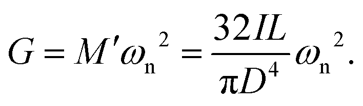
 . Similarly, the twist angle per unit length and its time derivative are constant along the axis of the cylindrical fiber, ∂φ/∂z = ϑ(t)/L and
  . The resulting shear stress distribution and net torque in each cross-section are respectively
 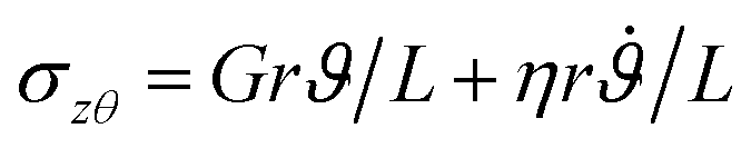 and
and 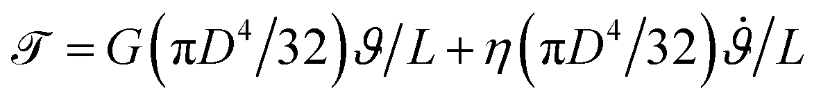 ; in each case the overall value is the sum of an elastic and a viscous contribution. Reorganizing terms, we can write the overall equation of motion for the disc:
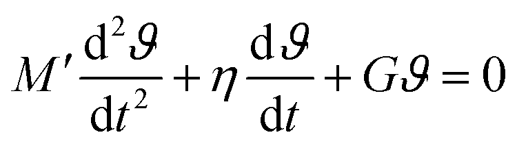
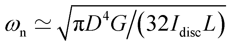 and 1/τvis = πD4η/(64IdiscL). In a freely oscillating torsional pendulum test, these expressions enable us to use the measured values of natural resonant frequency ωn and viscous decay rate 1/τvis and calculate the viscoelastic response of the material based on Kelvin–Voigt model parameters G and η:
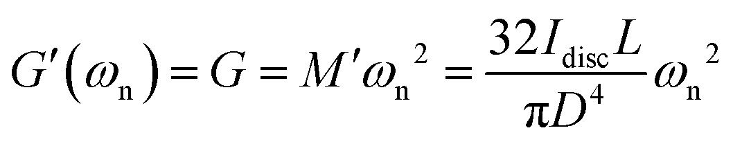
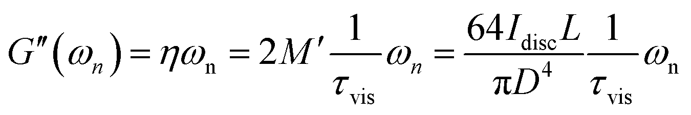
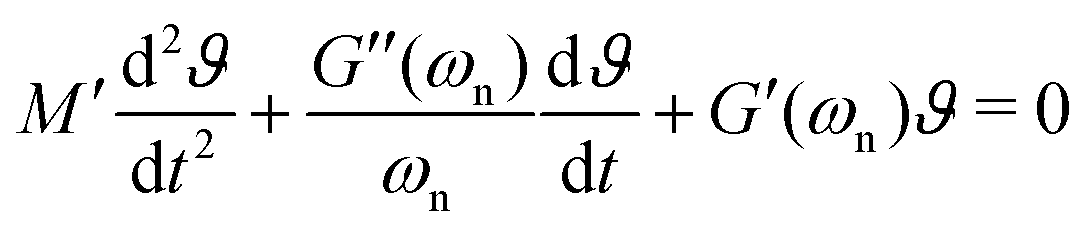

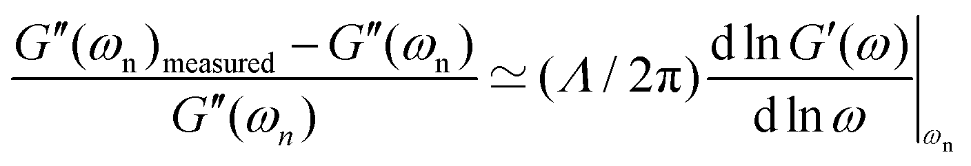

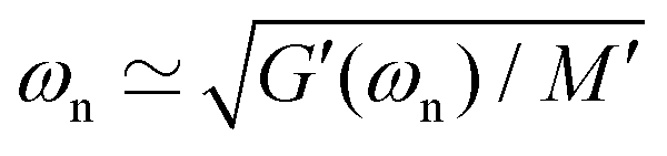 and
and 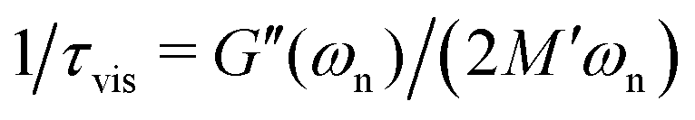 . Thus, for a long thin fiber composed of a general viscoelastic solid, measuring the natural resonant frequency ωn and the viscous decay rate 1/τvis enables us to find the values of viscoelastic moduli at the natural resonant frequency:
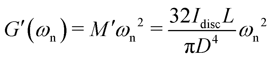
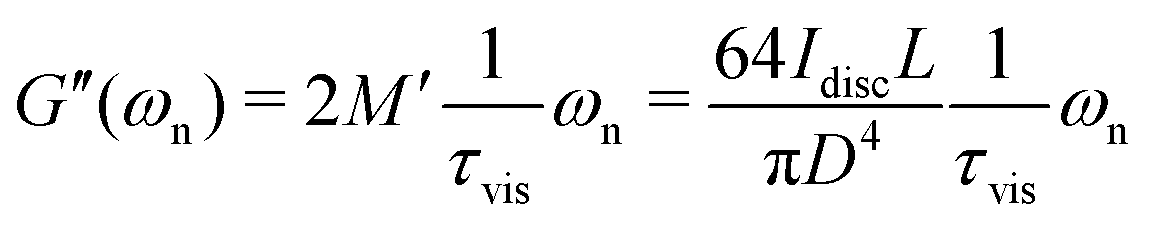
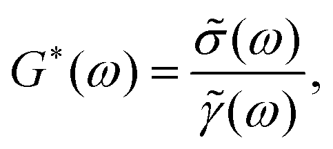

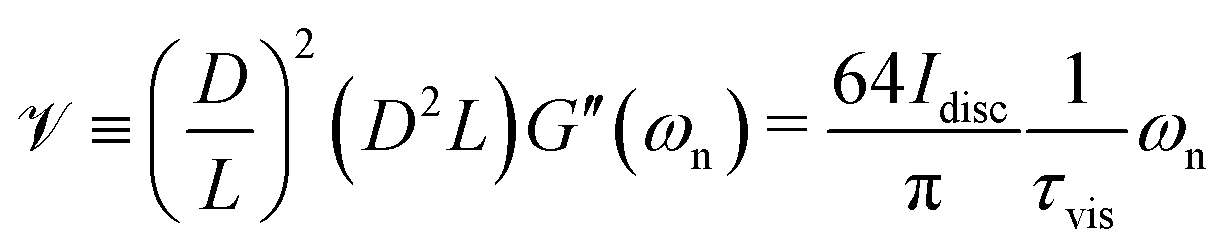
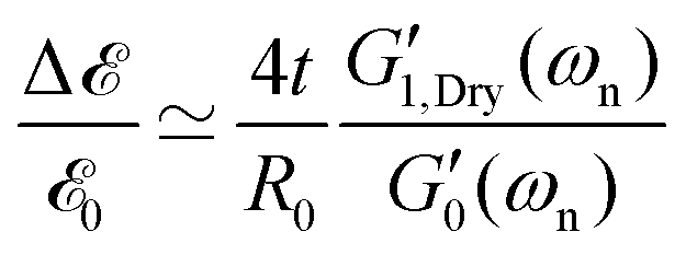

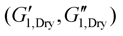 and
and 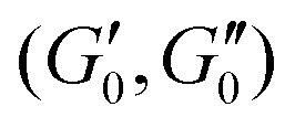 respectively. The suggested approximation of our analytical model and the observed trend in energy measures can be also understood with a simple physical argument based on the relative scales of viscoelastic energies involved. For an uncoated fiber the viscoelastic energy measures (per unit length) scale as the cross-sectional area multiplied by the respective viscoelastic moduli; i.e.
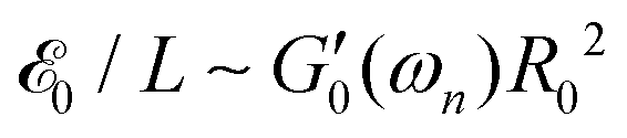 and
and  . Similarly, the incremental viscoelastic energies in the thin coating (per unit length) scale as
 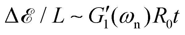 and
and 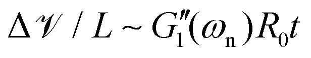 . Thus the normalized values of enhancements in viscoelastic energy measures scale as
 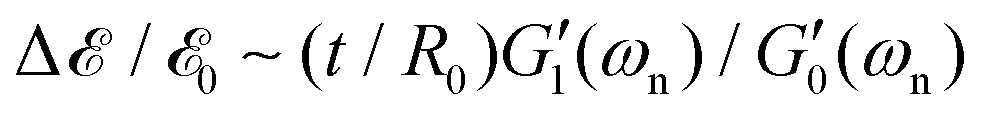 and
and 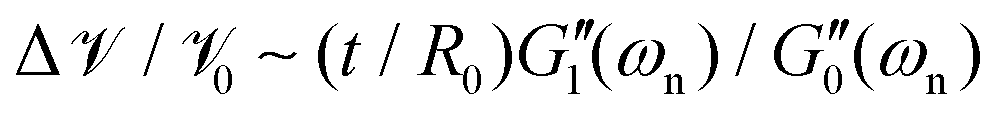 .
.
 of the uncoated fiber. Filled red and blue open triangles represent measures for stored elastic energy and viscoelastically dissipated energy respectively. Dashed lines show the corresponding predictions of the theoretical model as described by eqn (12a) and (12b). (c) The apparent increase in the torsional shear modulus
  (filled magenta circles) and the increment in the tensile elastic modulus ΔE/E0 (filled cyan squares) measured respectively by the torsional pendulum and tensile tests. Dashed lines show the corresponding predictions of the theoretical model as described by eqn (13a) and (13b).

 and
and  are the drying coefficients for the elastic storage modulus and the viscous loss modulus respectively. As shown in Fig. 6(b), these approximations successfully fit the measured data with drying coefficients ce = 1092 and cv = 557 used as fitting parameters. Thus, simple torsional pendulum measurements can readily measure the incremental changes in the viscoelastic properties of fibers coated with a thin film, as well as the systematic changes resulting from increasing the polymer concentration in the coating.
 (measured from the torsional pendulum test) where the data is normalized based on the tensile and shear moduli of the uncoated fiber, E0 and
  respectively.
 and E1 respectively) that increases the radius from R0 to R1. For such a fiber the apparent shear modulus, which can be measured in a torsional test, increases by
  while the apparent tensile modulus increases by ΔE = E1[(R1/R0)2 − 1]. For a thin coating where t = (R1 − R0) ≪ R0 we can approximate these analytic expressions at leading order as
  and ΔE/E1 ≃ (2t/R0)[E1/E0] suggesting that the torsional measurements are at least twice as sensitive to the coating properties of a thin coating when contrasted with tensile measurements. Fig. 6(c) shows a similar trend; for all of the tested coatings the torsional measurements are a factor of two more sensitive to the coating properties than the tensile tests. Knowing that both the shear and tensile moduli in the fully dried coating are larger than their corresponding values in the hydrated state (i.e.
 with ce ≫ 1) we provide an analytical approximation for the increase in the effective values of measured shear and tensile moduli:
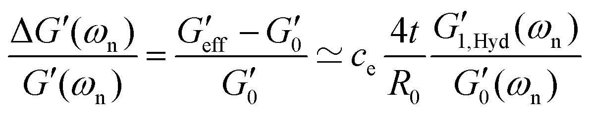
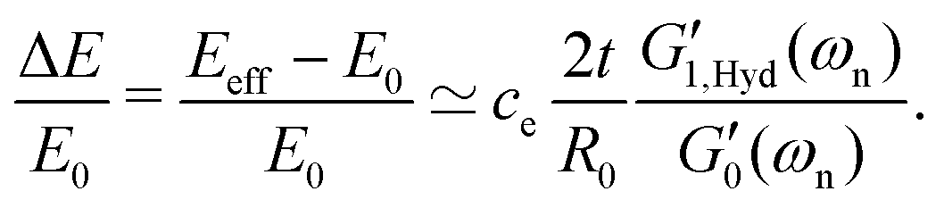
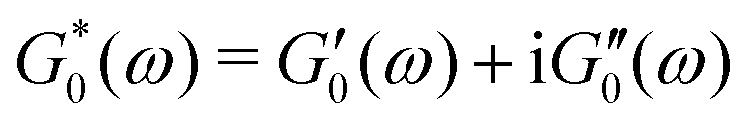 throughout its length L. We assume that a uniform coating with thickness t covers the core from R0 to R1 = R0 + t. The coating material is also characterized through its own complex viscoelastic modulus
 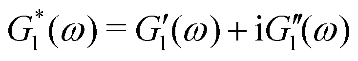 . As shown in Fig. 7, the optically measured profile of a typical fishing line fiber before and after the coating verifies the assumption of uniform coating thickness along the length of the fiber.

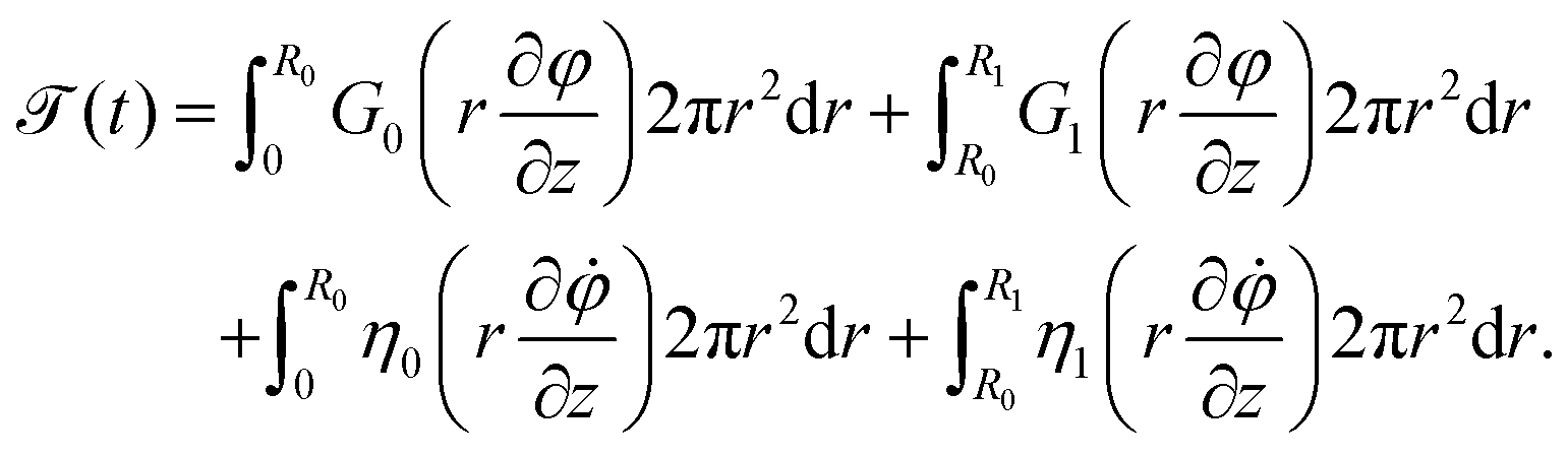
 ,
,  , and similarly the viscosity values are proportional to the loss moduli of each material at the resonant frequency
  ,
,  . We use separation of variables to describe the twist angle as a product of two separable spatial and temporal functions ϕ(z, t) = f(z)g(t). Consequently, we write the balance of torque in each cross-section as:
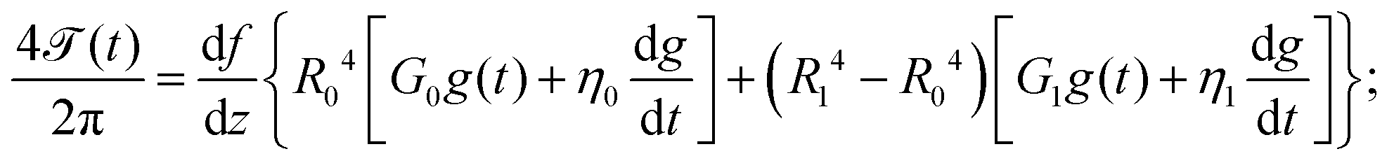


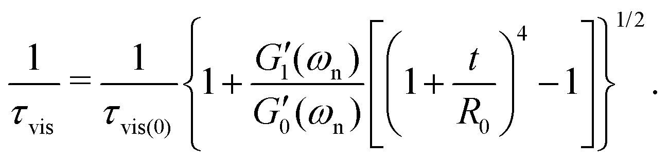
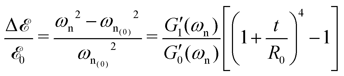
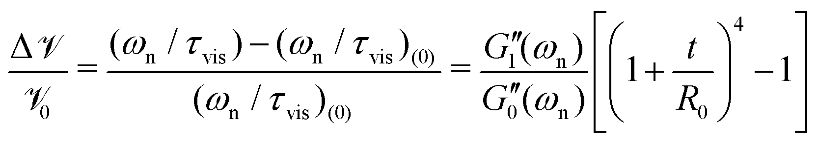
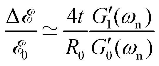
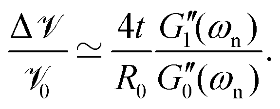
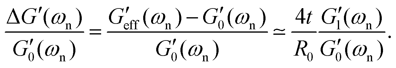
 and also by four times the geometrical ratio of coating thickness over core radius 4t/R0.
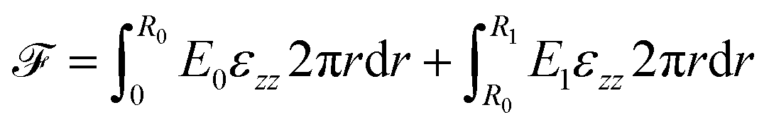
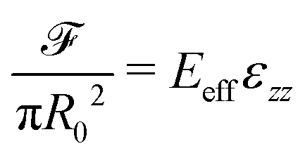
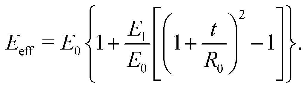
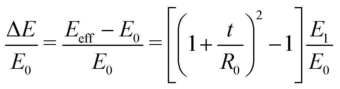
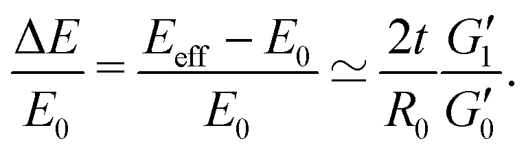
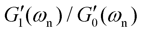 . However, the geometrical ratio 2t/R0 is reduced by a factor of two compared to the torsional analysis leading to eqn (21).