
Directly embedded Ni3S2/Co9S8@S-doped carbon nanofiber networks as a free-standing anode for lithium-ion batteries†
Zizhou
He
a,
Hui
Guo
ag,
Jed D.
LaCoste
a,
Ryan A.
Cook
a,
Blake
Hussey
a,
Xu
Zhang
c,
Daniel Dianchen
Gang
c,
Ji
Hao
d,
Liang
Chen
e,
Peter
Cooke
f,
Hui
Yan
b and
Ling
Fei
 *a
*a
aDepartment of Chemical Engineering, University of Louisiana at Lafayette, Lafayette, LA 70504, USA. E-mail: ling.fei@louisiana.edu
bDepartment of Chemistry, University of Louisiana at Lafayette, Lafayette, LA 70504, USA
cDepartment of Civil Engineering, University of Louisiana at Lafayette, Lafayette, LA 70504, USA
dNational Renewable Energy Laboratory, Materials Science Center, Golden, CO 80401, USA
eNew Jersey Institute to Technology, Newark, NJ 07102, USA
fCore University Research Resources Laboratory, New Mexico State University, Las Cruces, NM 88003, USA
gSchool of Chemical Engineering, Zhengzhou University, Zhengzhou 450001, P. R. China
First published on 14th October 2020
Abstract
Transition metal sulfides as electrode materials for lithium-ion batteries have attracted significant research attention due to their high theoretical capacity, excellent redox reversibility, and earth abundance. However, this material family still suffers from poor conductivity and experiences huge volume changes. Here, we demonstrate a facile and scalable electrospinning method to prepare Ni3S2 and Co9S8 nanoparticles embedded in sulfur doped carbon nanofiber networks as a free-standing anode material for lithium ion batteries. Similar to literature findings, the coupling of two different metal sulfides indeed synergistically promoted the electrochemical performance. Embedding them within individual carbon nanofibers not only enhances the intrinsic conductivity, but also provides a highly stable structure, which results in excellent battery performance. Furthermore, the individual carbon nanofibers intertwine with each other to form a free-standing 3D nanofiber network which acts as a freeway network for fast electron transfer and the pores between fibers allow easy penetration of the electrolyte, namely easy lithium ion access to active nanoparticles. When directly applied as the anode in lithium ion batteries, the free-standing nanofiber mat bypassed all slurry making steps and showed excellent cycling stability with a high specific capacity of 528 mA h g−1 after 200 cycles at a current density of 300 mA g−1. Good rate capability was also obtained. Additionally, the charge storage process analysis indicated that the pseudocapacitive behavior of the material is attributed to its good performance. This work introduces a facile strategy to simultaneously and in situ generate Co9S8 and Ni3S2 nanoparticles within a S-doped carbon fiber matrix via facile electrospinning followed by a one-step heating procedure. It is demonstrated that the free-standing transition bimetallic sulfide nanofibers prepared are very promising for light and small battery applications.
Introduction
High-performance lithium-ion batteries (LIBs) have attracted tremendous interest of researchers globally due to the fast growing market of portable electronic devices and electric vehicles.1–3 However, conventional graphite with a theoretical capacity of 372 mA h g−1 hinders the development of LIBs.3 Therefore, developing high capacity, long lifespan, lightweight, and low-cost anode materials is urgent to meet the demand. Much effort has been made in recent years on earth-abundant and low-cost anode materials to develop next-generation lithium ion batteries,4 wherein, transition metal sulfides have shown desirable properties such as high theoretical capacity, conversion mechanism, and high redox reversibility.5 Among them, nickel and cobalt sulfides are the two most studied materials. For instance, CoS2, NiS2, Ni3S2, and Co9S8 have all been intensively studied as anode electrodes for Li/Na ion batteries.6–10However, cobalt sulfide and nickel sulfide anode materials are still facing several challenges. Firstly, the poor electrical conductivity and sluggish ion transport kinetics of the materials result in insufficient capacity, low coulombic efficiency, and poor cycle life.11,12 Secondly, the conversion-reaction type materials are suffering from huge volume changes during the repeated lithiation and de-lithiation process. The pulverization of anode materials will lead to the continuous formation of a solid electrolyte interphase (SEI) layer, resulting in low coulombic efficiency and consumption of the electrolyte.13 Lastly, most of the prepared active metal sulfide materials are in a powder form which requires a tedious and time-consuming slurry making approach to make electrodes.14 The slurry-based electrodes not only tend to form undesired interfaces, uncontrollable microstructure, and limited surface area, but also increases the cost and weight of the electrode due to the involvement of extra binder, conductive materials, and current collector.14,15 Motivated by the above issues, to enhance the conductivity and performance, metal-based materials are usually combined with carbon materials or embedded in carbon matrices.16,17 Carbon matrices can effectively enhance the conductivity and prevent the agglomeration of ultra-fine nanoparticles, as well as release the stress of volume change induced by repeated charge and discharge processes.18,19 It has also been found that rationally combining and regulating cobalt sulfides with nickel sulfides is very promising for optimized performance in both energy storage and energy conversion applications.20–23 For instance, Du et al., prepared defect-enriched foam-like Co9S8/Ni3S2 nanowires via an in situ vulcanization method and achieved a low overpotential of 227 mV and −128 mV for the OER and HER, demonstrating an excellent bifunctional electrocatalyst.24 Wang and co-workers reported an in situ sulfurization strategy to synthesize Ni3S2 and Co9S8 nanoparticles embedded in nitrogen-doped porous carbon as a supercapacitor electrode with a superior specific capacitance of 1970.5 F g−1 at 0.5 A g−1, high rate capability and a high energy density of 77.1 W h kg−1 at 263.3 W kg−1.25 Zhu's group derived a Ni3S2/Co9S8/N-doped carbon composite from a Ni–Co-MOF precursor, and the composite material delivered a superior reversible capacity of 419.87 mA h g−1 at 0.1 A g−1 and 98.6% capacity retention after 100 charge/discharge cycles as well as outstanding rate capability as an anode material for sodium ion batteries.26 Moreover, due to the tedious traditional electrode preparation and weight of non-electrochemically active materials, it is highly desirable to develop free-standing anode materials to bypass the slurry coating procedure and significantly reduce the weight of batteries with no binder, extra conductive materials, and current collectors involved.14
Herein, we use a straight-forward, scalable, and low-cost electrospinning technique to embed Co9S8–Ni3S2 nanoparticles in S-doped carbon nanofiber networks as a free-standing anode material for LIBs. At the nanoscale the nanosized Co9S8/Ni3S2 nanoparticles and S-doped carbon nanofibers provide the following advantages: (i) the nanosized materials shorten the pathway of Li ion diffusion which further promotes the ion transfer rate and reaction kinetics; (ii) the coupling of Co9S8 and Ni3S2 nanoparticles can offer synergistic effects; (iii) the structure of nanoparticles embedded in the 1D carbon nanofiber provides excellent mechanical stability. Meanwhile, at the microscale (i) these nanofiber networks provide a stable 3D structure with high flexibility; (ii) numerous pores in the networks allow easy penetration of the electrolyte and quick access; (iii) the porous structure has enough space to alleviate the volume change. Benefitting from the above advantages our delicately designed Co9S8/Ni3S2@S-CNFs exhibited excellent cycling performance and remarkable rate capability. Specifically, the Co9S8/Ni3S2@S-CNFs maintained 528 mA h g−1 with 99.87% coulombic efficiency after 200 charge/discharge cycles at a current density of 300 mA g−1, and a high rate capability of 395.5 mA h g−1 at 1 A g−1. The facile, scalable and cost efficient synthesis approach provides a promising way for developing novel anode materials for LIBs.
Experimental section
Synthesis of Ni3S2/Co9S8@S-doped carbon nanofiber networks
N,N-Dimethylformamide (DMF, ACS grade, VWR), cobalt(II) acetate tetrahydrate (Co(CH3COO)2·4H2O, ACS Regent 98%, Sigma Aldrich), nickel(II) acetate tetrahydrate (Ni(OCOCH3)2·4H2O, 98%, Sigma Aldrich), sulfur (S, ≥99.5%, powder −100 mesh, sublimated, Alfa Aesar), and polyacrylonitrile (PAN, average MW 150![[thin space (1/6-em)]](https://www.rsc.org/images/entities/char_2009.gif) 000, Sigma Aldrich) were used directly without further purification.
000, Sigma Aldrich) were used directly without further purification.
In a typical procedure, 0.5 g of PAN was dissolved in 5 g DMF and heated at 80 °C overnight to form a homogeneously transparent solution. Then 2.3 mmol of metal acetates Ni(OCOCH3)2·4H2O and (CH3COO)2Co·4H2O (the molar ratio of Ni:Co was 1:1) were added into the obtained 10 wt% PAN with vigorous stirring for 1 h. Then 0.2 g S powder was added into the solution. The mixture was well dispersed through ultra-sonication and vigorous stirring. The obtained solution was transferred into a 5 mL plastic syringe with a 20 gauge, 2 inch, point style 3 needle (Hamilton, USA). The electrospinning was carried out by using a Pump 11 Elite Infusion Dual Syringe pump (Harvard apparatus, USA). The feeding rate of the pump was set as 15 μL min−1. A piece of aluminum foil was used as the nanofiber collector. The distance between the collector and the needle was fixed at 15 cm, and the working voltage between the needle and collector at 17.5 kV.
The as-prepared Ni–Co–S/(PAN)NF precursor was peeled off from the aluminum collector for thermal treatment. The precursor was heat treated in a tube furnace in a nitrogen atmosphere for 1 h at 700 °C with a ramp rate of 5 °C min−1. After cooling down to room temperature naturally under a nitrogen flow, the Ni3S2/Co9S8@S-doped carbon nanofiber networks were obtained; Ni3S2@S-doped carbon nanofiber networks and Co9S8@S-doped carbon nanofiber networks were also synthesized under the same conditions without adding Co/Ni(Ac)2 for comparison.
Characterization
X-ray diffraction (Rigaku D/Max2500 with CuKα radiation) was employed with a scanning rate of 3° min−1 in a 2-theta range of 10°–80°. A Micromeritics ASAP 2020 was used to determine the BET surface area and pore size distribution. The X-ray photoelectron spectroscopy (XPS) measurements were performed with an Al K alpha X-ray source. The morphological information was obtained using a Thermo Scientific™ Apreo scanning electron microscope (SEM). Transmission electron microscopy (TEM) and high resolution TEM (HRTEM) were carried out by using a Tecnai G2 F20. Thermogravimetric analysis (TGA) was performed with a TGA-1000 from room temperature to 800 °C with a ramp rate of 10 °C min−1.Half-cell battery preparation and electrochemical measurement
The obtained free-standing Ni3S2/Co9S8@S-CNFs were cut into 0.9–1.2 mg fiber mats and directly used as an electrode for LIBs. The electrochemical performance of the electrodes was investigated by using CR2032 coin cells with lithium metal foil as the counter and reference electrode. 1 M LiPF6 in a mixture of ethylene carbonate/dimethyl carbonate/diethyl carbonate (EC/DMC/DEC, 1:1:1 in volume) solution was used as the electrolyte. A Celgard 2400 film was used as the separator. The coin cells were assembled in an argon-filled glovebox with oxygen and water content levels lower than 1 ppm. Cyclic voltammetry was carried out using a STAT III electrochemical workstation (Princeton Applied Research, USA) at a scan rate of 0.2 mV min−1 in the voltage window of 0.01–3 V versus lithium (vs. Li+/Li). The galvanostatic charge/discharge measurements were performed using a Landt battery testing system in the voltage window of 0.05–3 V (vs. Li+/Li). The electrochemical impedance spectroscopy (EIS) measurements were conducted after cycling 200 times at room temperature in a range of 100000 Hz to 0.1 Hz.
Results and discussion
The synthetic procedure of Ni3S2/Co9S8@S-doped carbon nanofibers is summarized in Fig. 1; nickel and cobalt acetate in a desired ratio are dissolved in PAN-DMF solution and then sulfur particles are dispersed in the solution. Fresh Ni/Co(AC)2 nanofiber mats were prepared via electrospinning.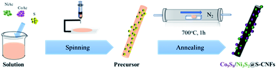 | ||
| Fig. 1 Schematic illustration of the Ni3S2/Co9S8@S-CNF synthetic procedures. | ||
The as-spun mats were then subjected to a thermal treatment in N2. During this process, the metal acetates and sulfur react with each other to form metal sulfides, while the PAN polymer backbones simultaneously convert to carbon nanofibers. To understand the phase structures and crystallinity of the obtained samples, XRD was first carried out. As shown in Fig. 2a, the strong and sharp diffraction peaks at 2 theta values of, 21.8°, 31.1°, 37.8°, 49.7° and 55.2° correspond to the planes of (1 0 1), (1 1 0), (0 0 3), (1 1 3) and (1 2 2) of the hexagonal Ni3S2 phase respectively (JCPDS no. 44-1418). The Bragg peaks located at 29.9°, 47.4° and 52.0° could be ascribed to the (3 1 1), (5 1 1) and (4 4 0) planes of the Co9S8 phase (JCPDS no. 19-0364). All the peaks in the XRD patterns can be indexed to the two metal sulfides, which indicates the coexistence of both Co9S8 and Ni3S2 in the sample. For the single precursor samples, Ni3S2 and Co9S8 were synthesized correspondingly.
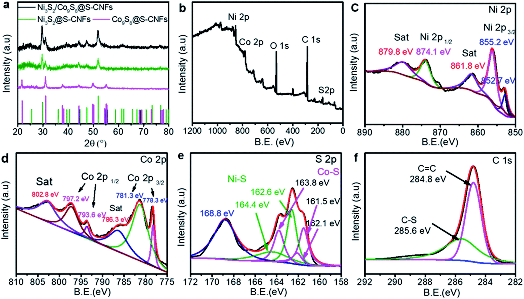 | ||
| Fig. 2 (a) XRD patterns of metal sulfides@S-CNFs, (b) XPS survey spectra, and (c–f) high-resolution XPS spectra of Ni 2p, Co 2p, S 2p and C 1s of the as-obtained Ni3S2/Co9S8@S-CNF composite. | ||
To further understand the surface elements' chemical states and chemical compositions of the Ni3S2/Co9S8@S-CNF sample, X-ray photoelectron spectroscopy (XPS) was conducted. The full XPS survey spectrum of the Ni3S2/Co9S8@S-CNF sample is shown in Fig. 2b. The peaks at 856.1 and 797.2 eV correspond to Ni 2p and Co 2p, respectively, while the peaks at 284.8 and 162.4 eV are attributed to the C 1s and S 2p, confirming the presence of Ni, Co, S and C elements. The high-resolution spectrum of Ni 2p is shown in Fig. 2b. The two satellite peaks at 861.8 and 879.8 eV are shakeup type peaks of Ni.27 The two peaks located at 874.1 and 855.2 eV correspond to the Ni 2p3/2 and Ni 2p1/2 spin–orbit peaks.28 The peak at 852.7 eV is the characteristic peak of Ni3S2.29 The Co 2p spectrum is shown in Fig. 2c, and the two shakeup satellite peaks at 786.3 and 802.8 eV can be attributed to Co3+.30
The two spin–orbit doublets with peak locations shown at 778.3 and 781.3 eV can be assigned to Co 2p3/2, while the two peaks at 793.6 and 797.2 eV can be ascribed to Co 2p1/2, respectively. The wide peaks of Co 2p3/2 and Co 2p1/2 indicated the co-existence of Co2+/Co3+ species and the formation of Co9S8.31Fig. 2d shows the S 2p spectrum, and the spectrum can be divided into six peaks. The presence of a peak at 163.8 is ascribed to S 2p1/2, and at 161.5 and 162.1 eV corresponds to S 2p3/2 of Co–S.22,32,33 Meanwhile, the other two peaks at 164.4 and 162.6 eV corresponded to S 2p1/2 and S 2p3/2 of Ni–S.22 The S 2p peak at around 168.8 eV can be indexed to the surface oxidation. The C 1s spectrum is shown in Fig. 2f, and the peak at 285.6 eV can be ascribed to the C–S bond, indicating that excess sulfur was doped into the carbon nanofiber networks. The cooperation of metal sulfides with the S-doped PAN composite can effectively improve the energy density of the electrode.34,35 The XPS results are in good agreement with the XRD results above, further affirming the co-existence of Co9S8 and Ni3S2.
The morphology and microstructure of Ni3S2/Co9S8@S-CNFs were observed by FESEM and are shown in Fig. 3a and b. The images show that the carbon nanofibers are closely intertwined with each other and form an interconnected 3D network. There are also lots of void space among the fiber mats, which could allow the electrolyte to easily access the metal sulfide nanoparticles as well as release the stress of volume change of the electrode. Furthermore, the ultrafine metal sulfide nanoparticles were embedded on the surface of the carbon nanofibers without obvious agglomeration, which indicates the active sites present along with the carbon nanofiber network, different from traditional powdered anode materials due to no binder and extra conductive materials involved. The nanosized carbon fiber and metal sulfide nanoparticles exhibit a short Li+ ion pathway for fast Li+ ion transfer.
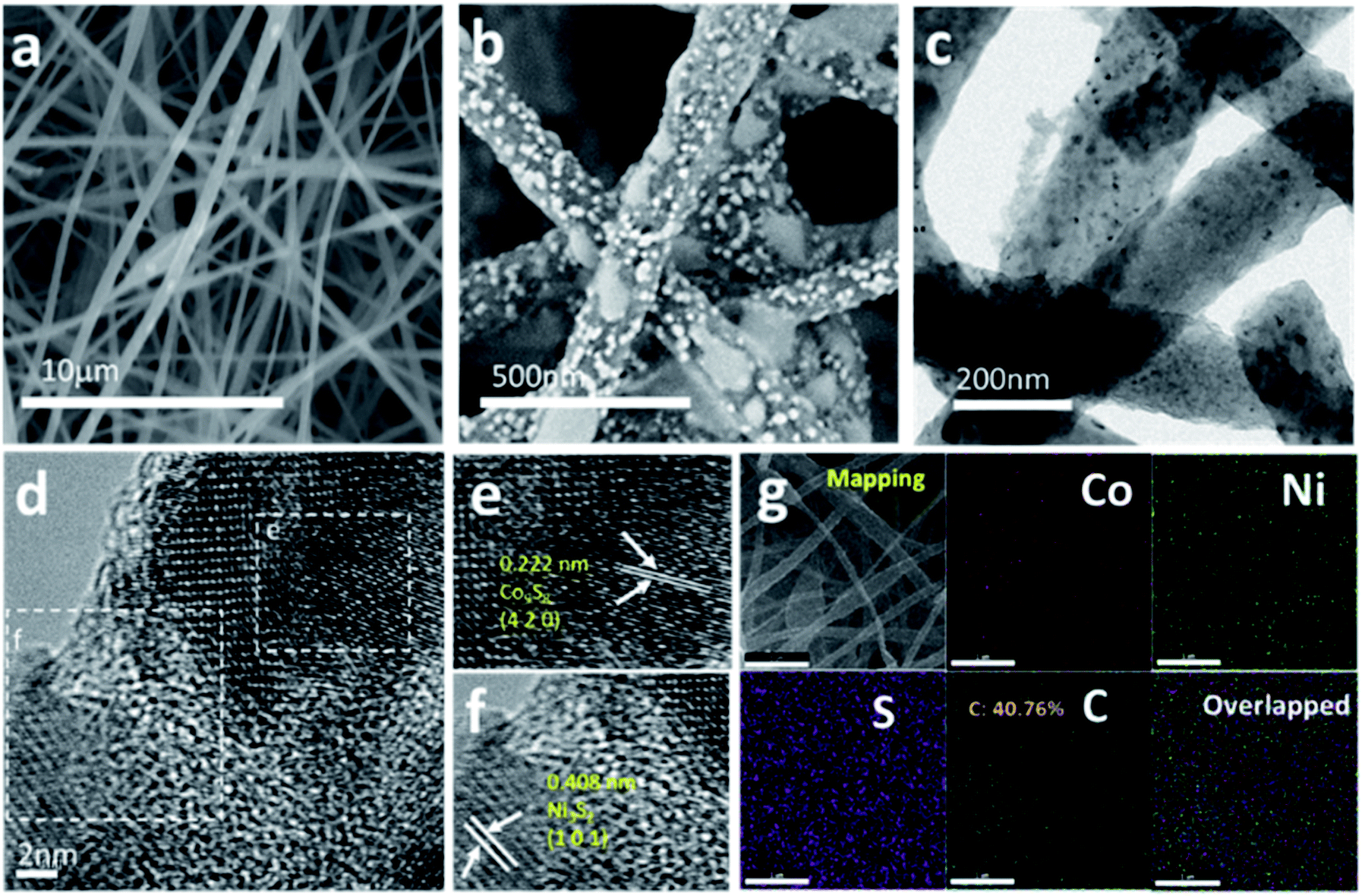 | ||
| Fig. 3 (a) Low-magnification SEM image, (b) high-magnification SEM image, (c) TEM images of the as-prepared the Ni3S2/Co9S8@S-CNF composite, (d–f) high-resolution TEM (HRTEM) image of the as-prepared Ni3S2/Co9S8@S-CNF composite, and (g) EDX mapping images of the Ni3S2/Co9S8@S-CNF composite at a scale of 1 μm. | ||
To further investigate the structure and morphology of Ni3S2/Co9S8@S-CNFs, TEM and HRTEM analyses were carried out. As shown in Fig. 3c, the diameter of the carbon nanofibers is around 150 nm. Nanoparticles are distributed on the carbon nanofibers without agglomeration, which can maximize the exposure of the active sites while giving enough space to release the stress of volume change. The HRTEM images are shown in Fig. 3d–f. From Fig. 3d, it can be seen that the particles are not interconnected with each other and two different areas were selected for further investigation. As shown in Fig. 3e, the lattice fringe with a spacing of 0.222 nm corresponds to the (4 2 0) lattice plane of Co9S8. Meanwhile, the lattice fringe spacing of 0.408 nm assigned to the (1 0 1) crystal plane of Ni3S2 is shown in Fig. 3f. These results further support the previous conclusions. EDX elemental mapping was used to explore the metal sulfide distribution and is shown in Fig. 3g. From the EDX maps, Ni, Co, S and C are observed to be homogeneously distributed on the selected area, and the Ni and Co ratio is 1:1.02. Moreover, the composition of the as-prepared samples was determined by TGA. Fig. S1† shows that the calculated weight percentage of carbon in Ni3S2/Co9S8@S-CNFs, Ni3S2@S-CNFs, and Co9S8@S-CNFs is 58.5%, 60.5%, and 49.3% respectively. Nitrogen adsorption and desorption measurement was conducted to investigate the sample surface area and pore size distribution. Ni3S2/Co9S8@S-CNFs, Ni3S2@S-CNFs, and Co9S8@S-CNFs show a BET specific surface area of 371.9, 306.6 and 283.0 m2 g−1 (Fig. S2a†), respectively. The pore size of the samples (Fig. S2b†) is around 2–4.3 nm. The large specific surface area and mesoporous structure can accelerate ion transfer and help to buffer the volume change in the discharge–charge process, thereby further enhancing the electrochemical performance.
Cyclic voltammetry (CV) measurements were carried out to evaluate the electrochemical performance of the electrode during lithiation/de-lithiation in a window of 0.01 to 3 V at a scan rate of 0.2 mV s−1. Fig. 4a shows the CV curves of Ni3S2/Co9S8@S-CNFs. In the first cycle the cathodic peak at 0.77 V can be ascribed to the formation of a solid electrolyte interface (SEI) layer. The cathodic peak at around 1.1 V is due to the insertion of Li+ and the formation of Ni and Co (4Li+ + 4e− + Ni3S2 ↔ 3Ni + 2Li2S, 16Li+ + 16e− + Co9S8 ↔ 9Co + 8Li2S).9,36 The anodic peak located at 2.05 V indicates the formation of metal sulfides.37–39 The CVs of single metal sulfides Ni3S2@CNFs and Co9S8@CNFs are compared and shown in Fig. 4b and c, and the CV curves of the two single metal sulfides also reflect a good overlap between the subsequent cycles. The overlapping of the CV curves between cycles reveals the good electrochemical reversibility of the metal sulfide electrodes during the redox process. The good redox reversibility can be attributed to the carbon nanofibers serving as a buffer during the lithiation and de-lithiation processes and releasing the stress of volume expansion and the shrinkage of the embedded metal sulfide nanoparticles. The unique architecture guarantees the excellent cycling performance. Moreover, the Ni3S2/Co9S8@S-CNF peaks overlap the best in comparison with those of the single metal electrodes: Ni3S2@S-CNFs and Co9S8@S-CNFs. These results suggest the synergistic effects between these two metal sulfide species.
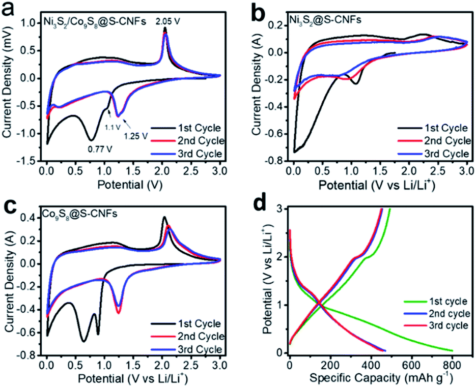 | ||
| Fig. 4 (a–c) CV profiles of the Ni3S2/Co9S8@S-CNFs, Ni3S2@S-CNFs, and Co9S8@S-CNFs at a scan rate of 0.2 mV s−1 in a potential window from 0.01 to 3 V, and (d) galvanostatic charge–discharge profiles of the Ni3S2/Co9S8@S-CNF anode at 300 mA g−1. | ||
Fig. 4d shows the galvanostatic discharge/charge profiles of Ni3S2/Co9S8@CNFs at a current density of 300 mA g−1. The profile shows a high initial discharge capacity of 799 mA h g−1 with a discharge plateau at ∼1.1 V resulting from the formation of Ni and Co; after the first cycle, the plateau shifts to a slightly higher voltage, in good agreement with the cathodic peak (∼1.2V) position shifting trend in the CV scan. The first charge capacity is 492 mA h g−1 with a charge plateau at ∼2 V due to the de-lithiation. It gives an initial coulombic efficiency (CE) of 61.6%. The low initial coulombic efficiency is caused by the irreversible consumption of lithium ions as well as the formation of solid electrolyte interphase (SEI) layers. Sequentially, the CE of the second cycle and third cycle jumped to 96.8% and 98.7%. The second and third cycles show negligible capacity loss, indicating the good reversibility of the composite anode materials. The above results are also in good agreement with the CV results.
Cycling performance is one of the most important parameters for electrode materials. The as-synthesized metal sulfides in fiber mats were cut into small pieces and directly applied as free-standing anodes in coin cells for performance evaluation. The samples were tested in the voltage window of 0.05 to 3 V vs. Li+/Li at a current density of 300 mA g−1 for 200 cycles. It is worth mentioning that the current density and specific capacity are based on the mass of the whole electrode. As shown in Fig. 5a, the Ni3S2/Co9S8@S-CNFs exhibited the highest initial capacity as well as the best cycling performance compared with the individual metal sulfides, and this is due to the synergistic effect between the two metal sulfides. An irreversible capacity loss is observed after the first cycle, for the Ni3S2/Co9S8@S-CNFs which can be generally ascribed to the formation of the SEI film and electrolyte decomposition. This phenomenon agrees well with the CV result that the cathodic peaks are present in the first cycle while absent in sequential cycles. After the first cycle there is a slight capacity increase of the electrode which can be ascribed to the gradual activation of the electrode materials; this phenomenon was also observed for transition metal anode materials in previous studies.5,40–42 Meanwhile, its coulombic efficiency increases to more than 99% after the fourth cycle and stays at this number for the remaining cycles. After 200 cycles, the Ni3S2/Co9S8@S-CNFs can still maintain 527.8 mA h g−1, nearly 100% coulombic efficiency and zero capacity loss demonstrating good long-term cycling stability. Co9S8@S-CNFs and Ni3S2@S-CNFs achieved an initial capacity of 748.5 and 735.6 mA h g−1; after 200 cycles they retain a specific capacity of 490.3 and 244.6 mA h g−1. The capacity retention is 100% and 66% of the second discharge capacity. The composite electrode exhibited higher initial capacity, specific capacity, and better cycling retention than Ni3S2@S-CNFs and Co9S8@S-CNFs, and this phenomenon can be ascribed to the synergistic effect of Ni and Co sulfides.26,43 To further investigate the synergistic effect, we studied the three composites at a higher cycling current density of 1 A g−1. The results are shown in Fig. 5b. It can be seen that no obvious difference was observed in the initial 50 cycles for Ni3S2/Co9S8@S-CNFs and Co9S8@S-CNFs, similar to what we observed in the cycle performance at a current density of 300 mA g−1. However, after the initial 50 cycles at high current density, Ni3S2/Co9S8@S-CNFs still maintain the highest specific capacity among the three electrodes, and no obvious capacity fading was observed in the 300 cycles. While Co9S8@S-CNFs show a decay in the range of 50 to 150 cycles, showing a capacity of 262.3 mA h g−1 at the 300th cycle lower than the specific capacity (442.5 mA h g−1) of Ni3S2/Co9S8@S-CNFs and confirming the good stability and synergistic effect of the bimetallic composites. To investigate the structural stability of the Ni3S2/Co9S8@S-CNF anode, the SEM image of the anode cycled for 200 cycles at 1 A g−1 was obtained. As can be seen in Fig. S3,† the Ni3S2/Co9S8@SCNF electrode still maintained the fiber morphology with a continuously interconnected 3D network, indicating the remarkable structural stability of the materials. The cycling stability of this type of electrode is due to the well-designed structure of the electrode. The robust carbon nanofiber networks can effectively buffer the stress of volume change during the repeated charge and discharge processes, preventing the electrode pulverization.
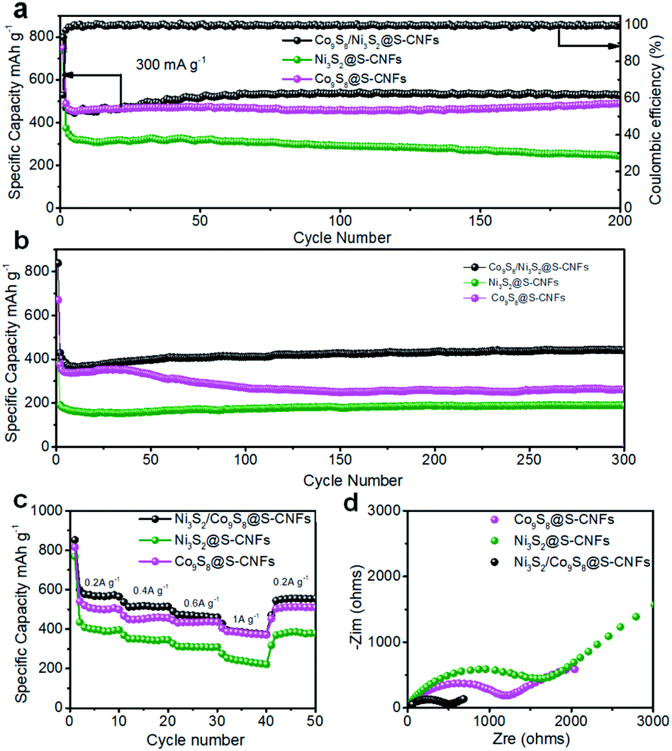 | ||
| Fig. 5 (a) Cycling performance and coulombic efficiency of the Ni3S2/Co9S8@S-CNFs, Ni3S2@S-CNFs and Co9S8@S-CNFs at (a) 300 mA g−1 for 200 cycles, and (b) 1 A g−1 for 300 cycles. (c) Rate performance of the Ni3S2/Co9S8@S-CNF, Ni3S2@S-CNF and Co9S8@S-CNF anodes at different current densities and (d) electrochemical impedance spectra (EIS) of Ni3S2/Co9S8@S-CNFs, Ni3S2@S-CNFs and Co9S8@S-CNFs tested at open circuit potential. | ||
Rate capability, another important parameter, indicates the electrode capability of fast Li-ion transfer and storage. As shown in Fig. 5c, the Ni3S2 and Co9S8 composite electrode delivers a 10th cycle capacity of 564.6 mA h g−1 at 0.2 A g−1, 514.3 mA h g−1 at 0.4 A g−1, 459.9 mA h g−1 at 0.6 A g−1, and 373.4 mA h g−1 at 1 A g−1. When the current density went back to 0.2 A g−1, the capacity was almost fully recovered and a specific capacity of 555.6 mA h g−1 was maintained (only 9 mA h g−1 loss over 50 cycles), showing good rate capacity retention. The other single sulfide electrodes show a similar tendency except for a slightly lower specific capacity, which indicates that these types of free-standing electrodes have high structural stability and fast ion/electron transfer. The individual fiber connected 3D network structure provides a lot of micrometer pores in the fiber mats which enables the fast penetration of the electrolyte, namely, easy access of lithium ions to active material sites. In addition, the interconnected 1D carbon nanofiber backbones act as freeways for electron transfer as well as buffer the volume change during lithiation and de-lithiation.
To further study the effects of concurrent growth of the two metal species, electrochemical impedance spectroscopy (EIS) was conducted. As Fig. 5d shows, all the electrodes exhibit a single semicircle in the high frequency region, and a slope line in the low frequency region. The semicircle in the high frequency region is considered to be related to the charge transfer resistance, and the slope line in the low frequency region corresponds to the lithium ion diffusion in the solid phase44–46 The Ni3S2/Co9S8@S-CNFs present the smallest semicircles compared with the Ni3S2@S-CNF and Co9S8@S-CNF electrodes, indicating that the composite electrode had a smaller charge resistance as well as better charge transfer kinetics than single metal sulfide electrodes, and this further affirms the synergistic effects of the two metal sulfides.5,37 The tail in the low-frequency region corresponds to the Li diffusion process, and the lithium ion diffusion coefficient was compared according to the eqn (S1)† by comparing the σ, which is the slope of the line Z′–ω−1/2 (Fig. S4†). The lithium ion diffusion coefficient is inversely proportional to σ.47 As shown in Fig. S4,† the Ni3S2/Co9S8@S-CNFs have the least σ and this indicates a larger lithium ion diffusion coefficient, which is consistent with the cycling performance results. It is also worth noting that the diffusion coefficient is an important parameter but not necessarily the most decisive one on performance. Yin et al. found that the porous structure, N/S doped carbon, good structural stability, and excellent electronic conductivity are more critical than the Li diffusion coefficient for superior rate and long cycling performance.47 In our case, the specific surface area of Ni3S2/Co9S8@S-CNFs is highest than the other two. The more porous structure together with the large lithium diffusion coefficient is likely the key to their excellent performance. Moreover, it has also been concluded by Fang et al. that compared to monometallic sulfides, two bimetallic sulfides can enhance the ion diffusion and conductivity due to the following two reasons: (1) phase boundaries tend to limit the growth of crystals and create crystal defects and active sites for fast ion diffusion, and (2) different redox potentials and out-of-step reactions of the two metal sulfides could alleviate the stress during cycling which is helpful for ion diffusion.48 Therefore, the bimetallic sulfides outperform the two monometallic sulfides.
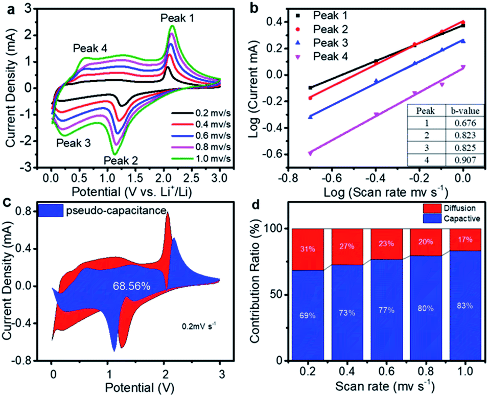
Significant pseudocapacitive behavior of transition metal chalcogenides has been demonstrated according to previous studies.5,49,50 Herein, to understand the lithium storage mechanism, the CV measurement of the Ni3S2/Co9S8@S-CNF electrode at various scan rates from 0.2 to 1 mV s−1 was recorded to study its electrochemical kinetics.51 As shown in Fig. 6a, the peak current density increases with the increase of the scan rate and the CV curve shapes remain the same. The lithium storage mechanism can be evaluated by the relationship between the peak current (i) and scan rate (ν) from the CV results, based on eqn (1)52
| i = aνb | (1) |
| log(i) = blog(ν) + log(a) | (2) |
| i(v) = k1v + k2v1/2 | (3) |
 | ||
| Fig. 6 (a) CV curves of the cell at different scan rates after ten cycles, (b) the fitted lines and ln(peak current) vs. ln(scan rate) plots in different oxidation and reduction states, (c) the pseudo-capacitance contribution (0.2 mV s−1) is 69% and shown by the blue region, and (d) the pseudo-capacitance contribution at different scan rates. | ||
As Fig. 6d shows, the contribution of the pseudo-capacitance increased with an increase in the scan rate, while the diffusion contribution decreased. At a scan rate of 0.2, 0.4, 0.6, 0.8, and 1 mV s−1 the contribution of the pseudo-capacitance is about 69%, 73%, 77%, 80%, and 83%, respectively. This behavior indicates that the pseudo-capacitance is dominant at high scan rates. This is because of the well-designed structure providing a lot of active sites and short Li+ ion diffusion pathways, all contributing to high capacity and high-rate performance.5 It's also worth mentioning that the decrease of the diffusion contribution is due to the limited diffusion kinetics and increased ohmic resistance with the increasing scan rate.56
Conclusions
In summary, we have successfully embedded Ni3S2 and Co9S8 nanoparticles in S-doped carbon nanofiber networks as an anode electrode for high performance LIBs. The composite materials show improved electrochemical performance with excellent cycling performance and rate capability. The excellent performance should be ascribed to the well-designed structure that is able to alleviate the volume change stress, enhance the conductivity, and promote the reaction kinetics. Our results show that the electrode shows a good performance with a high 799 mA h g−1 initial discharge capacity and after 200 cycles it stabilized at 528 mA h g−1 with 99.87% coulombic efficiency at a current density of 300 mA g−1. Furthermore, a good rate capability of 373.4 mA h g−1 at 1 A g−1 is achieved. We believe our work provides a possible method for developing novel transition metal sulfide anode materials for small and light LIBs.Conflicts of interest
There are no conflicts to declare.Acknowledgements
We acknowledge the financial support from NASA EPSCoR/Louisiana Board of Regents (Sponsor ID: LEQSF-EPS (2020)-RAP-31). Dr Fei acknowledges Chevron Corporation for providing her with Chevron Endowed Professorship in Chemical Engineering at UL Lafayette. Ryan A. Cook acknowledges the fund support from UL Lafayette College of Engineering Research Apprentice program and the University Undergraduate Research Mini-Grant program.Notes and references
- S. Goriparti, E. Miele, F. De Angelis, E. Di Fabrizio, R. Proietti Zaccaria and C. Capiglia, J. Power Sources, 2014, 257, 421–443 CrossRef CAS.
- J. B. Goodenough and K. S. Park, J. Am. Chem. Soc., 2013, 135, 1167–1176 CrossRef CAS.
- M. Armand and J. M. Tarascon, Nature, 2008, 451, 652–657 CrossRef CAS.
- P. Poizot, S. Laruelle, S. Grugeon, L. Dupont and J. M. Tarascon, Nature, 2000, 407, 496–499 CrossRef CAS.
- T. Yang, Y. Liu, D. Yang, B. Deng, Z. Huang, C. D. Ling, H. Liu, G. Wang, Z. Guo and R. Zheng, Energy Storage Mater., 2019, 17, 374–384 CrossRef.
- J. Zhang, L. Yu and X. W. D. Lou, Nano Res., 2017, 10, 4298–4304 CrossRef CAS.
- J. Li, J. Li, Z. Ding, X. Zhang, Y. Li, T. Lu, Y. Yao, W. Mai and L. Pan, Chem. Eng. J., 2019, 378, 122108 CrossRef CAS.
- S. Ni, X. Yang and T. Li, Mater. Chem. Phys., 2012, 132, 1103–1107 CrossRef CAS.
- Y. Zhou, D. Yan, H. Xu, S. Liu, J. Yang and Y. Qian, Nanoscale, 2015, 7, 3520–3525 RSC.
- J. Li, J. Li, D. Yan, S. Hou, X. Xu, T. Lu, Y. Yao, W. Mai and L. Pan, J. Mater. Chem. A, 2018, 6, 6595–6605 RSC.
- Q. Zhou, L. Liu, Z. Huang, L. Yi, X. Wang and G. Cao, J. Mater. Chem. A, 2016, 4, 5505–5516 RSC.
- X. Y. Yu, H. Hu, Y. Wang, H. Chen and X. W. Lou, Angew. Chem., Int. Ed. Engl., 2015, 54, 7395–7398 CrossRef CAS.
- Y. Tan, M. Liang, P. Lou, Z. Cui, X. Guo, W. Sun and X. Yu, ACS Appl. Mater. Interfaces, 2016, 8, 14488–14493 CrossRef CAS.
- L. Fei, B. P. Williams, S. H. Yoo, J. M. Carlin and Y. L. Joo, Chem. Commun., 2016, 52, 1501–1504 RSC.
- T. Y. Ma, S. Dai and S. Z. Qiao, Mater. Today, 2016, 19, 265–273 CrossRef CAS.
- X. Zhang, R. Zhao, Q. Wu, W. Li, C. Shen, L. Ni, H. Yan, G. Diao and M. Chen, ACS Nano, 2017, 11, 8429–8436 CrossRef CAS.
- W. Li, R. Zhao, K. Zhou, C. Shen, X. Zhang, H. Wu, L. Ni, H. Yan, G. Diao and M. Chen, J. Mater. Chem. A, 2019, 7, 8443–8450 RSC.
- J. Xia, L. Liu, S. Jamil, J. Xie, H. Yan, Y. Yuan, Y. Zhang, S. Nie, J. Pan, X. Wang and G. Cao, Energy Storage Mater., 2019, 17, 1–11 CrossRef.
- N. Zhang, S. Gan, T. Wu, W. Ma, D. Han and L. Niu, ACS Appl. Mater. Interfaces, 2015, 7, 12193–12202 CrossRef CAS.
- J. Xie, X. Li, H. Lai, Z. Zhao, J. Li, W. Zhang, W. Xie, Y. Liu and W. Mai, Angew. Chem., Int. Ed. Engl., 2019, 58, 14740–14747 CrossRef CAS.
- D. Ghosh and C. K. Das, ACS Appl. Mater. Interfaces, 2015, 7, 1122–1131 CrossRef CAS.
- Y. Yang, H. Yao, Z. Yu, S. M. Islam, H. He, M. Yuan, Y. Yue, K. Xu, W. Hao, G. Sun, H. Li, S. Ma, P. Zapol and M. G. Kanatzidis, J. Am. Chem. Soc., 2019, 141, 10417–10430 CrossRef CAS.
- S. Zhuo, Y. Shi, L. Liu, R. Li, L. Shi, D. H. Anjum, Y. Han and P. Wang, Nat. Commun., 2018, 9, 3132 CrossRef.
- F. Du, L. Shi, Y. Zhang, T. Li, J. Wang, G. Wen, A. Alsaedi, T. Hayat, Y. Zhou and Z. Zou, Appl. Catal., B, 2019, 253, 246–252 CrossRef CAS.
- S. Wang, Z. Xiao, S. Zhai, H. Wang, W. Cai, L. Qin, J. Huang, D. Zhao, Z. Li and Q. An, J. Mater. Chem. A, 2019, 7, 17345–17356 RSC.
- X. Liu, F. Zou, K. Liu, Z. Qiang, C. J. Taubert, P. Ustriyana, B. D. Vogt and Y. Zhu, J. Mater. Chem. A, 2017, 5, 11781–11787 RSC.
- N. Cheng, Q. Liu, A. M. Asiri, W. Xing and X. Sun, J. Mater. Chem. A, 2015, 3, 23207–23212 RSC.
- X. Zhong, L. Zhang, J. Tang, J. Chai, J. Xu, L. Cao, M. Yang, M. Yang, W. Kong, S. Wang, H. Cheng, Z. Lu, C. Cheng, B. Xu and H. Pan, J. Mater. Chem. A, 2017, 5, 17954–17962 RSC.
- W. Zhou, X.-J. Wu, X. Cao, X. Huang, C. Tan, J. Tian, H. Liu, J. Wang and H. Zhang, Energy Environ. Sci., 2013, 6, 2921–2924 RSC.
- S. Zhang, D. Li, S. Chen, X. Yang, X. Zhao, Q. Zhao, S. Komarneni and D. Yang, J. Mater. Chem. A, 2017, 5, 12453–12461 RSC.
- X. Cao, X. Zheng, J. Tian, C. Jin, K. Ke and R. Yang, Electrochim. Acta, 2016, 191, 776–783 CrossRef CAS.
- H. Zhu, J. Zhang, R. Yanzhang, M. Du, Q. Wang, G. Gao, J. Wu, G. Wu, M. Zhang, B. Liu, J. Yao and X. Zhang, Adv. Mater., 2015, 27, 4752–4759 CrossRef CAS.
- S. Dou, L. Tao, J. Huo, S. Wang and L. Dai, Energy Environ. Sci., 2016, 9, 1320–1326 RSC.
- Z. Wang, Y. Dong, H. Li, Z. Zhao, H. B. Wu, C. Hao, S. Liu, J. Qiu and X. W. Lou, Nat. Commun., 2014, 5, 5002 CrossRef CAS.
- A. K. Haridas, J. Heo, Y. Liu, H. J. Ahn, X. Zhao, Z. Deng, M. Agostini, A. Matic, K. K. Cho and J. H. Ahn, ACS Appl. Mater. Interfaces, 2019, 11, 29924–29933 CrossRef CAS.
- P. Yu, L. Wang, J. Wang, D. Zhao, C. Tian, L. Zhao and H. Yu, RSC Adv., 2016, 6, 48083–48088 RSC.
- W. Zhou, J.-L. Zheng, Y.-H. Yue and L. Guo, Nano Energy, 2015, 11, 428–435 CrossRef CAS.
- C.-H. Lai, K.-W. Huang, J.-H. Cheng, C.-Y. Lee, W.-F. Lee, C.-T. Huang, B.-J. Hwang and L.-J. Chen, J. Mater. Chem., 2009, 19, 7277–7283 RSC.
- J. Zhou, X. Liu, J. Zhou, H. Zhao, N. Lin, L. Zhu, Y. Zhu, G. Wang and Y. Qian, Nanoscale Horiz., 2019, 4, 182–189 RSC.
- D. Cai, B. Liu, D. Wang, L. Wang, Y. Liu, B. Qu, X. Duan, Q. Li and T. Wang, J. Mater. Chem. A, 2016, 4, 183–192 RSC.
- W. Cao, W. Wang, H. Shi, J. Wang, M. Cao, Y. Liang and M. Zhu, Nano Res., 2018, 11, 1437–1446 CrossRef CAS.
- H. Yu, H. Fan, B. Yadian, H. Tan, W. Liu, H. H. Hng, Y. Huang and Q. Yan, ACS Appl. Mater. Interfaces, 2015, 7, 26751–26757 CrossRef CAS.
- J. Lv, D. Bai, L. Yang, Y. Guo, H. Yan and S. Xu, Chem. Commun., 2018, 54, 8909–8912 RSC.
- J. Qiu, P. Zhang, M. Ling, S. Li, P. Liu, H. Zhao and S. Zhang, ACS Appl. Mater. Interfaces, 2012, 4, 3636–3642 CrossRef CAS.
- Z. Gao, N. Song, Y. Zhang and X. Li, Nano Lett., 2015, 15, 8194–8203 CrossRef CAS.
- Y. F. Yuan, L. W. Ye, D. Zhang, F. Chen, M. Zhu, L. N. Wang, S. M. Yin, G. S. Cai and S. Y. Guo, Electrochim. Acta, 2019, 299, 289–297 CrossRef CAS.
- B. Yin, X. Cao, A. Pan, Z. Luo, S. Dinesh, J. Lin, Y. Tang, S. Liang and G. Cao, Adv. Sci., 2018, 5, 1800829 CrossRef.
- G. Fang, Z. Wu, J. Zhou, C. Zhu, X. Cao, T. Lin, Y. Chen, C. Wang, A. Pan and S. Liang, Adv. Energy Mater., 2018, 8, 1703155 CrossRef.
- J. B. Cook, H.-S. Kim, T. C. Lin, C.-H. Lai, B. Dunn and S. H. Tolbert, Adv. Energy Mater., 2017, 7, 1601283 CrossRef.
- W. Yang, N. Luo, C. Zheng, S. Huang and M. Wei, Small, 2019, e1903904, DOI:10.1002/smll.201903904.
- T. Brezesinski, J. Wang, S. H. Tolbert and B. Dunn, Nat. Mater., 2010, 9, 146–151 CrossRef CAS.
- A. G. Dylla, G. Henkelman and K. J. Stevenson, Acc. Chem. Res., 2013, 46, 1104–1112 CrossRef CAS.
- I. E. Rauda, V. Augustyn, B. Dunn and S. H. Tolbert, Acc. Chem. Res., 2013, 46, 1113–1124 CrossRef CAS.
- J. B. Cook, H.-S. Kim, Y. Yan, J. S. Ko, S. Robbennolt, B. Dunn and S. H. Tolbert, Adv. Energy Mater., 2016, 6, 1501937 CrossRef.
- W. Cha, I. Y. Kim, J. M. Lee, S. Kim, K. Ramadass, K. Gopalakrishnan, S. Premkumar, S. Umapathy and A. Vinu, ACS Appl. Mater. Interfaces, 2019, 11, 27192–27199 CrossRef CAS.
- A. Jagadale, X. Zhou, D. Blaisdell and S. Yang, Sci. Rep., 2018, 8, 1602 CrossRef.
Footnote |
| † Electronic supplementary information (ESI) available. See DOI: 10.1039/d0se00320d |
| This journal is © The Royal Society of Chemistry 2021 |