DOI:
10.1039/D1SC04023E
(Perspective)
Chem. Sci., 2021,
12, 13248-13272
Single-ion conducting polymer electrolytes as a key jigsaw piece for next-generation battery applications
Received
22nd July 2021
, Accepted 31st August 2021
First published on 31st August 2021
Abstract
As lithium-ion batteries have been the state-of-the-art electrochemical energy storage technology, the overwhelming demand for energy storage on a larger scale has triggered the development of next-generation battery technologies possessing high energy density, longer cycle lives, and enhanced safety. However, commercial liquid electrolytes have been plagued by safety issues due to their flammability and instability in contact with electrodes. Efforts have focused on developing such electrolytes by covalently immobilizing anionic groups onto a polymer backbone, which only allows Li+ cations to be mobile through the polymer matrix. Such ion-selective polymers provide many advantages over binary ionic conductors in battery operation, such as minimization of cell polarization and dendrite growth. In this review, the design, synthesis, fabrication, and class are reviewed to give insight into the physicochemical properties of single-ion conducting polymer electrolytes. The standard characterization method and remarkable electrochemical properties are further highlighted, and perspectives on current challenges and future directions are also discussed.
1. Introduction
In light of the global climate crisis and fossil fuel shortage, the European Union and the United States have set out a progressive roadmap for the popularisation of electric vehicles (EVs) to phase out conventional fossil fuel vehicles by 2030 and 2050, respectively. Fuel shifting to electric power requires an advanced battery technology beyond the state-of-the-art Li-ion battery featuring intercalation chemistry (300 W h kg−1 (ref. 1 and 2)). Furthermore, the short charging time that is equivalent to enjoy a couple of songs will promote the uptake of electric vehicles for everyday use. Endeavors have been made using aggressive chemistries involving Li metal as the anode together with a high-voltage cathode such as layered nickel-rich and lithium- and manganese-rich materials to meet a new capacity goal of 500 W h kg−1 set by EV applications for a longer driving range.1,2 Although Li metal is one of the most promising anode materials due to its high theoretical specific capacity (3860 mA h g−1) and low redox potential (−3.04 V vs. the standard hydrogen electrode),3,4 there are limited electrolyte materials that can be used in Li-metal batteries. For example, carbonate liquid electrolytes, which have been widely used in commercial Li-ion batteries, react with Li metal, eventually leading to irregular Li plating during recharge and low coulombic efficiency. The inherent limitations of liquid electrolytes in these batteries, their flammability and low ion selectivity for conduction,5 are driving research to shift away from liquid electrolytes toward solid electrolytes that provide acceptable levels of safety and are compatible with the lithium metal anode. The radar plots in Fig. 1 visualize the properties of liquid, inorganic solid, binary-ion conducting polymer, and single-ion conducting polymer electrolytes.
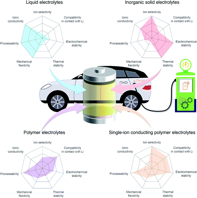 |
| | Fig. 1 Performance of different electrolyte materials. Radar plots of the properties of liquid electrolytes, inorganic solid electrolytes, polymer electrolytes, and single-ion conducting polymer electrolytes. | |
Among the variety of solid electrolyte technologies, polymer electrolytes have been attracting the most interest due to their small volume variation during the charging/discharging process, high level of safety, and ease-of-manufacturing.6 Commercial polymer electrolytes complexed with lithium salt are binary-ion conductors, in which both lithium cations and counter anions are mobile species (Fig. 2a). In general, anions move at least four times faster than lithium cations, as the motion of cations is highly coupled with Lewis basic sites in the polymeric host, and thus lithium cation transfer contributes only a small fraction (20%) of the overall ionic current.7 Besides, the anions accumulate at the interface between the electrode and electrolyte as there is no electrode reaction for anions, resulting in cell polarization and limited cycle life. In the early 1980s, Bannister et al. proposed a conceptual single lithium-ion conducting polymer electrolyte,8 in which the anions are tethered in the polymer matrix and most of the ionic current is carried by lithium transfer, leading to no concentration gradients and feasibly fast charging/discharging based on Newman's simulations.9–11 Furthermore, the dendrite growth would be minimized as predicted by the Chazlviel model,12,13 as lithium is plated and stripped evenly during the charging/discharging process. Indeed, single-ion conducting (SIC) polymer electrolytes hold much promise for next-generation batteries possessing outstanding safety, fast charging capability, and high energy density.14
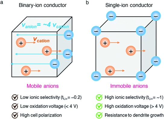 |
| | Fig. 2 Binary-ion conductor and single-ion conductor. Schematic illustration of (a) binary-ion conductors and (b) single-ion conductors, and their typical performance properties. | |
Along with their remarkable benefit and potential, the research field of SIC polymer electrolytes has been shown to substantially increase in both the number of published articles and citations, 238 and 7190 in the last decade (as of June 2021), respectively, indicating that SIC polymer electrolyte research is in a stage of vigorous development. To date, several reviews have summarized the progress of SIC polymer electrolytes with respect to the physico- and electro-chemical properties of solvent free electrolytes,14 gel electrolytes,15 and both types,16,17 which provide useful references for researchers in relevant fields. The motivation of this review is not only a summary of current achievement, but also to provide a comprehensive picture for future development in terms of design perspective, fabrication, electrochemical properties and standard characterization techniques.
2. Building blocks and strategies to achieve SIC polymers
Efforts have focused on developing SIC polymer electrolytes by covalently immobilizing anionic groups onto a polymer backbone, which only allows Li+ cations to be mobile through the polymer bulk (Fig. 2b). The selection of anionic groups and the structure of the polymer matrix play important roles in achieving a better ionic transport performance in SIC polymer electrolytes. The degree of negative charge delocalization in anionic groups has been shown to engender the ionic conductivity of SIC polymer electrolytes by weakening the dissociation energy of Li+ cations.18,19 In addition, controlling over the distance between anionic species in the polymer matrix is a critical factor in obtaining the ultimately high conductivity.20 In this regard, the structural configurations of SIC polymers will be detailed in the following section, and then synthetic and fabrication methods will be discussed.
2.1 Anionic groups
2.1.1 Carboxylate (–CO2−) anionic groups.
Carboxylate groups positioned in glycosaminoglycans interact with Lewis acids, such as metal ions and hydrogen donors, in the course of carrying out biological functions.21–23 Inspired by glycosaminoglycans, carboxylate groups have been anchored into polymer backbones as part of a side chain. In 1984, Bannister et al. for the first time demonstrated SIC polymer electrolytes by incorporating perfluoroalkyl carboxylate groups (–(CF2)3CO2−) into poly(methyl methacrylate) (PMMA) (Fig. 3a), exhibiting a high ionic conductivity of ∼2.5 × 10⁻⁶ S cm−1 at 60 °C.8 Tsuchida et al. prepared an analogous SIC polymer containing carboxylate anions (–CO2−) together with an oligo(oxyethylene) (–(OCH2CH2)–) side chain (Fig. 3b),24 which is a less electron-withdrawing group compared to the perfluoroalkyl group. The ionic conductivity of the analogous polymer reached as high as 10−8 S cm−1 at 60 °C, which was significantly lower by two orders of magnitude than those of the SIC polymer obtained by Banister et al.8 It is likely attributed to the greater tendency of Li+ to dissociate from the carboxylate group in the vicinity of the perfluoroalkyl group, and hence replacing the hydrocarbon alkyl group with a perfluoroalkyl group would be an effective way to improve the ionic conductivity. Although the carboxylate anionic groups have been grafted into a variety of polymer matrices, including methyl siloxane terminated polyethylene oxide-co-polymethyl lithium propionate siloxane,25 poly(oligo-oxyethylene methacrylate-co-alkali metal acrylamidocaproate),26 polystyrene-b-poly(lithium methacrylate-co-oligoethylene glycol methacrylate),27 and hyperbranched poly(ethylene oxide) (PEO),28 for further structural modification to achieve high ionic conductivity, the ionic transport through the polymer comprising carboxylate anionic groups has been limited due to high affinity to Li+ cations. Indeed, discrete Fourier transform calculation revealed that the metal affinities to Lewis bases increase in the following order: carboxylate > phosphate > N–sulfate anions > O–sulfate anions.,29 implying that carboxylate groups slow down the ionic transport of Li+ cations. Furthermore, the low stability of carboxylate groups in contact with high potential cathodes (particularly above 4 V) hinders their implementation in practical applications.14
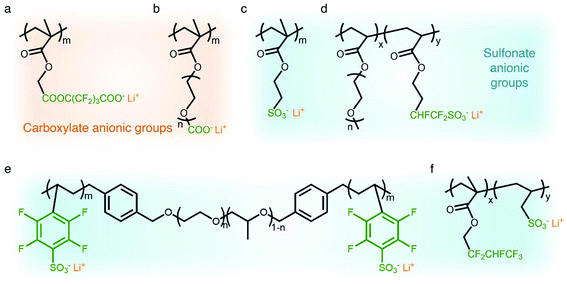 |
| | Fig. 3 Anionic groups for constructing SIC polymers. Chemical structures of (a and b) carboxylate-based SIC polymer electrolytes and (c–f) sulfonate-based SIC polymer electrolytes. Black: polymer backbone; olive: anion; orange: Li+ cation. | |
2.1.2 Sulfonate (–SO3−) anionic groups.
In contrast to the limited work on carboxylate groups for ion transport, the affinity of sulfonate groups for alkali cations has been used in developing Nafion membranes for selective ion transport in an aqueous solution30 as sulfonate groups exhibit a higher degree of dissociation with Li+ cations.29 A SIC polymer consisting of alkylsulfonate anions tethered into the PMMA backbone was proposed by Zhang and coworkers in 1991 (Fig. 3c).31 As the sulfonate anionic groups have a lower affinity to Li+ cations compared with carboxylate anionic groups, the ionic conductivity of a SIC polymer electrolyte blended with PEO increased to 1.8 × 10⁻⁷ S cm−1 at room temperature, which was 10 fold larger than that of its counterpart polymer prepared by Tsuchida et al.24 Nevertheless, its ionic conductivity was still too low for practical applications in battery cells so that many efforts have been devoted to using various strong electron-withdrawing groups (e.g. fluorine groups and phenyl) to replace the alkyl groups in terms of the negative charge delocalization theory reported by Armand.18,32–34 With the introduction of trifluorobutane sulfonate (–CHFCF2SO3−), Cowie et al. obtained a comb-branched copolymer with relatively high ionic conductivity (∼10−5 S cm−1) at room temperature (Fig. 3d).35 In 2017, Shao et al. synthesized a perfluorobenzyl sulfonate anion appended BAB triblock copolymer electrolyte, where A referred to PEO or poly(ethylene oxide-co-propylene oxide) and B represented poly(lithium 2,3,5,6-tetrafluorostyrene-4-sulfonate) (Fig. 3e),36 yielding a high ionic conductivity of 1.5 × 10⁻⁵ S cm−1 at 60 °C. In addition, strong electron-drawing groups can be located in close proximity to sulfonate groups rather than being located between sulfonate groups and the polymer backbone. Ji and coworkers prepared SIC block copolymers, poly(hexafluorobutyl methacrylate-co-lithium allyl sulfonate), where the flexible hexafluorobutyl moiety serving as an electron-withdrawing group facilitates Li+ cation dissociation from sulfonate groups (Fig. 3f).33 In the presence of fluorine units in the side chains, the block copolymer electrolyte reached outstanding ionic conductivity up to ∼10−4 S cm−1 at 80 °C. Overall results indicate that the sulfonate groups in the polymer matrix provide a decent affinity to Li+ cations for ion conduction, which can be further enhanced by incorporating electron-withdrawing groups.
2.1.3 Sulfonylimide (–SO2N(−)SO2–) anionic groups.
The findings from the aforementioned studies have motivated researchers to pay attention to anions possessing a low tendency to coordinate with alkali cations for electrolyte applications. The class of anions that allow the minimization of ion-pairing interaction is called weakly coordinating anions (WCAs). Particularly interesting are sulfonylimide anionic groups, where the presence of two highly electron-withdrawing groups on a nitrogen atom elevates the acidity of the hydrogen on the nitrogen atom,37,38 which first appeared in the literature in 1984.39 Such an anionic group in the polymer matrix lowers dissociation energy with Li+ cations in terms of their high delocalization of charge within the anions, promoting ionic transport,40 and hence SIC polymer electrolytes grafting a variety of sulfonylimide anions have been investigated (Fig. 4).41–44 The negative charge distribution in R–SO2N(−)SO2–X can be further broadened by introducing different electron-withdrawing groups, such as –CF3, –Ph and –PhCF3. For example, Zhang et al. presented a new series of polymeric fluorinated aryl sulfonimide tagged (polyFAST) anions as side chains, achieving high ionic conductivities (∼10−4 S cm−1 at 80 °C) when blended with PEO (Fig. 4a).41 Nguyen and coworkers designed a perfluoroether sulfonylimide based multiblock copolymer by incorporating more fluorinated groups into a polymer matrix, displaying ultrahigh ionic conductivity (∼10−3 S cm−1 at 30 °C) in the presence of ethylene carbonate (EC) (Fig. 4b).42 Indeed, the successful introduction of sulfonylimide anions into the polymer matrix dramatically improved the ion transport properties, contributing to significant progress in developing high-performance SIC polymer electrolytes. In addition to fluorinated groups, bis(benzene sulfonyl) imide anions have been widely studied due to the highly delocalized charge benzene rings at both ends. In 2014, Rohan et al. synthesized lithium poly(4-styrene sulfonyl (phenylsulfonyl)imide) (PSSPSILi) by consolidating bis(sulfonyl)imide anions to polystyrene, and its ionic conductivity reached up to 1.1 × 10⁻³ S cm−1 at room temperature in the presence of an organic solvent (Fig. 4c).43 Cao and coworkers copolymerized lithium 4-styrenesulfonyl(phenylsulfonyl)imide (SSPSILi) monomers with maleic anhydride (MA) units to form SIC polymers, where the dissociation of Li+ cations can be further enhanced due to the high dielectric constant and electron-withdrawing feature of MA units (Fig. 4d).44 With some amount of organic solvents, a SIC polymer electrolyte blended with poly(vinylidene fluoride-co-hexafluoropropylene) (PVDF-HFP) demonstrated a higher ionic conductivity of 2.67 × 10⁻³ S cm−1 at 25 °C with a high ionic selectivity of 0.98 in conduction.
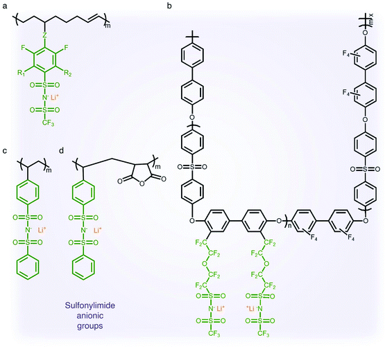 |
| | Fig. 4 Sulfonylimide anionic groups. (a–d) Chemical structures of sulfonylimide-based SIC polymer electrolytes. Black: polymer backbone; olive: sulfonylimide anion; orange: Li+ cation. | |
2.1.4 Borate (–B−–) anionic groups.
Fluorinated borate, [B(CF3)4]−, which is one of the classical WCAs, has been attracting great attention due to its remarkable chemical, thermal, and electrochemical stability,45,46 emerging as a promising counter anion for Li+ cation transfer in organic solvents.45 In order to incorporate the chemically stable fluorinated borate anions into a polymer matrix, endeavors have been focused on developing borate derivatives being suitable for polymerization, and two classes of borate derivatives have been introduced; bis(oxaloto)borate and tetraphenylborate.47–51 In 2004, Sun et al. incorporated lithium bis(allylmalonato)borate (LiBAMB) into a comb-branch polyacrylate polymer via hydrosilylation to form a network type SIC polymer electrolyte, exhibiting an ionic conductivity of 3.5 × 10⁻⁷ S cm−1 at room temperature (Fig. 5a).47 The optimization of the molar ratio of alcohol to borate groups (–OH/–B) enables a higher ionic conductivity (∼6 × 10⁻⁶ S cm−1) to be reached as well as an ultrahigh electrochemical working window (7 V) in the presence of propylene (PC),48 which was notable to achieve high voltage Li-ion batteries with high energy density (Fig. 5b). Xu et al. synthesized a lithium poly(4-vinylphenol) phenolate borate (LiPVPPB) SIC polymer electrolyte, where phenol rings were connected to borate atoms for further promoting the charge delocalization via π conjugation (Fig. 5c).49 Blended with PVDF-HFP, the electrolyte showed a high ionic conductivity of 4.4 × 10⁻⁴ S cm−1 in the presence of EC/PC and the ion selectivity in conduction could reach 0.91. However, it is noted that the B–O bond is not stable and sensitive to moisture, which is a challenge for practical applications.14 In comparison, tetraphenylborate is more stable and its distribution of negative charge can be further broadened due to the four electron-withdrawing phenyl rings. In 2012, Liang and coworkers grafted different types of tetraphenylborates onto polysiloxane to investigate the effect of electron-withdrawing groups (Fig. 5d).50 It has been shown that the electrolyte comprising borate anions with four perfluorinated phenyl rings (–C6F4(C6F5)3B) displayed the highest ionic conductivity (1.3 × 10⁻⁷ S cm−1 at 25 °C). In addition, Van Humbeck et al. proposed a porous aromatic frame (PAF)-based SIC interpretation network with borate centers (Fig. 5e).51 The ionic conductivity of the perfluorinated network (2.7 × 10⁻⁴ S cm−1 at 28 °C) was approximately 10 times greater than that of its non-fluorinated analogue, revealing that the affixation of fluorine groups to aromatic rings in the vicinity of borate weakens the interaction between Li+ cations and borate groups.
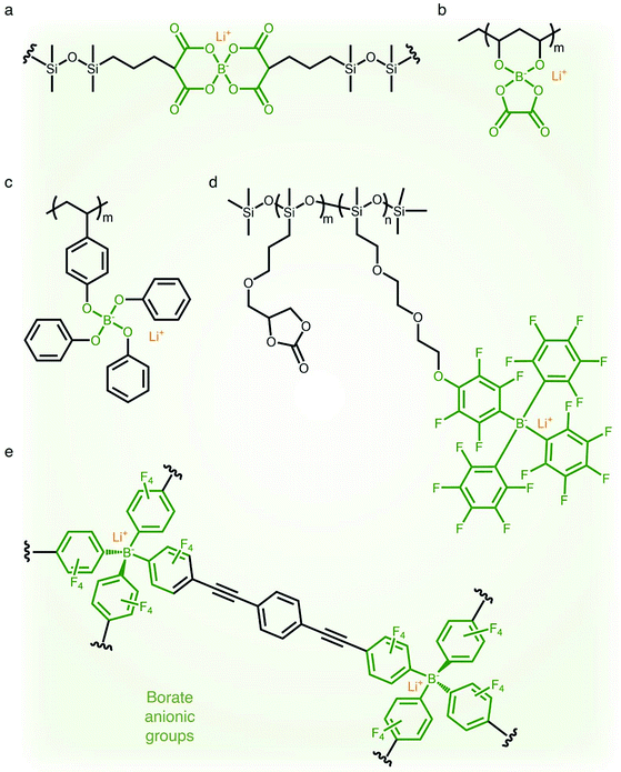 |
| | Fig. 5 Weakly coordinating borate anions. (a–d) Chemical structures of borate-based SIC polymer electrolytes. Black: polymer backbone; olive: borate anion; orange: Li+ cation. | |
2.2 Polymer matrices
2.2.1 Linear polymer matrices.
Linear polymers have been widely investigated as a framework in which anionic groups are directly conjugated to the linear backbone to form SIC polymer electrolytes. For example, anionic groups are anchored into the linear polystyrene structure to produce poly[lithium(4-styrenesulfonyl)-(trifluoromethanesulfonyl)imide] (LiPSsTFSI) (Fig. 6a), exhibiting an ionic conductivity of approximately 1.35 × 10⁻⁴ S cm−1 at 90 °C.52 The structure of the linear backbone has a significant impact on not only the ion-conducting properties but also the mechanical properties of electrolytes. The electron-donating polar groups on the backbone contribute to either solvating Li+ cations from anionic groups or providing sites for intra- or inter-chain cation hopping,53–56 so that the flexibility of the linear backbone is a critical factor in engendering ionic transport. Concomitantly, it is well known that the short- and long-range interactions between neighboring molecules in polymers determine their mechanical properties;57 therefore, the mechanical strength of electrolytes can be modified by the replacement of atomic units. Several approaches, such as an introduction of flexible molecular units or polar groups (e.g. –O–, C![[double bond, length as m-dash]](https://www.rsc.org/images/entities/char_e001.gif) O, and –N–), are implemented to foster ionic transport in polymeric matrices, and the integration of rigid units (e.g. benzene and heterocyclic groups) has been employed to ensure mechanical strength to endure the expansion/contraction of electrodes during battery operation. Typically, a siloxane (Si–O–Si) bond exhibits extraordinary dynamic flexibility due to not only the oxygen skeletal atom unencumbered by the side group but also a large bond angle of 143° with extreme deformability.58 Similarly, the ether (C–O–C) bond sequence is known to be a little flexible compared to the C–C covalent bond sequence.6,59–61 In 2013, Bouchet et al. took advantage of such molecular flexibility while designing SIC polymers. The polyether groups were introduced into an ABA triblock-copolymer to systematically tune ionic conductivities, where A corresponds to poly(styrene trifluoromethanesulphonylimide of lithium) and B refers to PEO (Fig. 6b).7 As a result, the ionic conductivity reached up to 1.3 × 10⁻⁵ S cm−1 at 60 °C. With the adoption of MA groups in the linear backbone of P(SSPSILi-alt-MA) alternating copolymer, two polar carbonyl units in MA and the alternating structure together facilitate dissociation as well as uniform distribution of Li+ cations along the chains, and the tensile properties of the polymer were enhanced by rigid MA groups.44
O, and –N–), are implemented to foster ionic transport in polymeric matrices, and the integration of rigid units (e.g. benzene and heterocyclic groups) has been employed to ensure mechanical strength to endure the expansion/contraction of electrodes during battery operation. Typically, a siloxane (Si–O–Si) bond exhibits extraordinary dynamic flexibility due to not only the oxygen skeletal atom unencumbered by the side group but also a large bond angle of 143° with extreme deformability.58 Similarly, the ether (C–O–C) bond sequence is known to be a little flexible compared to the C–C covalent bond sequence.6,59–61 In 2013, Bouchet et al. took advantage of such molecular flexibility while designing SIC polymers. The polyether groups were introduced into an ABA triblock-copolymer to systematically tune ionic conductivities, where A corresponds to poly(styrene trifluoromethanesulphonylimide of lithium) and B refers to PEO (Fig. 6b).7 As a result, the ionic conductivity reached up to 1.3 × 10⁻⁵ S cm−1 at 60 °C. With the adoption of MA groups in the linear backbone of P(SSPSILi-alt-MA) alternating copolymer, two polar carbonyl units in MA and the alternating structure together facilitate dissociation as well as uniform distribution of Li+ cations along the chains, and the tensile properties of the polymer were enhanced by rigid MA groups.44
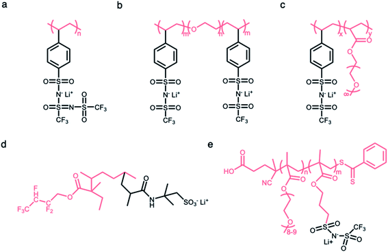 |
| | Fig. 6 Polymer matrices for constructing SIC polymers. Chemical structures of SIC polymer electrolytes with (a and b) linear polymer matrices and (c–e) branched polymer matrices. Black: anion and Li+ cation; pink: polymer matrices. | |
2.2.2 Branched polymer matrices.
The side chains tethered to the linear backbone are beneficial to decrease the crystallization of polymer matrices due to increased steric resistance,62–64 endowing the matrix with higher flexibility and ultimately high ionic conductivity. Thus, the flexible matrices form as a branched network consisting of functional side chains (e.g. flexible or polar molecular units) conjugated to the main linear backbone, and the immobilization of anionic groups to the branched matrices made this material a SIC polymer electrolyte. In 2013, Feng et al. designed a comb-like copolymer, lithium poly[(4-styrenesulfonyl) (trifluoromethanesulfonyl) imide-co-methoxy-polyethylene glycol acrylate] (Li[PSTFSI-co-MPEGA]), by utilizing oligomeric ethylene oxide (EO) segments as the side chains, resulting in the suppression of the crystallinity and the increase of mobility (Fig. 6c).65 The branched matrix raised the ionic conductivity by three orders of magnitude, and a maximum of 7.6 × 10⁻⁶ S cm−1 at 25 °C was reached. Likewise, two monomers (2,2,3,4,4-hexafluorobutyl methacrylate (HFMA) and 2-acrylamido-2-methylpropanesulfonic acid (AMPS)) were polymerized to a pre-irradiated polyvinylidene fluoride (PVDF) chain through graft polymerization (Fig. 6d).66 The grafted HFMA blocks not only reduce the crystallinity of the PVDF matrix but also facilitate the dissociation of Li ions along the chains due to their strong electron withdrawing fluorine groups. The PVDF based graft polymers showed a comparatively high ionic conductivity of 2.08 × 10⁻⁵ S cm−1 at 30 °C. Finally, the anionic groups can be fixed at the end of the short side chains for further enhancement of the ion mobility.67 Porcarelli et al. reported a poly(ethylene glycol) methylether methacrylate-co-poly(lithium1-[3-(methacryloyloxy)propylsulfonyl]-1-(trifluoromethylsulfonyl)imide), where anionic groups were introduced as part of the functionalization at the end of side chains, displaying a high ionic conductivity of 2.3 × 10⁻⁶ S cm−1 at 25 °C (Fig. 6e).68
2.2.3 Network matrices.
Network matrices have also been widely investigated to promote the mechanical properties and stability of SIC polymer electrolytes, while reducing their crystallinity. Network polymers are composed of anionic group nodes connected through linear linkers via covalent bonds.69–71 In 2019, Yu et al. prepared two SIC networks comprising tetrahedral X(OR)4− (X = Al, B) anions as crosslinking centers and soft fluorinated linkers (1H,1H,11H,11H-perfluoro-3,6,9-trioxaundecane-1,11-diol, FTEG) (Fig. 7a), which were coated to protect Li-metal anodes as an artificial solid-electrolyte interphase.69 After crosslinking with dynamic Al(OR)4− centers, the soft fluorinated segments improved the flexibility of the chains, further ensuring the flowability of the network. As a result, the polymer network displayed a liquid-like behavior at a low frequency, so that the dynamic SIC network (DSN) still remains in good contact with the anode during cycling. It was shown that the fluorinated chains were used to coordinate and transiently stabilize Li ions, facilitating the transport of Li ions along the fluorinated chains. Therefore, the ionic conductivity of the DSN could reach 3.5 ± 2.3 × 10⁻⁵ S cm−1 at 25 °C without the addition of a liquid plasticizer. Moreover, FTGE was less chemically reactive, so that the stability of the network was enhanced especially in the presence of a polar carbonate solvent. It is noted that the distance between anionic groups plays a significant role in efficient site-to-site Li-ion hopping transfer. Shin et al. built an anionic porous aromatic framework electrolyte consisting of weakly coordinating borate anion nodes and crosslinkable linkers via nucleophilic substitution (Fig. 7b).70 In this network, the cation hopping distance could be shortened due to its interpenetrated diamondoid network structure. As a result, the network electrolyte displayed a high lithium transference number (0.95) and a relatively high ionic conductivity (1.5 × 10⁻⁴ S cm−1) in the presence of minimal liquid plasticizer (30 wt%). Instead of using covalent bonds to form a network structure, Gan et al. synthesized a self-healing SIC triblock polymer by copolymerization of poly(ethylene glycol) methyl ether methacrylate (PEGMA), 2-(3-(6-methyl-4-oxo-1,4-dihydropyrimidin-2-yl)ureido)ethyl methacrylate (UPyMA), and SSPSILi, in which the network structure was established by hydrogen bonding of each branched polymer (Fig. 7c).72 With the introduction of UPyMA chains, the network electrolyte can be self-healed without any external stimuli after getting damaged on account of the quadruple hydrogen bonding between ureidopyrimidinone (UPy) groups, likely contributing to addressing safety concerns in practical applications. Also, the PEGMA chains endowed the network with comparative flexibility, resulting in a high ionic conductivity of 1.40 × 10⁻⁵ S cm−1 at 60 °C.
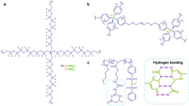 |
| | Fig. 7 Network polymer matrices. (a–c) Chemical structures of SIC polymer electrolytes with network matrices. Iris: network polymer matrices; olive: anionic center; orange: Li+ cation. | |
2.2.4 Others.
Some special macromolecules are designed to trap anions in electrolytes containing binary ions rather than the fixation of anionic groups into polymer matrices. In contrast to common SIC polymers, there are no tethered anionic groups in macromolecules but Lewis acid groups or calixarenes are employed to coordinate with anions for slowing down their mobility. Mehta et al. designed a series of Lewis acid-based anion acceptors by the introduction of boroxine rings (B3O3) (Fig. 8a).73 To obtain SIC electrolytes, a polymer host incorporating boroxine rings was mixed with lithium salts (e.g. LiCl and LiCF3SO3) and such Lewis acid groups impeded the motion of anions via Lewis acid–base interaction, providing Li-ion transference numbers in the range of 0.62–0.88 and a relative high ionic conductivity of 1.6 × 10⁻⁵ S cm−1 at 30 °C. Secondly, calix[2]-p-benzo[4]pyrrole (CBP) was incorporated into PEO electrolytes as an anion acceptor, in which calixarene groups trap CF3SO3− anions via hydrogen bonds (Fig. 8b).74 The lithium transference number increased from 0.23 to 0.78 with the addition of CBP, indicating that CBP forms stable complexes with CF3SO3− to inhibit the mobility of anions. Hybrid SIC polymer electrolytes have been synthesized by grafting organic blocks onto inorganic backbones as inorganic backbones (e.g. polysiloxane,50,75 organic aluminate polymers,76 SiO2,77,78 and Al2O3 (ref. 79)) to increase the ionic conductivities and mechanical properties of the composite. Siska et al. grafted organic blocks containing trifluoromethylsulfonamide and short oligoethers onto the polysiloxane backbone to yield SIC polymer electrolytes, showing an ionic conductivity as high as 1.2 × 10⁻⁶ S cm−1 at 25 °C in an optimal anion/oligoether ratio (Fig. 8c).75
 |
| | Fig. 8 (a–c) Chemical structures of SIC polymer electrolytes with other polymer matrices. | |
2.3 Strategies for SIC membrane fabrication
In order to integrate SIC polymers into battery cells as a solid-state electrolyte, it is necessary to be processable into membranes with acceptable mechanical strength to ensure proper function. A myriad of fabrication technologies have been applied to facilitate a focused push towards membrane fabrication for full cell integration, and some successful common methods will be summarized in the following section.
2.3.1 Casting.
A casting method refers to the solidification of a homogeneous solution, consisting of SIC polymer electrolytes and a suitable solvent, on an inert substrate (Fig. 9a), and such methods currently dominate the membrane fabrication technologies due to their low cost, universality, and operational simplicity. For instance, Rolland et al. dissolved 10 wt% (PS-b-P(OEGMA-co-MALi)) in tetrahydrofuran/methanol (50![[thin space (1/6-em)]](https://www.rsc.org/images/entities/char_2009.gif) :
:![[thin space (1/6-em)]](https://www.rsc.org/images/entities/char_2009.gif) 50 vol%) to generate a homogeneous solution, followed by casting onto Teflon films.27 Evaporation of the solvent renders them to freestanding membranes with a thickness ranging from 300 μm to 1 mm, showing an ionic conductivity of 2 × 10⁻⁵ S cm−1 at room temperature. However, it is worth mentioning that the evaporation speed usually has a strong effect on obtaining SIC membranes of high quality and consistency. Therefore, an optimal evaporation temperature and wind speed are always needed to be kept. In some cases, the casting method is time-consuming due to the slow evaporation process.
50 vol%) to generate a homogeneous solution, followed by casting onto Teflon films.27 Evaporation of the solvent renders them to freestanding membranes with a thickness ranging from 300 μm to 1 mm, showing an ionic conductivity of 2 × 10⁻⁵ S cm−1 at room temperature. However, it is worth mentioning that the evaporation speed usually has a strong effect on obtaining SIC membranes of high quality and consistency. Therefore, an optimal evaporation temperature and wind speed are always needed to be kept. In some cases, the casting method is time-consuming due to the slow evaporation process.
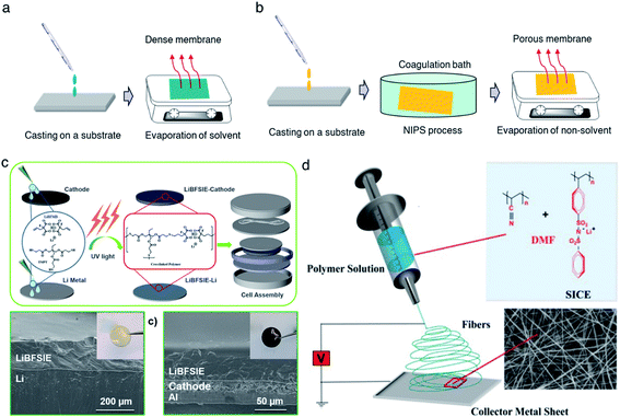 |
| | Fig. 9 Schematic illustration of membrane fabrication methods. (a) Casting method. (b) NIPS phrase separation. (c) In situ polymerization. Reproduced with permission.94 Copyright 2020, American Chemical Society. (d) Electrospinning technique. Reproduced with permission.96 Copyright 2017 Wiley. | |
Sometimes, some additives (e.g. aromatic polybenzimidazole (PBI),80 PVDF,43 and PVDF-HFP28,81) are also used to not only enhance the mechanical strength of the membrane and but also help the membrane formation.28 A self-standing membrane was prepared by casting a solution mixture of polymeric lithium tartaric acid borate (PLTB) and PVDF-HFP in dimethylformamide (DMF) solvent.82 After the removal of trace DMF under vacuum, there were no obvious cavities on the surface of the membrane. It was also shown that the dense membrane possessed a considerable tensile strength of 19 MPa under 53% strain after the introduction of PVDF-HFP.
2.3.2 Phase separation.
Compared with the casting method, phase separation has been aimed at the construction of a porous membrane for better plasticizer uptake via capillary condensation,83 which usually results in a higher ionic conductivity of SIC membranes.84 In general, phase separation methods can be categorized into three types: nonsolvent-induced phase separation (NIPS), vapor induced phase separation (VIPS), and liquid-extraction induced phase separation (LIPS).85 In the NIPS process, the exchange of solvent basically induces the phase separation. A homogeneous SIC polymer solution is firstly cast into a substrate, and then the substrate is immersed into a nonsolvent bath. The nonsolvent extracts the solvent from the membrane, leading to the formation of a two-phase structure in the membrane: polymer-rich phase (solvent rich) and polymer-poor phase (solvent poor). After the removal of the solvent, the polymer-rich and polymer-poor regions become a polymer matrix and a pore, respectively (Fig. 9b).80 Zhang et al. prepared a homogeneous solution comprising lithium poly(4,4′-dihydroxydiphenyl sulfone borate), PBI and N,N-dimethylacetamide.80 The solution was cast on a glass slide and then the sample was immersed in ethyl acetate immediately, yielding a highly porous membrane with a porosity of 92% and plasticizer uptake capability up to 275%. In addition, the tensile strength of the membrane reached 21.1 MPa, which was higher than that of the commercial Celgard separator due to the rigid aromatic polybenzimidazole. Secondly, the difference in solubility gives rise to phase separation in the VIPS process, contributing to the formation of phase-separated microstructures in the membrane.42,83,86,87 Chen et al. firstly prepared an interconnected microporous SIC membrane by the VIPS process.83 Lithiated polymer ionomers and PVDF-HFP were introduced into N-methyl-2-pyrrolidone (NMP) to yield a homogeneous solution. The solution mixture was subsequently added dropwise onto a glass plate, and then the solvent was slowly evaporated at 60 °C. PVDF-HFP was firstly sedimented due to the low solubility in NMP, leading to the aggregation of lithiated polymers. After complete removal of NMP, the aggregated lithiated polymers and PVDF-HFP collectively constructed an interconnected microporous membrane, facilitating the absorption of 151 wt% EC/DMC and reaching an ionic conductivity of 5.2 × 10⁻⁴ S cm−1 at 25 °C. Finally, the LIPS process is also an effective way to improve the porosity of the membrane.88 During the LIPS process, some additives (e.g. poly(ethylene glycol)) are firstly mixed with SIC polymers to construct membranes and subsequently removed by liquid extraction with a certain solvent, such as methanol and water, producing highly porous membranes.85
2.3.3
In situ polymerization.
In situ polymerization has drawn lots of attention to construct a dense SIC polymer electrolyte. Different from the casting method, the homogeneous solution is composed of lithium salt monomers, photo-initiators or thermal initiators, and some solvent. An ultraviolet (UV) radiation or thermal process initiates the polymerization of solution cast on a substrate, leading to a dense SIC polymer membrane.89–91 Especially, gel-type SIC polymer electrolyte membranes can trap more plasticizers during polymerization and have better compatibility with plasticizers due to the molecular level mixing, inducing a higher ionic conductivity.15 Besides, in situ polymerization can bring about a better interface between electrolytes and electrodes in the process of direct casting on the electrodes,92,93 lowering interfacial resistance and ultimately improving the ionic conductivity as well as stability of the electrolytes. Liu et al. prepared a boron-centered fluorinated SIC precursor by dissolving lithium bis(fluoroallyl)malonato borate with α,ω-dienes, trimethylolpropane tris(3-mercapto propionate) and 2,2-dimethoxy-2-phenylacetophenone in a solvent mixture of PC, EC and fluoroethylene carbonate (FEC).94 The precursor was cast on a Teflon mold and exposed to UV light to initiate the thiol–ene click reaction (Fig. 9c) for 15 min, and the resulting crosslinked SIC polymer membrane exhibits a Young's modulus of 383 kPa. In the battery performance test, the SIC precursor was added dropwise onto both the LFP cathode and Li metal to form SIC layers, enabling a better interface between the electrodes and electrolyte. Subsequently, the cell displayed a remarkable cyclability without significant degradation of capacity for 200 cycles.
2.3.4 Electrospinning.
The electrospinning technique has been used for generating a 1D porous nanofiber SIC membrane exhibiting a good ionic conductivity and stable electrochemical properties by taking advantage of its nanofibrous morphology, including a high surface-to-volume ratio, porosity and flexibility.95 Rohan et al. mixed PSSPSILi and polyacrylonitrile (PAN) in DMF to fabricate a SIC nonwoven nanofabric membrane using electrospinning (Fig. 9d).96 The diameter of the fibers was in the range of 40–100 nm, which contributed to a large surface area and porosity. As a result, the solvent uptake reached 700% in a short time, leading to a high ionic conductivity of 3.9 × 10⁻³ S cm−1 at ambient temperature. It is noted that the membrane also exhibited excellent electrochemical stability, a wide working window (5.2 V), steady cycle life, and outstanding performance at high C-rates, which correspond to a full discharge of the theoretical cathode capacity C in n h.
3. Three classes of SIC polymer electrolytes
Driven by their promising remarkable performance for next-generation lithium batteries, a wide variety of SIC polymer electrolytes have been designed and synthesized in order to possess higher ionic conductivity, better processability and a longer lifetime. In terms of the state and molecular structure, SIC polymer electrolytes can be roughly sorted into three categories as follows.
3.1 Solvent-free SIC polymer electrolytes
Solvent-free SIC polymer electrolytes can be defined as polymer electrolytes without any organic solvent plasticizers. Li+ cation conduction in solvent-free SIC polymers primarily depends on their polymeric characteristics, and it has been understood that Li+ cation conduction in solvent-free SIC polymer electrolytes occurs in a consecutive mechanistic process.54 First, Li+ cations coordinate with polar groups (e.g. –O–, –S–, and –N–) in the polymer chains over the course of polymeric segmental motion, facilitating the Li+ cation dissociation from the anionic sites. The Li+ cations dissociated migrate through anionic site-to-site hopping within the polymer matrix. Typically, the ionic conductivities of solvent-free SIC polymer electrolytes are in the range of 10−7 to 10−5 S cm−1 at elevated temperature,6,62 and those polymer electrolytes outperform the conventional liquid and gel electrolytes in terms of safety concerns.6,97
3.2 SIC gel polymer electrolytes
The ionic conductivity of solvent-free SIC polymer electrolytes can be significantly improved at ambient temperature by introducing a certain amount of organic solvent, forming SIC gel polymer electrolytes. Polar organic solvents represent a high dielectric permittivity and low viscosity, and hence organic solvents have been found to facilitate ion dissociation in solid electrolytes.97,98 EC, dimethyl carbonate (DMC), propylene carbonate (PC), and gamma butyrolactone (GBL) have been used as organic plasticizers in polymer electrolytes. At a low solvent loading (<33 wt%), the solvated Li+ cations transport by hopping coordination sites in the polymer chain due to the lack of residual organic solvent molecules in the electrolyte.99,100 With increasing the content of plasticizers, the ion solvation and transport behaviors become similar to those of liquid electrolytes.101 With the help of organic solvents, the ionic conductivity of SIC gel polymer electrolytes reached as high as 10−3 S cm−1 at room temperature, which is much higher than that of solvent-free SIC polymer electrolytes (usually less than 10−5 S cm−1).43,44,85 However, the design of SIC gel polymer electrolytes lays on a trade-off between high ionic conductivity and low mechanical strength/safety concerns with increasing solvent amount.
3.3 SIC poly(ionic liquid) (PIL) electrolytes
Ionic liquids (ILs) are molten organic salts (e.g. lithium bis(trifluoromethanesulfonyl)imide, LiTFSI), which have been proven to show a good thermal stability and electrochemical performance.102,103 Inspired by their remarkable features, poly(ionic liquid)s (PILs) are designed to take advantage of both IL characteristics and properties of polymers. PILs consist of polymeric backbones with IL species in the repeating unit, in particular, and anion species are anchored into the polymer backbone to foster the SIC PIL electrolytes. Porcarelli and coworkers synthesized an ionic monomer of lithium 1-[3-(methacryloyloxy)-propylsulfonyl]-1-(trifluoromethanesulfonyl)imide (LiMTFSI),68 which then reacted with PEGMA to form a SIC PIL electrolyte by reversible addition–fragmentation chain-transfer (RAFT) polymerization. The ionic conductivity of the obtained SIC PILs reached up to 10−5 S cm−1 at elevated temperature (55 °C). Interestingly, SIC PILs were thermally stable up to 170 °C even though they exhibited rubber-like and wax-like behaviors, outperforming conventional liquid electrolytes in terms of thermal stability but evincing viable ionic conductivity for battery operation. In 2018, Porcarelli et al. further synthesized four novel ionic liquid monomers by introducing a long, flexible and perfluorinated side chain.104 Through copolymerization with PEGMA, the highest ionic conductivity of the SIC coPILs could reach 1.9 × 10⁻⁶ S cm−1 at room temperature. Recently, Zhang and coworkers also tuned the electronic and steric properties of anionic side chains in SIC PILs to obtain a high ionic conductivity of ∼10−4 S cm−1 at 80 °C when blended with PEO. However, the lower ionic conductivities of SIC PIL electrolytes still cannot meet the requirements of practical applications.
4. Electrochemical performance in Li metal batteries
Ever since the conceptualization of the SIC polymer electrolyte in 1984,8 most of the efforts have mainly concentrated on the modification of anionic groups and polymer matrices to improve the ionic conductivity. In recent years, a significant enhancement in the ionic conductivity of SIC polymer electrolytes has shifted the paradigm to investigate the requisite electrochemical properties for battery operation. In view of this, the requirement of SIC polymer electrolytes for battery operation will be discussed in the following parts according to their electrochemical properties, including but not limited to ionic conductivity, ion selectivity in conduction, the electrochemical stability window, galvanostatic cycling, and practical performance in battery prototypes. The electrochemical properties of the state-of-art SIC polymer electrolytes are summarized in Table 1.
Table 1 Ionic conductivity, transference number, thermal stability, and electrochemical working window for the best performing SIC solvent-free polymers, gel-polymers, and poly(ionic liquid)s reported to datea
| Type |
System |
Ionic conductivity |
t
Li+
|
Thermal stability (°C) |
Working window (V vs. Li/Li+) |
Ref. |
|
σ (S cm−1) |
T (°C) |
|
LiPSTFSI + VIPS/PEO: poly-lithium (4-styrenesulfonyl) (trifluoromethanesulfonyl)imide + poly 3-(1-vinyl-3-imidazolio)propanesulfonate/poly(ethylene oxide); PDMS-g-MPA Li10+/PEGMEMA30: poly(dimethylsiloxane)-g-lithium 1-[3-(methacryloyloxy) propylsulfonyl]-1-(trifluoromethanesulfonyl)-imide/poly(ethylene glycol) methyl ether methacrylate; crosslinked TFSI: 3-sulfonyl(trifluoromethane sulfonyl) imide propyl acrylate ionic monomer based network; polyFAST/PEO: poly[(4-styrenesulfonyl) (trifluoromethanesulfonyl)imide]/poly(ethylene oxide); poly(PEOMATFSI–Li+): poly(poly(ethylene oxide) methacrylate lithium sulfonyl (trifluoromethylsulfonyl)imide); SICPE/PVdF-HFP: lithium (4-carboxyl benzene sulphonyl)imide polymer blended with poly(vinylidene fluoride-co-hexafluoropropylene); PEO8–LiPCSI: poly(ethylene oxide)/lithium poly[(cyano)(4-styrenesulfonyl)imide]; LiBFSIE: (lithium bis(allylmalonato) borate)-pentaerythritol tetrakis(2-mercaptoacetate); LiBNMB: lithium bis(non-8-enyl-malonato)borate polymer; ANP-5: lithium tetrakis(4-(chloromethyl)-2,3,5,6-tetrafluorophenyl)borate network polymer; PSI-PES-FPES-block copolymer: lithium perfluorinated sulfonimide and nonpolar block copolymer; LPD@PVDF: lithium bis(allylmalonato) borate polymer composited with electrospun poly(vinylidienefluoride); PAGELS: poly(allyl glycidyl ether-lithium sulfonate); poly(PEGM)-b-poly(LiMTFSI): poly(lithium 1-[3-(methacryloyloxy)propylsulfonyl]-1-(trifluoromethylsulfonyl)imide) and poly(ethylene glycol) methyl ether methacrylate copolymer; LiPSsTFSI/PEO: poly[(4-styrenesulfonyl) (trifluoromethyl(S-trifluoromethylsulfonylimino)sulfonyl)imide]/poly(ethylene oxide); poly(LiMTFSI)/PEO copolymer: poly(lithium 1-[3-(methacryloyloxy)propylsulfonyl]-1-(trifluoromethylsulfonyl)imide)/poly(ethylene oxide) copolymer.
|
| Solvent-free |
LiPSTFSI + VIPS/PEO |
8.4 × 10⁻⁵ |
90 |
0.92 |
350 |
4.8 |
113
|
| PDMS-g-MPA Li10+/PEGMEMA30 |
4.7 × 10⁻⁶ |
RT |
0.85 |
300 |
4.2 |
91
|
| Crosslinked TFSI |
10−5 |
90 |
0.85 |
300 |
— |
122
|
| PolyFAST/PEO |
∼10−4 |
80 |
∼0.8 |
— |
5.0 |
41
|
| poly(PEOMATFSI-Li+) |
1.6 × 10⁻⁴ |
90 |
0.97 |
— |
>5.0 |
131
|
| SICPE/PVdF-HFP |
5.2 × 10⁻⁴ |
20 |
0.90 |
385 |
4.6 |
81
|
| PEO8–LiPCSI |
1.6 × 10⁻⁴ |
85 |
0.84 |
300 |
5.5 |
142
|
| Gel |
LiBFSIE |
8.4 × 10⁻⁴ |
RT |
0.93 |
240 |
5.2 |
117
|
| LiBNMB |
2.5 × 10⁻⁶ |
22 |
∼1 |
200 |
— |
123
|
| ANP-5 |
1.5 × 10⁻⁴ |
RT |
0.95 |
290 |
4.5 |
70
|
| PSI–PES–FPES-block copolymer |
>10−3 |
30 |
∼1 |
300 |
5.0 |
42
|
| LPD@PVDF |
1.3 × 10⁻³ |
25 |
0.92 |
— |
6.0 |
90
|
| PILs |
PAGELS |
1.5 × 10⁻³ |
25 |
0.98 |
— |
— |
106
|
| Poly(PEGM)-b-poly(LiMTFSI) |
1.2 × 10⁻⁵ |
55 |
0.83 |
170 |
4.5 |
68
|
| LiPSsTFSI/PEO |
1.4 × 10⁻⁴ |
90 |
0.91 |
300 |
4.5 |
52
|
| Poly(LiMTFSI)/PEO copolymer |
1.0 × 10⁻⁴ |
70 |
0.91 |
315 |
4.0 |
168
|
4.1 Ionic conductivity
As electrolytes serve as the ionic pathway between electrodes, leading to the determination of electron flow through an external circuit, the capability of ion transport in the electrolyte is one of the main criteria to determine the battery performance. The ionic conductivity is a measure of the amount of charge being moved in a given electric field. Ion mobility has been characterized using the radiotracer diffusion technique105 and pulsed-field gradient nuclear magnetic resonance (PFG-NMR) measurements,106 but such techniques are problematic in specific cases where radioactive isotopes are hard to secure and equipment access is limited due to high cost, respectively. Therefore, alternating current (AC) impedance spectroscopy has become a preferred method to determine the ionic conductivity of electrolytes due to its universality. Once a low AC electric field perturbates the ions across the electrolytes, ion transport is reflected in the complex impedance as a function of frequency. With the help of an equivalent circuit where parallel circuit consisting of a resistance and constant phase element (CPE) is connected with another CPE in series, ionic conductivity is given as the inverse of resistance with geometrical consideration in the sandwiched configuration between two blocking electrodes (Fig. 10).107 Variable temperature conductivity is used for determining the activation energy of diffusive ionic conduction in electrolytes, where hopping-type mechanisms are valid (Fig. 11), and the temperature dependence of ionic conductivity can be reasonably described by the following equation:108–110| |  | (1) |
where σ0 and Ea are a pre-exponential factor and activation energy, respectively. kBT and T indicate the Boltzmann constant and temperature, respectively. At temperatures above the glass transition point, the temperature-dependent ionic conductivity no longer follows the Arrhenius behavior as ionic transport is dominantly determined by the effective viscosity of the electrolyte rather than a physical hopping barrier. Considering the polymer viscosity decreasing with temperature, the more specific Vogel–Tammann–Fulcher (VTF) relation (eqn (2)) is widely used to describe ion conductivity in polymer electrolytes.111,112| |  | (2) |
where A and B are pre-exponential factors, T is the temperature, and T0 is a reference temperature.
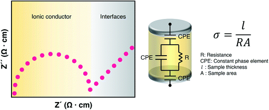 |
| | Fig. 10 Ionic conductivity characterization. Representative Nyquist plot of an ionic conductor sandwiched with blocking electrodes (left) and its equivalent circuit model for ionic conductivity measurement (right). | |
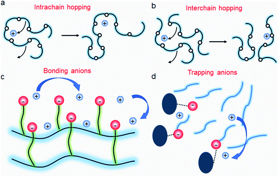 |
| | Fig. 11 Ion transport in a polymer electrolyte. (a) Intrachain hopping, (b) interchain hopping, (c) anionic site-to-site hopping, and (d) cation diffusion, while anions are trapped. | |
It has been known that the requisite ionic conductivity of the electrolytes is approximately 10−3 S cm−1 for battery operation.14 The cation transfer in the electrolyte containing binary ions exhibits minor contribution to the overall current, while the ionic current in the SIC polymer electrolyte is mainly carried by Li+ cation transfer, which leads to lowering the requisite ionic conductivity of SIC polymer electrolytes down to 10−4 S cm−1.14 In order to achieve the target, many efforts have been dedicated to amending solvent-free SIC polymers, SIC gel polymers and SIC polyionic liquids, and two representative approaches are summarized in Fig. 12, i.e. control over the Li+ cation affinity of anionic groups as well as the flexibility of polymer matrices.62
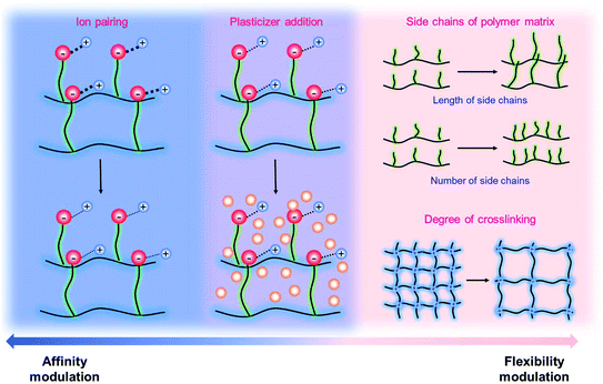 |
| | Fig. 12 Approaches to increase conductivity. Navy indicates the modulations in ion-pairing, whereas pink corresponds to polymer flexibility modifications. Purple describes the combination of affinity and flexibility changes. | |
The incorporation of varied anionic groups, such as carboxylate, sulfonate, sulfonylimide, and borate anions, into a polymer matrix is an intuitive and straightforward strategy to modulate the ion dissociation, which plays an important role in dictating the ionic conductivity. Weakening ion-pairing with different anionic functional groups and electron-withdrawing groups has been discussed in Section 2.1, so that we detail other approaches to soften ion-paring of SIC polymer electrolytes. Lu et al. employed monomeric zwitterion 3-(1-methyl-3-imidazolio)propanesulfonate (MIPS) and polymeric zwitterion poly-3-(1-vinyl-3-imidazolio)propanesulfonate (VIPS) to weaken the ion-pairing between Li+ cations and SIC poly(lithium 4-styrenesulfonate)/PEO and LiPSsTFSI/PEO electrolytes,113 as shown in Fig. 13a. In both polymeric systems, the ionic conductivity increased by at least one order of magnitude with the addition of zwitterions (Fig. 13b), reaching as high as 8.39 × 10⁻⁵ S cm−1 at 90 °C. The exceptional ionic conductivity was attributed to the enhanced dissociation of Li+ cations in tandem with the plasticization of polymer matrices by addition of zwitterions. Liquid plasticizers, such as EC, DMC, FEC, and PC, have been shown to facilitate not only ion dissociation,114 but also polymer segmental motion,115,116 helping to rationalize the observed high ionic conductivity in polymer electrolytes. Zhang et al. polymerized the monomers of LiPSsTFSI, pentaerythritol tetrakis(2-mercaptoacetate) (PETMP) and pentaerythritol tetraacrylate to form a crosslinked network structured polymer,117 as shown in Fig. 13c. The gel network polymer exhibited an outstanding ionic conductivity of 0.84 mS cm−1 at room temperature in the presence of EC/DMC plasticizer (Fig. 13d), which is far beyond the requite ionic conductivity for battery operation. Similarly, a Li-containing boron-centered fluorinated SIC polymer gel electrolyte (LiBFSIE) showed a remarkable ionic conductivity of 2 × 10⁻⁴ S cm−1 at 35 °C upon addition of PC/EC/FEC plasticizer.94 The incorporation of plasticizers to form gel polymer electrolytes has significantly enhanced ion conductivities,118,119 but large amounts of flammable organic solvent give rise to safety hazards. Non-flammable ionic liquids were introduced to take advantage of plasticizers without sacrificing safety concerns. Wang et al. proposed a novel ion gel polymer electrolyte consisting of poly(diallyldimethylammonium) bis(trifluoromethanesulfonyl)imide (PDADMA TFSI), trimethyl(isobutyl)phosphonium bis(fluorosulfonyl)imide (P111i4FSI), and lithium bis(fluorosulfonyl)imide (LiFSI) (Fig. 13e), having a high ionic conductivity of 0.28 mS cm−1 at 30 °C (Fig. 13f).120 PFG-NMR measurement suggested that the diffusion of anionic species was suppressed somehow compared to Li+ cation diffusion, resulting in the formation of a SIC polymer electrolyte even though the anionic groups were not tethered into the polymer matrix. Indeed, the polymeric ionomer host impregnating ionic liquids provided an effective way to yield highly conductive polymer electrolytes with improved Li+ cation transport.
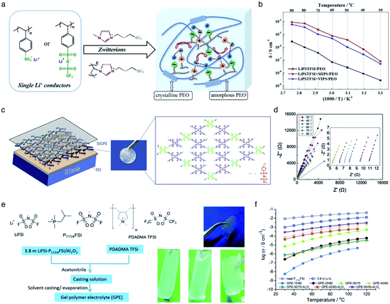 |
| | Fig. 13 Weakening ion-pair for enhanced conductivity. (a) Synthetic scheme of LiPSsTFSI/PEO electrolytes. (b) Arrhenius plot of LiPSsTFSI/PEO electrolytes at differing temperatures in the absence and presence of zwitterions. (a) and (b) are reproduced with permission.113 Copyright 2020, Elsevier. (c) Schematic illustration of LiBFSIE and its chemical structure. (d) Nyquist plots of LiBFSIE at various temperatures. (c) and (d) are reproduced with permission.117 Copyright 2020, Elsevier. (e) Schematic preparation procedure and pictures of SIC ion gel electrolytes. (f) Temperature-variable ionic conductivities of SIC ion gel electrolytes with varying compositions, neat P111i4FSI and 3.8 M LiFSI. (e) and (f) are reproduced with permission.120 Copyright 2017, Royal Society of Chemistry. | |
It is widely understood that cation migration occurs through re-coordination along the polymer matrix,53,54 and the segmental motion of polymer provides either cation hopping sites or a pathway for cations to be transported.55,56 Hence, the importance of polymer flexibility has been recognized in the enhancement of the ionic conductivity of SIC polymers. Zhao et al. demonstrated a concept of accelerated segmental dynamics in a polymer using both a flexible polymer backbone and side chains (Fig. 14a).121 Softening the polymer backbone improved the ionic conductivity by an order of magnitude while a significant ionic conductivity enhancement was found by grafting the flexible side chains, achieving a reasonable ionic conductivity of 4.7 × 10⁻⁶ S cm−1 at ambient temperature (Fig. 14b and c). The molecular structure–ionic conductivity relationship of polymer networks comprising an acrylate polymer backbone and PEO side chains was revealed in terms of the degree of crosslinking and the side chain length (Fig. 14d).122 Shen et al. found that a high degree of crosslinking sacrifices ionic conductivity up to 60% of magnitude (Fig. 14e), whereas ionic conductivity substantially increases with the side chain length (Fig. 14f). Similar results were found in a SIC gel polymer electrolyte synthesized by thiol–ene crosslinking polymerization of lithium bis(8-nonenylmalonato) borate and di-/tri-thiols.123 As shown in Fig. 14g, the ionic transport was strongly correlated with the network crosslinking density. Namely, tightly crosslinked gels exhibit lower Li+ cation conductivities (0.82 × 10⁻⁶ S cm−1) compared to gels possessing less crosslinking density (their conductivity is 2.5 × 10⁻⁶ S cm−1) due to the confined segmental motion of the polymer. Zhang et al. conducted parametric studies to improve the ionic conductivity of poly(solvate ionic liquid) (polySIL),41 including the electronic structure of the anionic sites, the inter-anionic group spacing, and the molecular interaction with the solvation molecules/segments (Fig. 14h). A systematic variation of the chemical structure of poly SIL enabled us to disclose that an extension of the distance between anionic sites provides higher conductivity.
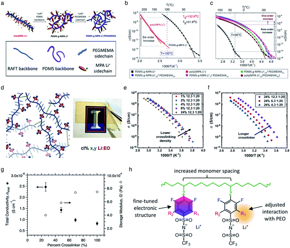 |
| | Fig. 14 Softening polymer matrices for conductivity improvement. (a) Schematic illustration of the flexible backbone and side chain concept to improve the ionic conductivity of SIC polymer electrolytes. (b) Ionic conductivity of poly(dimethylsiloxane)-g-lithium 1-[3-(methacryloyloxy) propylsulfonyl]-1-(trifluoromethanesulfonyl)-imide (PDMS-g-MPA Li+) and poly(MPA Li+) at variable temperatures. (c) Arrhenius plot of PDMS-g-MPA Li+, (PDMS-g-MPA Li+)x/PEGMAy, and poly((MPA Li+)10/PEGMA30). (a–c) are reproduced with permission.121 Copyright 2020, American Chemical Society. (d) A cartoon and photograph of the gel electrolytes with different crosslinking densities. Temperature dependence of conductivity for SIC polymer electrolytes with (e) various crosslinking degrees and (f) varying lengths of the linker. (d–f) are reproduced with permission.122 Copyright 2020, Wiley. (g) Modulus and conductivity of SIC polymer electrolytes with different linker concentrations. Reproduced with permission.123 Copyright 2017, Royal Society of Chemistry. (h) Structural features of polyFAST salts. Reproduced with permission.41 Copyright 2021, American Chemical Society. | |
4.2 Ion selectivity in conduction
Ion selectivity in conduction is termed the ion transference number, and the lithium cation transference number (tLi+) is defined as the ratio of current carried by the Li+ cation to the total current across the electrode cell as shown in eqn (3).| |  | (3) |
where ILi+ and Iothers represent the current imparted by Li+ cation and other ion transport, respectively. The transference number has been determined by multiple structural and electrochemical approaches. PFG-NMR is one of the typical structural characterization tools to obtain ion diffusion coefficients,106 but it is often challenging to use for solid state electrolytes due to the extremely short transverse relaxation time in solid state materials.124 Although electrochemical characterization, including Hittorf, moving boundary, and electromotive force methods, has been successfully made to determine the transference number in liquid electrolytes,125–127 they have been difficult to use for solid state ionic conductors.128 Potentiostatic polarization methods monitor the current changes upon small polarization across the electrolytes sandwiched with non-blocking electrodes (i.e. lithium electrodes for the lithium ion transference number),129 and they have become the standard for solid state electrolytes owing to their capability to apply to numerous material systems. Zugmann et al. demonstrated that the transference numbers of liquid electrolytes obtained from different measurement techniques are comparable, as shown in Table 2.130
Table 2 Lithium transference number of lithium difluoro mono(oxalato)borate in a solvent mixture of ethylene carbonate and diethyl carbonate determined by different methods. Reproduced with permission.130 Copyright 2011, Elsevier
| Method |
Concentration (M) |
t
Li+
|
| Galvanostatic polarization |
0.10 |
0.38 ± 0.048 |
| 1.0 |
0.33 ± 0.05 |
| Potentiostatic polarization |
0.1 |
0.38 ± 0.006 |
| Electromotive force |
1.0 |
0.35 ± 0.041 |
| PFG-NMR |
0.051 |
0.441 ± 0.0074 |
| 0.50 |
0.448 ± 0.0074 |
| 0.70 |
0.451 ± 0.0074 |
| 0.83 |
0.456 ± 0.0074 |
| 0.93 |
0.458 ± 0.0074 |
In SIC polymer electrolytes, the transference number has been found to approach unity using structural and electrochemical techniques as the mobility of anions is limited by their unique structural configuration. Buss et al. synthesized a SIC polyionic liquid electrolyte by replacing small counterions with poly(allyl glycidyl ether-lithium sulfonate) (PAGELS) anions,106 and the self-diffusion of PAGELS anion and Li+ cation species was characterized using 1H, 19F, and 7Li PFG-NMR spectroscopy. The diffusion coefficients of polyionic liquid electrolytes were determined from the slope of the relationship between the free diffusion echo signal attenuation (I/I0) and experimental parameters, which can be described as eqn (4):
| |  | (4) |
where
γ is the gyromagnetic ratio of the observed isotopes ,
δ is the length of the gradient pulse,
Δ is the time between pulses, and
τ is the gradient ringdown delay (
Fig. 15a). The self-diffusion coefficient of
7Li species was shown to be an order of magnitude greater than that of
1H species in the PAGEL anions (
Fig. 15b), resulting in a high transference number in a range of
tLi+ = 0.8–0.98.
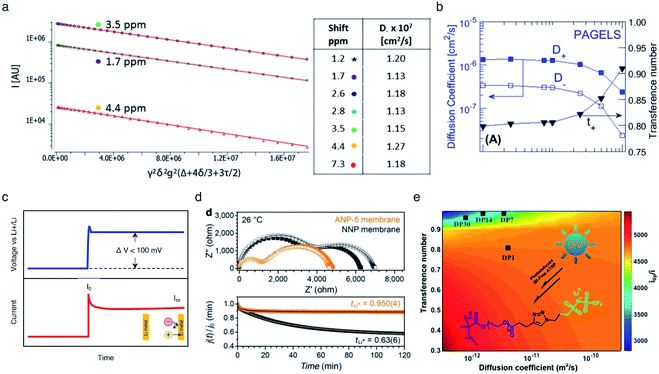 |
| | Fig. 15 Ionic selectivity in conduction of SIC polymer electrolytes. (a) Integrated intensity of three proton NMR peaks of 0.5 M PAGELS solution, and their self-diffusion coefficients. (b) Self-diffusion coefficients, measured by using PFG-NMR of the Li+ (D+) and anion (D−) and the Li+ transference number. (a) and (b) are reproduced with permission.106 Copyright 2017, American Chemical Society. (c) Representative DC voltage step and resulting current response applied to a symmetric Li|electrolyte|Li cell during Li+ transference number measurement. (d) Impedance spectra and current decay curves for ANP-5 and binary ion conducting membranes before and after polarization. Reproduced with permission.70 Copyright 2019, Wiley. (e) Contour plots of electrolytes with different Li+ diffusion coefficients. Reproduced with permission.131 Copyright 2017, American Chemical Society. | |
The transference numbers acquired by electrochemical methods have been shown to be extremely close to unity. In general, the current decay is recorded over time under a small applied potential (<100 mV) across a symmetric Li|electrolyte|Li cell (Fig. 15c). In a real system, the charge transport resistance at the electrodes is affected by the applied potential, and thus in order to account for this, the impedance spectrum was taken before and after applying potential. Considering all the factors above, the transference number can be calculated by using eqn (5):
| |  | (5) |
where
iss and
i0 are the steady state current and the initial current;
R0 and
Rss are the charge transfer resistances before and after the application of the step voltage (Δ
V).
As non-blocking Li metal electrodes are employed to enable Li+ cation transfer at the interface, two processes are usually observed in the Nyquist impedance plot (Fig. 15d top). The higher frequency feature corresponds to the ionic resistance, and the lower frequency feature represents the charge transfer resistance of Li+ cations crossing the electrolyte|Li(s) interface. The transference number of the SIC network polymer developed by Shin et al. was nearly unity (tLi+ = 0.9504) (Fig. 15d bottom), rationalizing that lithium cations serve as the only mobile species in a long range. In contrast, the transference number of binary ionic conducting analogous was substantially lower (tLi+ = 0.636). Besides, Li et al. prepared a SIC homopolymer electrolyte using click chemistry and photoinduced metal-free atom-transfer radical polymerization.131 The monomer had some degree of anionic mobility (tLi+ = 0.82), whereas anions became highly localized to the immobile PEO domain of the homopolymer, manifesting a high transference number (tLi+ = 0.95–0.99) (Fig. 15e).
4.3 Electrochemical stability window
Battery cell voltage is determined by the difference in chemical potential between the anode and the cathode chose. Concurrently, unfavorable electrochemical reduction and oxidation of electrolytes induce an increase in internal resistance at the interface, leading to capacity loss. Thus, the selection of electrodes is limited by the electrochemical stability of electrolytes; the chemical potential of the anode should be located below the lowest unoccupied molecular orbital of the electrolyte, whereas the chemical potential of the cathode lies above the highest occupied molecular orbital (HOMO) of the electrolyte for stable battery operation.132 The electrochemical stability is an important figure of merit for electrolyte study,133 and the electrochemical stability window is termed the voltage range in which no obvious reaction occurs on the electrode. The electrochemical stability is determined at low scan rates to avoid kinetic polarization using cyclic voltammetry with a three-electrode configuration. Lithium plating and stripping allow a reversible redox process at low potentials, while irreversible oxidation is observed at a high voltage limit. The stability window is defined as the distance between this reversible redox process and any irreversible oxidation.
Binary ion-conducting electrolytes have been often found to have a relatively narrow electrochemical stability window of 4–4.3 V (vs. Li/Li+)134–138 as the oxidation decomposition at the high voltage limit is likely attributed to the presence of mobile anions.7,139 In contrast, in SIC polymer electrolytes, the stationary anions can only be oxidized at the electrolyte–electrode interface and their strong electron-withdrawing capability can further lower the HOMO level of the electrolyte,140,141 affording improved electrochemical stability. For example, Borzutzki et al. prepared a homopolymer-typed SIC polymer electrolyte featuring a tethered anionic polysulfonylamide segment on the polymer backbone (inset of Fig. 16a),81 which was utilized as a solid-state electrolyte in LiNi1/3Mn1/3CO1/3O2 (NMC111)/Li cells. Polymer films with different weight ratios of PVDF-HFP to the SIC polymers (1![[thin space (1/6-em)]](https://www.rsc.org/images/entities/char_2009.gif) :
:![[thin space (1/6-em)]](https://www.rsc.org/images/entities/char_2009.gif) 1, 3
1, 3![[thin space (1/6-em)]](https://www.rsc.org/images/entities/char_2009.gif) :
:![[thin space (1/6-em)]](https://www.rsc.org/images/entities/char_2009.gif) 5, and 1
5, and 1![[thin space (1/6-em)]](https://www.rsc.org/images/entities/char_2009.gif) :
:![[thin space (1/6-em)]](https://www.rsc.org/images/entities/char_2009.gif) 3) were prepared for electrochemical studies. The SIC polymer films with a 1
3) were prepared for electrochemical studies. The SIC polymer films with a 1![[thin space (1/6-em)]](https://www.rsc.org/images/entities/char_2009.gif) :
:![[thin space (1/6-em)]](https://www.rsc.org/images/entities/char_2009.gif) 3 ratio show superior oxidative stability up to 4.6 V (vs. Li/Li+) (Fig. 16a). Yuan et al. designed a new SIC lithium poly[(cyano) (4-styrenesulfonyl) imide] (LiPCSI) polymer with the combination of PEO (inset of Fig. 16b).142 The tailored PEO8–LiPCSI exhibited a high oxidation potential (5.53 V (vs. Li/Li+)), due to the highly delocalized anion moiety and the oxidation resistance of the cyano group (Fig. 16b). Not surprisingly, the SIC PILs also possess a broad electrochemical stability window. Porcarelli et al. synthesized SIC block copolymer polyelectrolytes comprising LiMTFSI and PEGMA blocks via RAFT polymerization (Fig. 16c),68 showing a wide electrochemical stability window up to 4.5 V (vs. Li/Li+) (Fig. 16d). It is worth noting that the electrochemical stability window characterized with inert cathodes would not directly reflect the electrochemical stability in full battery cells.143 Resultantly, additional half cell or full cell cycling is required to demonstrate the electrochemical stability window.
3 ratio show superior oxidative stability up to 4.6 V (vs. Li/Li+) (Fig. 16a). Yuan et al. designed a new SIC lithium poly[(cyano) (4-styrenesulfonyl) imide] (LiPCSI) polymer with the combination of PEO (inset of Fig. 16b).142 The tailored PEO8–LiPCSI exhibited a high oxidation potential (5.53 V (vs. Li/Li+)), due to the highly delocalized anion moiety and the oxidation resistance of the cyano group (Fig. 16b). Not surprisingly, the SIC PILs also possess a broad electrochemical stability window. Porcarelli et al. synthesized SIC block copolymer polyelectrolytes comprising LiMTFSI and PEGMA blocks via RAFT polymerization (Fig. 16c),68 showing a wide electrochemical stability window up to 4.5 V (vs. Li/Li+) (Fig. 16d). It is worth noting that the electrochemical stability window characterized with inert cathodes would not directly reflect the electrochemical stability in full battery cells.143 Resultantly, additional half cell or full cell cycling is required to demonstrate the electrochemical stability window.
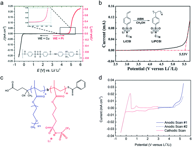 |
| | Fig. 16 Electrochemical stability window. (a) Electrochemical stability window of the corresponding blend SIC polymer electrolyte membrane (inset: chemical structure of poly(4-carboxyl benzene sulphonyl)imide). Reproduced with permission.81 Copyright 2019, Royal Society of Chemistry. (b) Linear sweep voltammetry of LiPCSI from 2.5 to 5.8 V (vs. Li/Li+) (inset: synthetic scheme of LiPCSI). Reproduced with permission.142 Copyright 2020, American Chemical Society. (c) Chemical structure of poly(PEGMA)-b-poly(LiMTFSI) copolymers. (d) Electrochemical stability window obtained by cyclic voltammetry for poly(PEGMA)-b-poly(LiMTFSI) copolymers. (c and d) are reproduced with permission.68 Copyright 2016, American Chemical Society. | |
4.4 Resistance to dendrite growth
The growth of irregular lithium plating, referred to as dendrites, is a major obstacle in the commercialization of Li-metal batteries, resulting in catastrophic failures in battery cells. Fundamentally, the mechanism of dendrite growth has remained uncovered due to the fact that lithium electrodeposition is greatly varied with time and length scales.144,145 In particular, Chazlviel and Brissot proposed space-charge theory, in which a strong concentration gradient in a symmetric cell commences Li dendrite nucleation.146,147 The concentration gradient can be given as follows:| |  | (6) |
where C and x refer to the Li salt concentration and distance from the electrode. J, D, and e correspond to the effective electrode current density, the ambipolar diffusion coefficient, and the electronic charge, respectively. μa, and μLi+ are the anion and Li+ cation mobility. When dC/dx < 2C0/L, where C0 and L indicate the initial Li salt concentration and inter-electrode distance, respectively, the ionic concentration gradient remains constant, which results in stable Li deposition. However, if dC/dx > 2C0/L, the anion concentration becomes very low in the vicinity of the anode. As a large electric field is generated from the excessive cations around the anode, the diverged potential leads to the formation of dendrites. In SIC polymer electrolytes, anion mobility is predicted to reach almost zero so that a low concentration gradient and minimal dendrite growth have been expected.
The dendrite growth suppression has been examined using either galvanostatic polarization or the morphological method. In the electrochemical approach, the symmetric Li|electrolyte|Li cells are polarized at constant current densities, and then the voltage response in the symmetric cells is monitored as the resistance change derived by dendrite growth induces a significant voltage drop. Nguyen et al. synthesized a nanostructured multiblock SIC copolymer, partially fluorinated multiblock copoly(arylene ether sulfone)s with lithium perfluorosulfonimide functional groups (Fig. 17a).42 As shown in Fig. 17b (left), the overpotential of the cell involving the SIC copolymer slightly increased with increasing current and, after cycling at each current density, the potential returned to the original value, indicating good compatibility with Li electrodes. The good compatibility with Li electrodes was further confirmed by long-term cycling tests (Fig. 17b (right)). Deng et al. prepared a SIC polymer membrane by facile coupling of LiBAMB, PETMP, and 3,6-dioxa-1,8-octanedithiol (DODT) in an electrospun PVDF supporting membrane via a one-step photoinitiated in situ thiol–ene click reaction (Fig. 17c).90 The resistance to lithium dendrite growth was shown by the galvanostatic Li plating/stripping cycling test and analysis of the morphology of Li metal electrode surface after cycling test. The Li|electrolyte|Li symmetric cell maintains an extremely stable and low overpotential without short-circuiting over a 1050 h cycle at a density of 0.5 mA cm−2 (Fig. 17d). Furthermore, the Li electrode shows a very smooth and dense surface morphology after the Li plating/stripping cycling test (Fig. 17e). Such an outstanding resistance to dendrite growth has been universally found in many SIC polymer studies.42,80,85,90,117,148–156
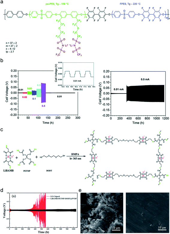 |
| | Fig. 17 Resistance to dendrite growth. (a) Molecular architecture of the SIC multi-block copolymer. (b) Galvanostatic cycling of a symmetric Li|copolymer|Li cell at different current densities (left), and its long-term cycling test at 0.5 mA (right). (a and b) are reproduced with permission.42 Copyright 2018, Royal Society of Chemistry. (c) Schematics of the synthetic process and structure of SIC LiBAMB-PETMP-DODT@PVDF polymer electrolytes. (d) Galvanostatic lithium plating/stripping cycling of a symmetric cell at a current density of 0.5 mA cm−2. (e) Scanning electron microscope images of the Li electrode surface from a Celgard cell (left) and LiBAMB-PETMP-DODT@PVDF cell (right) after the Li plating/stripping cycling test. (c–e) are reproduced with permission.90 Copyright 2018, Wiley. | |
4.5 Battery results
The practical performance of a SIC polymer electrolyte in a battery prototype has been investigated in terms of battery cycling and the retention rate of discharge capacity, which are summarized in Table 3. Exceptional properties, such as long cyclability and a high retention, rate are attributed in large part to the high ion selectivity in conduction in tandem with moderate ionic conductivity of SIC polymer electrolytes, which minimizes the concentration gradient in the cells. Chen et al. used poly(ethylene-co-vinyl alcohol) (EVOH) as the backbone and grafted with lithium 3-chloropropanesulfonyl(trifluoromethanesulfonyl)imide (LiCPSI) to synthesize the SIC polymer (EVOH-graft-LiCPSI).157 A LiFePO4/Li half-cell integrating a SIC polymer electrolyte was tested at room temperature. Fig. 18a presents the battery performances at different discharge rates from 0.2C to 5C. The LiFePO4/Li cell delivers a decreasing discharge capacity from 123 mA h g−1 at 0.2C to 92 mA h g−1 at 2C. Even at higher current rates, it still exhibits a high capacity of 72 mA h g−1 at 5C. The coulombic efficiency at each C rate is close to 100%. Fig. 18b shows the long-term cycle performance at 1C, after 500 cycles, and the discharge capacity still remains at 95 mA h g−1, suggesting a 95% retention of the initial discharge capacity. Similarly, Deng et al. synthesized SICPEs by coupling of LiBAMB and PETMP via an in situ thiol–ene click reaction in plasticizers.158 The cells showed excellent rate capability at room temperature (Fig. 18c). At a 0.2C rate, it delivered an extremely high capacity of 155 mA h g−1. Even at a high rate of 5C, it maintained a steady capacity of 86 mA h g−1. A capacity of 124 mA h g−1 was maintained after 500 cycles at a 1C rate, exhibiting long-term cycle stability with a capacity retention of 91.2% (Fig. 18d).
Table 3 Overview of various SICPEs applied in different types of batteriesa
| Battery electrodes (anode|cathode) |
Electrolyte |
C-rate |
Specific capacity (mAh g-1) |
Cycle life |
Retention rate (%) |
Ref. |
|
LiPSTFSI + VIPS/PEO: poly-lithium (4-styrenesulfonyl) (trifluoromethanesulfonyl)imide + poly 3 – (1-vinyl-3-imidazolio)propanesulfonate/poly(ethylene oxide); LiBFSIE: (lithium bis(allylmalonato) borate)-pentaerythritol tetrakis(2-mercaptoacetate); Li-PVFM: lithiated polyvinyl formal; PDMS-poly(STF-Li+-r-PEGMA)20-PDMS10: poly(dimethylsiloxane)-poly[lithium(4-styrenesulfonyl) (trifluoromethane-sulfonyl) imide-poly(ethylene glycol) methacrylate]; ANP-5: lithium tetrakis(4-(chloromethyl)-2,3,5,6-tetrafluorophenyl)borate network; PSMA-g-LiATFSI:poly(styrene-co-maleic anhydride)-g-lithium 4-aminophenylsulfonyl(trifluoromethylsulfonyl)imide; PLiSTFSI–PEGM–PEGDMA: polymerized lithium 4-styrenesulfonyl(trifluoromethylsulfonyl)imide-poly(ethylene glycol) methyl ether methacrylate-poly(ethylene glycol) dimethacrylate; NMC532: Li(Ni0.5Mn0.3Co0.2)O2; Al-FTEG: aluminium-1H,1H,11H,11H-perfluoro-3,6,9-trioxaundecane-1,11-diol; NMC111: LiNi1/3Mn1/3Co1/3O2; fluorinated polysulfonamide based SIC: polymer with –C(CF3)2 functional groups blended with poly(vinylidene fluoride-co-hexafluoropropylene); multiblock copoly(arylene ether sulfone): fluorinated multi-block copoly(arylene ether sulfone)s bearing lithium perfluorosulfonimide functions; Li-Nafion: Li-Nafion (tetrafluoroethylene-perfluoro-3,6-dioxa-4-methyl-7-octenesulfonic acid copolymer); PEMA-graft-LiATFSI: poly(ethylene-alt-maleic anhydride)-graft-lithium 4-aminophenylsulfonyl(trifluoromethylsulfonyl)imide (LiATFSI).
|
| Li|LiFePO4 |
LiPSTFSI + VIPS/PEO |
0.1C |
120.8 |
>50 |
>95 |
113
|
| LiBFSIE |
1C |
133 |
>400 |
83 |
117
|
| Li-PVFM |
0.1C |
136 |
>40 |
88 |
169
|
| PDMS-poly(STF-Li+-r-PEGMA)20-PDMS10 |
0.1C |
135 |
>100 |
91 |
170
|
| ANP-5 |
0.5C |
122 |
>100 |
99 |
70
|
| PSMA-g-LiATFSI |
1C |
130 |
>1000 |
92 |
171
|
| PLiSTFSI–PEGM–PEGDMA |
0.2C |
153 |
>100 |
92 |
91
|
| Li|NMC532 |
Al-FTEG |
0.5C |
150 |
>160 |
85 |
69
|
| Li|NMC111 |
Fluorinated polysulfonamide based SIC |
0.1C |
116 |
>100 |
84 |
81
|
| Multiblock copoly(arylene ether sulfone) |
0.2C |
100 |
>230 |
>95 |
42
|
| Li|S |
Li-Nafion |
1C |
796.6 |
>100 |
89 |
161
|
| PEMA-graft-LiATFSI |
1C |
909 |
>1000 |
85 |
162
|
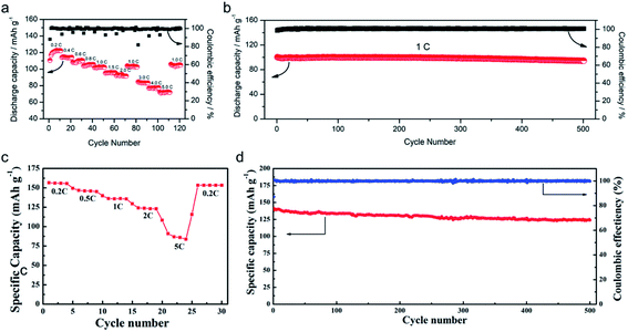 |
| | Fig. 18 Practical performances in battery prototypes. (a) Energy capacity of the LiFePO4|EVOH-graft-LiCPSI electrolyte|Li cell at room temperature over many charge/discharge cycles at various C rates. (b) Long term stability at 1C for 500 cycles. (a and b) are reproduced with permission.157 Copyright 2018, Royal Society of Chemistry. (c) Rate capability of Li|LiBAMB-PETMP/GBL|LiFePO4 cells. (d) Cycle performance at 1C. (c and d) are reproduced with permission.158 Copyright 2017, Elsevier. | |
Meanwhile, the lithium–sulfur battery is one of the most promising battery technologies owing to its highest theoretical energy density of 2600 W h kg−1 and the abundance of raw materials.159 Nevertheless, the practical applications of Li–S batteries have been severely limited by their fast self-discharge, short lifespan, and low coulombic efficiency caused by the dissolution and diffusion of reduction intermediates.160 It is crucial to suppress the diffusion of polysulfides for high-performance Li–S batteries, and SIC polymer electrolytes can potentially address the issues due to their high selectivity in ion conduction. Gao et al. employed a lithiated Nafion membrane swollen with PC (PC–Li-Nafion) as both the solid-state electrolyte and separator in solid-state Li–S cells.161 As shown in Fig. 19a, the rate capabilities for the Li–S cells were optimized by increasing the amount of Li-Nafion resin to 40% in the cathode, which can be explained by the balance between the ionic and electronic conductivities in the cathode. Due to the better interfacial contact, the specific capacity reached 895.3 mA h g−1 at 1C. As for the cycling performance of the Li–S cell, a good capacity retention of 89% after 100 cycles at a 1C rate can be achieved at 70 °C (Fig. 19b). Li et al. used lithium 4-aminophenylsulfonyl(trifluoromethylsulfonyl)imide (LiATFSI) grafted with poly(ethylene-alt-maleic anhydride) (PEMA) to fabricate a SIC (PEMA-graft-LiATFSI) polymer electrolyte.162 The electrolyte membrane showed an ionic conductivity of 0.216 mS cm−1 and a high lithium transference number of 0.94 at 25 °C. Therefore, the Li–S battery prototype exhibited excellent rate capacity (Fig. 19c). In the cycling test, the discharge capacity can be maintained at 780.8 mA h g−1 at 1C even after 1000 cycles (Fig. 19d), compared with a capacity of 443.3 mA h g−1 for its counterpart.
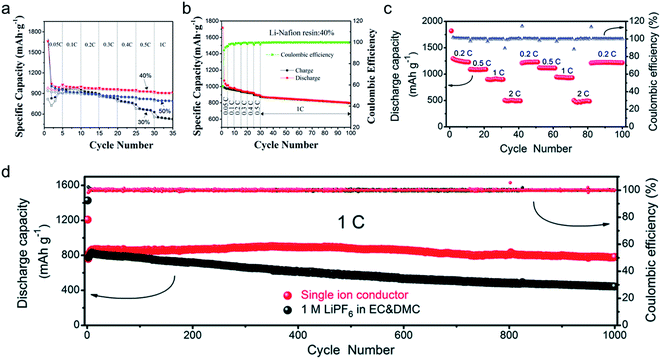 |
| | Fig. 19 Performance in Li–S batteries. The rate performance (a) and the cycling behavior (b) of the Li|PC-Li-Nafion membrane|C–S cells. (a and b) are reproduced with permission.161 Copyright 2017, Elsevier. (c) Rate performance of Li|PEMA-graft-LiATFSI|S@PAN cells at various C rates and (d) cycling performances at 1C for 1000 cycles. (c and d) are reproduced with permission.162 Copyright 2018, Royal Society of Chemistry. | |
5. Conclusion and perspective
As demonstrated by Bolloré, solid-state batteries featuring polymer electrolytes are poised to dominate the next-generation battery market for achieving long range, fast charging, and affordable EVs. The formidable challenges, such as low ion selectivity in conduction, high cell polarization, and significant safety hazards caused by dendrite growth, of conventional polymer electrolytes have induced a conceptual shift away from binary-ion conducting polymers toward SIC polymers. Ever since the development of ion-selective polymers in 1984, SIC polymers have been made of varying building blocks, such as anionic groups (carboxylate, sulfonate, sulfonylimide, and borate groups), polymer matrices (linear, branched, and network polymers), and anion trapping macromolecules. Several fabrication techniques, including casting, phase-separation, in situ polymerization, and electrospinning, have been employed to form a membrane for the integration of a SIC polymer electrolyte into battery cells. To date, regardless of SIC types, SIC polymer electrolytes have demonstrated a decent ionic conductivity ranging from 10−6 to 10−3 S cm−1, exceptional selectivity for Li+ cation conduction, a wide electrochemical window, and dendrite growth resistance. Significantly, battery prototypes containing a SIC polymer electrolyte are shown to outperform a conventional battery featuring polymer electrolytes in terms of rate capability.
Although many efforts have been dedicated to boosting the performance of SIC polymer electrolytes, the ionic conductivity at room temperature and below is still unsatisfactory for their practical applications. Furthermore, the interfacial contact between the SIC polymer and electrodes during charging/discharging has remained to be addressed for a longer cycle life. On the basis of our understanding, future research needs to pay attention to improving these properties as follows:
(1) Weakening the affinity to Li+ cations has been found to significantly facilitate ionic transport in the SIC polymer electrolyte, and indeed the negative charge delocalization by electron-withdrawing groups promotes ionic transport at ambient temperature. In addition, SIC polymer electrolytes possessing weakly coordinating anions, such as sulfonylimide and borate groups, have been shown to reach a high ionic conductivity of 10−4 S cm−1. In this sense, the implementation of other weakly coordinating anions, e.g. aluminate anions (Al(OC(CF3)3)4−), phosphate anions (PF6−), and chlorate anions (ClO4−), with less binding affinity to Li+ cations might be a promising route to further improve the ionic conductivity. For example, the aluminate anion, Al(OC(CF3)3)4−, has been found to isolate highly reactive cationic species, indicating that it possesses a weaker binding affinity compared to tetrakis(pentafluorophenyl)borate, B(C6F5)4−.163
(2) The short distance between anionic centers has been predicted to be a critical factor for efficient site-to-site Li+ cation hopping,20,51 but there has usually been a trade-off between sufficient proximity and polymer flexibility. Therefore, the key and challenging design routes in future are lowering the distance of Li+ cation hopping, while maintaining the segmental motion of polymer chains for Li+ cation solvation/desolvation. A fractal structure might be very effective for promoting polymer flexibility without increasing the anionic center distance. A network polymer matrix may prove to be a good platform to achieve both proximity and high polymer flexibility due to its interpenetration structure.51,70
(3) During lithiation and delithiation, all active electrode materials undergo volume changes. The intercalation electrodes such as graphite and cathodes exhibit a volumetric strain of <13% upon full lithiation,164 and the volumetric change can reach up to 400% (ref. 165) and is infinite3 for silicon and Li metal electrodes, respectively. In particular, Li metal is predicted to experience a thickness change of tens of micrometers,3 causing severe damage to the interface between the solid electrolyte and electrodes. Given that the adhesion feature has been found to decrease dramatically when the shear modulus exceeds a few MPa,166,167 the softness and elasticity of the SIC polymer electrolyte must be considered to maintain a direct contact with electrodes.
We anticipate that all these efforts will speed up the boosting of the requisite properties of SIC polymer electrolytes for battery operation, and the integration of SIC polymer electrolytes shows promise for commercial all-solid-state batteries in the near future.
Author contributions
J. G., C. W., and D. M. S. formulated the project, and J. G., C. W., D. W. H., and D. M. S. conducted literature review. J. G., C. W., and D. M. S. wrote the manuscript, and all authors contributed to revising the manuscript.
Conflicts of interest
The authors declare that they have no known competing financial interests or personal relationships that could have appeared to influence the work reported in this paper.
Acknowledgements
We acknowledge the financial support of the Environment and Conservation Fund of the Hong Kong Special Administrative Region, China, under Award Number ECF 100/2019. Additionally, this work was supported by the Seed and Startup Fund, funded by the Department of Mechanical Engineering and Faculty of Engineering at the University of Hong Kong (201904185007).
References
- J. W. Choi and D. Aurbach, Nat. Rev. Mater., 2016, 1, 16013 CrossRef CAS.
- J. B. Goodenough and Y. Kim, Chem. Mater., 2010, 22, 587–603 CrossRef CAS.
- D. Lin, Y. Liu and Y. Cui, Nat. Nanotechnol., 2017, 12, 194–206 CrossRef CAS.
- Y. Lu, Z. Tu and L. A. Archer, Nat. Mater., 2014, 13, 961–969 CrossRef CAS PubMed.
- E. M. Erickson, E. Markevich, G. Salitra, D. Sharon, D. Hirshberg, E. de la Llave, I. Shterenberg, A. Rosenman, A. Frimer and D. Aurbach, J. Electrochem. Soc., 2015, 162, A2424–A2438 CrossRef CAS.
- L. Long, S. Wang, M. Xiao and Y. Meng, J. Mater. Chem. A, 2016, 4, 10038–10069 RSC.
- R. Bouchet, S. Maria, R. Meziane, A. Aboulaich, L. Lienafa, J. P. Bonnet, T. N. T. Phan, D. Bertin, D. Gigmes, D. Devaux, R. Denoyel and M. Armand, Nat. Mater., 2013, 12, 452–457 CrossRef CAS.
- D. J. Bannister, G. R. Davies, I. M. Ward and J. E. McIntyre, Polymer, 1984, 25, 1291–1296 CrossRef CAS.
- M. Doyle, T. F. Fuller and J. Newman, Electrochim. Acta, 1994, 39, 2073–2081 CrossRef CAS.
- M. Doyle and J. Newman, Electrochim. Acta, 1995, 40, 2191–2196 CrossRef CAS.
- K. E. Thomas, S. E. Sloop, J. B. Kerr and J. Newman, J. Power Sources, 2000, 89, 132–138 CrossRef CAS.
- C. Brissot, M. Rosso, J. N. Chazalviel and S. Lascaud, J. Power Sources, 1999, 81–82, 925–929 CrossRef CAS.
- M. Rosso, C. Brissot, A. Teyssot, M. Dollé, L. Sannier, J.-M. Tarascon, R. Bouchet and S. Lascaud, Electrochim. Acta, 2006, 51, 5334–5340 CrossRef CAS.
- H. Zhang, C. Li, M. Piszcz, E. Coya, T. Rojo, L. M. Rodriguez-Martinez, M. Armand and Z. Zhou, Chem. Soc. Rev., 2017, 46, 797–815 RSC.
- K. Deng, Q. Zeng, D. Wang, Z. Liu, Z. Qiu, Y. Zhang, M. Xiao and Y. Meng, J. Mater. Chem. A, 2020, 8, 1557–1577 RSC.
- K. Jeong, S. Park and S. Y. Lee, J. Mater. Chem. A, 2019, 7, 1917–1935 RSC.
- J. Zhu, Z. Zhang, S. Zhao, A. S. Westover, I. Belharouak and P. F. Cao, Adv. Energy Mater., 2021, 11, 2003836 CrossRef CAS.
- D. Benrabah, S. Sylla, J. Y. Sanchez and M. Armand, J. Power Sources, 1995, 54, 456–460 CrossRef CAS.
- D. Benrabah, S. Sylla, F. Alloin, J. Y. Sanchez and M. Armand, Electrochim. Acta, 1995, 40, 2259–2264 CrossRef CAS.
- K. J. Lin, K. Li and J. K. Maranas, RSC Adv., 2013, 3, 1564–1571 RSC.
- Z. F. Kanyo and D. W. Christianson, J. Biol. Chem., 1991, 266, 4264–4268 CrossRef CAS.
- M. Egli, Chem. Biol., 2002, 9, 277–286 CrossRef CAS.
-
B. Casu and U. Lindahl, in Advances in Carbohydrate Chemistry and Biochemistry, Academic Press, 2001, vol. 57, pp. 159–206 Search PubMed.
- E. Tsuchida, H. Ohno, N. Kobayashi and H. Ishizaka, Macromolecules, 1989, 22, 1771–1775 CrossRef CAS.
- X. Huang, L. Chen, H. Huang, R. Xue, Y. Ma, S. Fang, Y. Li and Y. Jiang, Solid State Ionics, 1992, 51, 69–73 CrossRef CAS.
- H. T. Kim and J.-K. Park, Solid State Ionics, 1997, 98, 237–244 CrossRef CAS.
- J. Rolland, E. Poggi, A. Vlad and J.-F. Gohy, Polymer, 2015, 68, 344–352 CrossRef CAS.
- M. Zhang, S. Yu, Y. Mai, S. Zhang and Y. Zhou, Chem. Commun., 2019, 55, 6715–6718 RSC.
- M. Remko, P. T. Van Duijnen and C.-W. von der Lieth, J. Mol. Struct.: THEOCHEM, 2007, 814, 119–125 CrossRef CAS.
- A. Razmjou, M. Asadnia, E. Hosseini, A. Habibnejad Korayem and V. Chen, Nat. Commun., 2019, 10, 5793 CrossRef CAS PubMed.
- S. Zhang, Z. Deng and G. Wan, Polym. J., 1991, 23, 73–78 CrossRef CAS.
- C. H. Park, Y. K. Sun and D. W. Kim, Electrochim. Acta, 2004, 50, 375–378 CrossRef CAS.
- P.-Y. Ji, J. Fang, Y.-Y. Zhang, P. Zhang and J.-B. Zhao, ChemElectroChem, 2017, 4, 2352–2358 CrossRef CAS.
- M. V. O'Reilly, H. Masser, D. R. King, P. C. Painter, R. H. Colby, K. I. Winey and J. Runt, Polymer, 2015, 59, 133–143 CrossRef.
- J. M. G. Cowie and G. H. Spence, Solid State Ionics, 1999, 123, 233–242 CrossRef CAS.
- Z. Shao and P. Jannasch, Polym. Chem., 2017, 8, 785–794 RSC.
- D. D. Desmarteau and M. Witz, J. Fluorine Chem., 1991, 52, 7–12 CrossRef CAS.
- S. Antoniotti, V. Dalla and E. Duñach, Angew. Chem., Int. Ed. Engl., 2010, 49, 7860–7888 CrossRef CAS PubMed.
- J. Foropoulos and D. D. DesMarteau, Inorg. Chem., 1984, 23, 3720–3723 CrossRef CAS.
- M. B. Armand, Annu. Rev. Mater. Sci., 1986, 16, 245–261 CrossRef CAS.
- W. Zhang, S. Feng, M. Huang, B. Qiao, K. Shigenobu, L. Giordano, J. Lopez, R. Tatara, K. Ueno, K. Dokko, M. Watanabe, Y. Shao-Horn and J. A. Johnson, Chem. Mater., 2021, 33, 524–534 CrossRef CAS.
- H. D. Nguyen, G.-T. Kim, J. Shi, E. Paillard, P. Judeinstein, S. Lyonnard, D. Bresser and C. Iojoiu, Energy Environ. Sci., 2018, 11, 3298–3309 RSC.
- R. Rohan, Y. Sun, W. Cai, Y. Zhang, K. Pareek, G. Xu and H. Cheng, Solid State Ionics, 2014, 268, 294–299 CrossRef CAS.
- C. Cao, Y. Li, Y. Feng, P. Long, H. An, C. Qin, J. Han, S. Li and W. Feng, J. Mater. Chem. A, 2017, 5, 22519–22526 RSC.
- M. Finze, E. Bernhardt and H. Willner, Angew. Chem., Int. Ed. Engl., 2007, 46, 9180–9196 CrossRef CAS.
- I. M. Riddlestone, A. Kraft, J. Schaefer and I. Krossing, Angew. Chem., Int. Ed. Engl., 2018, 57, 13982–14024 CrossRef CAS.
- X.-G. Sun, C. L. Reeder and J. B. Kerr, Macromolecules, 2004, 37, 2219–2227 CrossRef CAS.
- Y. S. Zhu, X. J. Wang, Y. Y. Hou, X. W. Gao, L. L. Liu, Y. P. Wu and M. Shimizu, Electrochim. Acta, 2013, 87, 113–118 CrossRef CAS.
- G. Xu, Y. Zhang, R. Rohan, W. Cai and H. Cheng, Electrochim. Acta, 2014, 139, 264–269 CrossRef CAS.
- S. Liang, U. H. Choi, W. Liu, J. Runt and R. H. Colby, Chem. Mater., 2012, 24, 2316–2323 CrossRef CAS.
- J. F. Van Humbeck, M. L. Aubrey, A. Alsbaiee, R. Ameloot, G. W. Coates, W. R. Dichtel and J. R. Long, Chem. Sci., 2015, 6, 5499–5505 RSC.
- Q. Ma, H. Zhang, C. Zhou, L. Zheng, P. Cheng, J. Nie, W. Feng, Y. S. Hu, H. Li, X. Huang, L. Chen, M. Armand and Z. Zhou, Angew. Chem., Int. Ed. Engl., 2016, 55, 2521–2525 CrossRef CAS PubMed.
- G. Mao, R. F. Perea, W. S. Howells, D. L. Price and M.-L. Saboungi, Nature, 2000, 405, 163–165 CrossRef CAS PubMed.
- S. B. Aziz, T. J. Woo, M. F. Z. Kadir and H. M. Ahmed, J. Sci.: Adv. Mater. Devices, 2018, 3, 1–17 Search PubMed.
- J. Siva Kumar, A. R. Subrahmanyam, M. Jaipal Reddy and U. V. Subba Rao, Mater. Lett., 2006, 60, 3346–3349 CrossRef.
-
Handbook of Solid State Batteries and Capacitors, ed. M. Z. A. Munshi, World Scientific, 1995 Search PubMed.
-
M. Aguilar-Vega, in Handbook of Polymer Synthesis, Characterization, and Processing, 2013, pp. 425–434 Search PubMed.
-
J. E. Mark, in Silicones and Silicone-Modified Materials, American Chemical Society, 2000, vol. 729, ch. 1, pp. 1–10 Search PubMed.
- K. Nagaoka, H. Naruse, I. Shinohara and M. Watanabe, J. Polym. Sci., Polym. Lett. Ed., 1984, 22, 659–663 CrossRef CAS.
- L. Zhang, Z. Zhang, S. Harring, M. Straughan, R. Butorac, Z. Chen, L. Lyons, K. Amine and R. West, J. Mater. Chem., 2008, 18, 3713–3717 RSC.
- N. Meng, F. Lian and G. Cui, Small, 2021, 17, 2005762 CrossRef CAS.
- J. Lopez, D. G. Mackanic, Y. Cui and Z. Bao, Nat. Rev. Mater., 2019, 4, 312–330 CrossRef CAS.
- J. Sun, G. M. Stone, N. P. Balsara and R. N. Zuckermann, Macromolecules, 2012, 45, 5151–5156 CrossRef CAS.
- C. M. Bates, A. B. Chang, N. Momčilović, S. C. Jones and R. H. Grubbs, Macromolecules, 2015, 48, 4967–4973 CrossRef CAS.
- S. Feng, D. Shi, F. Liu, L. Zheng, J. Nie, W. Feng, X. Huang, M. Armand and Z. Zhou, Electrochim. Acta, 2013, 93, 254–263 CrossRef CAS.
- Y. Ding, X. Shen, J. Zeng, X. Wang, L. Peng, P. Zhang and J. Zhao, Solid State Ionics, 2018, 323, 16–24 CrossRef CAS.
- A. S. Shaplov, R. Marcilla and D. Mecerreyes, Electrochim. Acta, 2015, 175, 18–34 CrossRef CAS.
- L. Porcarelli, A. S. Shaplov, M. Salsamendi, J. R. Nair, Y. S. Vygodskii, D. Mecerreyes and C. Gerbaldi, ACS Appl. Mater. Interfaces, 2016, 8, 10350–10359 CrossRef CAS PubMed.
- Z. Yu, D. G. Mackanic, W. Michaels, M. Lee, A. Pei, D. Feng, Q. Zhang, Y. Tsao, C. V. Amanchukwu, X. Yan, H. Wang, S. Chen, K. Liu, J. Kang, J. Qin, Y. Cui and Z. Bao, Joule, 2019, 3, 2761–2776 CrossRef CAS.
- D.-M. Shin, J. E. Bachman, M. K. Taylor, J. Kamcev, J. G. Park, M. E. Ziebel, E. Velasquez, N. N. Jarenwattananon, G. K. Sethi, Y. Cui and J. R. Long, Adv. Mater., 2020, 32, 1905771 CrossRef CAS.
- M. L. Aubrey, J. C. Axelson, K. E. Engler and J. R. Long, Macromolecules, 2021, 54(16), 7582–7589 CrossRef CAS.
- H. Gan, Y. Zhang, S. Li, L. Yu, J. Wang and Z. Xue, ACS Appl. Energy Mater., 2021, 4, 482–491 CrossRef CAS.
- M. A. Mehta, T. Fujinami and T. Inoue, J. Power Sources, 1999, 81–82, 724–728 CrossRef CAS.
- A. M. Stephan, T. Prem Kumar, N. Angulakshmi, P. S. Salini, R. Sabarinathan, A. Srinivasan and S. Thomas, J. Appl. Polym. Sci., 2011, 120, 2215–2221 CrossRef CAS.
- D. P. Siska and D. F. Shriver, Chem. Mater., 2001, 13, 4698–4700 CrossRef CAS.
- T. Fujinami, M. A. Mehta, K. Sugie and K. Mori, Electrochim. Acta, 2000, 45, 1181–1186 CrossRef CAS.
- M. Meyer, C. Vechambre, L. Viau, A. Mehdi, O. Fontaine, E. Mourad, S. Monge, J.-M. Chenal, L. Chazeau and A. Vioux, J. Mater. Chem. A, 2014, 2, 12162–12165 RSC.
- H. Zhao, Z. Jia, W. Yuan, H. Hu, Y. Fu, G. L. Baker and G. Liu, ACS Appl. Mater. Interfaces, 2015, 7, 19335–19341 CrossRef CAS.
- N. Lago, O. Garcia-Calvo, J. M. Lopez del Amo, T. Rojo and M. Armand, ChemSusChem, 2015, 8, 3039–3043 CrossRef CAS PubMed.
- Y. Zhang, J. Wang, C. Tan, Y. He, Y. Chen, S. Huo, D. Zeng, C. Li and H. Cheng, J. Membr. Sci., 2021, 620, 118921 CrossRef CAS.
- K. Borzutzki, J. Thienenkamp, M. Diehl, M. Winter and G. Brunklaus, J. Mater. Chem. A, 2019, 7, 188–201 RSC.
- X. Wang, Z. Liu, Q. Kong, W. Jiang, J. Yao, C. Zhang and G. Cui, Solid State Ionics, 2014, 262, 747–753 CrossRef CAS.
- Y. Chen, Z. Li, X. Liu, D. Zeng, Y. Zhang, Y. Sun, H. Ke and H. Cheng, J. Membr. Sci., 2017, 544, 47–57 CrossRef CAS.
- Z. H. Li, H. P. Zhang, P. Zhang, G. C. Li, Y. P. Wu and X. D. Zhou, J. Membr. Sci., 2008, 322, 416–422 CrossRef CAS.
- H. Oh, K. Xu, H. D. Yoo, D. S. Kim, C. Chanthad, G. Yang, J. Jin, I. A. Ayhan, S. M. Oh and Q. Wang, Chem. Mater., 2016, 28, 188–196 CrossRef CAS.
- S. Liang, W. Yan, X. Wu, Y. Zhang, Y. Zhu, H. Wang and Y. Wu, Solid State Ionics, 2018, 318, 2–18 CrossRef CAS.
- B. S. Lalia, V. Kochkodan, R. Hashaikeh and N. Hilal, Desalination, 2013, 326, 77–95 CrossRef CAS.
- N. Liang, J. Fang and X. Guo, J. Mater. Chem. A, 2017, 5, 15087–15095 RSC.
- L. Porcarelli, A. S. Shaplov, F. Bella, J. R. Nair, D. Mecerreyes and C. Gerbaldi, ACS Energy Lett, 2016, 1, 678–682 CrossRef CAS.
- K. Deng, J. Qin, S. Wang, S. Ren, D. Han, M. Xiao and Y. Meng, Small, 2018, 14, 1801420 CrossRef PubMed.
- G. Luo, B. Yuan, T. Guan, F. Cheng, W. Zhang and J. Chen, ACS Appl. Energy Mater., 2019, 2, 3028–3034 CrossRef CAS.
- Y. Kim, S. J. Kwon, H.-k. Jang, B. M. Jung, S. B. Lee and U. H. Choi, Chem. Mater., 2017, 29, 4401–4410 CrossRef CAS.
- S.-K. Kim, D.-G. Kim, A. Lee, H.-S. Sohn, J. J. Wie, N. A. Nguyen, M. E. Mackay and J. C. Lee, Macromolecules, 2012, 45, 9347–9356 CrossRef CAS.
- K. Liu, S. Jiang, T. L. Dzwiniel, H.-K. Kim, Z. Yu, N. L. Dietz Rago, J. J. Kim, T. T. Fister, J. Yang, Q. Liu, J. Gilbert, L. Cheng, V. Srinivasan, Z. Zhang and C. Liao, ACS Appl. Mater. Interfaces, 2020, 12, 29162–29172 CAS.
- B.-Y. Hsieh, J. Kim, J. Zhu, S. Li, X. Zhang and X. Jiang, Appl. Phys. Lett., 2015, 106, 021902 CrossRef.
- R. Rohan, T.-C. Kuo, M.-W. Chen and J.-T. Lee, ChemElectroChem, 2017, 4, 2178–2183 CrossRef CAS.
- Y. Kato, S. Hori, T. Saito, K. Suzuki, M. Hirayama, A. Mitsui, M. Yonemura, H. Iba and R. Kanno, Nat. Energy, 2016, 1, 16030 CrossRef CAS.
- L. R. A. K. Bandara, M. A. K. L. Dissanayake and B. E. Mellander, Electrochim. Acta, 1998, 43, 1447–1451 CrossRef CAS.
- X. Zhang, S. Wang, C. Xue, C. Xin, Y. Lin, Y. Shen, L. Li and C.-W. Nan, Adv. Mater., 2019, 31, 1806082 CrossRef PubMed.
- X. Zhang, S. Wang, C. Xue, C. Xin, Y. Lin, Y. Shen, L. Li and C.-W. Nan, Adv. Mater., 2020, 32, 2000026 CrossRef CAS.
- J. M. Tarascon, A. S. Gozdz, C. Schmutz, F. Shokoohi and P. C. Warren, Solid State Ionics, 1996, 86–88, 49–54 CrossRef CAS.
- M. Wetjen, G.-T. Kim, M. Joost, M. Winter and S. Passerini, Electrochim. Acta, 2013, 87, 779–787 CrossRef CAS.
- S. Zhang, J. Zhang, Y. Zhang and Y. Deng, Chem. Rev., 2017, 117, 6755–6833 CrossRef CAS PubMed.
- L. Porcarelli, P. S. Vlasov, D. O. Ponkratov, E. I. Lozinskaya, D. Y. Antonov, J. R. Nair, C. Gerbaldi, D. Mecerreyes and A. S. Shaplov, Eur. Polym. J., 2018, 107, 218–228 CrossRef CAS.
- N. A. Stolwijk and S. Obeidi, Phys. Rev. Lett., 2004, 93, 125901 CrossRef CAS PubMed.
- H. G. Buss, S. Y. Chan, N. A. Lynd and B. D. McCloskey, ACS Energy Lett, 2017, 2, 481–487 CrossRef CAS.
- K. S. Cole and R. H. Cole, J. Chem. Phys., 1941, 9, 341–351 CrossRef.
- P. Colomban and A. Novak, J. Mol. Struct., 1988, 177, 277–308 CrossRef.
- R. G. Linford and S. Hackwood, Chem. Rev., 1981, 81, 327–364 CrossRef.
- N. Kamaya, K. Homma, Y. Yamakawa, M. Hirayama, R. Kanno, M. Yonemura, T. Kamiyama, Y. Kato, S. Hama, K. Kawamoto and A. Mitsui, Nat. Mater., 2011, 10, 682–686 CrossRef PubMed.
- G. Tammann and W. Hesse, Z. Anorg. Allg. Chem., 1926, 156, 245–257 CrossRef CAS.
- G. S. Fulcher, J. Am. Ceram. Soc., 1925, 8, 339–355 CrossRef CAS.
- F. Lu, G. Li, Y. Yu, X. Gao, L. Zheng and Z. Chen, Chem. Eng. J., 2020, 384, 123237 CrossRef CAS.
- E. R. Nightingale, J. Phys. Chem., 1959, 63, 1381–1387 CrossRef CAS.
- U. H. Choi, S. Liang, M. V. O'Reilly, K. I. Winey, J. Runt and R. H. Colby, Macromolecules, 2014, 47, 3145–3153 CrossRef CAS.
- S. Das and A. Ghosh, Electrochim. Acta, 2015, 171, 59–65 CrossRef CAS.
- J. Zhang, S. Wang, D. Han, M. Xiao, L. Sun and Y. Meng, Energy Storage Materials, 2020, 24, 579–587 CrossRef.
- Z. Xue, D. He and X. Xie, J. Mater. Chem. A, 2015, 3, 19218–19253 RSC.
- X. Cheng, J. Pan, Y. Zhao, M. Liao and H. Peng, Adv. Energy Mater., 2018, 8, 1702184 CrossRef.
- X. Wang, H. Zhu, G. M. A. Girard, R. Yunis, D. R. MacFarlane, D. Mecerreyes, A. J. Bhattacharyya, P. C. Howlett and M. Forsyth, J. Mater. Chem. A, 2017, 5, 23844–23852 RSC.
- S. Zhao, Y. Zhang, H. Pham, J.-M. Y. Carrillo, B. G. Sumpter, J. Nanda, N. J. Dudney, T. Saito, A. P. Sokolov and P.-F. Cao, ACS Appl. Energy Mater., 2020, 3, 12540–12548 CrossRef.
- C. Shen, Q. Zhao, N. Shan, B. B. Jing and C. M. Evans, J. Polym. Sci., 2020, 58, 2376–2388 CrossRef.
- R. L. Weber and M. K. Mahanthappa, Soft Matter, 2017, 13, 7633–7643 RSC.
- J. Kärger, M. Avramovska, D. Freude, J. Haase, S. Hwang and R. Valiullin, Adsorption, 2021, 27, 453–484 CrossRef.
-
L. R. F. Allen and J. Bard, Electrochemical Methods: Fundamentals and Applications, John Wiley and Sons, New York, 2nd edn, 2000 Search PubMed.
-
M. Spiro, in Physical Methods of Chemistry, ed. A. W. a. B. W. Rossiter, Wiley-Interscience, New York, 1971 Search PubMed.
- H. P. Gregor, J. Appl. Polym. Sci., 1960, 3, 255 CrossRef.
- H. Hafezi and J. Newman, J. Electrochem. Soc., 2000, 147, 3036 CrossRef CAS.
- J. Evans, C. A. Vincent and P. G. Bruce, Polymer, 1987, 28, 2324–2328 CrossRef CAS.
- S. Zugmann, M. Fleischmann, M. Amereller, R. M. Gschwind, H. D. Wiemhöfer and H. J. Gores, Electrochim. Acta, 2011, 56, 3926–3933 CrossRef CAS.
- S. Li, A. I. Mohamed, V. Pande, H. Wang, J. Cuthbert, X. Pan, H. He, Z. Wang, V. Viswanathan, J. F. Whitacre and K. Matyjaszewski, ACS Energy Lett, 2018, 3, 20–27 CrossRef CAS.
- C. Liu, Z. G. Neale and G. Cao, Mater. Today, 2016, 19, 109–123 CrossRef CAS.
- J. B. Goodenough, Acc. Chem. Res., 2013, 46, 1053–1061 CrossRef CAS PubMed.
- Q. Yang, J. Huang, Y. Li, Y. Wang, J. Qiu, J. Zhang, H. Yu, X. Yu, H. Li and L. Chen, J. Power Sources, 2018, 388, 65–70 CrossRef CAS.
- H. Duan, M. Fan, W.-P. Chen, J.-Y. Li, P.-F. Wang, W.-P. Wang, J.-L. Shi, Y.-X. Yin, L.-J. Wan and Y.-G. Guo, Adv. Mater., 2019, 31, 1807789 CrossRef PubMed.
- W. Zhou, Z. Wang, Y. Pu, Y. Li, S. Xin, X. Li, J. Chen and J. B. Goodenough, Adv. Mater., 2019, 31, 1805574 CrossRef PubMed.
- X. Yang, M. Jiang, X. Gao, D. Bao, Q. Sun, N. Holmes, H. Duan, S. Mukherjee, K. Adair, C. Zhao, J. Liang, W. Li, J. Li, Y. Liu, H. Huang, L. Zhang, S. Lu, Q. Lu, R. Li, C. V. Singh and X. Sun, Energy Environ. Sci., 2020, 13, 1318–1325 RSC.
- C. Wang, T. Wang, L. Wang, Z. Hu, Z. Cui, J. Li, S. Dong, X. Zhou and G. Cui, Adv. Sci., 2019, 6, 1901036 CrossRef PubMed.
- M. Gauthier, T. J. Carney, A. Grimaud, L. Giordano, N. Pour, H.-H. Chang, D. P. Fenning, S. F. Lux, O. Paschos, C. Bauer, F. Maglia, S. Lupart, P. Lamp and Y. Shao-Horn, J. Phys. Chem. Lett., 2015, 6, 4653–4672 CrossRef PubMed.
- J. Kalhoff, G. G. Eshetu, D. Bresser and S. Passerini, ChemSusChem, 2015, 8, 2154–2175 CrossRef PubMed.
- Y.-K. Han, Y. Moon, K. Lee and Y. S. Huh, Curr. Appl. Phys., 2014, 14, 897–900 CrossRef.
- H. Yuan, J. Luan, Z. Yang, J. Zhang, Y. Wu, Z. Lu and H. Liu, ACS Appl. Mater. Interfaces, 2020, 12, 7249–7256 CrossRef CAS PubMed.
- J. Kasnatscheew, B. Streipert, S. Röser, R. Wagner, I. Cekic Laskovic and M. Winter, Phys. Chem. Chem. Phys., 2017, 19, 16078–16086 RSC.
- P. Bai, J. Li, F. R. Brushett and M. Z. Bazant, Energy Environ. Sci., 2016, 9, 3221–3229 RSC.
- A. Jana and R. E. García, Nano Energy, 2017, 41, 552–565 CrossRef CAS.
- C. Brissot, M. Rosso, J.-N. Chazalviel and S. Lascaud, J. Power Sources, 1999, 81, 925 CrossRef.
- J. N. Chazalviel, Phys. Rev. A, 1990, 42, 7355–7367 CrossRef CAS PubMed.
- T. K. L. Nguyen, G. Lopez, C. Iojoiu, R. Bouchet and B. Ameduri, J. Power Sources, 2021, 498, 229920 CrossRef CAS.
- C. H. Krause, A. J. Butzelaar, D. Diddens, D. Dong, P. Théato, D. Bedrov, B.-J. Hwang, M. Winter and G. Brunklaus, J. Power Sources, 2021, 484, 229267 CrossRef.
- J. Zhang, Y. Zhong, S. Wang, D. Han, M. Xiao, L. Sun and Y. Meng, ACS Appl. Energy Mater., 2021, 4, 862–869 CrossRef.
- Y. Wang, L. Fu, L. Shi, Z. Wang, J. Zhu, Y. Zhao and S. Yuan, ACS Appl. Mater. Interfaces, 2019, 11, 5168–5175 CrossRef PubMed.
- Y. Li, K. W. Wong, Q. Dou and K. M. Ng, J. Mater. Chem. A, 2016, 4, 18543–18550 RSC.
- Y. Zhong, L. Zhong, S. Wang, J. Qin, D. Han, S. Ren, M. Xiao, L. Sun and Y. Meng, J. Mater. Chem. A, 2019, 7, 24251–24261 RSC.
- K.-L. Liu, C.-H. Chao, H.-C. Lee, C.-S. Tsao, J. Fang, N.-L. Wu and C.-Y. Chao, J. Power Sources, 2019, 419, 58–64 CrossRef CAS.
- Y. Zhang, M. Pan, X. Liu, C. Li, J. Dong, Y. Sun, D. Zeng, Z. Yang and H. Cheng, Energy Technol, 2018, 6, 289–295 CrossRef CAS.
- C. Li, B. Qin, Y. Zhang, A. Varzi, S. Passerini, J. Wang, J. Dong, D. Zeng, Z. Liu and H. Cheng, Adv. Energy Mater., 2019, 9, 1803422 CrossRef.
- Y. Chen, G. Xu, X. Liu, Q. Pan, Y. Zhang, D. Zeng, Y. Sun, H. Ke and H. Cheng, RSC Adv., 2018, 8, 39967–39975 RSC.
- K. Deng, S. Wang, S. Ren, D. Han, M. Xiao and Y. Meng, J. Power Sources, 2017, 360, 98–105 CrossRef CAS.
- Y.-X. Yin, S. Xin, Y.-G. Guo and L.-J. Wan, Angew. Chem., Int. Ed. Engl., 2013, 52, 13186–13200 CrossRef CAS PubMed.
- Y. Sun, G. Li, Y. Lai, D. Zeng and H. Cheng, Sci. Rep., 2016, 6, 22048 CrossRef CAS PubMed.
- J. Gao, C. Sun, L. Xu, J. Chen, C. Wang, D. Guo and H. Chen, J. Power Sources, 2018, 382, 179–189 CrossRef.
- Z. Li, W. Lu, N. Zhang, Q. Pan, Y. Chen, G. Xu, D. Zeng, Y. Zhang, W. Cai, M. Yang, Z. Yang, Y. Sun, H. Ke and H. Cheng, J. Mater. Chem. A, 2018, 6, 14330–14338 RSC.
- T. A. Engesser, C. Friedmann, A. Martens, D. Kratzert, P. J. Malinowski and I. Krossing, Chem. –Eur. J., 2016, 22, 15085–15094 CrossRef PubMed.
- R. Koerver, W. Zhang, L. de Biasi, S. Schweidler, A. O. Kondrakov, S. Kolling, T. Brezesinski, P. Hartmann, W. G. Zeier and J. Janek, Energy Environ. Sci., 2018, 11, 2142–2158 RSC.
- I. Ryu, J. W. Choi, Y. Cui and W. D. Nix, J. Mech. Phys. Solids, 2011, 59, 1717–1730 CrossRef CAS.
- P. Weiss, J. Appl. Polym. Sci., 1969, 13, 1326 CrossRef.
- C. Creton and L. Leibler, J. Polym. Sci., Part B: Polym. Phys., 1996, 34, 545–554 CrossRef CAS.
- L. Porcarelli, M. A. Aboudzadeh, L. Rubatat, J. R. Nair, A. S. Shaplov, C. Gerbaldi and D. Mecerreyes, J. Power Sources, 2017, 364, 191–199 CrossRef CAS.
- H. Zhang, F. Lian, L. Bai, N. Meng and C. Xu, J. Membr. Sci., 2018, 552, 349–356 CrossRef CAS.
- P. Cao, B. Li, G. Yang, S. Zhao, J. Townsend, K. Xing, Z. Qiang, K. D. Vogiatzis, A. P. Sokolov, J. Nanda and T. Saito, Macromolecules, 2020, 53, 3591–3601 CrossRef CAS.
- D. Du, X. Hu, D. Zeng, Y. Zhang, Y. Sun, J. Li and H. Cheng, ACS Appl. Energy Mater., 2020, 3, 1128–1138 CrossRef CAS.
Footnote |
| † J. G. and C. W. contributed equally to this work. |
|
| This journal is © The Royal Society of Chemistry 2021 |
Click here to see how this site uses Cookies. View our privacy policy here.  Open Access Article
 a,
Cong
Wang†
 a,
Dong-Wook
Han
 b and
Dong-Myeong
Shin
 *a
*a

![[double bond, length as m-dash]](https://www.rsc.org/images/entities/char_e001.gif) O, and –N–), are implemented to foster ionic transport in polymeric matrices, and the integration of rigid units (e.g. benzene and heterocyclic groups) has been employed to ensure mechanical strength to endure the expansion/contraction of electrodes during battery operation. Typically, a siloxane (Si–O–Si) bond exhibits extraordinary dynamic flexibility due to not only the oxygen skeletal atom unencumbered by the side group but also a large bond angle of 143° with extreme deformability.58 Similarly, the ether (C–O–C) bond sequence is known to be a little flexible compared to the C–C covalent bond sequence.6,59–61 In 2013, Bouchet et al. took advantage of such molecular flexibility while designing SIC polymers. The polyether groups were introduced into an ABA triblock-copolymer to systematically tune ionic conductivities, where A corresponds to poly(styrene trifluoromethanesulphonylimide of lithium) and B refers to PEO (Fig. 6b).7 As a result, the ionic conductivity reached up to 1.3 × 10⁻⁵ S cm−1 at 60 °C. With the adoption of MA groups in the linear backbone of P(SSPSILi-alt-MA) alternating copolymer, two polar carbonyl units in MA and the alternating structure together facilitate dissociation as well as uniform distribution of Li+ cations along the chains, and the tensile properties of the polymer were enhanced by rigid MA groups.44
O, and –N–), are implemented to foster ionic transport in polymeric matrices, and the integration of rigid units (e.g. benzene and heterocyclic groups) has been employed to ensure mechanical strength to endure the expansion/contraction of electrodes during battery operation. Typically, a siloxane (Si–O–Si) bond exhibits extraordinary dynamic flexibility due to not only the oxygen skeletal atom unencumbered by the side group but also a large bond angle of 143° with extreme deformability.58 Similarly, the ether (C–O–C) bond sequence is known to be a little flexible compared to the C–C covalent bond sequence.6,59–61 In 2013, Bouchet et al. took advantage of such molecular flexibility while designing SIC polymers. The polyether groups were introduced into an ABA triblock-copolymer to systematically tune ionic conductivities, where A corresponds to poly(styrene trifluoromethanesulphonylimide of lithium) and B refers to PEO (Fig. 6b).7 As a result, the ionic conductivity reached up to 1.3 × 10⁻⁵ S cm−1 at 60 °C. With the adoption of MA groups in the linear backbone of P(SSPSILi-alt-MA) alternating copolymer, two polar carbonyl units in MA and the alternating structure together facilitate dissociation as well as uniform distribution of Li+ cations along the chains, and the tensile properties of the polymer were enhanced by rigid MA groups.44
![[thin space (1/6-em)]](https://www.rsc.org/images/entities/char_2009.gif) :
:![[thin space (1/6-em)]](https://www.rsc.org/images/entities/char_2009.gif) 50 vol%) to generate a homogeneous solution, followed by casting onto Teflon films.27 Evaporation of the solvent renders them to freestanding membranes with a thickness ranging from 300 μm to 1 mm, showing an ionic conductivity of 2 × 10⁻⁵ S cm−1 at room temperature. However, it is worth mentioning that the evaporation speed usually has a strong effect on obtaining SIC membranes of high quality and consistency. Therefore, an optimal evaporation temperature and wind speed are always needed to be kept. In some cases, the casting method is time-consuming due to the slow evaporation process.
50 vol%) to generate a homogeneous solution, followed by casting onto Teflon films.27 Evaporation of the solvent renders them to freestanding membranes with a thickness ranging from 300 μm to 1 mm, showing an ionic conductivity of 2 × 10⁻⁵ S cm−1 at room temperature. However, it is worth mentioning that the evaporation speed usually has a strong effect on obtaining SIC membranes of high quality and consistency. Therefore, an optimal evaporation temperature and wind speed are always needed to be kept. In some cases, the casting method is time-consuming due to the slow evaporation process.


![[thin space (1/6-em)]](https://www.rsc.org/images/entities/char_2009.gif) :
:![[thin space (1/6-em)]](https://www.rsc.org/images/entities/char_2009.gif) 1, 3
1, 3![[thin space (1/6-em)]](https://www.rsc.org/images/entities/char_2009.gif) :
:![[thin space (1/6-em)]](https://www.rsc.org/images/entities/char_2009.gif) 5, and 1
5, and 1![[thin space (1/6-em)]](https://www.rsc.org/images/entities/char_2009.gif) :
:![[thin space (1/6-em)]](https://www.rsc.org/images/entities/char_2009.gif) 3) were prepared for electrochemical studies. The SIC polymer films with a 1
3) were prepared for electrochemical studies. The SIC polymer films with a 1![[thin space (1/6-em)]](https://www.rsc.org/images/entities/char_2009.gif) :
:![[thin space (1/6-em)]](https://www.rsc.org/images/entities/char_2009.gif) 3 ratio show superior oxidative stability up to 4.6 V (vs. Li/Li+) (Fig. 16a). Yuan et al. designed a new SIC lithium poly[(cyano) (4-styrenesulfonyl) imide] (LiPCSI) polymer with the combination of PEO (inset of Fig. 16b).142 The tailored PEO8–LiPCSI exhibited a high oxidation potential (5.53 V (vs. Li/Li+)), due to the highly delocalized anion moiety and the oxidation resistance of the cyano group (Fig. 16b). Not surprisingly, the SIC PILs also possess a broad electrochemical stability window. Porcarelli et al. synthesized SIC block copolymer polyelectrolytes comprising LiMTFSI and PEGMA blocks via RAFT polymerization (Fig. 16c),68 showing a wide electrochemical stability window up to 4.5 V (vs. Li/Li+) (Fig. 16d). It is worth noting that the electrochemical stability window characterized with inert cathodes would not directly reflect the electrochemical stability in full battery cells.143 Resultantly, additional half cell or full cell cycling is required to demonstrate the electrochemical stability window.
3 ratio show superior oxidative stability up to 4.6 V (vs. Li/Li+) (Fig. 16a). Yuan et al. designed a new SIC lithium poly[(cyano) (4-styrenesulfonyl) imide] (LiPCSI) polymer with the combination of PEO (inset of Fig. 16b).142 The tailored PEO8–LiPCSI exhibited a high oxidation potential (5.53 V (vs. Li/Li+)), due to the highly delocalized anion moiety and the oxidation resistance of the cyano group (Fig. 16b). Not surprisingly, the SIC PILs also possess a broad electrochemical stability window. Porcarelli et al. synthesized SIC block copolymer polyelectrolytes comprising LiMTFSI and PEGMA blocks via RAFT polymerization (Fig. 16c),68 showing a wide electrochemical stability window up to 4.5 V (vs. Li/Li+) (Fig. 16d). It is worth noting that the electrochemical stability window characterized with inert cathodes would not directly reflect the electrochemical stability in full battery cells.143 Resultantly, additional half cell or full cell cycling is required to demonstrate the electrochemical stability window.


