
 Open Access Article
 This Open Access Article is licensed under a Creative Commons Attribution-Non Commercial 3.0 Unported Licence
Contributions to cytochrome c inner- and outer-sphere reorganization energy†
Samir
Chattopadhyay
 a,
Manjistha
Mukherjee
a,
Banu
Kandemir
b,
Sarah E. J.
Bowman
b,
Kara L.
Bren
*b and
Abhishek
Dey
*a
a,
Manjistha
Mukherjee
a,
Banu
Kandemir
b,
Sarah E. J.
Bowman
b,
Kara L.
Bren
*b and
Abhishek
Dey
*a
aSchool of Chemical Sciences, Indian Association for the Cultivation of Science, 2A Raja SC Mullick Road, Kolkata, WB 700032, India. E-mail: icad@iacs.res.in
bDepartment of Chemistry, University of Rochester, Rochester, NY 14627-0216, USA. E-mail: bren@chem.rochester.edu
First published on 6th August 2021
Abstract
Cytochromes c are small water-soluble proteins that catalyze electron transfer in metabolism and energy conversion processes. Hydrogenobacter thermophilus cytochrome c552 presents a curious case in displaying fluxionality of its heme axial methionine ligand; this behavior is altered by single point mutation of the Q64 residue to N64 or V64, which fixes the ligand in a single configuration. The reorganization energy (λ) of these cytochrome c552 variants is experimentally determined using a combination of rotating disc electrochemistry, chronoamperometry and cyclic voltammetry. The differences between the λ determined from these complementary techniques helps to deconvolute the contribution of the active site and its immediate environment to the overall λ (λTotal). The experimentally determined λ values in conjunction with DFT calculations indicate that the differences in λ among the protein variants are mainly due to the differences in contributions from the protein environment and not just inner-sphere λ. DFT calculations indicate that the position of residue 64, responsible for the orientation of the axial methionine, determines the geometric relaxation of the redox active molecular orbital (RAMO). The orientation of the RAMO with respect to the heme is key to determining electron transfer coupling (HAB) which results in higher ET rates in the wild-type protein relative to the Q64V mutant despite a 150 mV higher λTotal in the former.
Introduction
Electron transfer (ET) reactions play important roles in diverse biological processes like photosynthesis and respiration and are key to energy transduction processes in all living organisms.1–7 In systems for artificial photosynthesis, ET plays an equally important fundamental role and thus factors that control ET rates also are of interest to chemists and physicists.8,9 The kinetics of ET (kET) in biological systems can be best understood by the help of the semi-classical Marcus equation depicted as follows:10,11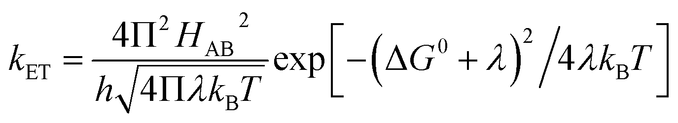 | (1) |
H AB denotes the electronic coupling between the donor and acceptor, −ΔG0 is the driving force for ET and λ denotes the total reorganization energy (λTotal).12,13 The value of λTotal is the sum of two components: λTotal = λIS + λOS.12,14,15 The inner-sphere contribution (λIS) is the energy related to the change in geometry of the active site during oxidation and reduction.14,16–18 It is mainly determined from the differences in equilibrium coordination geometry between the oxidized and reduced forms of the redox species involved in ET.19 In the case of ET proteins containing heme cofactors, the charge/hole created due to the redox event efficiently delocalizes over the porphyrin ring, which contributes to a low λIS value.15 The λOS for small molecules is the energy corresponding to the reorganization of the outer-sphere solvent shell adjacent to the redox species.14 For redox sites in metalloproteins, λOS describes changes in the polypeptide environment of the redox site (represented here as λP) as well as solvent rearrangement (represented here as λSolv) such that λOS = λP + λSolv.17,19 Typically, in electron transfer proteins, nature lowers λOS by harboring the redox site within a hydrophobic protein interior, excluding solvent, yielding a low λSolv.17 Although λ is a critical parameter in determining ET rates, its reliable measurement is a long-standing challenge to chemists and biochemists.18,20
Direct protein electrochemistry can serve as an experimental tool to evaluate the λ of redox-active species.21,22 In protein electrochemistry the desired protein can be immobilized on a self-assembled monolayer (SAM) modified Au electrode and the ET rate from the electrode to the protein can be determined as a function of temperature.23,24 The temperature-dependent ET rate yields the λ using Arrhenius analysis.15,25,26 The λ of cyt c from horse heart was previously determined electrochemically by Bowden and Tarlov et al. by immobilizing the protein on a 16-mercaptohexadecanoic acid (16-MHDA) modified Au electrode.23 The λ can also be determined using the self-exchange ET rates of proteins and can be estimated from theoretical calculations.20,27–31 The current electrochemical approach used in the determination of λ utilizes static electrochemical methods where mass transfer effects may affect the rates.22,23
Among the different members of the cytochrome c family, Hydrogenobacter thermophilus cytochrome c552 (HtWT) (Fig. 1A) is notable for the fluxionality of its axial methionine (Met) side chain ligated to the heme iron.32,33 Furthermore, NMR analysis of site-directed mutants of HtWT shows that replacing glutamine, the 64th residue, (Q64) with valine (HtQ64V) or asparagine (HtQ64N) restricts the orientation of the axial methionine, resulting in R-configured methionine in HtQ64V whereas HtQ64N has the methionine in the S configuration (Fig. 1B).32,34 These different configurations correspond to different orientations of the axial Met S p(π) orbitals relative to the heme plane and result in different orientations of the orbital hole on the oxidized heme, with proposed consequences for ET function.35 This makes Ht cyt c and its variants a valuable model system for the study of the effects of heme axial Met orientation on electronic structure and ET function, including how the heme active site structure influences λ of electron transfer.36
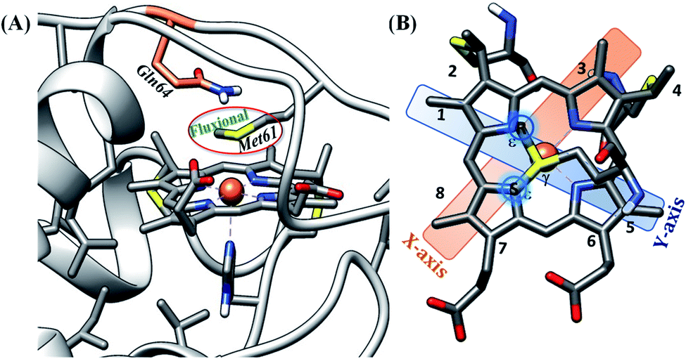 | ||
| Fig. 1 (A) Active site structure of cytochrome c552 (PDB ID: 1AYG) (HtWT, as mentioned in our study). Here, Q64 is presented in orange. (B) The heme c cofactor of HtWT covalently attached to the polypeptide via two thioether bonds. Two axial Met orientations are overlayed, one with the δS–εC bond along the X-axis (plane containing peripheral 3CH3–8CH3) denoted as Met in S configuration and the other with the δS–εC bond along the Y axis (plane containing peripheral 1CH3–5CH3) known as Met in R configuration. | ||
In this manuscript, we apply three distinct electrochemical techniques to determine λ for HtWT, HtQ64N, and HtQ64V. Our general approach is to measure ET rates as a function of temperature and obtain values for λ from Arrhenius analysis. Furthermore, manipulation of reaction conditions and comparison to computational data yields insights into contributions of polypeptide and solvent to λ. First, we use rotating disc electrochemistry (RDE) to determine the temperature dependence of the second-order ET rate and the corresponding reorganization energies. These experiments are performed under conditions where the proteins are freely diffusing, allowing the measurements of all the factors which can contribute to the λ. Hence, we refer to this as λTotal. This dynamic electrochemical technique for the determination of the λTotal is validated using two well-characterized redox systems, an inorganic complex ([Fe(CN)6]3−/4−) and an electron transfer protein (bovine heart cyt c, b-cyt c). For the other two approaches, the proteins were immobilized on a 6-mercaptohexanoic acid SAM-modified Au electrode. One of these ET rate measurements used a chronoamperometric technique and the other used cyclic voltammetry (CV) analyzed according to Laviron's formalism. Corresponding reorganization energies measured with the help of these approaches are denoted as λCA and λLV hereafter, respectively. Note that, in spite of the immobilization of the proteins on the functionalized electrodes, the contribution of the solvent component cannot be completely nullified when the reorganization energies are measured using the above-mentioned approaches. Thus both λCA and λLV includes the contribution of λIS, λP and partly λsolvent. However, DFT calculations performed on these mutants estimate the λIS and the contribution of the nearby residues to the λOS, i.e., λP, but does not include any contribution from λsolvent. The differences in the computed reorganization energies (λcal) among the protein variants obtained from DFT calculations are in good agreement with the differences in the reorganization energies obtained experimentally, suggesting that these differences in reorganization energy between the mutants originate from changes in the active site its immediate vicinity (i.e., λIS and λP). These calculations help to elucidate the contribution of the axial methionine orientation and its interaction with a second-sphere residue in determining reorganization energy and HAB, key factors determining rates in biological ET.
Experimental details
All reagents were of the highest grade commercially available and were used without further purification. Bovine heart cytochrome c, 6-mercaptohexanoic acid, and potassium hexafluorophosphate (KPF6) were purchased from Sigma-Aldrich. Disodium hydrogen phosphate dihydrate (NaH2PO4·2H2O), potassium hexacyanoferrate(III) (K3[Fe(CN)6]), and absolute ethanol were purchased from Merck.Instrumentation
All electrochemical experiments were performed using a CH instruments (CHI720D electrochemical analyzer) bi-potentiostat. Aqueous Ag/AgCl (saturated KCl) and platinum were used as reference and counter electrodes, respectively, throughout the experiments. Teflon® plate material evaluating cells (PTM, ALS Japan) used in our study were purchased from CH instruments. The rotating ring disc electrochemical setup (RRDE) from Pine research instrumentation (E6 series change disc tips with the AFE6M rotor) was used to obtain the RDE data.Protein expression and purification
Expression and purification of the proteins were done as described in the literature.32,34Construction of the electrodes
Electrochemical experiments
Au wafers, inserted in a plate material evaluating cell (the effective area for electrochemical studies is 0.45 cm2 once the Au wafer was inserted in plate material evaluating cell) were then washed with Milli-Q water thrice and dried under a stream of N2 gas. CV was performed with varying scan rates in 100 mM pH 7.3 sodium phosphate buffer containing 4 mM KPF6 using aqueous Ag/AgCl (saturated KCl) and platinum electrodes as reference and counter electrodes, respectively, at different temperatures noted in the results section.Surface coverage measurement
Surface coverage determinations of a 6-mercaptohexanoic acid monolayer on the modified Au electrode were done by reductive desorption method.40,41 The reductive desorption of the monolayer was done in an ethanolic solution of 0.5 M KOH under an argon atmosphere using aqueous Ag/AgCl (saturated KCl) and a platinum electrode as reference and counter electrode, respectively, by scanning from −0.2 V to −1.2 V at a 20 mV s−1 scan rate. The area under the cathodic peak gives the surface coverage of the monolayer on the Au disc.Density functional theory (DFT) calculations
The coordinates for HtWT were obtained from the protein data bank (PDB ID of HtWT is 1AYG).42 Peptide truncation was achieved by substituting –C(![[double bond, length as m-dash]](https://www.rsc.org/images/entities/char_e001.gif) O)NH groups with –C(O)H; these H were frozen in all calculations (Fig. 14). The model includes the proximal peptide loop including the two cysteine residues that are covalently attached to the heme and the axial His (residues 12–16). On the distal side of the heme, the peptide loop including the axial ligand M61 to the Q64 residue (which is being mutated) is included. It was further ensured that no hydrogen bonding interaction to the Q64 residue was excluded in this model. The structures of Q64V and Q64N mutants were obtained by replacing the glutamine residue (64th position, using P. aeruginosa cyt c551 numbering) in HtWT with valine and asparagine, respectively, and changing the orientation of the methionine according to the reported literature (Fig. 1B).32,34 In the case of HtWT, two sets of structures with axial Met in both R and S configurations for both oxidized and reduced heme were optimized. In the case of HtQ64V and HtQ64N, the structures were optimized with the axial Met in the R and S configuration, respectively. The axial Met orientation was kept constant during the calculations of oxidized and reduced state geometry in each of the structures. The geometries of HtWT, HtQ64V and HtQ64N were optimized using unrestricted BP86 and B3LYP functional with gradient correction with the help of Gaussian 03 version (g03) in the gas phase.43 The 6-31G(d) basis set was used for optimization of all of the atoms. Frequency calculations were performed on the optimized geometry to confirm that the minimum energy was obtained and the absence of any imaginary modes in these models. The 6-311+G(d) basis set was used on all of the atoms to determine the final energy of the models.44,45 The λ values and redox potential values were obtained as the summation of the reorganization energy of the oxidized complex (λox) and that of the reduced complex (λred).14,15,46–50 The value of λox can be calculated from the difference in energy between the Fe(III) at its optimized geometry and at the optimized geometry of Fe(III) within the Fe(II) structure. The difference in energy between the optimized Fe(II) structure and Fe(II) in the optimal structure for Fe(III) gives the value of λred. The spin density distributions were determined using the cubegen utility of Gaussian 03 with an isovalue of 0.0004 and the LUMOs were created using the Chemissian software with an isovalue of 0.035.
O)NH groups with –C(O)H; these H were frozen in all calculations (Fig. 14). The model includes the proximal peptide loop including the two cysteine residues that are covalently attached to the heme and the axial His (residues 12–16). On the distal side of the heme, the peptide loop including the axial ligand M61 to the Q64 residue (which is being mutated) is included. It was further ensured that no hydrogen bonding interaction to the Q64 residue was excluded in this model. The structures of Q64V and Q64N mutants were obtained by replacing the glutamine residue (64th position, using P. aeruginosa cyt c551 numbering) in HtWT with valine and asparagine, respectively, and changing the orientation of the methionine according to the reported literature (Fig. 1B).32,34 In the case of HtWT, two sets of structures with axial Met in both R and S configurations for both oxidized and reduced heme were optimized. In the case of HtQ64V and HtQ64N, the structures were optimized with the axial Met in the R and S configuration, respectively. The axial Met orientation was kept constant during the calculations of oxidized and reduced state geometry in each of the structures. The geometries of HtWT, HtQ64V and HtQ64N were optimized using unrestricted BP86 and B3LYP functional with gradient correction with the help of Gaussian 03 version (g03) in the gas phase.43 The 6-31G(d) basis set was used for optimization of all of the atoms. Frequency calculations were performed on the optimized geometry to confirm that the minimum energy was obtained and the absence of any imaginary modes in these models. The 6-311+G(d) basis set was used on all of the atoms to determine the final energy of the models.44,45 The λ values and redox potential values were obtained as the summation of the reorganization energy of the oxidized complex (λox) and that of the reduced complex (λred).14,15,46–50 The value of λox can be calculated from the difference in energy between the Fe(III) at its optimized geometry and at the optimized geometry of Fe(III) within the Fe(II) structure. The difference in energy between the optimized Fe(II) structure and Fe(II) in the optimal structure for Fe(III) gives the value of λred. The spin density distributions were determined using the cubegen utility of Gaussian 03 with an isovalue of 0.0004 and the LUMOs were created using the Chemissian software with an isovalue of 0.035.
Results and analysis
Electron transfer kinetics from rotating disc electrochemistry
Rotating Disc Electrochemistry (RDE) is used to determine the λ for redox active species in solution. To establish the validity of the method first RDE is used to determine the λ of well-known redox species like [Fe(CN)6]4−/3− and bovine cyt c (b-cyt c) and then we proceed to evaluate the λ for Ht cyt c.| i−1 = iK(E)−1 + iL−1 | (2) |
| iK = nFA[substrate]kcatΓcat | (3) |
| iL = 0.62nFA[substrate](Dsubstrate)2/3ω1/2υ−1/6 | (4) |
Here, n = number of electrons transferred to the substrate (redox active species like [Fe(CN)6]3− or cyt c), F = Faraday constant, A = macroscopic area of the electrode (for Au disc, A is 0.19625 cm2), [substrate] = concentration of substrate (here, the redox active species is considered as the substrate) in solution, kcat = second-order rate constant (here, only ET happens from the electrode to the substrate and thus it will signify kET), Γcat = catalyst concentration in moles cm−2 (in our case the electroactive sites of the Au electrode, either modified or bare acts as catalyst and the surface coverage of the SAM on the Au electrode is equivalent to the catalyst concentration), Dsubstrate = diffusion coefficient of the substrate in the solution, ω = angular velocity of the disc and υ = kinematic viscosity of the solution (0.009 cm2 s−1).51 The slope of the linear plot of i−1 (inverse of current at various rotation rates) versus ω−1/2 (inverse square root of the angular rotation rate) gives the number of electrons involved in the process (eqn (2) and (4)). The second-order rate constant for ET (kET) occurring from the electrode to the substrate is determined from the intercept of the i−1versus ω−1/2 plot (Fig. S2;†eqn (2) and (3)). This second-order ET rate is calculated at several applied potentials between −0.05 V to −0.15 V with a gap of 5 mV in the mass transfer limited region of the current i.e., the plateau current. The determined rate is ∼2.51 ± 0.14 × 10⁵ M−1 s−1 at 283 K and the rate increases to ∼3.16 ± 0.15 × 10⁵ M−1 s−1, ∼4.56 ± 0.11 × 10⁵ M−1 s−1 and 5.06 ± 0.22 × 10⁵ M−1 s−1 at 288 K, 293 K and 298 K, respectively (Fig. S3†). The diffusion coefficient of K3[Fe(CN)6] in 100 mM pH 7 sodium phosphate buffer (containing 100 mM KPF6 as the supporting electrolyte) was calculated from the plot of ipversus the square root of the scan rate (ν1/2) (Fig. S4†) using the following equation:
| ip = 0.4463npFACcat(npFνD/RT)1/2 | (5) |
Here, ip is the maximum non-catalytic current, A is the area of the electrode, Ccat, ν, and D represent the concentration of the redox active species, scan rate and diffusion coefficient, respectively.52,53 The calculated Dcat value at 298 K was found to be 7.52 × 10⁻⁶ cm2 s−1 which is in good agreement with the previously determined Dcat value of the same.54 The slope of the K–L plot (i−1versus ω−1/2, eqn (4)) at different potentials at the mass transfer limited region corresponds to the theoretical estimate for a 1 e− slope (Fig. S5†). This is consistent with a 1 e− transfer by ferricyanide. Thus, the rate obtained from the K–L analysis of the RDE data can be interpreted as the rate of ET from the electrode to [Fe(CN)6]3− in pH 7 sodium phosphate buffer.
ET rates obtained at different temperatures allows us to determine the value of total reorganization energy (λTotal) of [Fe(CN)6]3− in solution. The Marcus density-of-states model for ET processes can be used to formulate the Arrhenius plot of ln(kT−1/2) versus T−1 (eqn (6)).55,56
| λ = −4.03 d(ln[kETT−1/2])/d[T−1] | (6) |
Assuming λTotal to be temperature independent, its numerical value is determined from the slope of the plot of ln[kETT−1/2] versus T−1(Fig. 2A).55,56 The λTotal obtained at different potentials (Fig. 2B, Fig. S6†) in the mass transfer limited region indicates a value of 1.41 ± 0.04 eV. Since an aqueous solution of [Fe(CN)6]3− is used, the λTotal determined from the RDE analysis includes both inner-sphere and outer-sphere contributions (λTotal = λIS + λOS). This value is close to that determined from photoelectron spectroscopic measurements (1.47 eV).57 These results validate the use of RDE as an experimental tool for the determination of λTotal of a redox active species in solution.
 | ||
| Fig. 2 (A) Arrhenius semilogarithmic plot of ln(kT−1/2) versus T−1 for 1 mM K3[Fe(CN)6] in 100 mM pH 7 sodium phosphate buffer containing 150 mM KPF6 at three different potentials. From these slopes λTotal values at different potentials were determined. The remaining data are shown in Fig. S6.† (B) Values of λTotal determined at various potentials in the mass transfer limited region of the RDE voltammograms. Here, freshly washed Au disc was used as working electrode, aqueous Ag/AgCl (saturated KCl) and Pt electrodes were used as reference and counter electrode, respectively. | ||
The native protein structure is preserved upon binding of cyt c to the 6-mercaptohexanoic acid SAM modified electrode70,71 and the protein experiences a strong electric field near the electrode surface.72–76 Previously, it has been shown that under strong electric field the reorientation of the protein at the electrode surface is restricted and it is the rate-limiting step of the ET event.70,71,76 Murgida and coworkers have observed kinetic isotope effect (KIE) during ET in the presence of short SAM.72,77 A KIE value of 1.2 was observed for the C6 carboxylate SAM (used in our experiment) and the value increases in going to thinner SAMs. But, for the thicker SAMs (n ≥ 11) no such difference in the ET rate was observed in H2O and D2O. The alteration of the hydrogen bonding interactions in the protein and protein/SAM interface were held responsible for this observed KIE under high electric field. In a recent study, a prominent KIE was seen during ET through thiol SAMs modified Au electrode to the covalently attached ferrocene.78 The value of KIE measured was ∼2 for C8SH modified Au electrode. The rate of H/D exchange is fast in the case of C8SH in compared to the same in C16SH SAM as the number of defects increases for thinner SAMs. Thus, this interfacial KIE at the Au–thiol interface may be a contributor towards the observed KIE during ET observed by Murgida and co-workers. Due to the presence of strong electric field the dipole moment of the adsorbed protein tends to align more effectively resulting in an average perpendicular orientation of the heme active site plane to the surface of the modified electrode.71 This orientation may not be the best orientation in terms of efficient ET but the restricted orientation helps us to understand the other factors in thee active site that affect the ET.
The CV of b-cyt c (Fig. S8†) with the modified electrode indicates a diffusion-limited current. A plot of ipversus the square root of the scan rate (ν1/2) (Fig. S9†) yields (using eqn (5)) the diffusion coefficient of b-cyt c in pH 6 sodium phosphate buffer with 150 mM KPF6 as 2.9 × 10⁻⁶ cm2 s−1. The value of Dcat determined here is in close agreement with the value 1.1 × 10⁻⁶ cm2 s−1 previously reported for b-cyt c.79 RDE shows increasing current with an increase in rotation speed (Fig. S10†). With the help of K-L analysis both of the number of e− involved and the rates of ET are estimated. The surface coverage of 6-mercaptohexanoic acid SAM was determined by reductive desorption method described elsewhere40 and was calculated to be 4.8 × 10⁻¹¹ moles cm−2 (area under the corresponding cyclic voltammograms shows the concentration of the proteins present at the modified electrodes are nearly same, Table ST1†). The slope of the K–L plot collected over a reasonable potential range between 0.05 V to 0.12 V is close to the value of theoretical 1 e− slope (Fig. S11†). The second-order rate constant was determined from the intercept of the K–L plot at eleven different potentials from 0.05 V to 0.12 V in the mass transfer limited region of the RDE current (Fig. S12†). The rates were determined to be 5.83 ± 0.8 × 10⁴ M−1 s−1, 6.42 ± 0.7 × 10⁴ M−1 s−1, 9.62 ± 1.4 × 10⁴ M−1 s−1, 1.17 ± 1.7 × 10⁵ M−1 s−1, 1.25 ± 0.20 × 10⁵ M−1 s−1 and 1.43 ± 0.20 × 10⁵ M−1 s−1 at 283 K, 288 K, 293 K, 298 K, 303 K and 308 K, respectively. Rates at different temperatures allow the estimation of λTotal using an Arrhenius semilogarithmic plot of ln(kT−1/2) versus T−1 as discussed earlier (Fig. 3). The λTotal is determined to be 1.06 ± 0.05 eV which agrees well with the reported values of reorganization energy of cyt c proteins which vary between 0.8 eV and 1.2 eV depending on the redox partner.1,2,25,50,80–90
 | ||
| Fig. 3 (A) Arrhenius semilogarithmic plot of ln(kT−1/2) versus T−1 for 100 μM bovine heart cyt c in 100 mM pH 6 sodium phosphate buffer with 150 mM KPF6 as supporting electrolyte, at three different potentials. From these slopes λTotal was determined. The remaining data are given in Fig. S13.† (B) λTotal values determined at various potentials in the mass transfer limited region of the RDE voltammograms. Here 6-mercaptohexanoic acid modified Au disc was used as working electrode, aqueous Ag/AgCl (saturated KCl) and Pt electrodes were used as reference and counter electrode respectively. | ||
Thus, the λTotal values obtained using K–L analysis of RDE data for two different well-defined redox active species, [Fe(CN)6]3− and b-cyt c, agree well with the values of reorganization energy values reported earlier, which validates the approach used here. This method is now extended to cyt c552 from Hydrogenobacter thermophilus (HtWT) and two of it's site-directed mutants with altered heme axial Met orientations to gain insight into how the heme axial Met orientation and second-sphere interactions at the active site influence the reorganization values in these proteins. Note that, for these mutants, λTotal values were evaluated by calculating the rates at three different temperatures instead of four or six. A different set of data for the determination of λTotal using the rates at three different temperatures (Fig. S14–S18†) matches exactly with the value evaluated with the rates at six different temperature for b-cyt c. This comparison is provided in the ESI (Fig. S14–S18).†
 | ||
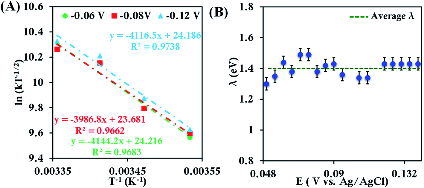
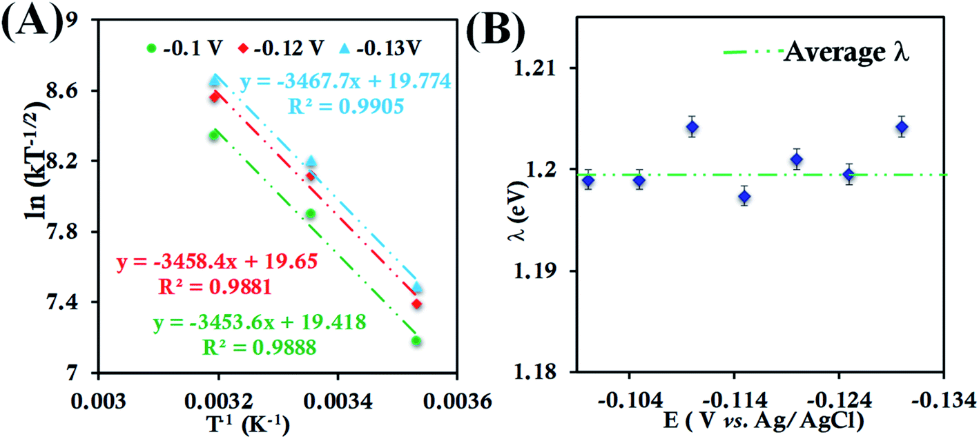
| Fig. 4 (A) Arrhenius semilogarithmic plot of ln(kT−1/2) versus T−1 for 135 μM HtWT in pH 6 sodium phosphate buffer with 150 mM KPF6 as supporting electrolyte at three different potentials. The remaining data are shown in Fig. S22.† From these slopes λTotal was determined. (B) λTotal values at different potentials determined from the mass transfer limited region of the RDE plots. Here, 6-mercaptohexanoic acid-modified Au disc was used as working electrode, aqueous Ag/AgCl (saturated KCl) and Pt electrodes were used as reference and counter electrode respectively. | ||
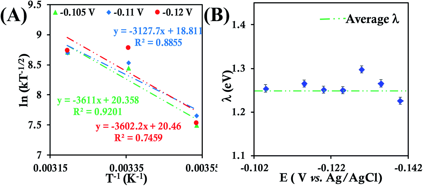
In the case of HtQ64V in 100 mM pH 6 sodium phosphate buffers containing 150 mM KPF6, the temperature dependent cyclic voltammograms show responses near −0.015 V (Fig. S23†). The second-order ET rate constant determined from RDE (Fig. S24†) is 5.98 ± 0.52 × 10⁴ M−1 s−1 at 298 K, which decreases to 2.88 ± 0.27 × 10⁴ M−1 s−1 at 283 K and increases to 9.73 ± 0.90 × 10⁴ M−1 s−1 at 313 K (Fig. S25†). The RDE data and corresponding K–L plot for HtQ64V obtained at these temperatures were used to obtain the λTotal. The λTotal is determined to be 1.20 ± 0.01 eV across the mass transfer limited potential region (Fig. 5).
 | ||
| Fig. 5 (A) Arrhenius semilogarithmic plot of ln(kT−1/2) versus T−1 for 135 μM HtQ64V in 100 mM pH 6 sodium phosphate buffer with 150 mM KPF6 as supporting electrolyte at three different potentials. The remaining data are shown in Fig. S26.† From these slopes λTotal was determined. (B) λTotal values determined at various potentials in the mass transfer limited region of the RDE plots. Here, 6-mercaptohexanoic acid modified Au disc was used as the working electrode, aqueous Ag/AgCl (saturated KCl) and Pt electrodes were used as reference and counter electrodes, respectively. | ||
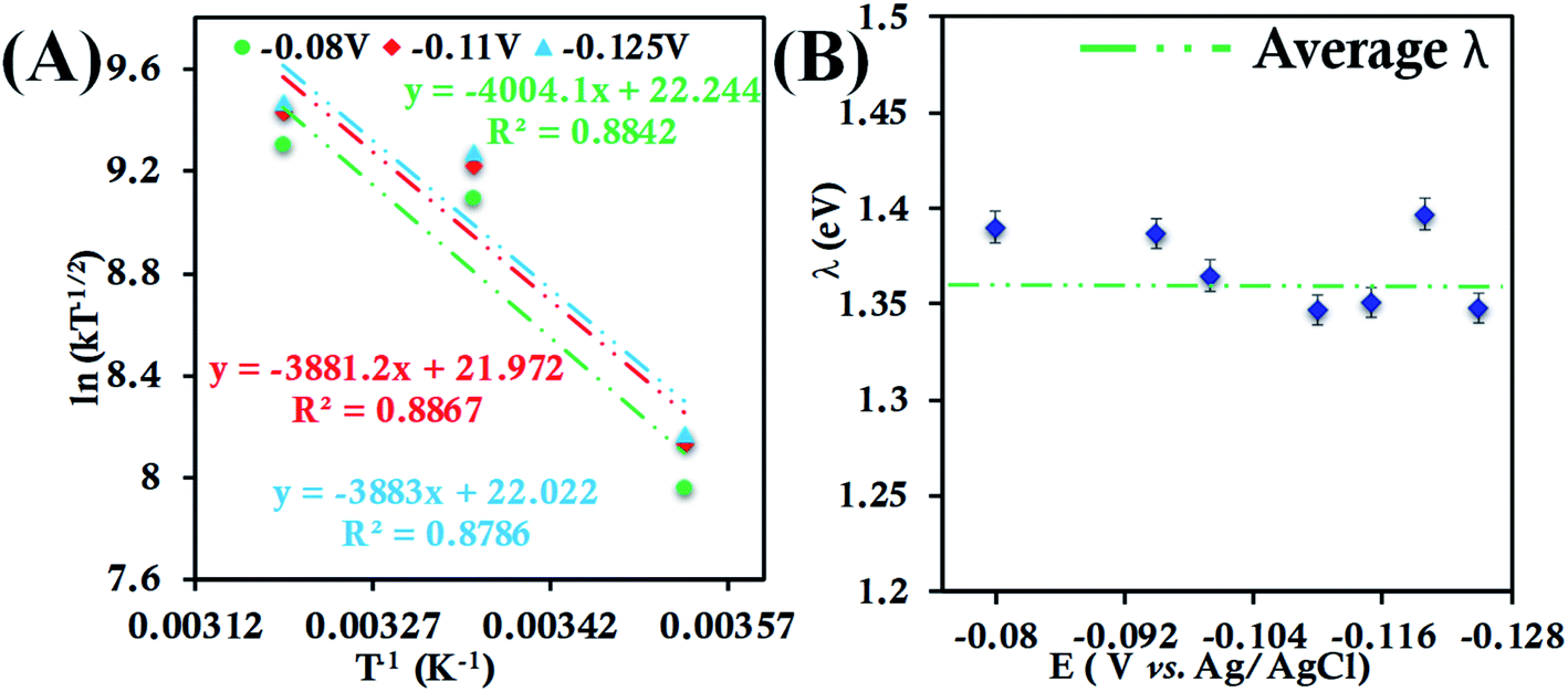
Cyclic voltammograms and RDE voltammograms of HtQ64N in 100 mM pH 6 sodium phosphate buffer (150 mM KPF6) using a 6-mercaptohexanoic acid SAM-modified Au electrode as a working electrode were obtained at different temperatures (Fig. S27, S28A, C and E†). K–L analysis at different temperatures (Fig. S28B, C and D†) yields second-order kET values of 3.93 ± 0.61 × 10⁴ M−1 s−1 (at 283 K), 9.11 ± 0.80 × 10⁴ M−1 s−1 (at 298 K) and 11.90 ± 1.30 × 10⁴ M−1 s−1 (at 313 K) (Fig. S29†). The λTotal of HtQ64N in 100 mM pH 6 sodium phosphate buffer is determined to be 1.26 ± 0.02 eV using Arrhenius semilogarithmic plot (ln kT−1/2versus T−1) (Fig. 6A) with varying potentials (Fig. 6B).
 | ||
| Fig. 6 (A) Arrhenius semilogarithmic plot of ln(kT−1/2) versus T−1 for 135 μM HtQ64N in 100 mM pH 6 sodium phosphate buffer with 150 mM KPF6 as supporting electrolyte at three different potentials. The remaining data are shown in Fig. S30.† From these slopes λTotal was determined. (B) λTotal distribution according to various potential in the mass transfer limited region of the RDE plots. Here 6-mercaptohexanoic acid modified Au disc was used as working electrode, aqueous. Ag/AgCl (saturated KCl) and Pt electrodes were used as reference and counter electrode respectively. | ||
These values of λTotal for HtWT and two of its mutants determined using an RDE technique are similar to each other and of a magnitude expected based on other determinations of reorganization energies for cytochromes c. The values of λTotal differ among the proteins, which may reflect effects of different orientations of the axial methionine and/or the second-sphere residues present in the active site. These relationships are explored further below. Importantly, the reorganization energies obtained using RDE are the λTotal values including both inner-sphere contributions and outer-sphere contributions (consisting of the contributions from both of the protein and the solvent) because the species are freely diffusing in solution. Alternatively, if reorganization energy is determined for proteins immobilized on electrodes, one may expect the outer-sphere contribution to λ, albeit small for a protein like cyt c, to decrease because of the displacement of solvent from the protein surface.6 In the case of these cyt c proteins, this would specifically involve the solvent-exposed heme edge through which ET is proposed to occur. This effect can be measured for cyt c immobilized on electrodes bearing a negative charge in solutions at relatively low electrolyte concentration.23 These results are described in the following sections.
Electron transfer kinetics from chronoamperometry
Here, we determine the apparent heterogeneous electron transfer (ET) rate constant (kapp) of redox active species (b-cyt c, HtWT, HtQ64V and HtQ64N) by potential step chronoamperometry after attaching the species electrostatically to carboxyl-terminated alkyl thiol self-assembled monolayers modified Au electrode.39,91 During chronoamperometry, the potential of the electrode is varied from the initial potential, taken as the E1/2 of the redox species, to a final potential (E′) to drive the oxidation or reduction of the same. At a particular overpotential (E′ − E1/2) the current follows an exponential relationship with time according to:39,51i = kappQ![[thin space (1/6-em)]](https://www.rsc.org/images/entities/char_2009.gif) exp(−kappt) exp(−kappt) | (7) |
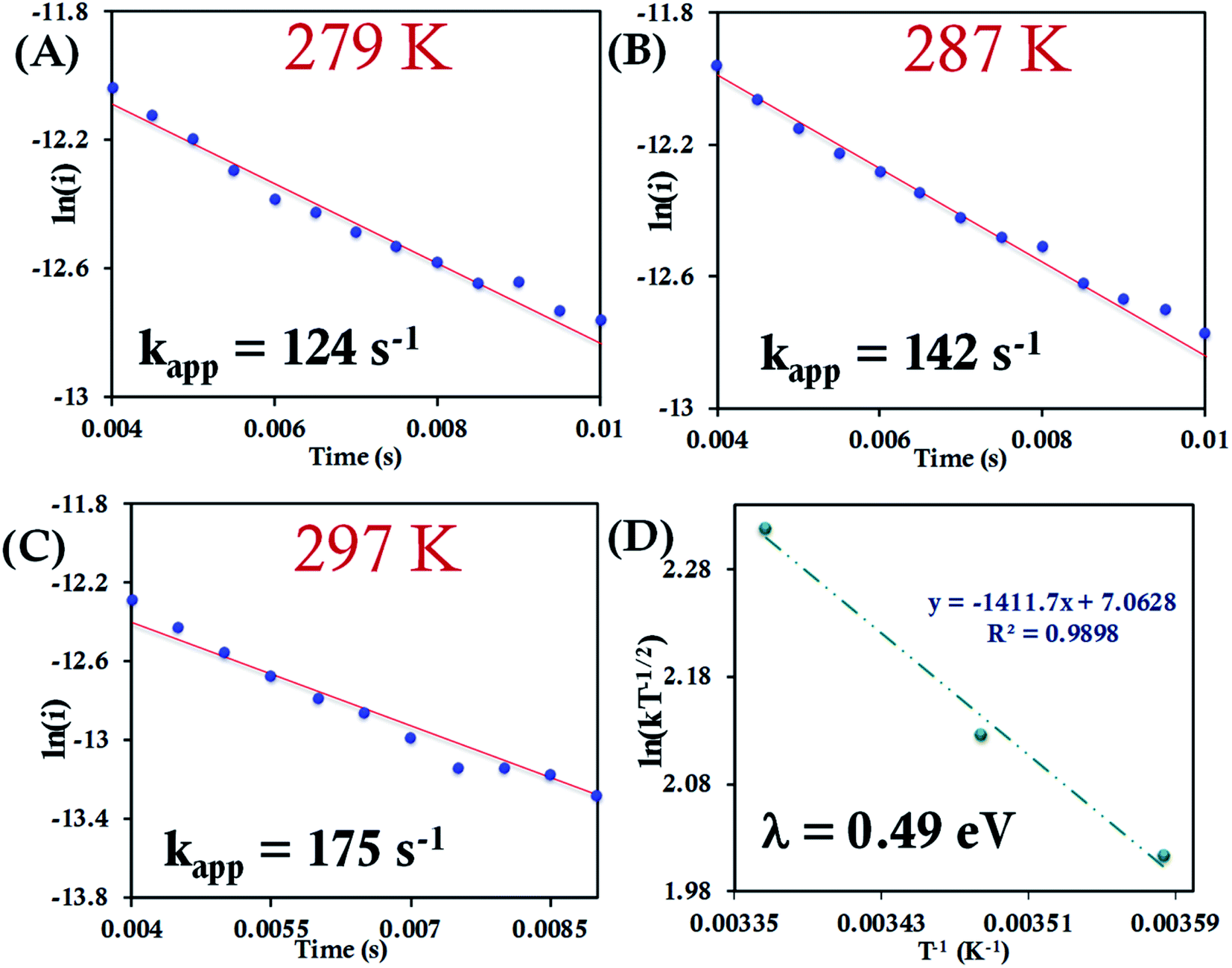 | ||
| Fig. 7 (A–C) Chronoamperometric semilogarithmic plots for of ln(i) versus time with regression fittings at different temperatures for b-cyt c attached to a 6-mercaptohexanoic acid modified Au electrode. The slope of linear fitting gives the apparent ET rate (eqn (7)). The kapp and corresponding temperature are indicated in each graph. The overpotential applied was −50 mV. (D) Arrhenius semilogarithmic plot of ln(kT−1/2) versus T−1 of the results from panels A, B, C. From the slope λCA was determined (eqn (6)) as indicated in the graph. Here aqueous Ag/AgCl (saturated KCl) and Pt electrodes were used as reference and counter electrode respectively. | ||
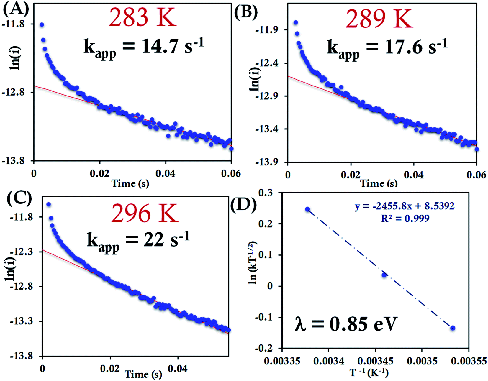 | ||
| Fig. 8 (A–C) Chronoamperometric semilogarithmic plot of ln(i) versus time with their regression fittings at different temperature for HtWT attached to 6-mercaptohexanoic acid modified Au wafer. The slope of linear fitting gives the apparent ET rate according to eqn (7). The temperature and kapp are indicated in the graph. The overpotential applied was −50 mV. (D) Arrhenius semilogarithmic plot of ln(kT−1/2) versus T−1 for HtWT attached to a modified Au wafer in pH 7.3 sodium phosphate buffer (100 mM concentration with 4 mM KPF6 as supporting electrolyte). From the slopes λCA was determined as indicated in the graph. Aqueous Ag/AgCl (saturated KCl) and Pt electrodes were used as reference and counter electrode respectively. | ||
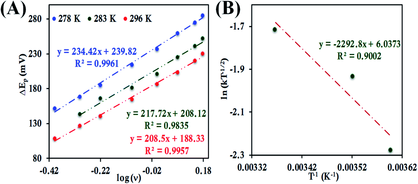
For the HtQ64V mutant, which has the axial Met fixed in the “R” configuration (Fig. 1), the interfacial ET rates were found to be 10.5 ± 1.5 s−1, 12.6 ± 1.1 s−1 and 16.0 ± 1.8 s−1 281 K, 286 K and 297 K, respectively (Fig. 9A–C and S39†). An λCA value of 0.69 ± 0.01 eV was determined for HtQ64V by fitting to eqn (5) as described earlier (Fig. 9D).
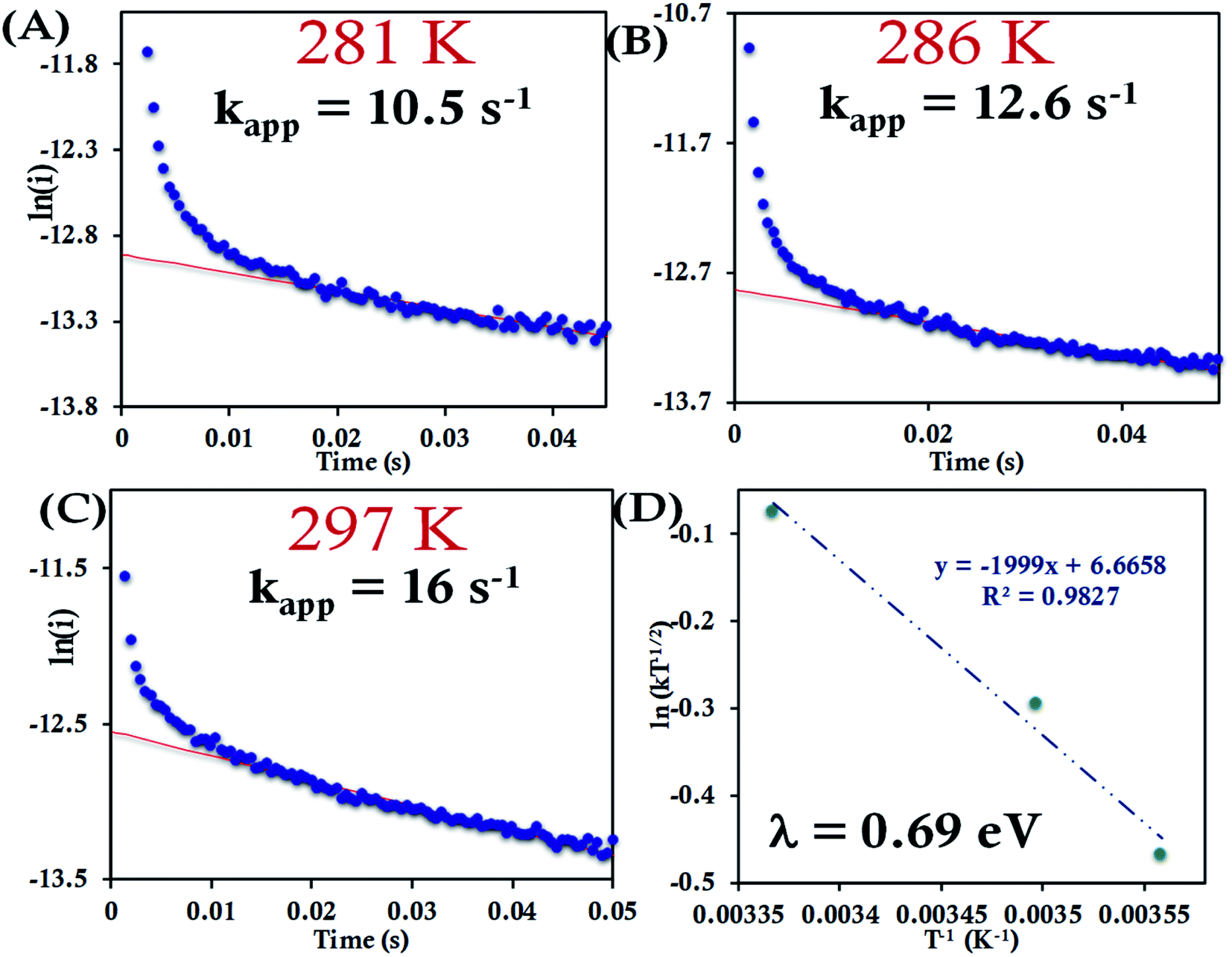 | ||
| Fig. 9 (A–C) Chronoamperometric semilogarithmic plot of ln(i) versus time with their regression fittings at different temperature for HtQ64V attached to 6-mercaptohexanoic acid modified Au wafer. The slope of linear fitting gives the apparent ET rate. The temperature and kapp are indicated in the graph. The overpotential applied was −50 mV. (D) Arrhenius semilogarithmic plot of ln(kT−1/2) versus T−1 for HtQ64V attached to 6-mercaptohexanoic acid terminated Au wafer in 100 mM pH 7.3 sodium phosphate buffer with 4 mM KPF6 as supporting electrolyte. From the slopes λ was determined as indicated in the graph. Here aqueous Ag/AgCl (saturated KCl) and Pt electrodes were used as reference and counter electrode respectively. | ||
The HtQ64N variant has the axial Met in the S configuration (Fig. 1). Here, it is found to have a slower interfacial ET rate than HtWT and HtQ64V. The estimated rates are 6.5 ± 0.8 s−1, 7.3 ± 1 s−1, and 9.8 ± 1.2 s−1 at 283 K, 287 K, and 297 K, respectively, when attached to the modified Au electrode (Fig. 10A–C, Fig. S40†). The λCA determined using these values was 0.81 ± 0.02 eV, which falls between the λCA of HtWT and HtQ64V (Fig. 10D, Table 1).
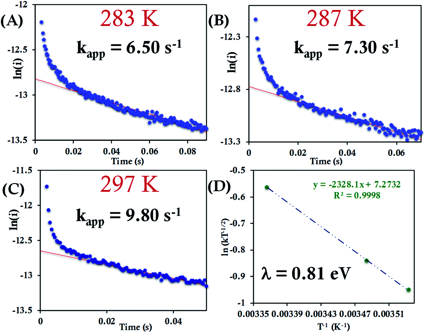 | ||
| Fig. 10 (A–C) Chronoamperometric semilogarithmic plot of ln(i) versus time with their regression fittings at different temperature for HtQ64N attached to 6-mercaptohexanoic acid modified Au wafer. The slope of linear fitting gives the apparent ET rate. The temperature and kapp were indicated in the graph. The overpotential applied was −50 mV. (D) Arrhenius semilogarithmic plot of ln(kT−1/2) versus T−1 for HtQ64N attached to 6-mercaptohexanoic acid modified Au wafer in pH 7.3 phosphate buffer. From the slopes λCA was determined and indicated in the graph. Here, aqueous Ag/AgCl (saturated KCl) and Pt electrodes were used as reference and counter electrodes, respectively. | ||
| Species | λ Total (eV) | λ CA (eV) | λ LV (eV) | λ Rep (eV) |
|---|---|---|---|---|
| a Reorganization energy value measured using RDE. b Reorganization energy value measured using Chronoamperometry. c Reorganisation energy value measured using CV following Laviron's formalism. d Reorganization energy value reported earlier. | ||||
| [Fe(CN)6]3− | 1.41 (±0.04) | — | — | 1.47 |
| b-cyt c | 1.06 (±0.05) | 0.49 (±0.01) | — | 1.00 |
| HtWT | 1.36 (±0.03) | 0.85 (±0.01) | 0.82 (±0.02) | |
| HtQ64V | 1.20 (±0.01) | 0.69 (±0.01) | 0.71 (±0.01) | |
| HtQ64N | 1.26 (±0.02) | 0.80 (±0.01) | 0.80 (±0.01) | |
Electron transfer kinetics from cyclic voltammograms using Laviron's approach
The standard rate constant (k0) for heterogeneous ET between the electrode and an adsorbed redox active species can be determined by Laviron's method as well.94 Based upon the Butler–Volmer approach, this method requires sufficient separation between the cathodic and anodic peak potential (ΔEp > 100 mV) at different scan rates. The resulting transfer coefficient (α) is a measure of the symmetry of the energy barrier of the redox reaction and is generally about 0.5 for the ideal case.37 However, the value of α may vary depending upon conditions imposed on the redox reaction and consequently determination of α is an important step for the determination of k0.37 The anodic and cathodic peak potentials (Epa and Epc, respectively) were plotted separately versus lnν to determine the value of α from the slope using the eqn (8) and (9).| EPC = E − (RT/αnF)ln[αnF/RTk0] − (RT/αnF)ln(ν) | (8) |
| EPA = E + [RT/(1 − α)nF]ln[(1 − α)nF/RTk0] + [RT/(1 − α)nF] ln(ν) | (9) |
In these expressions, EPA and EPC are the anodic and cathodic peak potentials, E is the formal potential of the redox-active species (here it is E1/2). ν is the scan rate in V s−1 and n = 1. Designations of k0 and α are mentioned above. R, T, n and F have their usual meanings.
At higher scan rates when ΔEp >100 mV, k0 was determined from the intercept of the ΔEp and α value following eqn (10).37 The details of the approach can be found elsewhere.15,95
| ΔEp = 2.3RT/α(1 − α)nF[αlog(1 − α) + (1 − α)log(α) − log(RT/nFν) − log(k0)] | (10) |
For b-cyt c, at 297 K a ΔEp value of 29 mV at 1 V s−1 when it is directly attached to the 6-mercaptohexanoic acid terminated Au electrode is obtained, indicating a very fast ET rate, and thus the condition required for applying the Laviron's approach, i.e., ΔEp > 100 mV can only be obtained at very high scan rates (Fig. S31†). Thus, Laviron's approach is restricted to the determination of ET rate for HtWT cyt c and its two mutants, namely HtQ64V and HtQ64N, for which the ΔEp > 100 mV over a wide range of scan rates.
ν (eqn (8) and (9)), the value of α is estimated to be 0.5, 0.48 and 0.57 at 278 K, 286 K and 296 K, respectively (Fig. S41 and S42†). The slope of the plot of ΔEpversus logν and the value of α yields the estimated k0 values of 5.64 ± 0.23 s−1, 7.82 ± 0.35 s−1, and 9.79 ± 0.85 s−1 at 278 K, 286 K and 296 K, respectively (Fig. 11A), which in turn allows the estimation of the value of λLV to be 0.82 ± 0.02 eV using the Arrhenius equation (eqn (5)) as discussed above (Fig. 11B). Notably, the value of λLV determined using Laviron's approach is very close to the value determined from chronoamperometry (0.85 eV, Table 1, vide supra).
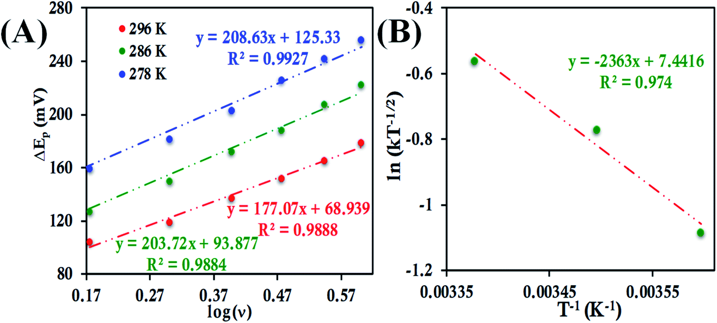 | ||
| Fig. 11 (A) Plot of ΔEpversus logν for HtWT attached to 6-mercaptohexanoic acid modified Au wafer at pH 7.3 phosphate buffer at different temperatures. (B) Arrhenius semilogarithmic plot of ln(kT−1/2) versus T−1 for the same. Here, aqueous Ag/AgCl (saturated KCl) and Pt electrodes were used as reference and counter electrode respectively. | ||
In the case of HtQ64V the α values were evaluated as 0.51, 0.40 and 0.56 at 277 K, 282 K, and 298 K, respectively, using the above-defined procedure (Fig. S43 and S44†). The rates were found to be 3.38 ± 0.13 s−1, 4.14 ± 0.18 s−1, and 5.97 ± 0.3 s−1 at 277 K, 282 K, 298 K, respectively, and the corresponding λLV was determined to be 0.71 ± 0.01 eV, again consistent with the chronoamperometric results (0.69 ± 0.01 eV) (Fig. 12).
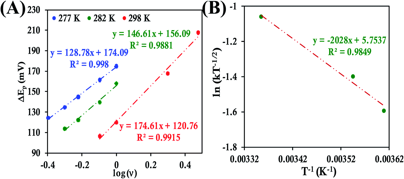 | ||
| Fig. 12 (A) Plot of ΔEpversus logν for HtQ64V attached to 6-mercaptohexanoic acid modified Au wafer at pH 7.3 phosphate buffer at different temperatures. (B) Arrhenius semilogarithmic plot of ln(kT−1/2) versus T−1 for the same. Here, aqueous Ag/AgCl (saturated KCl) and Pt electrodes were used as reference and counter electrode respectively. | ||
Determination of the k0 of HtQ64N attached to the modified Au electrode, using the same approach, yielded rates of 1.17 ± 0.3 s−1, 2.4 ± 0.07 s−1 and 3.09 ± 0.08 s−1 at 278 K, 283 K and 296 K, respectively (Fig. 13A). The corresponding α is determined to be 0.54, 0.52 and 0.51 at 278 K, 283 K and 296 K, respectively (Fig. S45 and S46†). The value of λLV estimated using Arrhenius analysis was found to be 0.80 ± 0.01 eV using the variable temperature ET rates (Fig. 13B) which is similar to the value obtained from chronoamperometry (also 0.80 ± 0.01 eV).
 | ||
| Fig. 13 (A) Plot of ΔEpversus logν for HtQ64N attached to 6-mercaptohexanoic acid modified Au wafer at pH 7.3 phosphate buffer at different temperatures. (B) Arrhenius semilogarithmic plot of ln(kT−1/2) versus T−1 for the same. Here, aqueous Ag/AgCl (saturated KCl) and Pt electrodes were used as reference and counter electrode respectively. | ||
The experimental values of reorganization energy determined using various electrochemical techniques as well as previously reported values ([Fe(CN)6]3− and b-cyt c) are shown in Table 1. The values of λ, obtained using RDE, are much larger than the values obtained using CA and Laviron's analysis, but the latter two are very similar to each other for each protein. This difference is expected as the RDE technique reports ET parameters from species in solution diffusing to interact with the electrode, while the ET parameters from CA and Laviron's analysis represent those obtained from cyt c immobilized on electrodes. It is reasonable to assume that the contribution of λSolv to λOS is higher when the protein is in solution relative to the situation when the protein is immobilized on the surface as the λSolv component to λOS is reduced. Thus, the difference between the values obtained from RDE (which assesses a diffusing redox species) and CA or Laviron's approach (which assess an immobilized redox species) represents a lower limit of the contribution of λSolv to λOS. This assumes that there is minimal structural perturbation of the cyt c protein during immobilization.25 The λ obtained using the CA and Laviron's approaches then represents mostly λIS and λP. In the case of b-cyt c this analysis appears to be consistent with previous literature reports on overall λ and λIS + λP for horse heart cyt c (Table 1, column 5) i.e., the λTotal is 1 eV and the λIS + λP is ∼0.5 eV. For HtWT, the λSolv and λIS + λP are 0.51 eV and 0.85 eV, respectively, suggesting that the λIS and λP of cyt c from Ht is much higher than that of cyt c from bovine heart.
Density functional theory (DFT) calculations
Geometry-optimized DFT calculations are used to estimate the λIS of HtWT and its mutants (Fig. S47†).14 The axial methionine ligand in the HtWT protein fluctuates between two different conformations; the R and the S states. In the R-state the methionine S–CH3 bond is oriented along the Y-axis (plane containing peripheral 1CH3–5CH3) of the heme and in the S-state it is rotated 90° and is oriented along the X axis of the heme (plane containing peripheral 3CH3–8CH3) (Fig. 14 and 15). The Q64V mutant has the methionine in the R state whereas the Q64N mutant has the methionine in the S-state.32,34 The calculated reorganization energy (λcal = λIS) for HtWT in the S-state and R-state are 0.34 eV and 0.31 eV, respectively; this difference reflects the effect of the axial Met configuration only. The λcal for Q64V (R-state) and Q64N (S-state) are 0.21 eV and 0.29 eV, respectively. While these variants have different Met configurations, they also have different interactions between residue 64 and the axial Met. While the absolute values of the reorganization energies are lower (using DFT) than the experimentally determined (λCA or λLV) values (as only a part of the protein is being modelled computationally, resulting in small contribution of the total λP), the difference between them is in very good agreement with the experimental data. For example, the experimentally determined λIS + λP of the Q64N and the Q64V mutants are lower than that of the HtWT by 0.04 eV and 0.16 eV, respectively, whereas the λcal for the S-state of Q64N and R-state of Q64V mutants are lower than HtWT (average of R-state and S-state) λcal by 0.04 eV and 0.12 eV, respectively. Thus, the factors responsible for the difference in the experimentally estimated value of λIS + λP are reflected in the computational model as well, i.e., the differences in the λP mostly originate from the protein fragment modelled in the DFT calculations.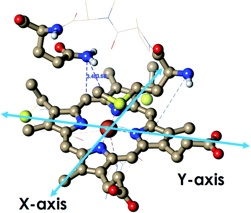 | ||
| Fig. 14 The active site structure of HtWT where methionine present in R conformation used for DFT calculations (PDB ID: 1AYG). | ||
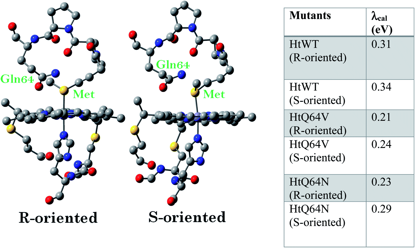 | ||
| Fig. 15 The computational model of the HtWT heme pocket used for DFT calculations and the calculated λcal values of HtWT and two of its mutants with both of R and S axial Met configurations. Hydrogens are omitted for clarity. | ||
Computational data indicate that the λcal of HtWT in its S-state is higher than the λcal of the R-state by 0.03 eV. Thus, the rest of the difference seen between these variants (0.09 eV) must be derived from the differences in the changes in geometry of the active site upon change of redox state. The λcal values are also evaluated by optimizing the geometries using B3LYP functional instead of BP86 and the same trend in the calculated λ values follow (Table ST1†).
The change of geometry upon oxidation is not localized on specific bonds. Rather, it is delocalized over the entire heme ring and results in very small changes for individual C–C and C–N bonds in the heme ring as well as the ligand. However, the change of localization of the hole during the geometric relaxation process can be used to evaluate the extent of geometric change i.e., λIS. The electron transfer process can be divided into (a) a vertical transition representing the ionization of the HOMO to a Koopmans' state followed by (b) electronic relaxation of the hole created and finally, (c) geometric relaxation (Scheme 1).96,97
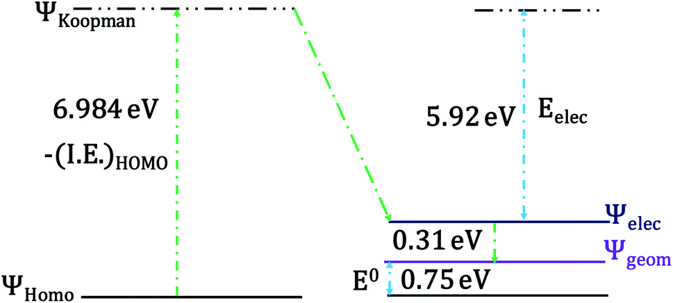 | ||
| Scheme 1 Schematic diagram of the electronically relaxed and the geometrically relaxed state after vertical ionization of the heme (S-oriented methionine). The energy associated with the Koopmans' state, geometric relaxation and electronic relaxation are indicated in the scheme. E0 is the theoretically determined reduction potential. | ||
The HOMO of the ferrous active site is the non-bonding dxy orbital as the dxz and dyz orbitals are stabilized by back bonding to the porphyrin ring π* orbitals. The energy of the ionization process depends on the energy of the HOMO and in this case (non-bonding HOMO) reflects the Zeff of the metal center. The Koopmans' state relaxes as the hole is allowed to redistribute within the molecule and without any change of geometry. The wavefunction of this state is obtained and the t2 hole now migrates to a dxz/yz orbital and it stabilized by covalent π donation of the porphyrin ligand. The energy of Koopmans' state for HtWT with S-oriented methionine was evaluated to be 6.984 eV, which is the negative ionization energy of the HOMO. The theoretical reduction potential in the gas phase was calculated from the difference of the optimization energy of ferric and ferrous HtWT and found to be 0.75 V. A change in geometry lowers the energy by a further 0.31 eV defined by the reorganization energy of the species. The summation of electronic and geometric relaxation along with the reduction potential reflects the energy of the Koopmans' state. Thus, stabilization by the electronic relaxation is 5.92 eV estimated from the difference. The large electronic relaxation leads to stabilization of the hole created upon oxidation and reduces the need for substantial geometric relaxation, which is key to lowering the λIS of the ET process. Similarly, large electronic relaxation was observed in Fe4S4 proteins which also have very low λ.98 The change of the ground state wavefunction of the hole created immediately after oxidation (without geometry change) and the final ground state wavefunction of the hole after geometric relaxation indicates a shift of electron density between different parts of the active site, which reflects the small changes of geometry associated with the process. For example, the wavefunction of the t2 hole in the HtWT model after ionization is more delocalized (on both Y-axis and X-axis, Fig. 16) than the wavefunction obtained after geometric relaxation where the hole is now localized mainly along the X-axis (plane containing peripheral 3CH3–8CH3). A substantial change in the extent of delocalization of the hole over the pyrrole rings during the geometric relaxation process automatically implies a higher λcal. Similarly, the hole created on oxidation of the Q64N mutant in its S-orientation shows re-orientation of the hole during geometric relaxation. Alternatively, the hole created in the case of Q64V mutant is already localized along the X-axis and does not change substantially during geometric relaxation, consistent with a smaller calculated λcal.
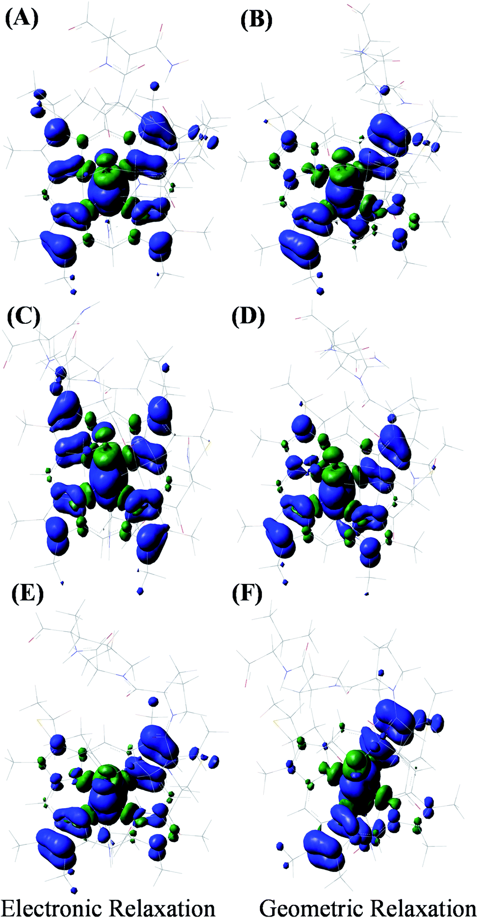 | ||
| Fig. 16 Spin density distribution of (A and B) HtWT (S-conformation form shown), (C and D) Q64N (S-conformation), and (E and F) Q64V (R-conformation) after immediate oxidation (electronic relaxation) and after the relaxation (geometric relaxation). Blue represents the majority α spin density and green represents β spin density. | ||
Discussion
Here, we demonstrate that the reorganization energies of redox-active species in solution can be determined conveniently using a dynamic electrochemical technique like RDE. The approach treats the electron transfer between the solution species and the electrode surface as an electrocatalytic reaction. The slopes of the K–L plots obtained in these cases agree with the expectations of a 1e− electron transfer reaction. Assuming that the electroactive area of the electrode remains constant with temperature, an Arrhenius-type treatment of the rate obtained at different temperatures allows determination of total reorganization energy (λTotal). The reorganization energy so determined is comprised of both inner-sphere and outer-sphere contributions and the contribution of the electrode surface to λTotal should be minimal.23 The approach is calibrated with two well-characterized redox systems; [Fe(CN)6]3−/4− (inorganic complex) and b-cyt c (electron transfer protein). The values determined here compare very well with literature values, demonstrating that analysis of RDE data as described herein is a convenient way of determining λTotal of electroactive species in solution. The reorganization energy is also determined for b-cyt c attached electrostatically to an electrode using chronoamperometry and cyclic voltammetry (using Laviron's method). The reorganization energy so determined can be expected to have substantially lower outer-sphere contribution from changes in solvation relative to the b-cyt c present in solution. Excellent agreement between the value of reorganization energy for the immobilized proteins is observed between these two complementary techniques. Furthermore, the reorganization energy determined using these two methods is almost half of that determined by RDE method for freely diffusing protein, and is very close to past literature reports on reorganization energy of horse-heart cyt c determined by electrochemical methods.22,30 Thus, within some approximation, the chronoamperometry and Laviron's methods when applied to cyt c adsorbed on the modified electrodes reflects the λIS + λP of the protein (please note that, λSolv is always present, but its contribution is very small relative to the same for b-cyt c freely diffusing in solution).These approaches are extended to understand the effect of mutation of the Q64 residue in Ht cyt c on reorganization energy and on electron transfer kinetics. The λIS + λP (λCA) of HtWT determined from the electrochemical techniques used in this study is ∼0.3 eV (Table 1, row 4) more than that of b-cyt c determined using the same approach. The estimated λIS + λP from the electrochemical data on these proteins indicate that the difference in the λTotal is entirely derived from differences in their respective λIS + λP (Table 1, row 4, 5 and 6). The λTotal values for the Q64V and Q64N mutant are 0.16 eV and 0.10 eV lower than that of HtWT, respectively. Note that these differences between the λTotal in these proteins are well outside of the error of the measurement. The difference in the λIS + λP of HtWT and HtQ64V is ∼0.16–0.12 eV, which suggests that the major contribution to the difference in the λTotal of the two (0.16 eV) seems to originate from the λIS + λP contribution to λTotal. On the contrary, the λIS + λP of HtWT and Q64N are very similar, suggesting that the 0.10 eV difference in λTotal is derived from differences in their respective λOS contribution to λTotal. Notably, NMR analysis of the solution structures of these proteins indicates that the side chain of Q64 is positioned to interact with solvent in HtWT, whereas the N64 side chain in the Q64N variant is buried and interacting with the heme axial Met.32–34 This structural difference is a possible basis for this difference in outer-sphere reorganization energy.
DFT calculations shed light on the factors that contribute to the differences in λIS + λP between the HtWT, Q64V and Q64N proteins. The calculated λIS (λcal) of the S-state is generally 0.02–0.05 eV higher than that of the R-state for each variant. The HtWT protein is known to exist in a dynamic equilibrium between the two states in solution at room temperature. Thus, an average of the two λcal of 0.325 eV is a reasonable approximation. The Q64N mutant resides dominantly in its S-conformation which is computed to have a λcal of 0.29 eV which is quite close to the average λcal computed for the HtWT consistent with the experimental data. The Q64V mutant, on the other hand, has a λcal of 0.21 eV which is about 0.11 eV lower than that of HtWT. This difference has minimal contribution from the methionine orientation (0.02–0.05 eV). Rather, the difference stems from the single mutation of the Q64 residue to V.
The optimized geometry indicates that the Q64 residue is poised over the heme cofactor with short contacts (<3.5 Å). The redox active molecular orbital (RAMO) of HtWT is more delocalized than that of HtQ64V as the RAMO in the later is localized more along the X-axis with very minor contribution from the pyrroles along the Y-axis (Fig. 16E and F). The presence of the glutamine dipole close to the heme polarizes the electron density and directs the partial localization of the hole along the Y-axis (Fig. 16A and B). This increases the λcal of the redox process in the HtWT active site. However, the ET rates of HtWT with greater λIS + λP are greater than those of the Q64V mutant which has a lower λIS + λP. Thus, the HAB must be enabling faster ET in HtWT despite having higher λIS + λP. Greater delocalization of the RAMO should enhance the electron transfer matrix HAB. Note that in the case the Q64 residue is oriented to the outside of the protein, we propose that water may enter the distal site and have a similar effect. The 5CH3 group along the Y-axis is closest to the protein surface and is thus expected to be important for the ET pathway. Thus, having the RAMO delocalized along the Y-axis where the 5CH3 is oriented should increase the HAB at the cost of a greater λIS + λP.
In fact, the HAB can be estimated from the ET rates of these proteins and corresponding λ values (Table 2) using the Marcus equation (eqn (1)) with an overpotential (driving force for ET) of 113 mV. The estimated HAB ∼1 cm−1 represents the ET between the electrode covered SAM and the cyt c and the corresponding tunnelling distance is expected to be 13–14 Å based on the Winkler and Gray correlation.99 This agrees very well with the expected distance of the linker carboxylate thiol from the electrode (Fig. S48†). The estimated HAB for the HtWT is four times greater than that of Q64V mutant. Thus, while the λTotal of the HtWT is ∼0.15 eV higher than that of Q64V mutant, the HAB is four times higher. From the Marcus equation (eqn (1)) one can evaluate the relative effect of λTotal and HAB on the ET rate. For simplicity, assuming the driving force for ET to be zero as in self-exchange ET reactions, at room temperature, a ∼0.15 eV greater λTotal will reduce the ET rate by a factor of 2.2. However, the rate is more sensitive to HAB, and is expected to increase linearly with the square of HAB. The 4-fold higher HAB in HtWT (Table 2) relative to HtQ64V would result in a 16-fold enhancement in the rate. Thus, although the HtWT has a higher λTotal resulting from the greater polarization of the RAMO, the higher RAMO delocalization in HtWT relative to the two mutants yields a larger HAB and overall, faster self-exchange ET rate (Fig. 17).
| Mutants | H AB (cm−1) η = 113 mV @ 298 K | λ Total (eV) |
|---|---|---|
| HtWT | 0.84 ± 0.04 | 1.36 ± 0.03 |
| HtQ64V | 0.19 ± 0.01 | 1.20 ± 0.01 |
| HtQ64N | 0.31 ± 0.01 | 1.26 ± 0.02 |
 | ||
| Fig. 17 LUMO of (A) HtWT (modelled here with S-oriented methionine), (B) Q64V (R-oriented methionine) and (C) Q64N (S-oriented methionine) mutant. | ||
Conclusion
In conclusion, we have used dynamic electrochemical techniques for the convenient measurement of the total reorganization energies (λTotal) of redox-active species in solution. The value of reorganization energy thus obtained represents the combination of both the inner-sphere and outer-sphere reorganization energy. This method has been calibrated with two well-characterized redox systems ([Fe(CN)6]3− and b-cyt c). The determined reorganization energy values agree well with previous reports, demonstrating that RDE is a suitable way to determine λTotal of any electroactive species in solution. The reorganization energy is also determined by electrostatically attaching cyt c to a modified Au electrode and probing using both chronoamperometry and cyclic voltammetry. These two complementary techniques provide good agreement between the experimentally determined reorganization energy. Values of reorganization energy determined using these techniques are almost half of those determined using the RDE method, consistent with greater contribution of λOS to the latter and are very close to the previous literature reports. These three electrochemical techniques are then extended to determine the reorganization energy of cyt c552 from Hydrogenobacter thermophilus (HtWT) (with a fluxional axial methionine (Met) axial ligand) and its two site directed mutants (in which the orientation of the Met group is fixed). We have seen that although HtQ64V shows a lower λ value relative to HtWT, the rate of ET between a modified Au electrode and the protein is greater in the case of HtWT. DFT calculations shed light on the factors contributing to these differences in reorganization energies and in ET rates in these proteins. The RAMO of HtWT is more delocalized than that of HtQ64V, which yields a 4.5-fold increase in the corresponding HAB value for HtWT. This larger HAB value is the key factor responsible for the larger kET for HtWT despite its greater reorganization energy relative to the HtQ64V mutant. In summary, these results yield detailed insights into contributions of cyt c active-site residues to reorganization energy and HAB, key factors controlling ET rates in biology.Data availability
Additional electrochemical data and optimized coordinates are available in the ESI file.†Author contributions
A. D. and K. L. B. designed the research. S. C. and M. M. performed the electrochemical experiments. M. M. and B. K. synthesized the HtWT and its mutants. S. C. performed the theoretical calculations. S. C., M. M., A. D. and K. L. B. analyzed the data and S. C., M. M., A. D, and K. L. B. wrote the manuscript. All authors provided feedback on the manuscript.Conflicts of interest
The authors declare no competing financial interest.Acknowledgements
This work was supported by the Department of Science and Technology Grant (SERB STR/2019/000081), DST/TMD/HFC/2K18/90(G). S. C. and M. M. acknowledge the IACS IntPCS program.References
- H. B. Gray and J. R. Winkler, Electron Transfer in Proteins, Annu. Rev. Biochem., 1996, 65(1), 537–561 CrossRef CAS PubMed.
- A. Warshel, A. K. Churg and R. Huber, Converting structural changes upon oxidation of cytochrome c to electrostatic reorganization energy, J. Mol. Biol., 1983, 168(3), 693–697 CrossRef CAS PubMed.
- R. S. Farid, C. C. Moser and P. Leslie Dutton, Electron transfer in proteins, Curr. Opin. Struct. Biol., 1993, 3(2), 225–233 CrossRef CAS.
- S. M. Andrew, K. A. Thomasson and S. H. Northrup, Simulation of electron-transfer self-exchange in cytochromes c and b5, J. Am. Chem. Soc., 1993, 115(13), 5516–5521 CrossRef CAS.
- J. Liu, S. Chakraborty, P. Hosseinzadeh, Y. Yu, S. Tian, I. Petrik, A. Bhagi and Y. Lu, Metalloproteins Containing Cytochrome, Iron–Sulfur, or Copper Redox Centers, Chem. Rev., 2014, 114(8), 4366–4469 CrossRef CAS PubMed.
- S. Terrettaz, J. Cheng, C. J. Miller and R. D. Guiles, Kinetic Parameters for Cytochrome c via Insulated Electrode Voltammetry, J. Am. Chem. Soc., 1996, 118(33), 7857–7858 CrossRef CAS.
- R. H. Holm, P. Kennepohl and E. I. Solomon, Structural and Functional Aspects of Metal Sites in Biology, Chem. Rev., 1996, 96(7), 2239–2314 CrossRef CAS PubMed.
- H. Shafiey, H. Ghourchian and N. Mogharrab, How does reorganization energy change upon protein unfolding? Monitoring the structural perturbations in the heme cavity of cytochrome c, Biophys. Chem., 2008, 134(3), 225–231 CrossRef CAS PubMed.
- H. Liu, H. Yamamoto, J. Wei and D. H. Waldeck, Control of the Electron Transfer Rate between Cytochrome c and Gold Electrodes by the Manipulation of the Electrode's Hydrogen Bonding Character, Langmuir, 2003, 19(6), 2378–2387 CrossRef CAS.
- R. A. Marcus and N. Sutin, Electron transfers in chemistry and biology, Biochim. Biophys. Acta, Rev. Bioenerg., 1985, 811(3), 265–322 CrossRef CAS.
- J. R. Winkler, J. Di Bilio Angel, N. A. Farrow, J. H. Richards and H. B. Gray, Electron tunneling in biological molecules, Pure Appl. Chem., 1999, 71, 1753 CAS.
- X. Amashukeli, N. E. Gruhn, D. L. Lichtenberger, J. R. Winkler and H. B. Gray, Inner-Sphere Electron-Transfer Reorganization Energies of Zinc Porphyrins, J. Am. Chem. Soc., 2004, 126(47), 15566–15571 CrossRef CAS PubMed.
- R. A. Marcus, Chemical and Electrochemical Electron-Transfer Theory, Annu. Rev. Phys. Chem., 1964, 15(1), 155–196 CrossRef CAS.
- E. Sigfridsson, M. H. M. Olsson and U. Ryde, A Comparison of the Inner-Sphere Reorganization Energies of Cytochromes, Iron–Sulfur Clusters, and Blue Copper Proteins, J. Phys. Chem. B, 2001, 105(23), 5546–5552 CrossRef CAS.
- S. Bandyopadhyay, A. Rana, K. Mittra, S. Samanta, K. Sengupta and A. Dey, Effect of Axial Ligand, Spin State, and Hydrogen Bonding on the Inner-Sphere Reorganization Energies of Functional Models of Cytochrome P450, Inorg. Chem., 2014, 53(19), 10150–10158 CrossRef CAS PubMed.
- J. I. Blankman, N. Shahzad, B. Dangi, C. J. Miller and R. D. Guiles, Voltammetric Probes of Cytochrome Electroreactivity: The Effect of the Protein Matrix on Outer-Sphere Reorganization Energy and Electronic Coupling Probed through Comparisons with the Behavior of Porphyrin Complexes, Biochemistry, 2000, 39(48), 14799–14805 CrossRef CAS PubMed.
- M. Fedurco, Redox reactions of heme-containing metalloproteins: dynamic effects of self-assembled monolayers on thermodynamics and kinetics of cytochrome c electron-transfer reactions, Coord. Chem. Rev., 2000, 209(1), 263–331 CrossRef CAS.
- A. B. Myers, Resonance Raman Intensities and Charge-Transfer Reorganization Energies, Chem. Rev., 1996, 96(3), 911–926 CrossRef CAS PubMed.
- L. Hu, M. Farrokhnia, J. Heimdal, S. Shleev, L. Rulíšek and U. Ryde, Reorganization Energy for Internal Electron Transfer in Multicopper Oxidases, J. Phys. Chem. B, 2011, 115(45), 13111–13126 CrossRef CAS PubMed.
- K. A. Sharp, Calculation of Electron Transfer Reorganization Energies Using the Finite Difference Poisson-Boltzmann Model, Biophys. J., 1998, 74(3), 1241–1250 CrossRef CAS PubMed.
- J. E. Frew and H. A. O. Hill, Direct and indirect electron transfer between electrodes and redox proteins, Eur. J. Biochem., 1988, 172(2), 261–269 CrossRef CAS PubMed.
- J. Cheng, S. Terrettaz, J. I. Blankman, C. J. Miller, B. Dangi and R. D. Guiles, Electrochemical Comparison of Heme Proteins by Insulated Electrode Voltammetry, Isr. J. Chem., 1997, 37(2–3), 259–266 CrossRef CAS.
- S. Song, R. A. Clark, E. F. Bowden and M. J. Tarlov, Characterization of cytochrome c/alkanethiolate structures prepared by self-assembly on gold, J. Phys. Chem., 1993, 97(24), 6564–6572 CrossRef CAS.
- M. J. Tarlov and E. F. Bowden, Electron-transfer reaction of cytochrome c adsorbed on carboxylic acid terminated alkanethiol monolayer electrodes, J. Am. Chem. Soc., 1991, 113(5), 1847–1849 CrossRef CAS.
- D. H. Murgida and P. Hildebrandt, Electrostatic-Field Dependent Activation Energies Modulate Electron Transfer of Cytochrome c, J. Phys. Chem. B, 2002, 106(49), 12814–12819 CrossRef CAS.
- C. C. Moser, C. C. Page and P. L. Dutton, Darwin at the molecular scale: selection and variance in electron tunnelling proteins including cytochrome c oxidase, Philos. Trans. R. Soc., B, 2006, 361(1472), 1295–1305 CrossRef CAS PubMed.
- G. Basu, A. Kitao, A. Kuki and N. Go, Protein Electron Transfer Reorganization Energy Spectrum from Normal Mode Analysis. 2. Application to Ru-Modified Cytochrome c, J. Phys. Chem. B, 1998, 102(11), 2085–2094 CrossRef CAS.
- J. Blumberger and G. Lamoureux, Reorganization free energies and quantum corrections for a model electron self-exchange reaction: comparison of polarizable and non-polarizable solvent models, Mol. Phys., 2008, 106(12–13), 1597–1611 CrossRef CAS.
- A. K. Churg and A. Warshel, Control of the redox potential of cytochrome and microscopic dielectric effects in proteins, Biochemistry, 1986, 25(7), 1675–1681 CrossRef CAS PubMed.
- I. Muegge, P. X. Qi, A. J. Wand, Z. T. Chu and A. Warshel, The Reorganization Energy of Cytochrome c Revisited, J. Phys. Chem. B, 1997, 101(5), 825–836 CrossRef CAS.
- D. W. Dixon, X. Hong, S. E. Woehler, A. G. Mauk and B. P. Sishta, Electron-transfer self-exchange kinetics of cytochrome b5, J. Am. Chem. Soc., 1990, 112(3), 1082–1088 CrossRef CAS.
- X. Wen and K. L. Bren, Suppression of Axial Methionine Fluxion in Hydrogenobacter thermophilus Gln64Asn Cytochrome c552, Biochemistry, 2005, 44(13), 5225–5233 CrossRef CAS PubMed.
- L. Zhong, X. Wen, T. M. Rabinowitz, B. S. Russell, E. F. Karan and K. L. Bren, Heme axial methionine fluxionality in Hydrogenobacter thermophilus cytochrome c552, Proc. Natl. Acad. Sci. U. S. A., 2004, 101(23), 8637 CrossRef CAS PubMed.
- M. D. Liptak, X. Wen and K. L. Bren, NMR and DFT Investigation of Heme Ruffling: Functional Implications for Cytochrome c, J. Am. Chem. Soc., 2010, 132(28), 9753–9763 CrossRef CAS PubMed.
- K. L. Bren, Going with the Electron Flow: Heme Electronic Structure and Electron Transfer in Cytochrome c, Isr. J. Chem., 2016, 56(9–10), 693–704 CrossRef CAS.
- R. Kaur and K. L. Bren, Redox State Dependence of Axial Ligand Dynamics in Nitrosomonas europaea Cytochrome c552, J. Phys. Chem. B, 2013, 117(49), 15720–15728 CrossRef CAS PubMed.
- A. L. Eckermann, D. J. Feld, J. A. Shaw and T. J. Meade, Electrochemistry of redox-active self-assembled monolayers, Coord. Chem. Rev., 2010, 254(15), 1769–1802 CrossRef CAS PubMed.
- R. J. Forster and L. R. Faulkner, Electrochemistry of Spontaneously Adsorbed Monolayers. Equilibrium Properties and Fundamental Electron Transfer Characteristics, J. Am. Chem. Soc., 1994, 116(12), 5444–5452 CrossRef CAS.
- H. O. Finklea and D. D. Hanshew, Electron-transfer kinetics in organized thiol monolayers with attached pentaammine(pyridine)ruthenium redox centers, J. Am. Chem. Soc., 1992, 114(9), 3173–3181 CrossRef CAS.
- S. Mukherjee, S. Bandyopadhyay and A. Dey, Tuning the apparent formal potential of covalently attached ferrocene using SAM bearing ionizable COOH groups, Electrochim. Acta, 2013, 108, 624–633 CrossRef CAS.
- R. Meunier-Prest, G. Legay, S. Raveau, N. Chiffot and E. Finot, Potential-assisted deposition of mixed alkanethiol self-assembled monolayers, Electrochim. Acta, 2010, 55(8), 2712–2720 CrossRef CAS.
- J. Hasegawa, T. Yoshida, T. Yamazaki, Y. Sambongi, Y. Yu, Y. Igarashi, T. Kodama, K.-i. Yamazaki, Y. Kyogoku and Y. Kobayashi, Solution Structure of Thermostable Cytochrome c-552 from Hydrogenobacter thermophilus Determined by 1H-NMR Spectroscopy, Biochemistry, 1998, 37(27), 9641–9649 CrossRef CAS PubMed.
- M. J. Frisch, G. W. Trucks, H. B. Schlegel, G. E. Scuseria, M. A. Robb, J. R. Cheeseman, J. A. Montgomery Jr, T. Vreven, K. N. Kudin, J. C. Burant, J. M. Millam, S. S. Iyengar, J. Tomasi, V. Barone, B. Mennucci, M. Cossi, G. Scalmani, N. Rega, G. A. Petersson, H. Nakatsuji, M. Hada, M. Ehara, K. Toyota, R. Fukuda, J. Hasegawa, M. Ishida, T. Nakajima, Y. Honda, O. Kitao, H. Nakai, M. Klene, X. Li, J. E. Knox, H. P. Hratchian, J. B. Cross, V. Bakken, C. Adamo, J. Jaramillo, R. Gomperts, R. E. Stratmann, O. Yazyev, A. J. Austin, R. Cammi, C. Pomelli, J. W. Ochterski, P. Y. Ayala, K. Morokuma, G. A. Voth, P. Salvador, J. J. Dannenberg, V. G. Zakrzewski, S. Dapprich, A. D. Daniels, M. C. Strain, O. Farkas, D. K. Malick, A. D. Rabuck, K. Raghavachari, J. B. Foresman, J. V. Ortiz, Q. Cui, A. G. Baboul, S. Clifford, J. Cioslowski, B. B. Stefanov, G. Liu, A. Liashenko, P. Piskorz, I. Komaromi, R. L. Martin, D. J. Fox, T. Keith, M. A. Al-Laham, C. Y. Peng, A. Nanayakkara, M. Challacombe, P. M. W. Gill, B. Johnson, W. Chen, M. W. Wong, C. Gonzalez, and J. A. Pople, Gaussian, Inc., Wallingford CT, 2004.
- R. Krishnan, J. S. Binkley, R. Seeger and J. A. Pople, Self-consistent molecular orbital methods. XX. A basis set for correlated wave functions, J. Chem. Phys., 1980, 72(1), 650–654 CrossRef CAS.
- A. D. McLean and G. S. Chandler, Contracted Gaussian basis sets for molecular calculations. I. Second row atoms, Z=11–18, J. Chem. Phys., 1980, 72(10), 5639–5648 CrossRef CAS.
- X. Jiang, Z. Futera and J. Blumberger, Ergodicity-Breaking in Thermal Biological Electron Transfer? Cytochrome C Revisited, J. Phys. Chem. B, 2019, 123(35), 7588–7598 CrossRef CAS PubMed.
- X. Jiang, B. Burger, F. Gajdos, C. Bortolotti, Z. Futera, M. Breuer and J. Blumberger, Kinetics of trifurcated electron flow in the decaheme bacterial proteins MtrC and MtrF, Proc. Natl. Acad. Sci. U. S. A., 2019, 116(9), 3425 CrossRef CAS PubMed.
- C. A. Bortolotti, M. E. Siwko, E. Castellini, A. Ranieri, M. Sola and S. Corni, The Reorganization Energy in Cytochrome c is Controlled by the Accessibility of the Heme to the Solvent, J. Phys. Chem. Lett., 2011, 2(14), 1761–1765 CrossRef CAS.
- C. A. Bortolotti, A. Amadei, M. Aschi, M. Borsari, S. Corni, M. Sola and I. Daidone, The Reversible Opening of Water Channels in Cytochrome c Modulates the Heme Iron Reduction Potential, J. Am. Chem. Soc., 2012, 134(33), 13670–13678 CrossRef CAS PubMed.
- J. Blumberger, Recent Advances in the Theory and Molecular Simulation of Biological Electron Transfer Reactions, Chem. Rev., 2015, 115(20), 11191–11238 CrossRef CAS PubMed.
- A. J. Bard and L. R. Faulkner, Electrochemical Methods: Fundamentals and Applications. Wiley, 2nd edn, 2000 Search PubMed.
- S. M. Barnett, K. I. Goldberg and J. M. Mayer, A soluble copper–bipyridine water-oxidation electrocatalyst, Nat. Chem., 2012, 4, 498 CrossRef CAS PubMed.
- W. Schöfberger, F. Faschinger, S. Chattopadhyay, S. Bhakta, B. Mondal, J. A. A. W. Elemans, S. Müllegger, S. Tebi, R. Koch, F. Klappenberger, M. Paszkiewicz, J. V. Barth, E. Rauls, H. Aldahhak, W. G. Schmidt and A. Dey, A Bifunctional Electrocatalyst for Oxygen Evolution and Oxygen Reduction Reactions in Water, Angew. Chem., Int. Ed., 2016, 55(7), 2350–2355 CrossRef PubMed.
- A. Purwidyantri, C.-H. Chen, L.-Y. Chen, C.-C. Chen, J.-D. Luo, C.-C. Chiou, Y.-C. Tian, C.-Y. Lin, C.-M. Yang, H.-C. Lai and C.-S. Lai, Speckled ZnO Nanograss Electrochemical Sensor for Staphylococcus epidermidis Detection, J. Electrochem. Soc., 2017, 164(6), B205–B211 CrossRef CAS.
- J. F. Smalley, S. W. Feldberg, C. E. D. Chidsey, M. R. Linford, M. D. Newton and Y.-P. Liu, The Kinetics of Electron Transfer Through Ferrocene-Terminated Alkanethiol Monolayers on Gold, J. Phys. Chem., 1995, 99(35), 13141–13149 CrossRef CAS.
- W.-c. Park and H.-G. Hong, Determination of Reorganization Energy from the Temperature Dependence of Electron Transfer Rate Constant for Hydroquinone-tethered Self-assembled Monolayers (SAMs), Bull. Korean Chem. Soc., 2006, 27(3), 381–385 CrossRef CAS.
- R. Seidel, S. Thürmer, J. Moens, P. Geerlings, J. Blumberger and B. Winter, Valence Photoemission Spectra of Aqueous Fe2+/3+ and [Fe(CN)6]4−/3− and Their Interpretation by DFT Calculations, J. Phys. Chem. B, 2011, 115(40), 11671–11677 CrossRef CAS PubMed.
- M. C. Thielges, J. Zimmermann, P. E. Dawson and F. E. Romesberg, The Determinants of Stability and Folding in Evolutionarily Diverged Cytochromes c, J. Mol. Biol., 2009, 388(1), 159–167 CrossRef CAS PubMed.
- X. Chen, H.-Y. Long, W.-L. Wu and Z.-S. Yang, Direct electrochemical behavior of cytochrome c on sodium dodecyl sulfate modified electrode and its application to nitric oxide biosensor, Thin Solid Films, 2009, 517(8), 2787–2791 CrossRef CAS.
- Y. Zhou, J. Zhi, Y. Zou, W. Zhang and S.-T. Lee, Direct Electrochemistry and Electrocatalytic Activity of Cytochrome c Covalently Immobilized on a Boron-Doped Nanocrystalline Diamond Electrode, Anal. Chem., 2008, 80(11), 4141–4146 CrossRef CAS PubMed.
- S. López-Bernabeu, F. Huerta, E. Morallón and F. Montilla, Direct Electron Transfer to Cytochrome c Induced by a Conducting Polymer, J. Phys. Chem. C, 2017, 121(29), 15870–15879 CrossRef.
- H. Yue and D. H. Waldeck, Understanding interfacial electron transfer to monolayer protein assemblies, Curr. Opin. Solid State Mater. Sci., 2005, 9(1), 28–36 CrossRef CAS.
- J. Petrović, R. A. Clark, H. Yue, D. H. Waldeck and E. F. Bowden, Impact of Surface Immobilization and Solution Ionic Strength on the Formal Potential of Immobilized Cytochrome c, Langmuir, 2005, 21(14), 6308–6316 CrossRef PubMed.
- H. Yue, D. Khoshtariya, D. H. Waldeck, J. Grochol, P. Hildebrandt and D. H. Murgida, On the Electron Transfer Mechanism Between Cytochrome c and Metal Electrodes. Evidence for Dynamic Control at Short Distances, J. Phys. Chem. B, 2006, 110(40), 19906–19913 CrossRef CAS PubMed.
- J. Wei, H. Liu, A. R. Dick, H. Yamamoto, Y. He and D. H. Waldeck, Direct Wiring of Cytochrome c's Heme Unit to an Electrode: Electrochemical Studies, J. Am. Chem. Soc., 2002, 124(32), 9591–9599 CrossRef CAS PubMed.
- M. Graf, R. G. García and H. Wätzig, Protein adsorption in fused-silica and polyacrylamide-coated capillaries, Electrophoresis, 2005, 26(12), 2409–2417 CrossRef CAS PubMed.
- J. J. Wendoloski, J. B. Matthew, P. C. Weber and F. R. Salemme, Molecular dynamics of a cytochrome c-cytochrome b5 electron transfer complex, Science, 1987, 238(4828), 794 CrossRef CAS PubMed.
- M. R. Mauk, A. G. Mauk, P. C. Weber and J. B. Matthew, Electrostatic analysis of the interaction of cytochrome c with native and dimethyl ester heme-substituted cytochrome b5, Biochemistry, 1986, 25(22), 7085–7091 CrossRef CAS PubMed.
- T. L. Poulos and J. Kraut, A hypothetical model of the cytochrome c peroxidase . cytochrome c electron transfer complex, J. Biol. Chem., 1980, 255(21), 10322–10330 CrossRef CAS.
- D. A. Paggi, D. F. Martín, A. Kranich, P. Hildebrandt, M. A. Martí and D. H. Murgida, Computer simulation and SERR detection of cytochrome c dynamics at SAM-coated electrodes, Electrochim. Acta, 2009, 54(22), 4963–4970 CrossRef CAS.
- A. Kranich, H. K. Ly, P. Hildebrandt and D. H. Murgida, Direct Observation of the Gating Step in Protein Electron Transfer: Electric-Field-Controlled Protein Dynamics, J. Am. Chem. Soc., 2008, 130(30), 9844–9848 CrossRef CAS PubMed.
- D. H. Murgida and P. Hildebrandt, Electron-Transfer Processes of Cytochrome c at Interfaces. New Insights by Surface-Enhanced Resonance Raman Spectroscopy, Acc. Chem. Res., 2004, 37(11), 854–861 CrossRef CAS PubMed.
- D. H. Murgida and P. Hildebrandt, Heterogeneous Electron Transfer of Cytochrome c on Coated Silver Electrodes. Electric Field Effects on Structure and Redox Potential, J. Phys. Chem. B, 2001, 105(8), 1578–1586 CrossRef CAS.
- C. P. Smith and H. S. White, Theory of the interfacial potential distribution and reversible voltammetric response of electrodes coated with electroactive molecular films, Anal. Chem., 1992, 64(20), 2398–2405 CrossRef CAS PubMed.
- H. Wackerbarth and P. Hildebrandt, Redox and Conformational Equilibria and Dynamics of Cytochrome c at High Electric Fields, ChemPhysChem, 2003, 4(7), 714–724 CrossRef CAS PubMed.
- J. Wei, H. Liu, D. E. Khoshtariya, H. Yamamoto, A. Dick and D. H. Waldeck, Electron-Transfer Dynamics of Cytochrome C: A Change in the Reaction Mechanism with Distance, Angew. Chem., Int. Ed., 2002, 41(24), 4700–4703 CrossRef CAS PubMed.
- D. H. Murgida and P. Hildebrandt, Proton-Coupled Electron Transfer of Cytochrome c, J. Am. Chem. Soc., 2001, 123(17), 4062–4068 CrossRef CAS PubMed.
- S. Chattopadhyay, S. Bandyopadhyay and A. Dey, Kinetic Isotope Effects on Electron Transfer Across Self-Assembled Monolayers on Gold, Inorg. Chem., 2021, 60(2), 597–605 CrossRef CAS PubMed.
- M. E. Young, P. A. Carroad and R. L. Bell, Estimation of diffusion coefficients of proteins, Biotechnol. Bioeng., 1980, 22(5), 947–955 CrossRef CAS.
- K. C. Cho, K. M. Ng, C. L. Choy and C. M. Che, Electron transfer between cytochrome c and metalloporphyrins at high exothermicities, Chem. Phys. Lett., 1986, 129(5), 521–525 CrossRef CAS.
- E. Cheung, K. Taylor, J. A. Kornblatt, A. M. English, G. McLendon and J. R. Miller, Direct measurements of intramolecular electron transfer rates between cytochrome c and cytochrome c peroxidase: effects of exothermicity and primary sequence on rate, Proc. Natl. Acad. Sci. U. S. A., 1986, 83(5), 1330 CrossRef CAS PubMed.
- G. McLendon, Long-distance electron transfer in proteins and model systems, Acc. Chem. Res., 1988, 21(4), 160–167 CrossRef CAS.
- D. G. Nocera, J. R. Winkler, K. M. Yocom, E. Bordignon and H. B. Gray, Kinetics of intermolecular and intramolecular electron transfer from ruthenium(II) complexes to ferricytochrome c, J. Am. Chem. Soc., 1984, 106(18), 5145–5150 CrossRef CAS.
- D. E. Khoshtariya, J. Wei, H. Liu, H. Yue and D. H. Waldeck, Charge-Transfer Mechanism for Cytochrome c Adsorbed on Nanometer Thick Films. Distinguishing Frictional Control from Conformational Gating, J. Am. Chem. Soc., 2003, 125(25), 7704–7714 CrossRef CAS PubMed.
- A. K. Churg, R. M. Weiss, A. Warshel and T. Takano, On the action of cytochrome c: correlating geometry changes upon oxidation with activation energies of electron transfer, J. Phys. Chem., 1983, 87(10), 1683–1694 CrossRef CAS.
- T. J. Meade, H. B. Gray and J. R. Winkler, Driving-force effects on the rate of long-range electron transfer in ruthenium-modified cytochrome c, J. Am. Chem. Soc., 1989, 111(12), 4353–4356 CrossRef CAS.
- J. S. Zhou and M. A. J. Rodgers, Driving force dependence of rate constants of electron transfer within cytochrome c and uroporphyrin complexes, J. Am. Chem. Soc., 1991, 113(20), 7728–7734 CrossRef CAS.
- A. J. Di Bilio, M. G. Hill, N. Bonander, B. G. Karlsson, R. M. Villahermosa, B. G. Malmström, J. R. Winkler and H. B. Gray, Reorganization Energy of Blue Copper: Effects of Temperature and Driving Force on the Rates of Electron Transfer in Ruthenium- and Osmium-Modified Azurins, J. Am. Chem. Soc., 1997, 119(41), 9921–9922 CrossRef CAS.
- M. Dinpajooh, D. R. Martin and D. V. Matyushov, Polarizability of the active site of cytochrome c reduces the activation barrier for electron transfer, Sci. Rep., 2016, 6(1), 28152 CrossRef CAS PubMed.
- T. M. Saccucci and J. F. Rusling, Modeling Square-Wave Voltammetry of Thin Protein Films Using Marcus Theory, J. Phys. Chem. B, 2001, 105(26), 6142–6147 CrossRef CAS.
- C. E. D. Chidsey, Free Energy and Temperature Dependence of Electron Transfer at the Metal-Electrolyte Interface, Science, 1991, 251(4996), 919 CrossRef CAS PubMed.
- H. Khoa Ly, N. Wisitruangsakul, M. Sezer, J.-J. Feng, A. Kranich, I. M. Weidinger, I. Zebger, D. H. Murgida and P. Hildebrandt, Electric-field effects on the interfacial electron transfer and protein dynamics of cytochrome c, J. Electroanal. Chem., 2011, 660(2), 367–376 CrossRef CAS.
- H. Khoa Ly, M. Sezer, N. Wisitruangsakul, J.-J. Feng, A. Kranich, D. Millo, I. M. Weidinger, I. Zebger, D. H. Murgida and P. Hildebrandt, Surface-enhanced vibrational spectroscopy for probing transient interactions of proteins with biomimetic interfaces: electric field effects on structure, dynamics and function of cytochrome c, FEBS J., 2011, 278(9), 1382–1390 CrossRef PubMed.
- E. Laviron, General expression of the linear potential sweep voltammogram in the case of diffusionless electrochemical systems, J. Electroanal. Chem. Interfacial Electrochem., 1979, 101(1), 19–28 CrossRef CAS.
- S. D. Mhaske, M. Ray and S. Mazumdar, Covalent linkage of CYP101 with the electrode enhances the electrocatalytic activity of the enzyme: Vectorial electron transport from the electrode, Inorg. Chim. Acta, 2010, 363(12), 2804–2811 CrossRef CAS.
- P. Kennepohl and E. I. Solomon, Electronic Structure Contributions to Electron-Transfer Reactivity in Iron–Sulfur Active Sites: 1. Photoelectron Spectroscopic Determination of Electronic Relaxation, Inorg. Chem., 2003, 42(3), 679–688 CrossRef CAS PubMed.
- P. Kennepohl and E. I. Solomon, Electronic Structure Contributions to Electron-Transfer Reactivity in Iron–Sulfur Active Sites: 2. Reduction Potentials, Inorg. Chem., 2003, 42(3), 689–695 CrossRef CAS PubMed.
- A. Dey, T. Glaser, M. M. J. Couture, L. D. Eltis, R. H. Holm, B. Hedman, K. O. Hodgson and E. I. Solomon, Ligand K-Edge X-ray Absorption Spectroscopy of [Fe4S4]1+,2+,3+ Clusters: Changes in Bonding and Electronic Relaxation upon Redox, J. Am. Chem. Soc., 2004, 126(26), 8320–8328 CrossRef CAS PubMed.
- J. R. Winkler and H. B. Gray, Electron Flow through Metalloproteins, Chem. Rev., 2014, 114(7), 3369–3380 CrossRef CAS PubMed.
Footnote |
| † Electronic supplementary information (ESI) available. See DOI: 10.1039/d1sc02865k |
| This journal is © The Royal Society of Chemistry 2021 |