
 Open Access Article
 This Open Access Article is licensed under a Creative Commons Attribution-Non Commercial 3.0 Unported Licence
Long-range light-modulated charge transport across the molecular heterostructure doped protein biopolymers†
Somen
Mondal
 *ab,
Nandan
Ghorai
c,
Soumyadip
Bhunia
d,
Hirendra. N.
Ghosh
c and
Nadav
Amdursky
*a
*ab,
Nandan
Ghorai
c,
Soumyadip
Bhunia
d,
Hirendra. N.
Ghosh
c and
Nadav
Amdursky
*a
aSchulich Faculty of Chemistry, Technion – Israel Institute of Technology, Haifa 3200003, Israel. E-mail: s.mondal@marj.ictmumbai.edu.in; amdursky@technion.ac.il
bInstitute of Chemical Technology, Mumbai, Marathwada Campus, Jalna, Maharashtra 431 203, India
cInstitute of Nano Science and Technology, Mohali, Punjab 160064, India
dIndian Institute of Science Education and Research (IISER) Kolkata, Mohanpur, West Bengal 741246, India
First published on 18th May 2021
Abstract
Biological electron transfer (ET) across proteins is ubiquitous, such as the notable photosynthesis example, where light-induced charge separation takes place within the reaction center, followed by sequential ET via intramolecular cofactors within the protein. Far from biology, carbon dots (C-Dots) with their unique optoelectronic properties can be considered as game-changers for next-generation advanced technologies. Here, we use C-Dots for making heterostructure (HS) configurations by conjugating them to a natural ET mediator, the hemin molecule, thus making an electron donor–acceptor system. We show by transient absorption and emission spectroscopy that the rapid intramolecular charge separation happens following light excitation, which can be ascribed to an ultrafast electron and hole transfer (HT) from the C-Dot donor to the hemin acceptor. Upon integrating the HS into a protein matrix, we show that this HT within the HS configuration is 3.3 times faster compared to the same process in solution, indicating the active role of the protein in supporting the rapid light-induced long-range intermolecular charge separation. We further use impedance, electrochemical, and transient photocurrent measurements to show that the light-induced transient charge separation results in an enhanced ET and HT efficiency across the protein biopolymer. The charge conduction across our protein biopolymers, reaching nearly 0.01 S cm−1, along with the simplicity and low-cost of their formation promotes their use in a variety of optoelectronic devices, such as artificial photosynthesis, photo-responsive protonic–electronic transistors, and photodetectors.
Introduction
Electron transfer (ET) is a fundamental process of many biological metabolic cycles as well as optoelectronic devices.1–3 Nature utilizes proteins to directly transport electrons, most often across a biological membrane, for example, the ET chain reaction in the mitochondria during aerobic respiration or the light-induced ET during photosynthesis.4 The latter example consists of a light-induced formation of an exciton on the chromophore, followed by a rapid (few ps) charge separation process, whereas the excited electron undergoes a sequential ET process across several intramolecular cofactors within the photosystem protein. In the end, the hole is used for water oxidation and the formation of oxygen, while the electron reduces NADP+ for the formation of NADPH. Far from biology, (light-induced) ET is important in various applications, such as solar energy conversion, biosensing, molecular electronics, and many more.5–7 In addition to electrons as charge carriers, proton transport (PT) is also important in the above-mentioned biological processes, and this type of transport is being mediated by proteins as well. Recently, it has been established that biomaterials can act as good long-range proton conductors, e.g. polysaccharides, melanin pigments, and protein-based materials.8–11 Here, we utilize a protein-based biopolymer having PT capabilities,10,12 while acknowledging novel light-induced ET properties using a molecular doping approach,9 hence creating a bioderived mixed (opto-)electronic-protonic conductor.8,10The protein that we used here was bovine serum albumin (BSA), which was shown to form various types of biopolymers, such as electrospun mats.13,14 Due to the abundance of protonated amino acids of the BSA protein as well as the high water content in the BSA-based electrospun mats, they show a modest proton conductivity of ∼0.1 mS cm−1.10 In addition to the low cost and commercial availability of the BSA protein, it has one more important advantage where it can strongly bind to a wide array of molecules and even nanoparticles.15,16 In this context, it was shown that the BSA mats can bind to electron mediating heme molecules resulting in a superior ET across the mats,9,17 as well as C-Dots that were shown to induce superior PT across the mats.18 In here, we combine similar molecular dopants to form a C-Dot–hemin heterostructure (HS) that is being integrated into the protein-based matrix. In this way, we acknowledge the new hybrid protein-based biopolymer’s unique optoelectronic properties are due to the formation of a long-lived charge-separated state via exciton–exciton coupling;19 where the C-Dots act as the photosensitizer and a tethered hemin molecule (Fe-containing protoporphyrin) is the electron (hole) acceptor.
The use of C-Dots is gaining high momentum in recent years, and it is considered a replacement for the traditional semiconductor quantum dot due to its high aqueous solubility, easy functionalization, low toxicity, and chemical inertness.20–24 In terms of their ET properties, C-Dots have been used as both electron donors as well as electron acceptors.20,25–29 While we mainly use the C-Dot here as a photosensitizer, i.e., a light-induced electron donor, it is important to state that the type of C-Dots that we use here also acknowledges superior PT efficiency across the BSA mat.16 Besides being the electron acceptor, hemin is used here also as a molecular dopant for the BSA mat due to its strong binding affinity as well as a charge mediator capable of supporting long-range ET, whereas holes are the charge carriers.9,12 The BSA mat itself here is not just a passive polymeric matrix for the various charge transport processes, but it plays a crucial role in these processes. First, it supports the PT across the material, and second, it acts as an electronic passivation layer as well as a carrier transfer mediator to reduce the recombination between electrons and holes upon light illumination.30 Overall, our new hybrid material here exhibits a myriad of charge transfer processes: a light-induced short-range ET between the C-Dot and tethered hemin, a long-range ET across the BSA mat supported by the hemin dopant, and a long-range PT across the mat supported by the C-Dots and the protein itself. We use here steady-state and ultrafast spectroscopy, AC electrochemical impedance spectroscopy (EIS) and DC current–voltage (I–V) measurements to explore all of these processes and the interplay between them either in the form of a solvated HS or upon inserting the HS into the BSA mats.
Results
Characterization of the C-Dot and C-Dot–hemin HS
The C-Dot–hemin HS was prepared using the synthetic strategy displayed in Scheme 1. It is important to note here that our strategy results in several conjugations of hemin molecules to the many functional groups on the surface of the C-Dot, even though, the exact stoichiometry between the number of hemin copies on each C-Dot cannot be estimated. Our first validation for the C-Dot–hemin HS formation is confirmed by steady-state UV-Vis absorption (Fig. 1a). The absorption of C-Dots shows a peak at around 345 nm, which can be attributed to n–π* transitions. The absorbance of hemin consists of a typical Soret band, showing two peaks, one at about 360 nm (S′ band) and the other at 390 nm (S band), as well as Q-band peaks at around 500 and 600 nm, ascribed to the π–π* transitions.31 The absorption of the C-Dot–hemin HS shows intense absorbance at 360 nm and a shifted Q-band at 645 nm compared to that of free hemin. The differences in the optical absorption already indicate that the electronic interaction between hemin and the excitation band of C-Dots is quite strong in the C-Dot–hemin HS configuration. The broadening of the absorption in the C-Dot–hemin HS is a further indication of the formation of a charge transfer complex between C-Dots and hemin, which can be observed in the difference absorption spectrum (inset Fig. 1a). The morphology and surface functionalities of the synthesized C-Dots were determined using transmission electron microscopy (TEM) and FTIR, respectively. The TEM images of the synthesized C-Dots and C-Dot–hemin HS (Fig. 1b, S1a, and c in the ESI†) show a narrow size distribution with an average particle size of ∼4 nm for both C-Dots and the C-Dot–hemin HS (left inset Fig. 1b). Nevertheless, the HRTEM images and their associated inverse FFT images (inset Fig. 1b and S1a–d†) show a different interplanar spacing between the C-Dots and C-Dot–hemin HS of ∼0.21 nm and ∼0.36 nm, respectively. Our observed crystalline structure of the C-Dots with a calculated d spacing of ∼0.21 nm corresponds with the (100) lattice plane of C-Dots.32 The increase in interplanar spacing upon the formation of the HS is due to lattice strain generation in the new nanoparticle. The energy-dispersive spectra (EDS) elemental analysis confirms the presence of hemin (Fe ion) within the synthesized C-Dot–hemin HS (Fig. S1e†). The FTIR spectrum of the C-Dots (Fig. S2†) exhibits a stretching at 3160–3400 cm−1, which can be assigned to the hydroxy (–OH) and amine (–NH) groups, as well as a carboxylic group (–COOH) stretching at 1635 cm−1. The FTIR spectrum of the C-Dot–hemin HS (Fig. S2†) confirms the formation of the complex by exhibiting intense peaks at ∼1630 and 1508 cm−1, corresponding to amide-I (–C![[double bond, length as m-dash]](https://www.rsc.org/images/entities/char_e001.gif) O stretching) and amide-II (–C–N stretching and –N–H bending), while also including the C-Dot features at 3160–3400 cm−1 as described above. Moreover, the observed 10 cm−1 shift of amide-II (–C–N stretching and –N–H bending) stretching (1518 cm−1) after the conjugation of hemin with the C-Dot further supports the formation of the HS.
O stretching) and amide-II (–C–N stretching and –N–H bending), while also including the C-Dot features at 3160–3400 cm−1 as described above. Moreover, the observed 10 cm−1 shift of amide-II (–C–N stretching and –N–H bending) stretching (1518 cm−1) after the conjugation of hemin with the C-Dot further supports the formation of the HS.
 | ||
| Scheme 1 Schematic representation of the formation of the C-Dot–hemin HS. | ||
 | ||
| Fig. 1 (a) Absorption spectra of C-Dots (red), hemin (black), and the C-Dot–hemin HS (blue) in solution. The inset shows the difference spectrum (C-Dot–hemin HS minus hemin) (b) TEM image of the C-Dot. The insets show the size distribution (left) and HRTEM with d-spacing (right). | ||
Short-range electron transfer of the C-Dot–hemin HS in solution
In the first part of our study, we focus on exploring the short-range charge transfer of the solvated C-Dot–hemin HS, meaning, before integrating it into the protein-based matrix.Steady-state and time-resolved photoluminescence study
Our steady-state measurements (Fig. 2a) clearly show a significant quenching in the emission intensity of C-Dots following the formation of the C-Dot–hemin HS. This fluorescence quenching in the C-Dot–hemin HS can be explained by a rapid charge transfer process, which we ascribed to a hole transfer (HT) (see below), from the photo-excited C-Dot to the conjugated hemin and is a thermodynamically favorable process. In line with the steady-state results, the time-resolved fluorescence measurements (Fig. 2b) also show a large change in the decay profile of the C-Dot emission (λex = 340 nm and λem = 450 nm) upon the formation of the C-Dot–hemin HS. The emission decay of the C-Dot in solution exhibits a tri-exponential decay profile, suggesting several deactivation pathways within the same particles, where the first two components (τ1 = 0.5 ns (40%) and τ2 = 3.5 ns (30%)) are due to the carrier relaxation processes via surface-located trap states and the long-lifetime component (τ3 = 9 ns (30%)) is due to a recombination process. Upon the formation of the C-Dot–hemin HS, the decay becomes much faster, which can be ascribed to an HT-associated quenching process, manifesting a 5.4 fold decrease in the measured average radiative lifetime (τavg), from 3.95 ns for the C-Dot to 0.73 ns for the C-Dot–hemin HS. The emission decay profile of the C-Dot–hemin HS can be fitted with a biexponential fitting, whereas ∼70% decay is completed within a few ps and can be attributed to the fast charge transfer process in the C-Dot–hemin HS. The charge transfer process of the system can be explained as follows (Fig. 2c): | ||
| Fig. 2 (a) Steady-state and (b) time-resolved photoluminescence spectra of the C-Dot (red) and C-Dot–hemin (green). λex = 340 nm and for the time-resolved measurement: λem = 450 nm. The panel (a) shows also the lack of fluorescence of free hemin (blue). (c) Schematic diagram showing the electron transfer, hole transfer, and charge-recombination (CR) pathways upon light excitations of the C-Dot and hemin. | ||
(1) Exciton formation: C-Dot–hemin + hν → C-Dot (e− + h+)–hemin.
(2) Charge separation: C-Dot (e− + h+)–hemin → C-Dot (e−)–hemin (h+).
The schematic in Fig. 2c explains the underlying mechanism for the charge-transfer processes occurring in the C-Dot–hemin HS. As can be observed in the schematics, upon excitation of the sample at 340 nm, both the C-Dot and hemin are being excited in the HS configuration. Following the photoexcitation of the C-Dot, an exciton is being formed in the C-Dot structure. The band diagram suggests that the LUMO of hemin lies between the valence and conduction bands of the C-Dot, and thus, HT is the favorable process in the charge separation from the C-Dot to hemin; ET follows the reverse pathway from hemin to the C-Dot. Following these two processes, the overall HT rate constant can be estimated by the following expression:
 | (1) |
Transient absorption
Following our validation of the ET and HT process upon excitation of the C-Dot, we turned into ultrafast transient absorption (TA) to reveal the fast charge carrier dynamics after excitation of the C-Dot at 320 nm and probing in the UV-Vis range (Fig. 3). In this excitation wavelength, we excite the C-Dot core state, i.e. the core sp2 carbon domain of the C-Dot.20,33 The TA spectrum of the C-Dot (Fig. 3a) shows two negative absorption bands at 345 and 450 nm, corresponding to the ground state bleach (GSB) and stimulated emission (SE), respectively. In addition, we observed two positive bands at 375 nm and 500–650 nm, attributed to the excited state absorbance (ESA), whereas the transient kinetics of the former band is displayed in Fig. 3d. While focusing on the excited-state dynamics of the hemin molecule at the same excitation wavelength (Fig. 3b), a sharp negative signal at 400 nm is observed, which is also apparent in the C-Dot–hemin HS (Fig. 3c, and the transient kinetics are displayed in Fig. 3e). This peak can be ascribed to the ground state bleach of the hemin molecule. An important indication of the charge transfer process in the C-Dot–hemin HS configuration is the formation of the hemin radical species, manifested in a broad positive absorption band (ESA) in the 430–650 nm region, which is much different than the ESA band of free hemin or free C-Dots. | ||
| Fig. 3 TA spectra of the (a) C-Dot, (b) hemin, and (c) C-Dot–hemin HS at different delay times. TA kinetics of (d) the excited state absorbance at 370 nm and (e) bleach recovery at 400 nm of the C-Dot, hemin, and C-Dot–hemin HS. The insets are zoom ins of the first ps, whereas the inset of (e) is normalized. λex = 320 nm for all samples. | ||
To follow the charge carrier dynamics, we focus on the GSB at 340 nm of the C-Dot which is absent in the C-Dot–hemin HS configuration (see transient kinetics in Fig. S3†). This complete bleaching of the signal in the C-Dot–hemin HS is due to the HT from the excited state C-Dot to hemin. For a detailed investigation of the charge transfer process, we focus on the ESA band at 370 nm and the exciton bleach recovery at 400 nm (Fig. 3d and e, respectively). Here, the most important finding is that the strong and rapid ΔA band at 370 nm of C-Dots nearly vanish following making the C-Dot–hemin HS and the ultrafast HT process (Fig. 3d). The kinetics at 370 nm (Table 1) can be fitted with single-exponential growth and multi-exponential bleach recovery. For free C-Dots, the growth component (1 ps) is attributed to the carrier cooling time of the photoexcited core state, whereas the shorter and longer decay components can be ascribed to de-trapping and most likely different relaxation processes within the core carbon sp2 domain, respectively. The faster growth component in the C-Dot–hemin HS (<100 fs) denotes the ultrafast hole injection from the photoexcited C-Dot to hemin. The multi-exponential decay time constants of hemin and C-Dot–hemin HS samples represent the recombination process and sequential charge transfer processes, respectively. However, the recombination process is slower for the C-Dot–hemin HS, whereas the majority of excitons (63%) undergo recombination only after 1 ns. In a short conclusion, hemin rapidly extracts the hole from the C-Dot after excitation, resulting in a faster charge transfer process, and also slows down the recombination process. As for the kinetics of the charge transfer process at 400 nm (Fig. 3e), we found that importantly, the ΔA band at 400 nm of the C-Dot–hemin HS (9.5 m.O.D.) is nearly 3.5 times smaller compared to the one of hemin (33 m.O.D.), resulting from the ET from the excited HOMO of hemin to the C-Dot in the HS. At this wavelength, ESA is predominated for the C-Dot and kinetics can be fitted with a single exponential growth and multi-exponential decay (Table 1). However, this is the bleach position of the hemin measurements, which was fitted with the single exponential growth (100 fs) and multi-exponential bleach recovery. While focusing on this bleach position (at 400 nm) of the C-Dot–hemin HS, we can observe that the growth component is pulse-width limited (<100 fs), indicating a fast photoexcited ET from hemin to the C-Dots, taking place before the electronic cooling down to the lower excited states. Overall, all of our transient measurements indicate that the charge separation takes place by three different possible pathways: (1) hole transfer from photo-excited C-Dots to hemin; (2) electron injection from photo-excited hemin to the conduction band of the C-Dots; (3) direct electron transfer from hemin to the conduction band of C-Dots (shown in scheme Fig. 2c).
| Sample | 370 nm | |||
|---|---|---|---|---|
| τ 1g (a1g%) | τ 1 (a1%) | τ 2 (a2%) | τ 3 (a3%) | |
| C-Dot | 1 ps (100) | 9 ps (36) | 100 ps (42) | >1 ns (22) |
| Hemin | 7 ps (100) | 45 ps (43) | 500 ps (30) | >1 ns (27) |
| C-Dot–hemin | <100 fs (100) | 18 ps (15) | 800 ps (22) | >1 ns (63) |
| 400 nm | ||||
| C-Dot | 450 fs (100) | 18.5 ps (65) | 410 ps (25) | >1 ns (10) |
| Hemin | 100 fs (100) | 2 ps (85) | 12 ps (10) | >1 ns (5) |
| C-Dot–hemin | <100 fs (100) | 1.6 ps (82) | 7 ps (10) | >1 ns (5) |
Till now, we have followed the ultrafast short-range HT and ET upon the excitation of the C-Dot in the C-Dot–hemin HS. Now, we wish to follow the excited-state dynamics of the HS upon excitation of the Soret band of the hemin moiety at 400 nm. Our TA measurements here show a broad positive absorbance band in the entire visible range peaking at 555 and 670 nm, as well as a negative absorbance band at 624 nm, which reflects the ground state depletion of the Q-band (Fig. 4a and S4†). This TA spectrum of the C-Dot–hemin HS shows the unique features of both hemin molecules at an early time scale and the ones of C-Dots at >50 ps (Fig. 4a). The latter are also present in the C-Dot sample (inset of Fig. 4a) when the excitation wavelength is 400 nm. The monitored kinetics at 555 and 624 nm (Fig. 4b and c, respectively), which were fitted with a single exponential growth and a multi-exponential decay (Table S1†), show several differences between hemin and the C-Dot–hemin HS. The transients of the C-Dot–hemin HS display a fast decay component at 555 nm (Fig. 4b and Table S1†) and a fast growth component at 624 nm (Fig. 4c and Table S1†), thus indicating the formation of a charge transfer state taking place within 350 fs, followed by a deactivation process via a diverged pathway. One of the pathways is the formation of a charge-separated state, measured at 624 (Fig. 4c), having decays of 7.5 and 180 ps (τ2 and τ3 in Table S1†), and an additional pathway of ET to the excited state of the C-Dot, taking place within 1.5 ps (τ1 in Table S1†). Finally, the C-Dot undergoes charge recombination, leading to a ground state recovery in the timescales of 480 ps and >1 ns (Fig. S5†). Fig. 4d shows a summary of the various deactivation pathways upon the selective excitation of the Soret band of hemin in the C-Dot–hemin HS. The observed time scales of charge transfer, charge separation, and recombination are in accordance with the fitting of the kinetics of the C-Dot–hemin HS at 624 nm and 455 nm, while the decay parameters are given in Table S1.†
 | ||
| Fig. 4 (a) TA spectra of the C-Dot–hemin HS. The inset is the TA spectra of only the C-Dot (that of free hemin is in Fig. S4†). The TA kinetics of hemin and the C-Dot–hemin HS at (b) 555 nm and (c) 624 nm after excitation of the samples at 400 nm. (d) Schematics showing the deactivation pathways upon selective excitation of the hemin Soret band within the C-Dot–hemin HS. | ||
Long-range electron transfer in the C-Dot–hemin HS doped BSA mat
In the second part of our study, we wish to explore if the C-Dot–hemin HS can further support long-range charge transport, in which we use the BSA mat (Fig. S6† for the SEM image of the mat) as the platform for the charge mediation, where the C-Dot–hemin HS has been integrated into the protein matrix in a facile molecular doping manner. As mentioned, both hemin molecules and C-Dots have been used previously as molecular dopants for the BSA mat.9,17,18 In this context, it should be noted that we previously showed that C-Dots can bind to the BSA mat via various electrostatic and H-bonds interactions between the functional groups on the surface of the C-Dot and the functional groups on the surface of the protein fiber.18 Importantly, here we aim to decipher whether the (short-range) light-induced charge transport discussed above can manipulate the long-range charge propagation within the biopolymeric matrix.Steady-state and time-resolved photoluminescence study
At first, we investigated the excited-state dynamics of the C-Dot and C-Dot–hemin HS within the BSA mat configuration using steady-state and time-resolved emission spectroscopy (transient absorption in transmission and reflection modes are impossible due to the highly light-absorbing nature of the doped BSA mat). Fig. 5a shows that the emission intensity of the C-Dot doped BSA mat is nearly fully quenched following the formation of the C-Dot–hemin HS doped BSA mat. Importantly, our measured quenching efficiency is 16 times higher in the C-Dot–hemin HS doped-BSA mat compared to the C-Dot–hemin HS in solution (Fig. 2a). The higher emission quenching in the C-Dot–hemin HS doped-BSA mat can be attributed to the higher extent of charge separation, facilitated by the side chain functional group of the BSA mat. To understand the charge carrier dynamics, we have turned into time-resolved luminescence measurements in the reflection mode for both the C-Dot and C-Dot–hemin HS doped-BSA mat (Fig. 5b). In accordance with the steady-state measurements, the measured average lifetime of the C-Dot–hemin HS doped BSA mat is substantially (24 folds) faster than the one of the C-Dot doped BSA mat, resulting from the fast initial decay of the transient. As discussed, the faster lifetime of the HS is a result of a charge transfer process from the excited C-Dots to the tethered hemin molecule. Accordingly, the superior charge separation observed within the protein mat configuration for the same HS indicates the direct involvement of the protein in this process, suggesting that some amino acid residues can facilitate and support the rapid charge separation and prevent recombination. The HT rate constant within the BSA mat configuration can be determined using eqn (1), resulting in a HT rate of ∼9 × 10⁹ s−1, which is around 7.7 times faster than the measured HT rate within the solution phase.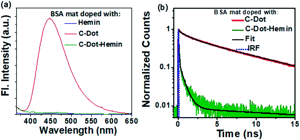 | ||
| Fig. 5 (a) Steady-state photoluminescence spectra of C-Dot (red), C-Dot–hemin HS (green), and hemin (blue) doped BSA mats. (b) Time-resolved luminescence decay trace of C-Dot (red) and C-Dot–hemin HS (green) doped BSA mats at 450 nm after excitation of the samples at 340 nm. | ||
Electronic conduction across the C-Dot–hemin HS doped BSA mat
At the final part of our study, we would like to combine all the different charge transport processes within a single material: The C-Dot–hemin HS doped BSA mat is capable of long-range PT assisted by the C-Dots, long-range ET assisted by hemin, and the discussed photo-induced ET using the HS charge separation process. To follow the long-range charge transport across the protein polymer, we used electrical measurements across a distance of 2.5 mm. We first followed the effect of the molecular dopant (C-Dots vs. hemin vs. C-Dot–hemin HS) on the bulk conductivity of the protein mat using AC EIS measurements (Fig. 6a, displayed in the form of a Nyquist plot). As shown in the figure, the conductivity across the non-doped native BSA mat (∼0.1 mS cm−1) increases upon molecularly doping the mat. In line with previous studies, the conductivity across the hemin-doped BSA mat shows 30 fold increase to a value of ∼3.0 mS cm−1, ascribed to the enhanced electron transport across the hemin molecules, and the conductivity across the C-Dot-doped BSA shows more than 30 fold increase to a value of ∼3.4 mS cm−1, ascribed to the enhanced proton transport assisted by the C-Dot functional groups.9,16 Nevertheless, the most important finding here is that the C-Dot–hemin HS doped BSA mats exhibited the highest measured conductivity, reaching a staggering value of ∼8.5 mS cm−1 (nearly 2 orders of magnitude larger than the conductivity of the non-doped mat), which can be ascribed to the enhanced mixed ionic-electronic conduction across the C-Dot–hemin HS doped BSA mat. At last, we explored how the light-induced charge separation within the C-Dot–hemin HS influences charge conduction across the BSA mat, especially following the observed improved charge separation and transport efficiency within the BSA mat compared to that of the HS in solution. To evaluate the photo responsiveness of our systems (Fig. 6b), we used DC measurements while following the current at a given bias (0.5 V) as a function of time (I–T response) for the hemin-doped and the C-Dot–hemin HS doped BSA mats upon light illumination of the mat at 400 nm (meaning excitation of both the hemin molecule and the C-Dot). The figure clearly shows that the measured photocurrents across the hemin-doped mat are significantly lower than the ones across the C-Dot–hemin HS doped, resulting in more than 3-fold difference between the mats. In these measurements, the hemin molecule acts as a charge separating agent in the C-Dot–hemin HS and BSA plays an important role in the long-range charge separation via hole accepting and transporting properties. An important additional direct indication of the improved charge separation in the C-Dot–hemin doped BSA mat only upon light irradiation can be seen in the cyclic voltammetry (I–V measurements), where new redox peaks are observed only in the presence of light (Fig. 6c), with a much larger magnitude compared to the hemin-doped BSA mat (inset). The other used mats (the non-doped BSA mat and the C-Dot doped mats) do not show the formation of these redox peaks upon light irradiation (Fig. S7†). The enhancement of photocurrent and the appearance of the redox peaks upon light illumination of the C-Dot–hemin HS-BSA mat support our spectroscopic measurements and indicate a long-range charge separation from the photoexcited C-Dot to BSA assisted by the hemin molecules. | ||
| Fig. 6 (a) EIS measurements of the BSA mats with the different dopants. (b) Current vs. time plot at a fixed bias (0.5 V) of the BSA mat doped with hemin (black) and the C-Dot–hemin HS (blue). The inset shows a zoom-in of the first cycle. (c) DC current–voltage (cyclic voltammetry) across the C-Dot–hemin HS doped BSA mat upon light irradiation. The inset shows the same for the hemin-doped mat (the other BSA mats are displayed in Fig. S8†). (d) Schematic representation of the light-induced electron and hole transport across the C-Dot–hemin BSA mat. | ||
A summary of the various charge transfer processes upon light irradiation is presented in Fig. 6d. Extended long-range HT can be represented as a series of sequential short-range HT steps, i.e., a hopping mechanism, of a series of nearest neighbor redox centers. The photoexcited electron of the C-Dot–hemin HS doped BSA mat is transported from the LUMO of hemin to the C-Dot and from the LUMO of the BSA mat to the Fermi level of the gold electrode. Similarly, photogenerated holes are being transported from the C-Dot to the Fermi level of the gold electrode through the HOMO levels of hemin and the BSA mat.
Conclusions
In summary, we explored here the light-induced rapid charge separation within the C-Dot–hemin HS, how the protein biopolymer environment influences this charge separation process, and how it can influence the long-range charge transport across the protein biopolymer. We used steady-state and ultrafast transient spectroscopy to show that upon excitation of the C-Dot, a rapid HT process takes place between the C-Dot and the hemin molecule within the HS configuration. Importantly, we found that the HT rate was more than 3.3 times faster when the HS was doped into the protein biopolymer compared to the rate of the solvated HS, suggesting a fundamental role of the protein biopolymers in the charge separation process. Since it is not possible to determine the exact protein structure within the biopolymer and the exact binding site configuration of the HS, we cannot reveal which amino acids residues are in close contact with the HS, and accordingly, what are the exact energy states allowing the rapid charge separation and HT from the HS. We further used EIS and light-modulated I–T and I–V measurements to explore the contribution of the HS to the long-range charge transport across the protein biopolymer. The EIS measurements showed that the HS-doped biopolymer exhibits a staggering high conductivity under ambient conditions (at room temperature) of 8.5 mS cm−1, which is one of the highest measured conductivity across any biological material. Light-modulated I–T measurements showed a clear improved photocurrent for the HS-doped biopolymer, and the light-modulated I–V measurements showed a clear formation of a redox peak only upon light excitation, all ascribed to the improved HT in the HS-doped biopolymer. All in all, our new protein biopolymer exhibits a myriad of different charge transport properties: (1) PT due to the hydrogen bond network between the amino acid residues, functional groups of the C-Dots, and water molecules. (2) Enhanced ET due to the hemin moieties in it. (3) Light-modulated ET due to the charge separation state of the HS and the observed HT. The biopolymer that we have used here is based on electrospinning the BSA protein, which is one of the most affordable commercially available proteins. Furthermore, the molecular doping approach that we used here is based on the affinity of BSA to a variety of tightly bound ligands; hence no chemistry is needed in this process. Accordingly, our new material is a very promising one for a variety of optoelectronic research and application, from artificial photosynthesis to light-modulated sensors, transistors, and detectors.Experimental section
Materials
Citric acid, ethylenediamine, and 1-(3-(dimethylamino)propyl)-3 ethylcarbodiimide hydrochloride (EDC·HCl) were purchased from Merck and the purity is almost 99.5%. N-Hydroxysulfosuccinimide sodium salt (sulfoNHS) (98%) and hemin (96%) were purchased from Sigma-Aldrich. It is clear from the database of Sigma-Aldrich that hemin contains Fe(III) ions. Other chemicals were purchased from the following companies: BSA from MP Biomedicals which contains fatty acids <0.05 mg g−1, 2,2,2-trifluoroethanol (TFE) from Apollo Scientific (98%), and β-mercaptoethanol from Alfa Aesar (98%).Synthesis of C-Dots
Fluorescent C-Dots were prepared from citric acid by microwave treatment following a reported synthesis method.34 Hydrophilic C-Dots were synthesized by dissolving 1 g of citric acid (Merck) and 0.384 mL of ethylenediamine (EDA, Merck) in 10 mL of distilled water. To get a clear solution, the mixed solution was sonicated for 10 min, followed by heating it using a microwave oven at 300 W, 150 °C, for 10 min. Upon cooling the mixture, a brown-colored solution was formed, followed by the precipitation of the C-Dots using a methanol and acetone mixture (1![[thin space (1/6-em)]](https://www.rsc.org/images/entities/char_2009.gif) :1), and separating them using a centrifuge at 10000 rpm for 10 min. The latter purification process was repeated several times. For further characterization, the pure product was dissolved in distilled water.
:1), and separating them using a centrifuge at 10000 rpm for 10 min. The latter purification process was repeated several times. For further characterization, the pure product was dissolved in distilled water.
Synthesis of the C-Dot–hemin heterostructure (C-Dot–hemin HS)
Hemin (0.05 mmol) was dissolved in 4 mL DMF and 0.1 mmol of 1-(3-dimethylaminopropyl)-3-ethylcarbodiimide hydrochloride (EDC) (Merck), and 0.1 mmol of N-hydroxysulfosuccinimide (NHS) (Sigma) were added to this solution in a nitrogen atmosphere, followed by stirring for 30 min at room temperature to activate the carboxylic group of the hemin. 25 mg of the C-Dot was added to the solution and stirred overnight to complete the reaction, and the synthesis pathway is shown in Scheme 1. Following the formation of the C-Dot–hemin, the solvent was removed from the product and 0.1 M HCl was added, while unreacted hemin was removed from the mixture by a solvent extraction method using CH3Cl.Preparation of the C-Dot–hemin HS doped BSA mat
For making the BSA mat, BSA (MP Biomedicals) was dissolved in 90% 2,2,2-trifluoroethanol (TFE) (Apollo Scientific) with a final concentration of BSA solution of 14% (w/v). 5% (v/v) of β-mercaptoethanol (Alfa Aesar) was mixed into the solution. This solution was loaded onto a custom-built electrospinning system, and the BSA mat was formed upon applying a bias of 12 kV on a 24-gauge blunt needle while grounding the collector; a constant distance of 12 cm between the collector and the end of the needle and an injection rate of 1.3 mL min−1 were maintained for the entire spinning process. The doped BSA mats were made by keeping a piece of free-standing BSA mat in the dopant solutions overnight, and after complete adsorption of dopant, the doped BSA mats were washed with water several times to remove the excess unbounded dopant. All the experiments were carried out using a BSA mat of around 0.06 mm and 1 cm × 1 cm thickness and dimension, respectively.Microscopy
Transmission electron microscope (JEOL, JEM-2100F microscope) was used for morphology characterization of the C-Dot and C-Dot–hemin HS using a ZrO/W(100) Schottky electron source with accelerating voltages of 200 keV or 120 keV. The C-Dot and C-Dot–hemin HS samples were prepared by placing a drop of a diluted solution on a carbon-coated copper grid and were dried in air overnight. Electron-dispersive spectroscopy (EDS) was carried out using the same instrument in the following configuration: a JEM-2100F field emission gun electron microscope equipped with an EDS, diffraction pattern software, and high angle annular dark-field scanning TEM detector.Spectroscopy
The absorption spectra and photoluminescence were measured using a Cary 60 (Agilent) UV-Vis and FS5 (Edinburgh instruments) spectrophotometer, respectively. The time-correlated single-photon counting (TCSPC) technique was used to measure the fluorescence lifetimes using a CHIMERA spectrometer (Light Conversion) with an excitation wavelength of 340 nm. The laser system was based on a 10 Nb–Yb-based laser amplifier (PHAROS, Light-Conversion) with pulses of <190 fs, operating at 1 MHz (pulse intensity of 10 μJ). The output laser beam (at 1035 nm) was seeded by an optical parametric amplifier (ORPHEUS, Light-Conversion) followed by second and fourth harmonic generation to produce the desired excitation wavelength of 340 nm. The steady-state and time-resolved measurements of dry BSA mats were carried out in the reflection mode by placing the mat between two quartz plates. The fluorescence lifetime was calculated using the Carpetview fitting software. A HELIOS transient absorption spectrometer (Ultrafast Systems) was used to study the femtosecond pump-probe transient absorption. The laser system was based on a regenerative amplifier (Spitfire Ace Ti:Sapphire Amplifier, Spectra-Physics), operated at 800 nm at a repetition rate of 1 kHz and pulse duration of ∼80 fs, seeded by a Ti:sapphire oscillator. The output of the amplifier was split into pump and probe beam lines, where the pump beam was produced by passing a part of the regenerative amplifier through an optical parametric amplifier (TOPAS, Light Conversion), altered to the required wavelength and then fed into the spectrometer through a synchronized chopper, thus generating 500 Hz synced signals. The probe beam path followed a computer managed delay stage onto a CaF2 crystal to achieve white light continuum. The data analysis was carried out using Surface Xplorer software. Transient absorption was performed using a Quartz cell with a 2 mm sample path length. The FTIR spectra were recorded using Bruker ALPHA FTIR spectrometer with an attenuated total reflectance (ATR) mode and the background was recorded in air and subtracted from the spectra.Electrical measurements
Impedance was recorded using an MTZ-35 impedance/gain-phase analyzer (Bio-logic) in the frequency range of 10 MHz to 10 Hz with an applied AC bias of 50 mV (no DC bias was applied). The I–V measurements were acquired using a source-measuring unit (B2901A, Keysight). Gold finger electrode substrates (distance of 2.5 mm between gold fingers) and micromanipulator probes (contact with the gold electrodes) were used to measure the impedance and I–V study. Non-doped, C-Dot, and C-Dot–hemin HS doped BSA mats were placed on the electrode configuration and excess water was removed gently with filter paper before the electrical measurements. For the light-modulated experiments, an LED pen was used with a power of 35 mW, centered around.Author contributions
S. M. constructed the research work, synthesized the materials and other characterizations and wrote the manuscript. N. A. and H. N. G. revised the manuscript. N. G. carried out TA measurements and S. B. has taken the TEM images and FTIR for the manuscript. All authors actively took part in the discussion of results and commented on the manuscript.Conflicts of interest
The authors declare no conflict of interestAcknowledgements
S. M. thanks the PBC fellowship of Israel's Council of Higher Education for financial support. N. G. and S. B. acknowledge the Council of Scientific and Industrial Research, Institute of Nano Science and Technology, Mohali, and Indian Institute of Science Education and Research-Kolkata, India for research fellowship. N. A. thanks the Binational Science Foundation (grant number 2018239) and the Ministry of Science and Technology (grant numbers 3-16243 and 3-16312) for financial support. We thank the Russel Berrie Nanotechnology Institute (RBNI), Grand Technion Energy Program (GTEP) and the Institute of Nano science and Technology (INST) for their support in equipment use.References
- N. Amdursky, D. Marchak, L. Sepunaru, I. Pecht, M. Sheves and D. Cahen, Adv. Mater., 2014, 26, 7142–7161 CrossRef CAS PubMed.
- N. Amdursky, E. D. Głowacki and P. Meredith, Adv. Mater., 2019, 31, 1–28 CrossRef PubMed.
- A. Remy and K. Gerwert, Nat. Struct. Biol., 2003, 10, 637–644 CrossRef CAS PubMed.
- H. Luecke, H. T. Richter and J. K. Lanyi, Science, 1998, 280, 1934–1937 CrossRef CAS PubMed.
- J. E. Frew and H. A. Hill, Philos. Trans. R. Soc., B, 1987, 316, 95–106 CAS.
- J. Liu, V. M. Friebe, R. N. Frese and M. R. Jones, Nat. Commun., 2020, 11, 1542 CrossRef CAS PubMed.
- A. Nitzan and M. A. Ratner, Science, 2003, 300, 1384–1389 CrossRef CAS PubMed.
- A. B. Mostert, B. J. Powell, F. L. Pratt, G. R. Hanson, T. Sarna, I. R. Gentle and P. Meredith, Proc. Natl. Acad. Sci. U. S. A., 2012, 109, 8943–8947 CrossRef CAS PubMed.
- N. Amdursky, X. Wang, P. Meredith, D. J. Riley, D. J. Payne, D. D. C. Bradley and M. M. Stevens, Adv. Mater., 2017, 29, 1700810 CrossRef PubMed.
- S. Mondal, Y. Agam, R. Nandi and N. Amdursky, Chem. Sci., 2020, 11, 3547–3556 RSC.
- C. Zhong, Y. Deng, A. F. Roudsari, A. Kapetanovic, M. P. Anantram and M. Rolandi, Nat. Commun., 2011, 2, 2–6 RSC.
- N. Amdursky, X. Wang, P. Meredith, D. D. C. Bradley and M. M. Stevens, Adv. Mater., 2016, 28, 2692–2698 CrossRef CAS PubMed.
- Y. Dror, T. Ziv, V. Makarov, H. Wolf, A. Admon and E. Zussman, Biomacromolecules, 2008, 9, 2749–2754 CrossRef CAS PubMed.
- N. Amdursky, M. M. Mazo, M. R. Thomas, E. J. Humphrey, J. L. Puetzer, J. P. St-Pierre, S. C. Skaalure, R. M. Richardson, C. M. Terracciano and M. M. Stevens, J. Mater. Chem. B, 2018, 6, 5604–5612 RSC.
- J. A. Hamilton, S. Era, S. P. Bhamidipati and R. G. Reed, Proc. Natl. Acad. Sci. U. S. A., 1991, 88, 2051–2054 CrossRef CAS PubMed.
- E. Mentovich, B. Belgorodsky, M. Gozin, S. Richter and H. Cohen, J. Am. Chem. Soc., 2012, 134, 8468–8473 CrossRef CAS PubMed.
- Y. Agam, R. Nandi, A. Kaushansky, U. Peskin and N. Amdursky, Proc. Natl. Acad. Sci. U. S. A., 2020, 117, 32260–32266 CrossRef CAS PubMed.
- S. Mondal, Y. Agam and N. Amdursky, Small, 2020, 16, 2005526 CrossRef CAS PubMed.
- S. Deka, A. Falqui, G. Bertoni, C. Sangregorio, G. Poneti, G. Morello, M. De Giorgi, C. Giannini, R. Cingolani, L. Manna and P. D. Cozzoli, J. Am. Chem. Soc., 2009, 131, 12817–12828 CrossRef CAS PubMed.
- S. Mondal, A. Yucknovsky, K. Akulov, N. Ghorai, T. Schwartz, H. N. Ghosh and N. Amdursky, J. Am. Chem. Soc., 2019, 141, 15413–15422 CrossRef CAS PubMed.
- Z. Tian, X. Zhang, D. Li, D. Zhou, P. Jing, D. Shen, S. Qu, R. Zboril and A. L. Rogach, Adv. Opt. Mater., 2017, 19, 1700416 CrossRef.
- V. Strauss, J. T. Margraf, C. Dolle, B. Butz, T. J. Nacken, J. Walter, W. Bauer, W. Peukert, E. Spiecker, T. Clark and D. M. Guldi, J. Am. Chem. Soc., 2014, 136, 17308–17316 CrossRef CAS PubMed.
- Y. Sun, B. Zhou, Y. Lin, W. Wang, K. A. S. Fernando, P. Pathak, M. J. Meziani, B. A. Harruff, X. Wang, H. Wang, P. G. Luo, H. Yang, M. E. Kose, B. Chen, L. M. Veca, S. Xie and S. Carolina, J. Am. Chem. Soc., 2006, 7756–7757 CrossRef CAS PubMed.
- L. Wang, H. Y. Wang, Y. Wang, S. J. Zhu, Y. L. Zhang, J. H. Zhang, Q. D. Chen, W. Han, H. L. Xu, B. Yang and H. B. Sun, Adv. Mater., 2013, 25, 6539–6545 CrossRef CAS PubMed.
- S. Mondal and P. Purkayastha, J. Phys. Chem. C, 2016, 120, 14365–14371 CrossRef CAS.
- S. Mondal, M. Chatti, A. Mallick and P. Purkayastha, Chem. Commun., 2014, 50, 6890–6893 RSC.
- S. Mondal, T. Das, A. Maity, S. K. Seth and P. Purkayastha, J. Phys. Chem. C, 2015, 119, 13887–13892 CrossRef CAS.
- A. N. Martin, A. Ferrer-ruiz, T. Scharl, L. Rodríguez-pérez, A. Cadranel, Á. Herranz and D. M. Guldi, Angew. Chem., Int. Ed., 2017, 56, 12097–12101 CrossRef PubMed.
- A. Cadranel, D. M. Guldi, F. Arcudi and V. Strauss, Angew. Chem., Int. Ed., 2018, 57, 1001–1005 CrossRef PubMed.
- S. Verma and H. N. Ghosh, J. Phys. Chem. Lett., 2012, 3, 1877–1884 CrossRef CAS PubMed.
- T. Itoh, T. Yamada, Y. Kodera, A. Matsushima, M. Hiroto, K. Sakurai, H. Nishimura and Y. Inada, Bioconjugate Chem., 2001, 12, 3–6 CrossRef CAS PubMed.
- S. Lu, L. Sui, J. Liu, S. Zhu, A. Chen, M. Jin and B. Yang, Adv. Mater., 2017, 29, 1–6 Search PubMed.
- L. Wang, S. Zhu, H. Wang, Y. Wang, Y. Hao and J. Zhang, Adv. Opt. Mater., 2013, 1, 264–271 CrossRef.
- C. Yu, X. Li, F. Zeng, F. Zheng and S. Wu, Chem. Commun., 2013, 49, 403–405 RSC.
Footnote |
| † Electronic supplementary information (ESI) available. See DOI: 10.1039/d1sc00487e |
| This journal is © The Royal Society of Chemistry 2021 |