 Open Access Article
A rationally designed two-dimensional MoSe2/Ti2CO2 heterojunction for photocatalytic overall water splitting: simultaneously suppressing electron–hole recombination and photocorrosion†
Cen-Feng
Fu
,
Xingxing
Li
 and
Jinlong
Yang
 *
*
Hefei National Laboratory of Physical Science at the Microscale, Department of Chemical Physics, Synergetic Innovation Center of Quantum Information & Quantum Physics, University of Science and Technology of China, Anhui 230026, China. E-mail: jlyang@ustc.edu.cn
First published on 13th January 2021
Abstract
Electron–hole recombination and photocorrosion are two challenges that seriously limit the application of two-dimensional (2D) transition metal dichalcogenides (TMDs) for photocatalytic water splitting. In this work, we propose a 2D van der Waals MoSe2/Ti2CO2 heterojunction that features promising resistance to both electron–hole recombination and photocorrosion existing in TMDs. By means of first-principles calculations, the MoSe2/Ti2CO2 heterojunction is demonstrated to be a direct Z-scheme photocatalyst for overall water splitting with MoSe2 and Ti2CO2 serving as photocatalysts for hydrogen and oxygen evolution reactions, respectively, which is beneficial to electron–hole separation. The ultrafast migration of photo-generated holes from MoSe2 to Ti2CO2 as well as the anti-photocorrosion ability of Ti2CO2 are responsible for photocatalytic stability. This heterojunction is experimentally reachable and exhibits a high solar-to-hydrogen efficiency of 12%. The strategy proposed here paves the way for developing 2D photocatalysts for water splitting with high performance and stability in experiments.
Introduction
Two-dimensional (2D) photocatalysts for water splitting have attracted significant attention due to their unique electronic and optical properties compared to traditional bulk materials.1–6 The representative 2D MoS2 nanosheets of transition metal dichalcogenides (TMDs) have been demonstrated to be potential photocatalysts for overall water splitting.7–10 The homogeneous distributions of photo-generated electrons and holes on the layers of 2D TMDs make both the hydrogen evolution reaction (HER) and oxygen evolution reaction (OER) proceed on the same surface. This results in electron–hole recombination, which reduces the energy conversion efficiency.3 On the other hand, chalcogenide-based photocatalysts for water splitting suffer from the photocorrosion problem,10,11 thus seriously restricting their practical usage. When photocorrosion occurs, the photo-generated electrons or holes will not participate in water decomposition, while resulting in the semiconductors themselves being reduced or oxidized, and leading to material disintegration.12,13 For chalcogenide-based photocatalysts, photocorrosion results from the oxidation of the chalcogen components by the photo-generated holes.11–13 For instance, the previous reports suggested that the severe photocorrosion issue occurs in the edges as well as defect positions of MoS2 nanosheets.14 Consequently, the electron–hole recombination and photocorrosion issues seriously limit the application of TMDs for photocatalytic water splitting.For bulk photocatalysts, some rationally designed heterojunctions show effective inhibition of both electron–hole recombination15–17 and photocorrosion18–20 in experiments. As regards 2D TMDs for photocatalytic water splitting, constructing 2D type-II21–24 and Z-scheme25–28 heterojunctions has been reported to be effective in enhancing electron–hole separation. For these 2D heterojunctions, the OER proceeds relying on the chalcogen-containing materials and thus the photocorrosion situation is inevitable. To date, the challenge of addressing the photocorrosion problem in 2D chalcogenide-based photocatalysts has remained unsolved. It is urgent to find an avenue to simultaneously resist electron–hole recombination as well as photocorrosion issues for TMDs.
In this work, we propose that both the electron–hole recombination and photocorrosion phenomena in 2D TMDs are successfully suppressed via the rational design of 2D heterojunctions using a specific kind of semiconductor. This kind of semiconductor should hold these features: (1) the conduction band (CB) being slightly higher than the valence band (VB) of TMDs to achieve the ultrafast collection of the photo-generated holes from TMDs; (2) the band alignment being suitable for the OER, while TMDs serving as photocatalysts for the HER; (3) featuring the anti-photocorrosion ability to the photo-generated holes. Here, the direct Z-scheme heterojunction is chosen due to its significant advantages compared to type-II and traditional Z-scheme heterojunctions with mediators.29 By means of first-principles calculations, the 2D vdW heterojunction of MoSe2/Ti2CO2 is demonstrated to be a good candidate. Ti2CO2 belongs to 2D materials of transition metal carbides (MXenes), which have been widely explored for energy storage and photoelectrocatalysis in experiments.30–33 The 2D vdW heterojunctions can be easily prepared through mixing the dispersions of the two components according to the experimental reports.34–36 The band structures reveal that this heterojunction is a direct Z-scheme photocatalyst for overall water splitting with MoSe2 and Ti2CO2 acting as the HER and OER photocatalysts, respectively, which is beneficial for electron–hole separation. Non-adiabatic molecular dynamics (NAMD) simulations indicate that more than 65% of the photo-generated holes migrate from MoSe2 to Ti2CO2 within 0.5 ps, which significantly reduces the probability of photocorrosion occurring in MoSe2. Further studies on the free energy along the catalytic reaction routes show that the OER can occur spontaneously on the surface of Ti2CO2. Meanwhile, the Ti2CO2 material itself can suppress photocorrosion and its surface oxygen will not be oxidized by photo-generated holes. Moreover, it is worth mentioning that the theoretically predicted solar-to-hydrogen (STH) efficiency of this heterojunction is up to 12%, exceeding the requirement for 10% STH efficiency for practical applications.37
Results and discussion
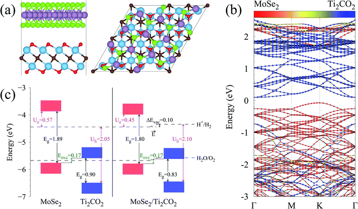
The calculated lattice parameters of the MoSe2 and Ti2CO2 monolayers are 3.32 and 3.03 Å, respectively, which are in agreement with the previously reported results.25–27,38,39 A super cell for MoSe2 and a 4 × 4 super cell for Ti2CO2 are employed to construct the 2D vdW heterojunction with a lattice constant of 12.04 Å, which ensures that the lattice mismatches for both MoSe2 and Ti2CO2 are within 1%. The configurations of the MoSe2/Ti2CO2 heterojunction with different stacking patterns are examined (Fig. S1†). It is found that the effect of different stacking patterns on the binding energy and vertical distance between the two components of the heterojunction is negligible (Table S1†). The configuration (shown in Fig. 1(a)) with the largest binding energy is used for the following calculations. For this configuration, the vertical distance between MoSe2 and Ti2CO2 is 3.07 Å and their binding energy is confirmed to be −16.8 meV per atom (−15.9 meV Å−2), suggesting the presence of weak vdW interactions in the MoSe2/Ti2CO2 heterojunction. This binding energy is comparable to that (−30 meV Å−2) of a 2D black phosphorus/BiVO4 heterojunction,40 which has been fabricated as a direct Z-scheme photocatalyst for water splitting in the experiment through a solution mixing method.34 Solution mixing is simple and low-cost to experimentally fabricate 2D vdW heterojunctions, including 2D direct Z-scheme photocatalysts of aza-CMP/C2N35 and α-Fe2O3/g-C3N4.36 Except for the solution mixing method, there are other protocols for fabricating 2D vdW heterojunctions in experiments, including mechanical transfer and direct growth.41,42 The stability of this heterojunction in water environments is examined by ab initio molecular dynamics (AIMD) simulations. The results reveal that the whole system reaches equilibrium after 4 ps and there is no structural disorder for the heterojunction nor reactions of the surface H2O molecules on the heterojunction during the whole 10 ps simulation (Fig. S2†). Thus, it is confirmed that the MoSe2/Ti2CO2 heterojunction is sufficiently stable in water.
The band structure of the MoSe2/Ti2CO2 heterojunction calculated by the HSE06 hybrid functional is presented in Fig. 1(b). The band gap is 0.17 eV. The valence band maximum (VBM) appears at the K position mainly contributed by MoSe2 and the conduction band minimum (CBM) arises at the Γ position mainly contributed by Ti2CO2. More detailed density of states (DOS) information can be seen in Fig. S4† and the spatial distribution of the VB and CB for the heterojunction is shown in Fig. S5.†
Fig. 1(c) illustrates the band edge alignments of the MoSe2 and Ti2CO2 monolayers as well as their complex. The MoSe2 monolayer features the CBM above the H2/H2O potential while the Ti2CO2 monolayer shows the VBM below the H2O/O2 potential. This indicates that the MoSe2 and Ti2CO2 monolayers can serve as the HER and OER photocatalysts, respectively. The MoSe2/Ti2CO2 heterojunction holds the same band edge alignment. Moreover, the CBM of Ti2CO2 is slightly higher than the VBM of MoSe2 with an offset (Eovc) of 0.17 eV, which benefits the photo-generated carriers rapidly migrating between the VB of MoSe2 and the CB of Ti2CO2. Such a band edge alignment means that the MoSe2/Ti2CO2 heterojunction is a direct Z-scheme photocatalyst for overall water splitting, which is favorable for electron–hole separation. The comparisons regarding the band edge alignments of the free-standing monolayers and the heterojunction in Fig. 1(c) reveal the variations for the band gaps of MoSe2 and Ti2CO2 as well as Ue and Uh, which is ascribed to the interactions between the MoSe2 and Ti2CO2 monolayers. Attributed to the larger work function of Ti2CO2 (5.66 eV) compared with MoSe2 (4.48 eV), the charge redistribution phenomenon occurs (Fig. S6†) when these two kinds of monolayers contact each other. Bader charge analysis reveals that about 0.40 electron transfer from MoSe2 to Ti2CO2 for the whole system. The corresponding electron transfer for MoSe2 is only 0.03 per formula, indicating that the charge transfer is weak. Therefore, the effect of charge transfer on the band structure is small and the dominant interaction between MoSe2 and Ti2CO2 derives from the van der Waals interaction. Additionally, the charge redistribution brings about an electric field along the perpendicular direction pointing from MoSe2 to Ti2CO2, thus leading to these two materials exhibiting different vacuum levels (representing by the ΔEvac in Fig. 1(c)). The appearance of the vertical electric field is helpful with facilitating the recombination of the photo-generated holes in the  VB and the photo-generated electrons in the
  CB. Simultaneously, both the undesired migrations of the photo-generated electrons from the
  CB to the
  CB and the photo-generated holes from the
  VB to the
  VB are well hindered. These are beneficial for the MoSe2/Ti2CO2 heterojunction to facilitate photocatalytic water splitting by the Z-scheme mechanism.
The strain effects on the electronic structures of the MoSe2/Ti2CO2 heterojunction have also been investigated (Fig. S7†). As strain varies from −2% to 2%, the band gap of MoSe2 gradually decreases, while that of Ti2CO2 gradually increases. Within the whole strain change range, the MoSe2/Ti2CO2 heterojunction keeps the suitable band edge alignment for Z-scheme photocatalytic water splitting. Additionally, the Ue and Uh values show an increasing trend with increasing strain, hinting that the compression strain is much more preferred for the MoSe2/Ti2CO2 system to catalyze water decomposition.
The ultrafast migrations of the photo-generated carriers between the  VB and the
  CB are further demonstrated by NAMD simulations.43–45 According to the above discussion, the
  VB and the
  CB are chosen as the initial states for photo-generated holes and electrons, respectively, to explore interlayer and intralayer electron–hole recombination. As shown in Fig. 2(b), within 0.5 ps, more than 85% of the photo-generated holes recombine with electrons. Among them over 65% recombine with electrons in Ti2CO2 and only 20% belong to intralayer electron–hole recombination. Around 95% of the photo-generated electrons recombine with holes within 0.5 ps (Fig. 2(c)). The population for the interlayer and intralayer electron–hole recombination is 60% and 35%, respectively. The NAMD simulations reveal that more than 65% of photo-generated holes transfer from MoSe2 to Ti2CO2 within 0.5 ps, which greatly reduces the possibility of the Se components being oxidized by the photo-generated holes in MoSe2, thereby being favorable of the elimination of photocorrosion.
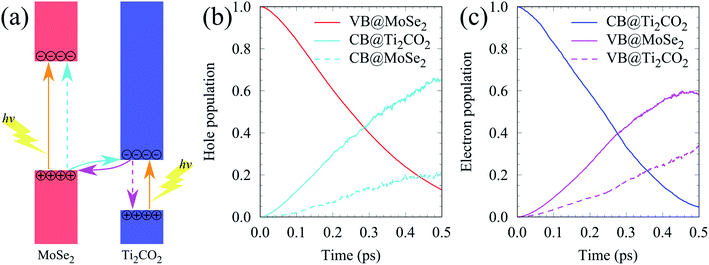 | ||
| Fig. 2 (a) Schematic diagram of the photogenerated carrier transfer pathway for the MoSe2/Ti2CO2 heterojunction. (b and c) The time dependent hole and electron population. | ||
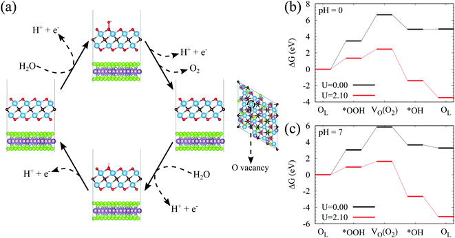
The above studies have clearly implied that the MoSe2/Ti2CO2 heterojunction has Z-scheme band edge alignment with ultrafast interlayer electron–hole recombination, which restricts photocorrosion arising in the MoSe2 monolayer. The further examination of the photocatalytic activity and stability of Ti2CO2 is performed by investigating the free energy variations during the OER process. The OER is considered as a four-electron reaction process, where there are several intermediate states of *OH, *O, and *OOH absorbed on the material surface. In the first step, the H2O molecule loses an electron–proton pair to form *OH. In the second step, *OH is oxidized to *O. In the third step, *O reacts with another H2O molecule to yield *OOH. In the last step, *OOH releases an electron–proton pair and then desorbs from the material surface to achieve the production of the O2 molecule. The various intermediate state configurations involved in the OER are presented in Fig. 3(a). The most stable absorbed H2O molecule locates at the top of the Ti atom (Fig. S10†). For the structure of the absorbed *OH, the Ti atom moves up from the subsurface and bonds to the O atom of *OH after structural optimization. This Ti atom is the active site during the OER process. It stays on the surface and bonds to the adsorbed *O and *OOH. After the formation of the O2 molecule (Fig. S11†), this Ti atom goes back to the subsurface and the surface of Ti2CO2 recovers. Fig. 3(b and c) reveal the free energy curves of the OER happening on the  surface. It is found that among the four procedures, the reaction for *O transforming into *OOH is the rate-determining step with free energy variation (ΔG) equal to 1.39 eV at pH = 7. By taking the extra potential provided by photo-generated holes into account, the ΔG of all four element reactions decrease (Fig. 3(b)), meaning that the whole OER can occur spontaneously from the viewpoint of energy. Albeit the pH value descends to 0 corresponding to strongly acid environments, the spontaneous OER process is still realized under light irradiation conditions (Fig. 3(c)). Additionally, we inspected the strain effects on ΔG during the OER process (Fig. S12†). The results reveal that the OER can proceed spontaneously via light illumination within a strain range of −2% to 2%.
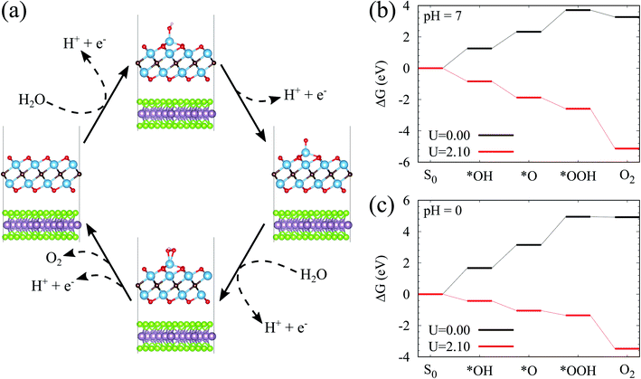 | ||
| Fig. 3 (a) Proposed photocatalytic pathways for the OER on the surface of Ti2CO2. (b and c) Free energy diagrams for the OER on the surface of Ti2CO2 at pH = 7 and pH = 0, respectively. | ||
To clarify the photocatalytic stability of Ti2CO2, we explore the reaction mechanism for Ti2CO2 oxidized by the photo-generated holes. For the Ti2CO2 monolayer, the Ti and C atoms are protected by the surface lattice O (OL), so OL will be oxidized by the photo-generated holes firstly. In the following content, ΔG for the OER process involving OL of Ti2CO2 is investigated. Firstly, the reaction happens between OL and the H2O molecule to generate *OOH; Secondly, *OOH loses an electron–proton pair to form O2, simultaneously leaving an O vacancy (VO) on the material surface; Thirdly, the H2O molecule releases an electron–proton pair at the VO site to yield *OH; Finally, *OH releases an electron–proton pair to produce OL (the intermediate state configurations corresponding to the reaction steps can be seen in Fig. 4(a)). As presented in Fig. 4(b), at pH = 0, both the first and second steps exhibit rather large ΔG, attaining 3.45 and 3.21 eV, respectively, while the ΔG of the last two steps are comparatively small, being −1.77 and 0.03 eV, respectively. Although the additional energy provided by photo-generated holes is considered, ΔG of the first two steps is still higher than 1.10 eV, uncovering the fact that it is difficult for OL joining in the OER to generate O2. However, the ΔG of the last two steps tend to be negative, indicating that the surface VO of Ti2CO2 easily reacts with H2O molecules to recover the perfect surface morphology. According to the OER free energy changes, it can be reasonably concluded that Ti2CO2 features promising corrosion resistance to the photo-generated holes. When the pH value increases to 7, Ti2CO2 still shows good anti-photocorrosion (Fig. 4(c)).
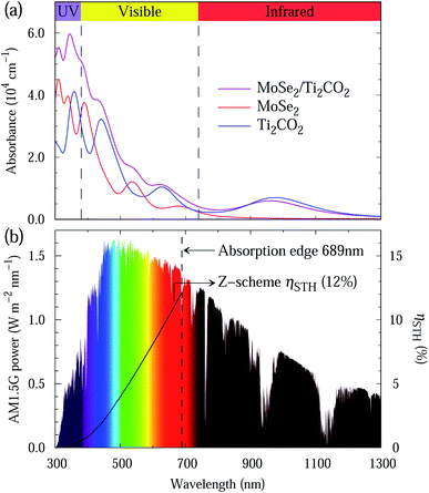
Light absorption is a crucial indicator to assess photocatalysts. The light absorption spectra of the MoSe2 and Ti2CO2 monolayers as well as the MoSe2/Ti2CO2 heterojunction are presented in Fig. 5(a). The preferable light absorption region for the MoSe2 monolayer locates in the scope of visible and ultraviolet light. Benefiting from the smaller band gap of the Ti2CO2 monolayer, its light absorption can extend into the near-infrared light region. Accordingly, the MoSe2/Ti2CO2 heterojunction demonstrates promising light absorption in the near-infrared, visible and ultraviolet light areas, indicative of the high STH efficiency. Referring to the previous work,27,46 we calculated the STH efficiency of the MoSe2/Ti2CO2 complex. The up limit of the theoretically predicted STH efficiency is as high as 12% (Fig. 5(b)), which is higher than the theoretical predictions of 10.5% and 9.3% for the Z-scheme photocatalysts of MoSe2/SnSe2 and WSe2/SnSe2,27 respectively, and comparable to the experimentally reported efficiency of 13% gained in dye-sensitized solar cells.47 Moreover, the predicted STH efficiency exceeds the required criterion of 10% for commercial applications,37 which makes it a promising photocatalyst candidate for hydrogen production.
Conclusions
In summary, by employing first-principles calculations, we firstly construct a 2D vdW MoSe2/Ti2CO2 heterojunction that has resistance to both electron–hole recombination and photocorrosion existing in the 2D TMD family for photocatalytic water splitting. The 2D MoSe2/Ti2CO2 heterojunction is demonstrated to be a direct Z-scheme photocatalyst for overall water splitting. The HER and OER proceed on the surfaces of MoSe2 and Ti2CO2, respectively, which is favourable for electron–hole separation. NAMD simulations reveal that over 65% of the photo-generated holes migrate from MoSe2 to Ti2CO2 within 0.5 ps, which effectively brings down the possibility of photocorrosion in MoSe2 caused by the photo-generated holes. The free energy variations along the OER pathway confirm that the OER occurs spontaneously on the surface under light irradiation. Meanwhile, the exorbitant free energy rises suppress the
  surface lattice O oxidized by the photo-generated holes, bringing about promising anti-photocorrosion. The MoSe2/Ti2CO2 heterojunction shows good light absorption in the regions of the near-infrared, visible and ultraviolet light, thus resulting in a high STH efficiency of 12%. Such efficiency outperforms the 10% critical value, indicating the substantial potential of the MoSe2/Ti2CO2 heterojunction for commercial applications. The concept proposed in this work can be further extended to other 2D laminates, to further alleviate the occurrence of photocorrosion for sulfide-, nitride-, and phosphide-based photocatalysts.
Conflicts of interest
The authors declare no conflict of interest.Acknowledgements
This work was partially supported by the National Natural Science Foundation of China (Grant No. 21688102 and 22073085), National Key Research & Development Program of China (Grant No. 2016YFA0200604), Anhui Natural Science Foundation (Grant No. 2008085QB71), and Anhui Initiative in Quantum Information Technologies (Grant No. AHY090400). The numerical calculations have been carried out on the supercomputing system in the USTC-SCC and CAS-SCC.References
- G. Liu, C. Zhen, Y. Kang, L. Wang and H.-M. Cheng, Chem. Soc. Rev., 2018, 47, 6410–6444 RSC.
- T. Su, Q. Shao, Z. Qin, Z. Guo and Z. Wu, ACS Catal., 2018, 8, 2253–2276 CrossRef CAS.
- M. Faraji, M. Yousefi, S. Yousefzadeh, M. Zirak, N. Naseri, T. H. Jeon, W. Choi and A. Z. Moshfegh, Energy Environ. Sci., 2019, 12, 59–95 RSC.
- Y. Zhao, S. Zhang, R. Shi, G. I. N. Waterhouse, J. Tang and T. Zhang, Mater. Today, 2020, 34, 78–91 CrossRef CAS.
- C.-F. Fu, X. Wu and J. Yang, Adv. Mater., 2018, 30, 1802106 CrossRef.
- C.-F. Fu, C. Zhao, Q. Zheng, X. Li, J. Zhao and J. Yang, Sci. China Chem., 2020, 63, 1134–1141 CrossRef CAS.
- R. Lv, J. A. Robinson, R. E. Schaak, D. Sun, Y. Sun, T. E. Mallouk and M. Terrones, Acc. Chem. Res., 2015, 48, 56–64 CrossRef CAS.
- H. Li, C. Tsai, A. L. Koh, L. Cai, A. W. Contryman, A. H. Fragapane, J. Zhao, H. S. Han, H. C. Manoharan, F. Abild-Pedersen, J. K. Nørskov and X. Zheng, Nat. Mater., 2016, 15, 48–53 CrossRef CAS.
- Z. Li, X. Meng and Z. Zhang, J. Photochem. Photobiol. C Photochem. Rev., 2018, 35, 39–55 CrossRef CAS.
- S. Chandrasekaran, L. Yao, L. Deng, C. Bowen, Y. Zhang, S. Chen, Z. Lin, F. Peng and P. Zhang, Chem. Soc. Rev., 2019, 48, 4178–4280 RSC.
- A. B. Ellis, S. W. Kaiser, J. M. Bolts and M. S. Wrighton, J. Am. Chem. Soc., 1977, 99, 2839–2848 CrossRef CAS.
- J. Su, Y. Wei and L. Vayssieres, J. Phys. Chem. Lett., 2017, 8, 5228–5238 CrossRef CAS.
- B. Weng, M.-Y. Qi, C. Han, Z.-R. Tang and Y.-J. Xu, ACS Catal., 2019, 9, 4642–4687 CrossRef CAS.
- E. Parzinger, B. Miller, B. Blaschke, J. A. Garrido, J. W. Ager, A. Holleitner and U. Wurstbauer, ACS Nano, 2015, 9, 11302–11309 CrossRef CAS.
- H. Wang, L. Zhang, Z. Chen, J. Hu, S. Li, Z. Wang, J. Liu and X. Wang, Chem. Soc. Rev., 2014, 43, 5234–5244 RSC.
- J. Low, J. Yu, M. Jaroniec, S. Wageh and A. A. Al-Ghamdi, Adv. Mater., 2017, 29, 1601694 CrossRef.
- Y. Wang, H. Suzuki, J. Xie, O. Tomita, D. J. Martin, M. Higashi, D. Kong, R. Abe and J. Tang, Chem. Rev., 2018, 118, 5201–5241 CrossRef CAS.
- K. Iwashina, A. Iwase, Y. H. Ng, R. Amal and A. Kudo, J. Am. Chem. Soc., 2015, 137, 604–607 CrossRef CAS.
- S. Wang, B. Y. Guan, Y. Lu and X. W. Lou, J. Am. Chem. Soc., 2017, 139, 17305–17308 CrossRef CAS.
- J. Zhang, Y. Guo, Y. Xiong, D. Zhou and S. Dong, J. Catal., 2017, 356, 1–13 CrossRef CAS.
- R. Kumar, D. Das and A. K. Singh, J. Catal., 2018, 359, 143–150 CrossRef CAS.
- C. He, J. H. Zhang, W. X. Zhang and T. T. Li, J. Phys. Chem. Lett., 2019, 10, 3122–3128 CrossRef CAS.
- B. Gao, J.-R. Zhang, L. Chen, J. Guo, S. Shen, C.-T. Au, S.-F. Yin and M.-Q. Cai, Appl. Surf. Sci., 2019, 492, 157–165 CrossRef CAS.
- Y. Yao, J. Cao, W. Yin, L. Yang and X. Wei, J. Phys. D. Appl. Phys., 2019, 53, 55108 CrossRef.
- C.-F. Fu, Q. Luo, X. Li and J. Yang, J. Mater. Chem. A, 2016, 4, 18892–18898 RSC.
- C.-F. Fu, R. Zhang, Q. Luo, X. Li and J. Yang, J. Comput. Chem., 2019, 40, 980–987 CrossRef CAS.
- Y. Fan, J. Wang and M. Zhao, Nanoscale, 2019, 11, 14836–14843 RSC.
- Z. Zhou, X. Niu, Y. Zhang and J. Wang, J. Mater. Chem. A, 2019, 7, 21835–21842 RSC.
- J. Low, C. Jiang, B. Cheng, S. Wageh, A. A. Al-Ghamdi and J. Yu, Small Methods, 2017, 1, 1700080 CrossRef.
- J. Pang, R. G. Mendes, A. Bachmatiuk, L. Zhao, H. Q. Ta, T. Gemming, H. Liu, Z. Liu and M. H. Rummeli, Chem. Soc. Rev., 2019, 48, 72–133 RSC.
- J. Peng, X. Chen, W.-J. Ong, X. Zhao and N. Li, Chem, 2019, 5, 18–50 CAS.
- M. Naguib, V. N. Mochalin, M. W. Barsoum and Y. Gogotsi, Adv. Mater., 2014, 26, 992–1005 CrossRef CAS.
- M. Naguib, O. Mashtalir, J. Carle, V. Presser, J. Lu, L. Hultman, Y. Gogotsi and M. W. Barsoum, ACS Nano, 2012, 6, 1322–1331 CrossRef CAS.
- M. Zhu, Z. Sun, M. Fujitsuka and T. Majima, Angew. Chem., Int. Ed., 2018, 57, 2160–2164 CrossRef CAS.
- L. Wang, X. Zheng, L. Chen, Y. Xiong and H. Xu, Angew. Chem., Int. Ed., 2018, 57, 3454–3458 CrossRef CAS.
- Q. Xu, B. Zhu, C. Jiang, B. Cheng and J. Yu, Sol. RRL, 2018, 2, 1800006 CrossRef.
- C. R. Cox, J. Z. Lee, D. G. Nocera and T. Buonassisi, Proc. Natl. Acad. Sci., 2014, 111, 14057–14061 CrossRef CAS.
- M. Khazaei, M. Arai, T. Sasaki, C.-Y. Chung, N. S. Venkataramanan, M. Estili, Y. Sakka and Y. Kawazoe, Adv. Funct. Mater., 2013, 23, 2185–2192 CrossRef CAS.
- Y. Xie and P. R. C. Kent, Phys. Rev. B: Condens. Matter Mater. Phys., 2013, 87, 235441 CrossRef.
- Y. Chen, T. Shi, P. Liu, X. Ma, L. Shui, C. Shang, Z. Chen, X. Wang, K. Kempa and G. Zhou, J. Mater. Chem. A, 2018, 6, 19167–19175 RSC.
- B. V Lotsch, Annu. Rev. Mater. Res., 2015, 45, 85–109 CrossRef.
- Y. Liu, N. O. Weiss, X. Duan, H.-C. Cheng, Y. Huang and X. Duan, Nat. Rev. Mater., 2016, 1, 16042 CrossRef CAS.
- R. Zhang, L. Zhang, Q. Zheng, P. Gao, J. Zhao and J. Yang, J. Phys. Chem. Lett., 2018, 9, 5419–5424 CrossRef CAS.
- Q. Zheng, W. Chu, C. Zhao, L. Zhang, H. Guo, Y. Wang, X. Jiang and J. Zhao, Wiley Interdiscip. Rev. Comput. Mol. Sci., 2019, 9, e1411 CAS.
- X. Niu, X. Bai, Z. Zhou and J. Wang, ACS Catal., 2020, 10, 1976–1983 CrossRef CAS.
- C.-F. Fu, J. Sun, Q. Luo, X. Li, W. Hu and J. Yang, Nano Lett., 2018, 18, 6312–6317 CrossRef CAS.
- S. Mathew, A. Yella, P. Gao, R. Humphry-Baker, B. F. E. Curchod, N. Ashari-Astani, I. Tavernelli, U. Rothlisberger, M. K. Nazeeruddin and M. Grätzel, Nat. Chem., 2014, 6, 242–247 CrossRef CAS.
Footnote |
| † Electronic supplementary information (ESI) available. See DOI: 10.1039/d0sc06132h |
| This journal is © The Royal Society of Chemistry 2021 |

