
 Open Access Article
 This Open Access Article is licensed under a Creative Commons Attribution-Non Commercial 3.0 Unported Licence
Charge accumulation kinetics in multi-redox molecular catalysts immobilised on TiO2†
Carlota
Bozal-Ginesta
 a,
Camilo A.
Mesa
a,
Annika
Eisenschmidt
b,
Laia
Francàs‡
a,
Ravi B.
Shankar
c,
Daniel
Antón-García
b,
Julien
Warnan
b,
Janina
Willkomm
b,
Anna
Reynal
a,
Erwin
Reisner
*b and
James R.
Durrant
*a
a,
Camilo A.
Mesa
a,
Annika
Eisenschmidt
b,
Laia
Francàs‡
a,
Ravi B.
Shankar
c,
Daniel
Antón-García
b,
Julien
Warnan
b,
Janina
Willkomm
b,
Anna
Reynal
a,
Erwin
Reisner
*b and
James R.
Durrant
*a
aDepartment of Chemistry, Centre for Processable Electronics, Imperial College London, 80 Wood Lane, London W12 0BZ, UK. E-mail: j.durrant@imperial.ac.uk
bDepartment of Chemistry, University of Cambridge, Lensfield Road, Cambridge CB2 1EW, UK. E-mail: er376@cam.ac.uk
cDepartment of Chemical Engineering, Imperial College London, Exhibition Road, London SW7 2AZ, UK
First published on 10th November 2020
Abstract
Multi-redox catalysis requires the accumulation of more than one charge carrier and is crucial for solar energy conversion into fuels and valuable chemicals. In photo(electro)chemical systems, however, the necessary accumulation of multiple, long-lived charges is challenged by recombination with their counterparts. Herein, we investigate charge accumulation in two model multi-redox molecular catalysts for proton and CO2 reduction attached onto mesoporous TiO2 electrodes. Transient absorption spectroscopy and spectroelectrochemical techniques have been employed to study the kinetics of photoinduced electron transfer from the TiO2 to the molecular catalysts in acetonitrile, with triethanolamine as the hole scavenger. At high light intensities, we detect charge accumulation in the millisecond timescale in the form of multi-reduced species. The redox potentials of the catalysts and the capacity of TiO2 to accumulate electrons play an essential role in the charge accumulation process at the molecular catalyst. Recombination of reduced species with valence band holes in TiO2 is observed to be faster than microseconds, while electron transfer from multi-reduced species to the conduction band or the electrolyte occurs in the millisecond timescale. Finally, under light irradiation, we show how charge accumulation on the catalyst is regulated as a function of the applied bias and the excitation light intensity.
Introduction
Multi-redox reactions are of importance in the electro- and photocatalytic production of fuels and chemicals. Even for the simplest photoreduction of H2O and CO2 to H2 and CO/formate, respectively, multiple photons must be absorbed and multiple charges be accumulated.1–3 However, charges and the catalytically necessary multi-redox states are often very reactive, short-lived and, in photochemical reactions, in contrast to electrochemically driven reactions, they can recombine with photogenerated charges of opposite sign. Recombination is a particular challenge in multi-redox photochemistry as the efficiency relies on the absorption of sufficient photons to accumulate enough charge equivalents to turn over the redox catalyst. In this work, the accumulation of photoinduced charges has been studied in two multi-redox molecular catalysts attached to TiO2: a cobalt diimine–dioxime catalyst for proton reduction and a cobalt bis(terpyridine) catalyst for CO2 reduction, both containing phosphonate anchors for immobilisation to the metal oxide surface.4 We investigate the efficiency and kinetics of sequential charge transfers from TiO2 to the catalyst as a function of the starting oxidation state of the catalyst.In natural photosynthesis, recombination is minimised by enabling effective charge separation within reaction centres through a well-orchestrated arrangement of adjacent redox co-factors with finely tuned redox potentials, resulting in a directional redox cascade. Charge accumulation in photosynthetic microorganisms is facilitated by multi-redox metal-based sites such as the active sites of hydrogenase enzymes and the oxygen evolving complex (OEC) of photosystem II, which stabilise accumulated charges and catalyse the subsequent redox reactions.5,6 Using natural photosynthesis as a blueprint, in artificial photosynthesis employing photo(electro)chemical devices for solar energy conversion and storage, there is an increasing interest in the use of light absorbing molecules or semiconductors coupled to molecular catalysts, as they provide a unique and tuneable active site that can also be mechanistically investigated.7–10 In these systems, much progress has been made in understanding and optimising light absorption and charge separation,11–15 but rather little is known about the mechanism of function of the catalysts within such systems.16–21
The mechanism of catalysts in artificial photosynthetic devices is usually not well understood, in particular because of the difficulty in characterising the reactive intermediates involved and the kinetics of the individual steps of the catalytic mechanism.22–26 The multi-redox photocatalytic system, in which charge accumulation steps have been most thoroughly studied to date, is the OEC of photosystem II, where the sequential oxidative steps in the catalytic centre have received extensive attention.27–33 In contrast, there are few literature studies directly characterising the kinetics of photogenerated charge accumulation steps in artificial photosynthetic systems; attention concerning these systems has mostly been focused on their photo- or electro-catalytic performance rather than on their capacity to accumulate charge. Charge accumulation states for photocatalytic water oxidation or reduction have only been directly observed under constant irradiation,34–37 while the kinetics of different accumulation steps have been mainly resolved in donor-sensitiser-acceptor molecular compounds without presenting catalytic activity.38–41 As such, charge accumulation on molecular catalysts in light driven systems, and the impact of this charge accumulation on charge recombination losses which can limit device efficiency, remain often poorly described.
This work addresses the impact of charge accumulation on charge transfer and recombination kinetics in two hybrid molecular/inorganic photocatalytic systems. It primarily focuses on the molecular hydrogen-evolution catalyst CoP2 attached onto TiO2 as a model to study the kinetics of photoinduced charge accumulation in a multi-redox catalyst (Fig. 1A). Herein, the formation and accumulation of different oxidation states was modulated by two independent mechanisms: (i) by controlling the applied potential and (ii) the light intensity. TiO2 is used as a UV-light photoabsorber to generate electrons in its conduction band and to study consecutive electron transfers to the catalyst immobilised on its surface, while the whole photoelectrode is soaked in acetonitrile (ACN) with triethanolamine (TEOA) as valence-band hole scavenger.45–47 We used acetonitrile, i.e. non-catalytic conditions, because it is an aprotic solvent and hence facilitates the study of reduced catalyst species and charge accumulation, which are processes where protons or CO2 are not involved. The presence of TEOA, which can irreversibly scavenge holes from the valence band of TiO2 and releases protons upon oxidation, enables long electron lifetimes independent of applied bias.48 The applied bias is then employed to modulate the initial TiO2 Fermi level and therefore the initial redox state of the catalyst. The molecular catalyst CoP2 used in this work belongs to the group of cobalt diimine–dioxime catalysts encompassing some of the best studied H2-production molecular catalysts, which require two electrons and two protons to evolve one molecule of hydrogen.42,43,49–53 Cobalt diimine–dioximes and related cobalt-based catalysts have relatively narrow absorption bands in the UV-vis range that vary with their electronic occupancy, as revealed by previous theoretical studies and steady state absorption measurements under photo- and electro-catalytic conditions.42,44,54–58 Using these spectroscopic properties, CoP2 was used as a charge accumulation probe, in contrast to previous work where the electron and hole signals in TiO2 (at 900 nm and 460 nm, respectively) were employed to study charge transfer to the catalyst in water.46,59,60 To corroborate the findings on CoP2, a second molecular catalyst was tested in this study for comparison. This catalyst is the CO2-reduction cobalt-based CotpyP, which operates at exceptionally low overpotentials compared to other CO2-reduction catalysts when coupled to TiO2 photoelectrodes.61–63 The CotpyP catalyst was chosen because it is a multi-redox catalyst based on a cobalt centre as for CoP2, operating at slightly more negative reductive potentials. For both catalysts (see their structures in Fig. 1B), time-resolved absorption measurements with microsecond time resolution were undertaken under different applied potentials and excitation intensities to characterise the kinetics of charge accumulation and recombination.
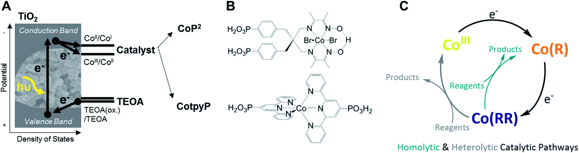 | ||
| Fig. 1 (A) Scheme of the hydrogen evolution and CO2 reduction photocatalytic systems investigated in this work, where the arrows indicate the direction of electrons. (B) Structure of the two molecular catalysts studied. (C) Simplified mechanism of the two molecular catalysts, which include two electron transfer steps in both CotpyP and CoP2.42–44 | ||
Results
We started by focusing on the catalyst CoP2 loaded onto high-surface area mesoporous TiO2. The TiO2 films (∼4 μm thickness) were prepared on glass-FTO substrates with ∼15 nm anatase nanoparticles, following a previously reported procedure (see ESI† for details).64–66 Subsequently, CoP2 was loaded on the TiO2 films by immersing them in a 0.1 mM CoP2 solution of methanol (MeOH) and water (1![[thin space (1/6-em)]](https://www.rsc.org/images/entities/char_2009.gif) :1) for 12 h. The absorption of CoIIIP2 in solution was determined to be 1600 ± 100 M−1 cm−1 at 445 nm in accordance to literature42 (measured in dimethylformamide, DMF, due to the catalysts insolubility in acetonitrile); similar data were obtained in MeOH and MeOH:ACN 1:1. The average amount of loaded catalyst was 90 ± 50 nmol cm−2 of projected area. Following previous reports42,59 on CoP2 and in line with other literature8,61,67,68 on molecular catalyst supported onto mesoporous TiO2, the loading of this TiO2–CoP2 films corresponded approximately to a monolayer of anchored CoP2, the maximum amount of catalyst that can be covalently attached on the surface. This was optimal for the detection of strong and reproducible spectroscopic catalyst signals. Spectroscopic studies were undertaken in acetonitrile to enable the monitoring of charge accumulation on CoP2 in the absence of subsequent proton reduction catalysis.
:1) for 12 h. The absorption of CoIIIP2 in solution was determined to be 1600 ± 100 M−1 cm−1 at 445 nm in accordance to literature42 (measured in dimethylformamide, DMF, due to the catalysts insolubility in acetonitrile); similar data were obtained in MeOH and MeOH:ACN 1:1. The average amount of loaded catalyst was 90 ± 50 nmol cm−2 of projected area. Following previous reports42,59 on CoP2 and in line with other literature8,61,67,68 on molecular catalyst supported onto mesoporous TiO2, the loading of this TiO2–CoP2 films corresponded approximately to a monolayer of anchored CoP2, the maximum amount of catalyst that can be covalently attached on the surface. This was optimal for the detection of strong and reproducible spectroscopic catalyst signals. Spectroscopic studies were undertaken in acetonitrile to enable the monitoring of charge accumulation on CoP2 in the absence of subsequent proton reduction catalysis.
To characterise the redox potentials and the spectroscopic features of the different catalyst oxidation states involved in the catalytic reduction of hydrogen, CoP2 was investigated on mesoporous indium tin oxide (ITO, particle size < 50 nm, film thickness ∼3 μm), employing the same loading strategy as for TiO2.42,61,69 The catalytic mechanism of cobalt diimine–dioximes and related cobalt catalysts is widely agreed to start by two consecutive reductions involving three redox states:42,44 CoIII, CoII and CoI (Fig. 1C), where CoIII is the initial state.43,49,50 The potentials of these two reductions were determined by cyclic voltammetry using ITO-CoP2 as working electrode (Fig. 2A), which compared to ITO alone showed two characteristic reduction waves at ∼ −0.4 and ∼ −0.7 V vs. Normal Hydrogen Electrode (NHE), assigned to the CoIII/CoII and CoII/CoI reductions, respectively. Following these data, the absorption of the three reduced ITO-CoP2 species was determined at three different applied potentials, before and after the observed redox waves, where the catalyst was expected to be predominantly in one of the three oxidation states (Fig. 2B). The experimental spectra were measured using ITO-CoP2 films in ACN containing tetrabutylammonium hexafluorophosphate (TBAPF6, 0.1 M) as supporting electrolyte. Mesoporous ITO was used instead of TiO2 because of its conductivity in the potential range of interest and its lower absorption in the visible range,45,70 therefore allowing a better identification of the absorption features of the different redox species. Fig. 2B also shows the theoretical spectra of different catalyst reduced species, which assume the replacement of the axial bromido ligands by acetonitrile molecules as previously observed in the literature.54,71 These were calculated by time-dependent density functional theory (TD-DFT) combining the hybrid functionals B3LYP and TPSSh and the basis sets 6-31G(d,p) and def2-TZVP, leading to absorption bands with a deviation between the different calculation methods of ∼30 nm (ESI, Table S1†).72,73 As seen in Fig. 2B, the experimental and theoretical results are in good agreement.
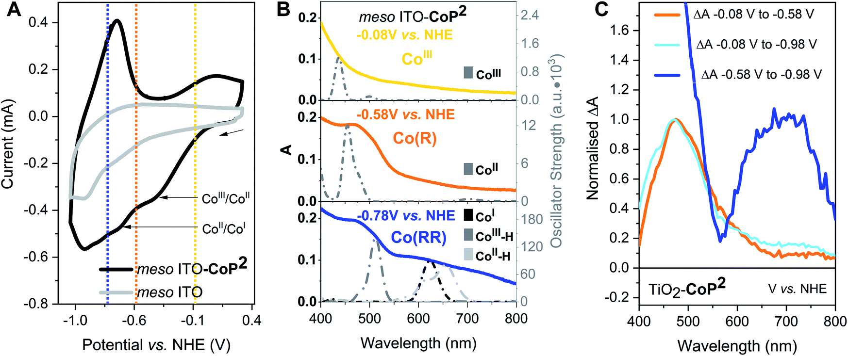 | ||
| Fig. 2 Electrochemical and spectroelectrochemical characterisation of the CoP2 catalyst on ITO and TiO2. (A) Cyclic voltammetry of CoP2 attached to ITO in ACN 0.1 M TBAPF6vs. NHE. (B) Experimental (coloured continuous) and theoretical (grey dotted) steady-state absorption spectra of CoP2 at different potentials. The baseline of the experimental spectra is ITO in ACN 0.1 M TBAPF6. The predicted absorption spectra shown have been obtained from TD-DFT calculations using the hybrid functional B3LYP combined with the basis set 6-31G(d,p). (C) Experimental steady-state absorption changes of TiO2–CoP2 in ACN 0.1 M TBAPF6. Co(R) and Co(RR) stand for mono- and multi-reduced catalyst species, respectively. | ||
The absorption features in the experimental UV-vis range are assigned following the cyclic voltammetry in Fig. 2A and the TD-DFT results and in agreement with the literature:42,44,54–58 CoIII (−0.08 V vs. NHE) absorbs mostly below 400 nm (Fig. 2B top), CoII (−0.58 V vs. NHE) has an absorption band at around 450–500 nm (Fig. 2B middle) and CoI (−0.78 V vs. NHE) has a characteristic absorption between 600–700 nm (Fig. 2B bottom). From these spectra, following the Lambert–Beer law, the absorption coefficients at 700 nm of CoIII, CoII and CoI were determined to be 350 ± 30, 470 ± 30 and 1130 ± 70 M−1 cm−1 respectively (see ESI† for more details). At −0.78 V vs. NHE, the bands at 460 nm and at 600–700 nm are also consistent with the presence of electrochemically reduced hydride species due to traces of water, confirmed by TD-DFT calculations (Fig. 2B and Table S1†). Because of the likely presence of such hydride species at negative potentials, the reduced catalyst species are classified herein as mono-reduced species or Co(R) (i.e. CoII) and multi-reduced species or Co(RR) (i.e., CoI, CoII–H, CoIII–H). The same spectroelectrochemical experiment was repeated with the catalyst on TiO2. Similar absorption trends were observed on TiO2 but at more negative potentials, probably because of the conductivity limitations of the conduction band of TiO2 and/or differences in surface charge (Fig. 2C and S1†). These spectra were used to determine differential spectra for the reduction of this catalyst on both ITO and TiO2 (Fig. 2 and S1†), which are used below to interpret transient absorption (TA) changes under photocatalytic conditions. Control spectroelectrochemical data on bare TiO2 (Fig. S2 and S3†) allowed tracking of electron accumulation in TiO2 conduction band tail states, as we discuss further below. This electron accumulation increases approximately exponentially for applied potentials negative of −0.58 V vs. NHE, as reported previously.74,75
The spectra obtained spectroelectrochemically in the dark (Fig. 2 and S1†) were compared to photoinduced spectral changes obtained under two different light excitation regimes. Firstly, the transient absorption of CoP2 on TiO2 was recorded in the microsecond to second timescale under −0.08 V vs. NHE and strong (1.3 mJ cm−2) 355 nm pulsed laser excitation intensity, allowing direct band gap excitation of TiO2, measured in acetonitrile solution with the addition of 0.1 M TEOA as the hole scavenger and 0.1 M TBAPF6. The resulting transient spectrum measured from 10 μs to 1 s after excitation shows an absorption band peaking at 700 nm (Fig. 3A), whereas the absorption of bare TiO2 under these conditions is relatively flat throughout the 450–900 nm range (Fig. S4†), being characteristic of electrons in the conduction band of TiO2.76,77 The photoinduced absorption signal at 700 nm (Fig. 3A) is long-lived, only decaying by ∼50% on the 1 s timescale of these transient measurements. Secondly, under 5 s steady-state irradiation while applying the same bias (−0.08 V vs. NHE), the same absorption band at 600–700 nm was observed in TiO2–CoP2, as shown in Fig. 3B. This photoinduced band at 700 nm is in excellent agreement with the Co(RR)-minus-Co(R) absorption difference spectrum obtained electrochemically in the dark (Δ(Co(RR) − (Co(R)), (Fig. 2C, S1 and S2†), and is clearly distinct from both the Co(R)-minus-CoIII and Co(RR)-minus-CoIII spectra (Δ(Co(R) − CoIII) and Δ(Co(RR) − CoIII) respectively). It is therefore assigned to the reduction of Co(R) (accumulated starting state of the catalyst under both of these irradiation conditions) leading to the formation of Co(RR). This assignment is supported by further results detailed in the following paragraph. Following this assignment, under these conditions, the absorption of the possible remaining electrons on TiO2 electrons is very likely to be masked by the formation of Co(RR), absorbing above 600 nm, and the depletion of Co(R), bleaching below 500 nm. The spectroelectrochemical signal measured in the dark (determined by subtracting spectra at −0.58 V and −0.98 V vs. NHE) differs significantly from the photoinduced one below 500 nm. This is probably due to contribution, in the dark spectroelectrochemical data, of the reduction of CoIII to Co(R), which can only be electrochemically reduced at more negative potentials than the conduction band simultaneously to the reduction of Co(R) to Co(RR) (Fig. 2B, C and S1†). Evidence from these three different studies therefore suggests that, under photocatalytic conditions at −0.08 V vs. NHE, the first reduced state (Co(R)) accumulates under the aprotic conditions used in this study, with subsequent light pulse further reducing this state transiently to Co(RR). These results also indicate that reduction of Co(R) to Co(RR) can be readily monitored by the appearance of a photoinduced absorption at 700 nm; the latter is therefore taken as the reference wavelength to study Co(RR) formation kinetics on this timescale in our studies below.
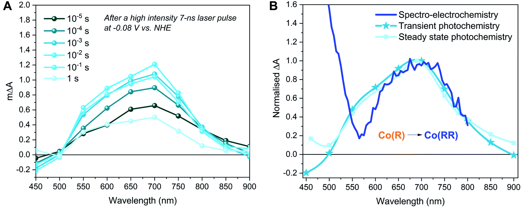 | ||
| Fig. 3 Transient photoinduced absorption spectra and comparison with steady-state spectra both electrochemically induced and under constant irradiation. (A) Transient absorption spectra of TiO2–CoP2 in ACN 0.1 M TEOA 0.1 M TBAPF6 at 1.29 ± 0.04 mJ cm−2 355 nm excitation intensity with 0.8 Hz laser repetition under −0.08 V vs. NHE. (B) Comparison of the difference spectra of TiO2–CoP2 in ACN 0.1 M TBAPF6 0.1 M TEOA after 355 nm excitation at −0.08 V vs. NHE (Photochemistry techniques) and between −0.78 V and −0.98 V vs. NHE in the dark (Spectro-electrochemistry technique). The transient photochemistry signal was measured 10 μs after a high intensity 7 ns laser pulse, while the steady state photochemistry signal was measured after 5 s under constant irradiation. Co(R) and Co(RR) stand for mono- and multi- reduced catalyst species respectively. | ||
To further investigate our assignments, and, in particular, the accumulation and reactivity of the mono-reduced state TiO2–Co(R) under high light intensities in acetonitrile, we monitored the 700 nm transient absorption signal over consecutive measurements (an average of 16 laser pulses) with intervals of ∼3 min between each measurement. If the photogenerated species are short-lived (less than the time lapse between experiments, ∼3 min.), the experiment presents invariable kinetic traces. On the other hand, if the generated species are long-lived (more than ∼3 min.), they accumulate and correspond to the initial state for the subsequent measurement, thus changing the shape of the consecutive signals. Fig. 4A illustrates the changing 700 nm TA dynamics of a fresh sample photoexcited at 355 nm under −0.08 V vs. NHE over time until signal stabilisation. Following our assignment above, the final (stabilised) TA signal (lightest blue in Fig. 4A) corresponds to the laser pulse induced formation of Co(RR) from accumulated Co(R) species. On the other hand, the initial signal (darkest blue in Fig. 4A) exhibits a relatively small photoinduced absorption, with no microsecond growth phase but rather a circa 1 ms decay to zero. This signal, and its decay kinetics, is similar, but smaller in amplitude, than the 700 nm signal of bare TiO2 (Fig. S4 and S5†). To further investigate the identity of these optical signals, the electrons extracted from the photoelectrode were monitored as a transient photocurrent (TPC) signal (Fig. 4B), which consists of a positive current peaking in ∼1 ms after excitation, with this TPC signal being largest for the bare TiO2. These data together indicate that the initial signal (darkest blue) in Fig. 4A corresponds to the photoinduced absorption of electrons in the conduction band of TiO2, with the decay of this signal on the ms timescale resulting primarily from electron extraction to the external circuit. Taking into account that the initial state of the catalyst anchored to TiO2 is CoIII, the reduction in amplitude of this signal relative to bare TiO2 can be assigned to the reduction of CoIII to Co(R), which has been reported to be faster than microseconds.59 We note that this catalyst reduction from CoIII to Co(R) is not expected to give a significant signal at 700 nm (Fig. 2 and S1†), consistent with the initial 700 nm signal being smaller in the presence of catalyst than for bare TiO2. It is also apparent from Fig. 4A that the Co(RR) signal (lightest blue in Fig. 4A) decays within seconds, which is probably related to the reoxidation of Co(RR) to Co(R) by injecting electrons from the catalyst into either the conduction band of TiO2 (observed experimentally as a TPC) or the electrolyte. These data therefore indicate that, under this pulsed laser excitation, Co(R) progressively accumulates on TiO2, resulting in the increasing observation of subsequent transient photoreduction of Co(R) to Co(RR), in agreement with Fig. 3 above and our assignment in the preceding paragraph.
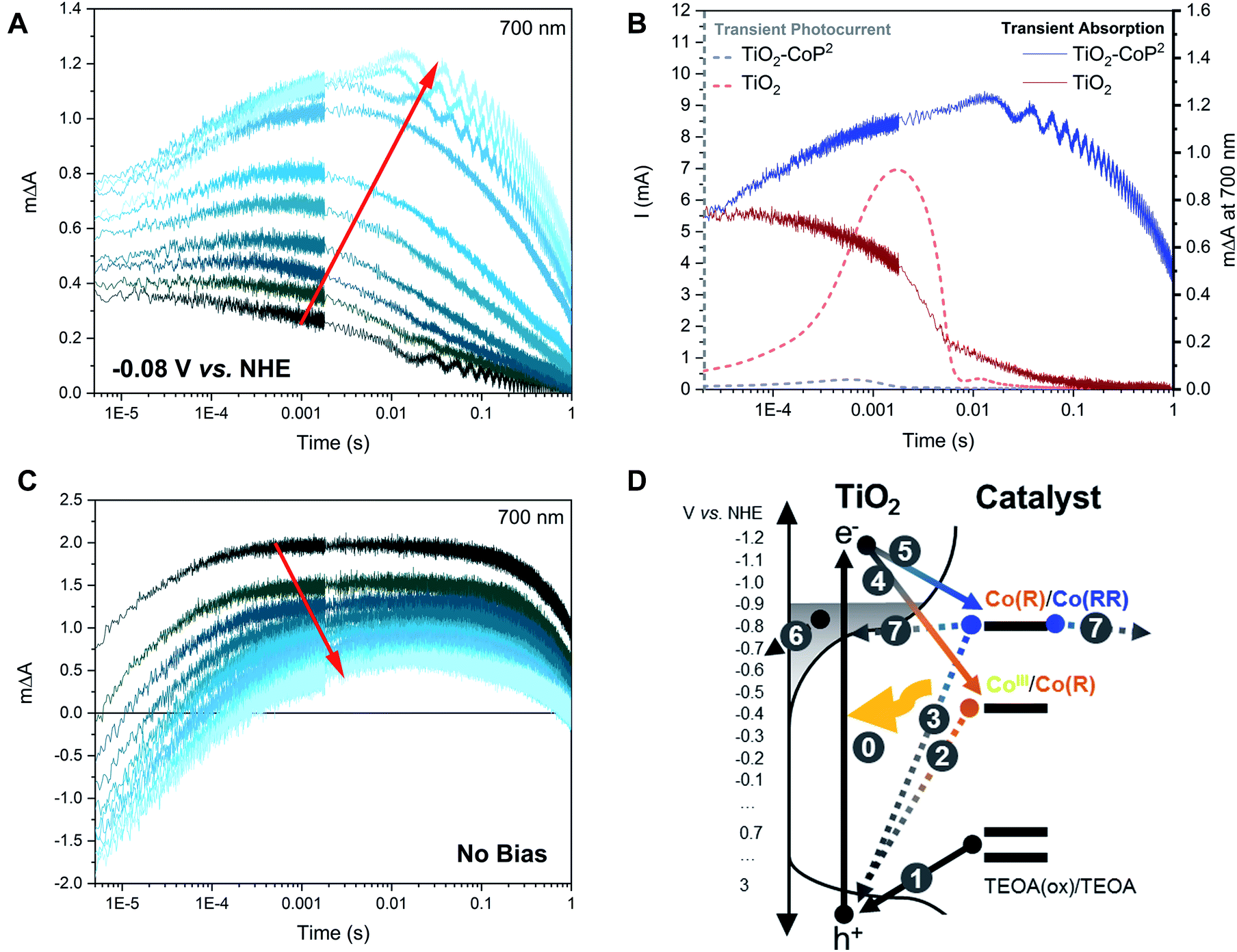 | ||
| Fig. 4 Kinetics at 700 nm of TiO2–CoP2 with (A) applied potential (−0.08 V vs. NHE) in ACN 0.1 M TBAPF6 and 0.1 M TEOA. Consecutive measurements with ∼1.4 mJ cm−2 355 nm excitation, 16 excitation shots averaged per measurement and ∼0.9 Hz laser repetition rate are shown. The darkest signal corresponds to the fresh sample, while the lightest corresponds to the final stable signal chosen for the rest of figures. (B) Overlap between the stabilised transient absorption (TA) and transient photocurrent (TPC) signals of TiO2 and TiO2–CoP2 under −0.08 V vs. NHE in ACN 0.1 M TBAPF6 and 0.1 M TEOA with ∼1.4 mJ cm−2 355 nm excitation. (C) Kinetics at 700 nm of TiO2–CoP2 without applied potential (−0.08 V vs. NHE) in the same conditions. (D) Scheme of the different electron transfer processes identified, where (0) corresponds to excitation of TiO2 with light, (1) corresponds to the scavenging of holes by TEOA, (2) and (3) are recombination processes between the reduced catalyst and TiO2 holes, (4) and (5) are charge transfers from TiO2 to reduce the catalyst, (6) is the removal of electrons from the conduction band of TiO2 under bias, and (7) is the back electron transfer from the reduced catalyst to either the valence band of TiO2 or the electrolyte. Co(R) and Co(RR) stand for mono- and multi- reduced catalyst species respectively. | ||
We now move from studying the accumulation of Co(R) at a fixed bias (−0.08 V vs. NHE), to study the accumulation of reduced species without any applied bias (i.e.: under open circuit conditions), still retaining TEOA as hole scavenger. Applying a bias is an effective way to control the photoelectrode potential (as shown in Fig. 3 and 4A) but is not typically employed in most analogous photocatalytic systems in the literature. In the experiments above, applying a bias at −0.08 V vs. NHE between the valence and the conduction band of TiO2 has been used to minimise the electron density in the conduction band TiO2, but does not significantly oxidise Co(R) due to the low conductivity of the TiO2 at this near-midgap potential.78,79 Upon prolonged light excitation under open circuit conditions, the potential of the TiO2–CoP2 photoelectrode was observed to decrease from ca. −0.08 V to −0.88 V vs. NHE, indicative of increased electron accumulation in the electrode. Fig. 4C shows time-resolved absorption data at 700 nm as a function of pulsed irradiation time analogous to that in Fig. 4A discussed above, but now under these open circuit conditions. It is apparent that these TA kinetics are very distinct from those observed under −0.08 V vs. NHE bias. The initial signal without applied bias (darkest blue, Fig. 4C) is most comparable to the stabilised signal observed under applied bias (lightest blue, Fig. 4A), and therefore assigned, as above, primarily to the reduction of Co(R) to Co(RR) (Fig. 4A). This is indicative of a much quicker accumulation of Co(R) on the surface of TiO2 under open circuit conditions, most likely resulting from the lack of electron extraction to the external circuit induced under bias. Under these open circuit conditions, the amplitude of the positive, long-lived TA signal at 700 nm decreases over consecutive measurements and becomes increasingly negative at early timescales (∼μs) (Fig. 4C). A similar trend is observed when a set of fresh samples are excited with increasing pulse intensities (Fig. S6†). Because Co(RR) is the species that absorbs the strongest at 700 nm compared to other catalyst species and TiO2 electrons, the negative signal at early timescales is most likely due to a bleaching of the absorption of this Co(RR) species. These data are thus compatible with the accumulation of Co(RR) at the TiO2 surface under prolonged irradiation, consistent with the observed shift in open circuit potential to −0.88 V vs. NHE. Under these prolonged irradiation conditions, the negative initial signal can be assigned to rapid (<μs) oxidation of Co(RR) to Co(R) by valence band holes (i.e.: a charge recombination process), with the subsequent appearance at longer times of a positive signal assigned to overall net reduction of Co(R) to Co(RR) by electrons from the conduction band of TiO2. In contrast, a bleach at 450–500 nm is observed at μs under −0.08 V vs. NHE bias without TEOA (Fig. S7†). Considering that at −0.08 V vs. NHE bias Co(R) accumulates (Fig. 3A) and that Co(R) has an absorption peak at ∼470 nm, the bleach at 450–700 nm can be assigned to the recombination of Co(R) with photogenerated holes when a bias is applied but no hole scavenger is added. Therefore, these data (summarised in Fig. 4D and S8†) indicate that both Co(R) and Co(RR) can recombine with photogenerated holes on < μs timescales, with the relative dominance of these two recombination pathways depending on which species accumulates under the conditions studied (i.e. Co(R) at −0.08 V vs. NHE applied bias, and Co(RR) at open circuit potential).
We now turn to a further analysis of the impact of modulating the initial oxidation state of the catalyst on the observed transient kinetics. With this purpose, two different strategies were adopted: (i) the starting population of the catalyst was modulated by varying the applied potential while keeping the same excitation intensity, and (ii) the concentration of photogenerated electrons in the conduction band relative to the catalyst concentration was regulated by varying the excitation intensity while keeping a constant potential below the conduction band of TiO2. Starting at the same conditions as in Fig. 3 (i.e. ∼1.4 mJ cm−2 under −0.08 V vs. NHE), with the catalyst in the Co(R) state as concluded above, first, the light excitation intensity was decreased and, second, a more reducing potential was applied. Fig. 5 shows the effect of these changes on the transient absorption kinetics at 700 nm, with full TA spectra shown in Fig. S9.† When the laser intensity is reduced (as it is apparent in Fig. S10A†), there is a sharp change in kinetics around 1.2 mJ cm−2, with Fig. 5 showing data above and below this threshold (‘high’ and ‘low’ intensity excitation respectively). Above this threshold (high excitation), the transient absorption signal of Co(R) to multi-reduced species Co(RR) is observed, apparent both in the kinetics at 700 nm (Fig. 5A) and the spectrum at 1 ms peaking at 700 nm (Fig. 5B). Below this threshold (low excitation), the amplitude of the 700 nm signal is much less intense and decays faster, comparable to the initial non-stabilised kinetics in Fig. 3A assigned to TiO2 electrons. This weaker, faster decaying signal is also assigned to electron signals of the TiO2, as confirmed by the low excitation 1 ms spectrum in Fig. 5B, where the absorption feature at 700 nm assigned to Co(RR) is now absent, and instead a broad, featureless photoinduced absorption is observed, similar to that of bare TiO2 films. It is apparent that electrons which are photogenerated under these low intensity conditions are thus not capable of reducing Co(R) to Co(RR), attributed to a lack of electron accumulation in TiO2 under these conditions. We note that TiO2 has a distribution of tail states below the conduction band that are likely to trap photogenerated electrons and limit charge transfer to the catalyst at low light intensities, as we discuss in more detail below.80 This switch in transient kinetics from high to low excitation, turning off Co(R) reduction to Co(RR), was reversed by applying a more negative applied potential to fill up the trap states in the conduction band electrochemically (Fig. 5A and S10B†). Under these conditions, at −0.88 V vs. NHE and low excitation, the kinetics at 700 nm are again indicative of Co(R) reduction to Co(RR). These data illustrate that the accumulation of reduced catalyst species in these samples can be readily modulated by both the excitation intensity and applied bias, with resultant large changes in the observed electron transfer kinetics.
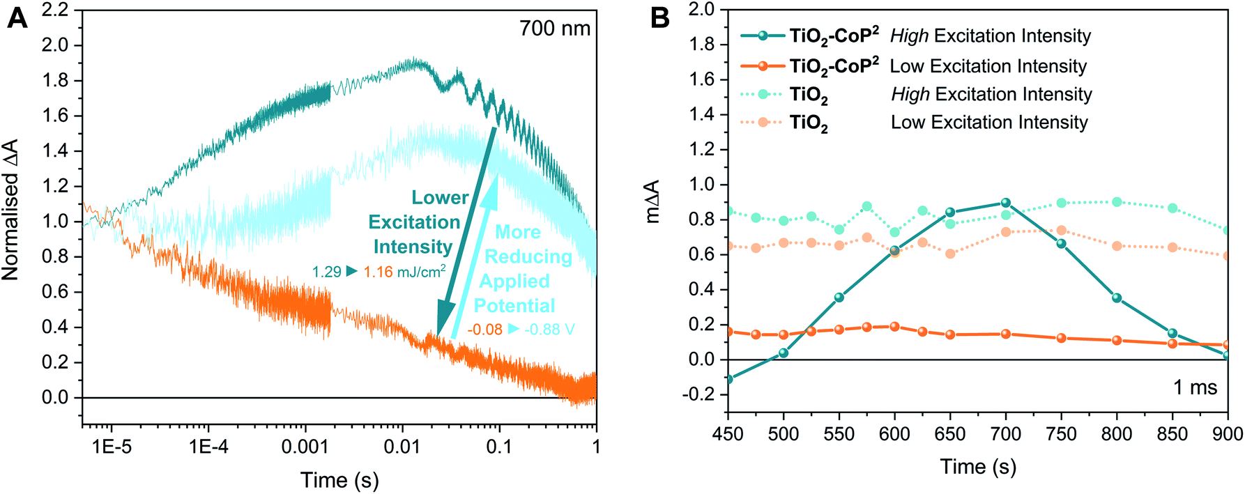 | ||
| Fig. 5 Dependency of charge accumulation in TiO2–CoP2 on bias and light intensity. (A) Kinetics at 700 nm of TiO2–CoP2 under different excitation intensities and applied bias. (B) Spectra of TiO2–CoP2 and TiO2 at different excitation intensities: 1.16 ± 0.03 mJ cm−2 (low) and 1.29 ± 0.04 mJ cm−2 (high) at a time delay of 1 ms. Experimental conditions: ACN 0.1 M TBAPF6 and 0.1 M TEOA under bias excited with a 355 nm laser pump (0.8 Hz repetition rate). | ||
Employing the transient data in Fig. 5, we estimated the quantum efficiency for electron transfer from TiO2 to Co(R). Given that the time-resolved signal at 700 nm has been assigned to the one-electron reduction of Co(R) to Co(RR), the quantum yield of electron transfer from TiO2 to the mono-reduced catalyst to form Co(RR) can be estimated from the maximum absorption change at 700 nm (at ∼10 ms from excitation), the incident laser pulse energy and the absorption extinction coefficients at 700 nm deduced from the spectroelectrochemistry in the dark (see ESI†). The TA signal of bare TiO2 at 1.16 mJ cm−2 under −0.08 V vs. NHE, which corresponds to the absorption of electrons in the conduction band of TiO2, as discussed previously, has been taken as baseline. Table 1 presents the calculated apparent quantum yields as a function of reducing excitation intensities and bias, corresponding to the results in Fig. 5. It is apparent that the quantum yield for Co(R) reduction under high excitation conditions and −0.08 V vs. NHE is remarkably high (44%), indicative of high efficiency of this reaction. At low excitation conditions and −0.08 V vs. NHE, the efficiency of this reaction reduced to near zero. This efficiency is partially recovered at −0.88 V vs. NHE (22%). At this reducing potential, the quantum yield does not improve with increasing light intensity, being 0.06 ± 0.01 at 1.44 ± 0.03 mJ cm−2, which is lower than under −0.08 V vs. NHE and indicates the saturation effects and/or the degradation of the reduced catalyst species under these reducing conditions.50,81 We note that it was not possible to record time-resolved spectra at such reducing potentials due to the degradation of reduced species (within ∼1 h), assuming that the catalyst degrades when the catalyst signal at 700 nm is not observed any longer. These data emphasise the remarkable large dependence of efficiency of Co(R) reduction to measurement conditions.
| Conditions | Quantum yield (Co(R) → Co(RR)) at ΔA700 nm,max. |
|---|---|
| 1.29 mJ cm−2 | 44 ± 6% |
| −0.08 V vs. NHE | |
| 1.16 mJ cm−2 | 1 ± 6% |
| −0.08 V vs. NHE | |
| 1.16 mJ cm−2 | 22 ± 2% |
| −0.88 V vs. NHE |
To confirm that the charge accumulation observed in CoP2 is relevant for catalysis and is enough to reduce protons and produce hydrogen, 10% of water was added to the acetonitrile solutions used in all the previous measurements. In the literature, the catalyst CoP2 has been reported to evolve H2 in slightly acidic water when co-attached with a Ru(II)-based dye on TiO2 and exciting the ruthenium dye at >420 nm.51 Here, the 4 μm-thick TiO2 films loaded with CoP2 used above were shown to produce H2 when immersed in ACN:H2O 9:1 0.1 M TEOA 0.1 M TBAPF6 under constant UV-vis light irradiation (Fig. S11†). Taking the H2-reduction cobaloxime catalyst [CoIIICl(dmgH)2(pyridyl-4-hydrophosphonate)]−47 attached on mesoporous TiO2 as a reference (see SI for details), the catalytic activity of CoP2 in acetonitrile with 10% water was observed to remain proportionally the same as in pure water. Under −0.08 V vs. NHE, the TA signal corresponding to the reduction of Co(R) to Co(RR) in acetonitrile (Fig. 3 and 5) was also detected in ACN:H2O 9:1 (see Fig. S12†), showing that Co(R) and Co(RR) species are still formed in catalytic conditions. In ACN:H2O 9:1, the kinetics at 700 nm decayed faster than in pure ACN, which indicates that Co(RR) species are less long-lived in water, consistent with this intermediates driving proton reduction in this electrolyte. This evidence therefore shows that the absorption features of CoP2 in ACN remain similar when water is added, and that both Co(R) and Co(RR) species can be catalytic intermediates in the H2-production activity of CoP2.
From all the results above, we have inferred that charge accumulation is highly dependent on the relative energy of photoexcited electrons in TiO2 with respect to the potentials of CoP2's redox transitions. In order to further investigate the effect of the redox potential position on charge accumulation, the multi-redox molecular catalyst CotpyP,61,62 which is one of the state-of-the-art CO2-reduction catalysts82 and has more negative reductive potentials than CoP2, was also studied on TiO2 in the same aprotic and hole scavenging conditions as CoP2 (i.e., ACN and 0.1 M TEOA) (Fig. 6). The catalyst CotpyP was loaded on TiO2 in a similar way as CoP2 (see ESI† for more details), and its redox potentials in acetonitrile were roughly estimated from the cyclic voltammetry on ITO-CotpyP and TiO2–CotpyP (Fig. S13A†): E1/2, Co(III/II) ≈ −0.78 V vs. NHE and E1/2, Co(II/I) ≈ −1.2 V vs. NHE. The spectra of the different oxidation state species was studied by spectroelectrochemistry analogously to the CoP2: the steady-state absorption of TiO2–CotpyP was measured at different applied potentials and two different characteristic absorption spectra were identified at the two redox potentials, which were consequently assigned to the formation of CoII and CoI from CoIII (Fig. 6B and S13B†). As with CoP2, singly- and multi-reduced species of CotpyP were labelled as Co(R) and Co(RR) respectively, assuming CoIII as the starting oxidation state of the metal centre. Photoinduced transient absorption was measured under similar conditions to those where the accumulation of Co(R) and the formation of Co(RR) are photoinduced in TiO2–CoP2, with ∼1.4 mJ cm−2 355 nm excitation both without bias and under −0.58 V vs. NHE, where the catalyst could not be electrochemically reduced to CoIII. In contrast to TiO2–CoP2, the transient kinetics in photoexcited TiO2–CotpyP were observed to be very similar both with and without applied bias (Fig. S14†). The transient spectrum was then matched with the electrochemically induced spectra, obtained in the dark following the same procedure detailed previously for CoP2. The photoinduced transient absorption overlaps with the electrochemically induced absorption difference between −0.08 and −2.28 V vs. NHE in the dark, which corresponds to the transition CoIII → Co(RR) (Fig. 6). Thus, upon light excitation under −0.58 V vs. NHE, the observed signal is indicative of two consecutive electron transfers which take place before ∼15 microseconds from TiO2 to the CotpyP, reducing CoIII to Co(RR). Following the same procedure as with CoP2 (see ESI†), the apparent quantum yield for the formation of multi-reduced species from CoIII is 20 ± 10%. This contrasts with TiO2–CoP2 under bias and light excitation, where Co(R) is observed to accumulate during the TA measurements. This difference in charge accumulation can be attributed to the relative positions of the redox states of these catalysts with respect to the conduction band of TiO2. The observation of two electron transfers to CotpyP is particularly striking given its negative reduction potentials, as we discuss further below. In any case, it is apparent that the more negative reduction potentials for CotpyP relative to CoP2 prevent the steady state accumulation of reduced catalyst states, consistent with our analyses of CoP2 above. The complete dataset is available at http://zenodo.org with the identifier 10.5281/zenodo.4268218.
 | ||
| Fig. 6 Transient and steady state spectroelectrochemical characterisation of the CO2-reduction catalyst CotpyP on TiO2 in ACN 0.1 M TBAPF6 and 0.1 M TEOA. (A) Scheme of the photocatalytic system, where the arrows indicate the direction of electron transfers. (B) Comparison between photoinduced transient spectra (after ∼1.4 mJ cm−2 355 nm excitation with 0.8 Hz laser repetition rate under −0.58 V vs. NHE) and electrochemically-induced steady state spectra of TiO2–CotpyP in ACN 0.1 M TBAPF6 0.1 M TEOA. | ||
Discussion
In photodriven catalysis, multi-redox catalysis is particularly challenging due to the need to drive multiple, and typically increasingly energetically challenging, reduction/oxidation steps. In such studies, the accumulation of intermediate oxidation states of the catalyst is often needed, but can result in recombination losses from subsequent photoexcitations. In this study of catalyst functionalised on TiO2 films, we employ a hole scavenger to remove photogenerated holes and an aprotic solvent to minimise the presence of water and focus on the accumulation of different reduced species in the absence of significant proton reduction catalysis. We show that varying the applied potential and/or the light intensity are both effective approaches to control the electron density in TiO2 necessary to induce electron transfer to the catalyst. This thereby regulates both the oxidation state of the catalyst accumulated under prolonged irradiation, and the observed electron transfer kinetics. By using this approach, our results suggest that it is possible to observe selectively electron transfer to reduced states of two different multi-redox molecular catalysts to aid the design of efficient electrode or photocatalytic systems employing TiO2 as photoabsorber.Molecular catalysts exhibit well defined energy states and redox potentials.83 In contrast, TiO2 exhibits not only a conduction and valence band separated by a bandgap but also a significant density of tail states extending from the band edges into its bandgap,74,75 as presented schematically in Fig. 7. This is observed in our control spectroelectrochemical data for TiO2 in Fig. S2A† and illustrated in Fig. S3.† Consideration of charge trapping into, and accumulation in these tail states has been shown to be critical to understanding the function of DSSCs,65,80,84–90 and is also likely to be critical to understanding photocatalytic systems employing TiO2. For example, trap filling resulting from increased electron accumulation in the conduction band tail states has been shown to have multiple impacts, including increasing effective electron mobility by orders of magnitude, and also increasing the energy, and therefore reactivity, of accumulated electrons.60,65,84–86,90,91 In addition, the energy of the conduction band states and, thus, that of accumulated electrons varies with pH and the presence of cations;88,92–94 in particular, the flat-band potentials of TiO2 in water compared to acetonitrile differ by around 1.2 V vs. NHE, leading to a more pronounced charge trapping and energy loss in water.94,95 Therefore, following the initial generation of relatively energetic electrons by UV excitation, the subsequent relaxing/trapping of electrons on ps–ns timescales will result in a progressive loss of electron energy, which will also result in time dependence of electron reactivity following photoexcitation.
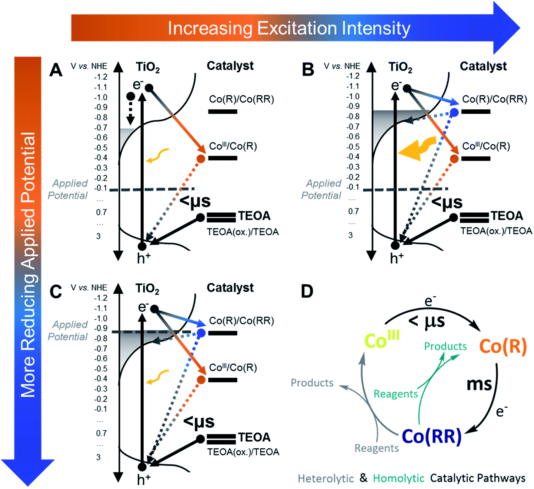 | ||
| Fig. 7 Scheme illustrating the processes occurring in TiO2–CoP2 at different excitation intensities and applied potentials. Representation of TiO2–CoP2 in ACN 0.1 M TBAPF6 and 0.1 M TEOA (A) under −0.08 V vs. NHE excited with a ∼1.2 mJ cm−2 355 nm laser pump (0.8 Hz repetition rate), (B) after increasing the excitation intensity by ∼200 mJ cm−2, and (C) after decreasing the potential to −0.88 V vs. NHE. (D) Simplified scheme of the catalytic mechanism and its timescales, where CoIII is the initial catalyst state (with an oxidation number of 3), Co(R) stands for mono-reduced catalyst intermediates, and Co(RR) corresponds to multi-reduced catalyst species. The arrows in A–C indicate the direction of electron transfers. | ||
For the proton reduction catalyst CoP2, the time-resolved absorption studies indicate that, upon excitation, different reduced states of the catalyst can accumulate on the surface of TiO2, depending upon whether an external bias is applied or not (Fig. 4). Most of the experiments in this study were carried out under intra-bandgap applied bias, which is distinct from the open circuit conditions present in most photocatalytic systems employing hole/electron scavengers. As shown herein, this allows a better control of the oxidation state of the system for functional characterisation. Under −0.08 V vs. NHE (an intra-bandgap potential), the mono-reduced species Co(R) was seen to accumulate under irradiation. This is consistent with the energetic alignment of the CoIII/Co(R) redox couple with respect to the valence band of TiO2 and the distribution of tail states in the TiO2's conduction band, as illustrated in Fig. 7. The low conductivity of TiO2 at this near midgap potential and the bulkiness of the catalyst probably prevents Co(R) from being electrochemically oxidised to CoIII by either the TiO2 or charge transfer between neighbouring catalyst molecules. Because Co(R) accumulates at −0.08 V vs. NHE, subsequent light excitation leads to the reduction of Co(R) to Co(RR), which corresponds to the signal observed with TA (Fig. 3). The kinetic signal assigned to the formation of Co(RR) peaks at around 1 ms and decays from milliseconds to seconds, the latter being compatible with the back electron transfer from the catalyst to TiO2 and its equilibration with the applied potential. Under this bias condition, Co(R) accumulation and subsequent reduction to Co(RR) is only observed after relatively high intensity photoexcitation, whilst CoIII reduction to Co(R) is observed under low intensity irradiation (Fig. 5), as shown in Fig. 7. This behaviour is assigned to photoinduced electron accumulation both on the catalyst (as Co(R) states) and in TiO2 conduction band tail states.74,75 Long-lived Co(RR) species are only obtained upon irradiation in the presence of such electron accumulation. This was further confirmed by applying a more negative potential (−0.88 V vs. NHE). At this reducing potentials, all the catalyst molecules on the electrode surface are electrochemically forced in the dark into the mono-reduced state Co(R) and the tail states in TiO2 are filled up, facilitating further reduction to Co(RR) upon excitation, independent of irradiation intensity. The formation of multi-reduced species, necessary for catalysis, is therefore enhanced at high light intensity suggesting that such systems may be particularly effective under concentrated sunlight.
In contrast to applying a bias, under open circuit conditions with light irradiation, multi-reduced species Co(RR) were observed to accumulate, and the degree of accumulation depended on the presence of the hole scavenger. These conditions are more relevant for comparison to analogous photocatalytic systems reported for water oxidation,85,96–99 water reduction18,100–103 or CO2 reduction,45,104,105 mostly investigated without any bias being applied electrochemically. In many cases, the catalytic activity of molecular catalysts assembled on photosensitised electrodes has been reported to be better than when the components are separately dissolved in solution.50,85,96,97,99,100,102,103,106,107 From the above results, the improved performance of assembled systems can be attributed, at least in part, to the ability of TiO2 to accumulate long-lived electrons, which is an advantage that most semiconductor oxides may have when used as photosensitisers compared to molecular dyes. Furthermore, this evidence is in accordance with that reported on dye-sensitised solar cells and electrodes. For these, the recombination kinetics between injected electrons in the conduction band of TiO2 and a photo-oxidised dye at the surface crucially depends on the electron density in TiO2, which in turn is related to light excitation energy and the tail-state distribution in the material.65,80,85–87,89,90 The trap state distribution limits electron transfer to the semiconductor surface, which is an undesired process in dye-sensitised solar cells, but it is an essential step in photocatalysis.
Compared to the catalyst CoP2, singly-reduced species of the CO2-reduction catalyst CotpyP on TiO2 do not build up at the surface under intra-bandgap bias even upon high intensity excitation. In contrast, a double electron transfer is observed to take place from the semiconductor to the molecular catalyst within microseconds under light excitation (Fig. 6 and scheme in Fig. S15†). The double reduction is most likely due to the initially photoexcited electrons in TiO2 having relatively high energy (due to the 355 nm excitation employed), with enough driving force to drive these reductions. This rapid double reduction of CotpyP, which was not observed for CoP2, could be attributed to direct bonding of the phosphonate binding group to the conjugated terpyridine ligand in CotpyP; in contrast for CoP2, the phosphonate group is spatially separated from the redox active centre, significantly reducing the electronic coupling for electron transfer from the TiO2 surface.60 This is also in accordance with our observations above on TiO2–CoP2 under the same high excitation intensity (Fig. 5), where we also observe that TiO2 has the ability to transfer electrons to catalyst states above the conduction band when sub-bandgap trap states are filled up. In contrast to CoP2, no reduced CotpyP species were observed to accumulate on TiO2–CotpyP films after excitation, attributed to CotpyP having more reducing potentials than CoP2. Once doubly reduced by photoexcitation, CotpyP(RR) is reoxidised to CotpyP within 1 s, either by reduction of the electrolyte or by back electron transfer to the TiO2 CB. The CO2 reduction efficiency of catalyst-semiconductor assemblies is usually related to the high overpotential of the catalyst, which reduces the driving force for electron transfer from the semiconductor to the catalyst, and relates well to the low electron transfer quantum efficiency calculated for the double photoreduction of CotpyP.61,62,104,105 Consequently, the above results for CotpyP on TiO2 indicate that CO2 reduction activity may be limited by the efficiency of the initial photoreduction, and also by the lack of accumulation of reduced species, caused by back electron transfer from the catalyst to the semiconductor as the catalyst and semiconductor Fermi levels equilibrate.
A further implication of the negative potential of reduced catalyst species is their reactivity. Reduced catalyst species can undergo irreversible degradation, which was detected in the study herein for both catalysts under highly reducing applied biases following the disappearance of the well-defined Co(RR) signal. This is in agreement with previous experimental and theoretical studies,39,62 where it was observed that, when the CoP2 catalyst is in its CoI state (included herein within the label Co(RR)), it is more likely to degrade. Secondly, our data indicate that doubly-reduced species Co(RR) can recombine with photogenerated holes in the valence band of TiO2 faster than microseconds and can inject electrons back to the conduction band in milliseconds. Similar biphasic recombination kinetics have also been reported by Reynal et al. for TiO2–CoP2 in an aqueous solution.59,60 These Co(RR) species recombine with photogenerated holes faster than microseconds (detected as a strong bleach signal at 700 nm formed on sub-microsecond timescales in Fig. 4C and S6†). On slower timescales, Co(RR) can also transfer electrons back to the conduction band of the semiconductor or the electrolyte shortly after being formed. On the other hand, Co(R) species also recombine with valence band holes, as observed from the lower amplitude at 700 nm of fresh TiO2–CoP2 samples (Fig. 4A) with respect to the corresponding signal in TiO2 under bias (Fig. S5†), and from the bleach at 450–500 nm when no TEOA is used under −0.08 V vs. NHE (Fig. S7†). This evidence is in agreement with the recombination of photogenerated charges in previous literature on inorganic-organic photochemical systems or molecular donor–acceptor dyads.41,91,99,107,108 In the photo(electro)catalytic systems studied herein, formed by molecular catalysts attached on mesoporous TiO2 films working as photoabsorber material, recombination of reduced catalyst species with valence band holes is at least three orders of magnitude faster than electron transfer to the catalyst and it is therefore expected to be one of the main causes of solar-to-hydrogen efficiency loss. The efficiency loss due to recombination despite the presence of a sacrificial electron donor might be related to a low accessibility of the sacrificial donor to the TiO2 surface, which has been measured to have a high catalyst surface coverage.
The slow formation of multi-reduced species Co(RR) in TiO2–CoP2 (Fig. 5) occurs in hundreds of microseconds to milliseconds, a similar timescale as proton diffusion and hydrogen evolution.25,50,95 The timescale where the Co(RR) formation signal reaches its maximum (∼10 ms) is comparable to that of the slowest step of water oxidation in PSII in natural photosynthesis systems. We interpret the charge accumulation kinetics of molecular catalysts by taking the oxygen evolution cluster (OEC) in PSII as a blue print, where the enzymatic scaffold plays a crucial role protecting the metal active site from unwanted reactions and substrates and stabilising charges through proton-coupled reactions, hydrogen bonds and van-der-Waals interactions. In the case of the OEC in PSII, the first step is known to be the fastest step (<μs), the second and third occur in microseconds, while the last one is the slowest with lifetimes of milliseconds.27–33 Taking into account the similarities with PSII, we hypothesise that the slow kinetics of consecutive electron transfers compared to the first electron transfer in both CoP2 and CotpyP might minimise the time that the highly reactive and unstable intermediates (i.e., Co(RR) species) are exposed to the solution, hence decreasing the probability of catalyst degradation. In artificial catalysts as in PSII, an optimal synchronisation between charge transfer and substrate diffusion may therefore minimise the exposure of reactive species and improve the overall catalytic performance.
Conclusions
Transient absorption spectroscopy and steady-state spectroelectrochemical techniques have been employed to study the kinetics of photogenerated electrons in molecular catalyst-TiO2 photo(electro)catalytic systems for proton and CO2 reduction. Consecutive electron transfers from the TiO2 are observed to induce charge accumulation in the catalyst in the form of multi-reduced species. We show that the oxidation state of the catalyst under steady-state irradiation conditions could be controlled by regulating the applied bias and the light intensity. In aprotic solvents and under illumination, in the proton reduction system TiO2–CoP2, different singly- or multi-reduced species accumulate on TiO2 over time either with or without applied bias, depending on the Fermi level of the semiconductor. In contrast, long-term charge accumulation in acetonitrile is not observed in the CO2-reduction catalyst CotpyP on TiO2, which has more reducing potentials, attributed to back electron transfer to the conduction band of TiO2. Charge transfer to the catalyst CoP2 is shown to depend on the electron density of TiO2 and tail states filling, while multi-reduced catalyst species are observed to be formed on slower timescales than mono-reduced species. Because multi-redox charge transfer can be slow, both the ease of TiO2 to accumulate electrons and the accumulation of singly reduced species are fundamental to form multi-reduced species. However, recombination of such reduced species with both conduction band and valence band states directly competes with charge accumulation and it is likely to severely limit multi-redox catalysis in such systems, as it is shown for both CoP2 and the CO2-reduction catalyst CotpyP. Thus, because of the contrast between the ability to retain electrons in the conduction band of TiO2 and limitations in hole scavenging and recombination, when systems based on molecular catalysts attached to TiO2 are used as photoelectrodes, interfaces need to be rectifying to block valence band hole recombination in order to allow charge accumulation at the catalyst.Conflicts of interest
There are no conflicts to declare.Acknowledgements
J. D. and L. F. gratefully acknowledge funding from support by KAUST under the grant agreement number OSR-2018-CRG7-3749.2. C. B-G acknowledges DTP funding from EPSRC. C. A. M. acknowledges financial support from the European Research Council H2020 project A-LEAF (732840). A. E. acknowledges the German National Academy of Sciences Leopoldina for a postdoctoral fellowship (LPDS 2018-04). J. W., J. W. and E. R. were supported by the Christian Doppler Research Association and the OMV Group and D. A.-G. by an EPSRC PhD DTA studentship (EP/M508007/1). R. S. would like to acknowledge funding from the EPSRC through the Doctoral Partnership fund (1855454). We also thank Dr Wenxing Yang for the useful discussions.References
- T. J. Meyer, Nat. Chem., 2011, 3, 757–758 CrossRef CAS.
- E. E. Benson, C. P. Kubiak, A. J. Sathrum and J. M. Smieja, Chem. Soc. Rev., 2009, 38, 89–99 RSC.
- N. S. Lewis and D. G. Nocera, Proc. Natl. Acad. Sci. U. S. A., 2006, 103, 15729–15735 CrossRef CAS.
- K. E. Dalle, J. Warnan, J. J. Leung, B. Reuillard, I. S. Karmel and E. Reisner, Chem. Rev., 2019, 119, 2752–2875 CrossRef CAS.
- I. McConnell, G. Li and G. W. Brudvig, Chem. Biol., 2010, 17, 434–447 CrossRef CAS.
- A. J. Cowan and J. R. Durrant, Chem. Soc. Rev., 2013, 42, 2281–2293 RSC.
- N. Weder, B. Probst, L. Sévery, R. J. Fernández-Terán, J. Beckord, O. Blacque, S. D. Tilley, P. Hamm, J. Osterwalder and R. Alberto, Catal. Sci. Technol., 2020, 10, 2549–2560 RSC.
- J. J. Leung, J. Warnan, D. H. Nam, J. Z. Zhang, J. Willkomm and E. Reisner, Chem. Sci., 2017, 8, 5172–5180 RSC.
- J. S. Lee, D. I. Won, W. J. Jung, H. J. Son, C. Pac and S. O. Kang, Angew. Chem., Int. Ed. Engl., 2017, 56, 976–980 CrossRef CAS.
- B. Zhang and L. Sun, Chem. Soc. Rev., 2019, 48, 2216–2264 RSC.
- N. Best, Research-Cell Efficiency Chart, https://www.nrel.gov/pv/cell-efficiency.html, June 2019 Search PubMed.
- S. Gunes, H. Neugebauer and N. S. Sariciftci, Chem. Rev., 2007, 107, 1324–1338 CrossRef.
- P. V. Kamat, J. Phys. Chem. C, 2008, 112, 18737–18753 CrossRef CAS.
- A. Hagfeldt, G. Boschloo, L. Sun, L. Kloo and H. Pettersson, Chem. Rev., 2010, 110, 6595–6663 CrossRef CAS.
- M. A. Green, A. Ho-Baillie and H. J. Snaith, Nat. Photonics, 2014, 8, 506–514 CrossRef CAS.
- T. Hisatomi, J. Kubota and K. Domen, Chem. Soc. Rev., 2014, 43, 7520–7535 RSC.
- M. D. Symes, Y. Surendranath, D. A. Lutterman and D. G. Nocera, J. Am. Chem. Soc., 2011, 133, 5174–5177 CrossRef CAS.
- D. L. DuBois, Inorg. Chem., 2014, 53, 3935–3960 CrossRef CAS.
- K. Sivula and R. van de Krol, Nat. Rev. Mater., 2016, 1, 15010 CrossRef CAS.
- L. Steier and S. Holliday, J. Mater. Chem. A, 2018, 6, 21809–21826 RSC.
- J. W. Ager, M. R. Shaner, K. A. Walczak, I. D. Sharp and S. Ardo, Energy Environ. Sci., 2015, 8, 2811–2824 RSC.
- S. Wang, A. Aster, M. Mirmohades, R. Lomoth and L. Hammarstrom, Inorg. Chem., 2018, 57, 768–776 CrossRef CAS.
- M. Mirmohades, S. Pullen, M. Stein, S. Maji, S. Ott, L. Hammarstrom and R. Lomoth, J. Am. Chem. Soc., 2014, 136, 17366–17369 CrossRef CAS.
- C. Costentin and J.-M. Savéant, ChemElectroChem, 2014, 1, 1226–1236 CrossRef CAS.
- V. Artero and J. M. Savéant, Energy Environ. Sci., 2014, 7, 3808–3814 RSC.
- L. Duan, F. Bozoglian, S. Mandal, B. Stewart, T. Privalov, A. Llobet and L. Sun, Nat. Chem., 2012, 4, 418–423 CrossRef CAS.
- J. Barber, Chem. Soc. Rev., 2009, 38, 185–196 RSC.
- F. A. Armstrong, Philos. Trans. R. Soc. London, Ser. B, 2008, 363, 1263–1270 CrossRef CAS ; discussion 1270.
- F. A. Armstrong and J. Hirst, Proc. Natl. Acad. Sci. U. S. A., 2011, 108, 14049–14054 CrossRef CAS.
- N. Cox and J. Messinger, Biochim. Biophys. Acta, 2013, 1827, 1020–1030 CrossRef CAS.
- M. Karge, K.-D. Irrgang and G. Renger, Biochemistry, 1997, 36, 8904–8913 CrossRef CAS.
- G. Renger, Photosynth. Res., 2007, 92, 407–425 CrossRef CAS.
- G. Renger, J. Photochem. Photobiol., B, 2011, 104, 35–43 CrossRef CAS.
- H. Y. Chen and S. Ardo, Nat. Chem., 2018, 10, 17–23 CrossRef CAS.
- S. Ardo, D. Achey, A. J. Morris, M. Abrahamsson and G. J. Meyer, J. Am. Chem. Soc., 2011, 133, 16572–16580 CrossRef CAS.
- V. Saavedra Becerril, E. Sundin and M. Abrahamsson, J. Phys. Chem. C, 2018, 122, 25822–25828 CrossRef CAS.
- W. Song, A. Ito, R. A. Binstead, K. Hanson, H. Luo, M. K. Brennaman, J. J. Concepcion and T. J. Meyer, J. Am. Chem. Soc., 2013, 135, 11587–11594 CrossRef CAS.
- S. Karlsson, J. Boixel, Y. Pellegrin, E. Blart, H.-C. Becker, F. Odobel and L. Hammarström, J. Am. Chem. Soc., 2010, 132, 17977–17979 CrossRef CAS.
- K. J. Elliott, A. Harriman, L. Le Pleux, Y. Pellegrin, E. Blart, C. R. Mayer and F. Odobel, Phys. Chem. Chem. Phys., 2009, 11, 8767–8773 RSC.
- L. Hammarstrom, Acc. Chem. Res., 2015, 48, 840–850 CrossRef.
- M. P. O'Neil, M. P. Niemczyk, W. A. Svec, D. Gosztola, G. L. Gaines III and M. R. Wasielewski, Science, 1992, 257, 63–65 CrossRef.
- N. M. Muresan, J. Willkomm, D. Mersch, Y. Vaynzof and E. Reisner, Angew. Chem., Int. Ed. Engl., 2012, 51, 12749–12753 CrossRef CAS.
- J. L. Dempsey, B. S. Brunschwig, J. R. Winkler and H. B. Gray, Acc. Chem. Res., 2005, 42, 1995–2004 CrossRef.
- M. R. Scherer, N. M. Muresan, U. Steiner and E. Reisner, Chem. Commun., 2013, 49, 10453–10455 RSC.
- T. E. Rosser and E. Reisner, ACS Catal., 2017, 7, 3131–3141 CrossRef CAS.
- F. Lakadamyali, A. Reynal, M. Kato, J. R. Durrant and E. Reisner, Chem.–Eur. J., 2012, 18, 15464–15475 CrossRef CAS.
- F. Lakadamyali and E. Reisner, Chem. Commun., 2011, 47, 1695–1697 RSC.
- Y. Pellegrin and F. Odobel, C. R. Chim., 2017, 20, 283–295 CrossRef CAS.
- M. Razavet, V. Artero and M. Fontecave, Inorg. Chem., 2005, 44, 4786–4795 CrossRef CAS.
- V. Artero, M. Chavarot-Kerlidou and M. Fontecave, Angew. Chem., Int. Ed. Engl., 2011, 50, 7238–7266 CrossRef CAS.
- J. Willkomm, N. M. Muresan and E. Reisner, Chem. Sci., 2015, 6, 2727–2736 RSC.
- P. A. Jacques, V. Artero, J. Pécaut and M. Fontecave, Proc. Natl. Acad. Sci. U. S. A., 2009, 106, 20627–20632 CrossRef CAS.
- N. Kaeffer, M. Chavarot-Kerlidou and V. Artero, Acc. Chem. Res., 2015, 48, 1286–1295 CrossRef CAS.
- A. Bhattacharjee, M. Chavarot-Kerlidou, J. L. Dempsey, H. B. Gray, E. Fujita, J. T. Muckerman, M. Fontecave, V. Artero, G. M. Arantes and M. J. Field, Chemphyschem, 2014, 15, 2951–2958 CrossRef CAS.
- X. Hu, B. S. Brunschwig and J. C. Peters, J. Am. Chem. Soc., 2007, 129, 8988–8998 CrossRef CAS.
- T. Lazarides, T. McCormick, P. Du, G. Luo, B. Lindley and R. Eisenberg, J. Am. Chem. Soc., 2009, 131, 9192–9194 CrossRef CAS.
- P. Du, J. Schneider, G. Luo, W. W. Brennessel and R. Eisenberg, Inorg. Chem., 2009, 48, 4952–4962 CrossRef CAS.
- W. Q. Liu, T. Lei, S. Zhou, X. L. Yang, J. Li, B. Chen, J. Sivaguru, C. H. Tung and L. Z. Wu, J. Am. Chem. Soc., 2019, 141, 13941–13947 CrossRef CAS.
- A. Reynal, F. Lakadamyali, M. A. Gross, E. Reisner and J. R. Durrant, Energy Environ. Sci., 2013, 6, 3291 RSC.
- A. Reynal, J. Willkomm, N. M. Muresan, F. Lakadamyali, M. Planells, E. Reisner and J. R. Durrant, Chem. Commun., 2014, 50, 12768–12771 RSC.
- J. J. Leung, J. Warnan, K. H. Ly, N. Heidary, D. H. Nam, M. F. Kuehnel and E. Reisner, Nat. Catal., 2019, 2, 354–365 CrossRef CAS.
- J. J. Leung, J. A. Vigil, J. Warnan, E. Edwardes Moore and E. Reisner, Angew. Chem., Int. Ed. Engl., 2019, 58, 7697–7701 CrossRef CAS.
- N. Elgrishi, M. B. Chambers, V. Artero and M. Fontecave, Phys. Chem. Chem. Phys., 2014, 16, 13635–13644 RSC.
- C. J. Barbé, F. Arendse, P. Comte, M. Jirousek, F. Lenzmann, V. Shklover and M. Grätzel, J. Am. Ceram. Soc., 1997, 80, 3157–3171 CrossRef.
- J. N. Clifford, E. Palomares, M. K. Nazeeruddin, R. Thampi, M. Grätzel and J. R. Durrant, J. Am. Chem. Soc., 2004, 126, 5670–5671 CrossRef CAS.
- S. Ito, T. N. Murakami, P. Comte, P. Liska, C. Grätzel, M. K. Nazeeruddin and M. Grätzel, Thin Solid Films, 2008, 516, 4613–4619 CrossRef CAS.
- M. Schreier, J. Luo, P. Gao, T. Moehl, M. T. Mayer and M. Grätzel, J. Am. Chem. Soc., 2016, 138, 1938–1946 CrossRef CAS.
- M. Yamamoto, L. Wang, F. Li, T. Fukushima, K. Tanaka, L. Sun and H. Imahori, Chem. Sci., 2016, 7, 1430–1439 RSC.
- P. G. Hoertz, Z. Chen, C. A. Kent and T. J. Meyer, Inorg. Chem., 2010, 49, 8179–8181 CrossRef CAS.
- Z. Chen, J. J. Concepcion, J. F. Hull, P. G. Hoertz and T. J. Meyer, Dalton Trans., 2010, 39, 6950–6952 RSC.
- A. Bhattacharjee, M. Chavarot-Kerlidou, E. S. Andreiadis, M. Fontecave, M. J. Field and V. Artero, Inorg. Chem., 2012, 51, 7087–7093 CrossRef CAS.
- K. P. Jensen, Inorg. Chem., 2008, 47, 10357–10365 CrossRef CAS.
- S. Kossmann, B. Kirchner and F. Neese, Mol. Phys., 2010, 105, 2049–2071 CrossRef.
- R. L. Willis, C. Olson, B. O'Regan, T. Lutz, J. Nelson and J. R. Durrant, J. Phys. Chem. B, 2002, 106, 7605–7613 CrossRef CAS.
- J. Nelson, Phys. Rev. B, 1999, 59, 15374 CrossRef CAS.
- J. Tang, J. R. Durrant and D. R. Klug, J. Am. Chem. Soc., 2008, 130, 13885–13891 CrossRef CAS.
- Y. Tamaki, A. Furube, M. Murai, K. Hara, R. Katoh and M. Tachiya, Phys. Chem. Chem. Phys., 2007, 9, 1453–1460 RSC.
- K. Yim, Y. Youn, M. Lee, D. Yoo, J. Lee, S. H. Cho and S. Han, npj Comput. Mater., 2018, 4, 17 CrossRef.
- S. Lany, J. Phys.: Condens. Matter, 2015, 27, 1–36 CrossRef CAS.
- J. R. Durrant, S. A. Haque and E. Palomares, Coord. Chem. Rev., 2004, 248, 1247–1257 CrossRef CAS.
- N. Kaeffer, A. Morozan, J. Fize, E. Martinez, L. Guetaz and V. Artero, ACS Catal., 2016, 6, 3727–3737 CrossRef CAS.
- E. Boutin, L. Merakeb, B. Ma, B. Boudy, M. Wang, J. Bonin, E. Anxolabéhère-Mallart and M. Robert, Chem. Soc. Rev., 2020, 49, 5772–5809 RSC.
- P. Atkins and J. de Paula, Atkins' Physical Chemistry, Oxford University Press, 10th edn, 2014 Search PubMed.
- J. N. Clifford, E. Palomares, M. K. Nazeeruddin, M. Grätzel, J. Nelson, X. Li, N. J. Long and J. R. Durrant, J. Am. Chem. Soc., 2004, 126, 5225–5233 CrossRef CAS.
- G. J. Meyer, Inorg. Chem., 2005, 44, 6852–6864 CrossRef CAS.
- T. J. Meyer, G. J. Meyer, B. W. Pfennig, J. R. Schoonover, C. J. Timpson, J. F. Wall, C. Kobusch, X. Chen, B. M. Peek, C. G. Wall, W. Ou, B. W. Erickson and C. A. Bignozzi, Inorg. Chem., 2002, 33, 3952–3964 CrossRef.
- S. A. Haque, S. Handa, K. Peter, E. Palomares, M. Thelakkat and J. R. Durrant, Angew. Chem., Int. Ed. Engl., 2005, 44, 5740–5744 CrossRef CAS.
- E. Palomares, J. N. Clifford, S. A. Haque, T. Lutz and J. R. Durrant, J. Am. Chem. Soc., 2003, 125, 475–482 CrossRef CAS.
- S. E. Koops, B. C. O'Regan, P. R. F. Barnes and J. R. Durrant, J. Am. Chem. Soc., 2009, 131 Search PubMed.
- D. F. Watson and G. J. Meyer, Annu. Rev. Phys. Chem., 2005, 56, 119–156 CrossRef CAS.
- S. A. Haque, Y. Tachibana, D. R. Klug and J. R. Durrant, J. Phys. Chem. B, 1998, 102, 1745–1749 CrossRef CAS.
- B. Enright, G. Redmond and D. Fitzmaurice, J. Phys. Chem. B, 1994, 98, 6195–6200 CrossRef CAS.
- C. R. a. D. Fitzmaurice, J. Phys. Chem., 1993, 97, 1426–1430 CrossRef.
- G. Redmond, D. Fitzmaurice and M. Graetzel, J. Phys. Chem., 1993, 97, 6951–6954 CrossRef CAS.
- J. R. Rumble, CRC Handbook of Chemistry and Physics, 2019, 100th edn Search PubMed.
- K. J. Young, L. A. Martini, R. L. Milot, R. C. Snoeberger III, V. S. Batista, C. A. Schmuttenmaer, R. H. Crabtree and G. W. Brudvig, Coord. Chem. Rev., 2012, 256, 2503–2520 CrossRef CAS.
- X. Ding, Y. Gao, L. Zhang, Z. Yu, J. Liu and L. Sun, Electrochim. Acta, 2014, 149, 337–340 CrossRef CAS.
- Z. Chen, J. J. Concepcion, J. W. Jurss and T. J. Meyer, J. Am. Chem. Soc., 2009, 131, 15580–15581 CrossRef CAS.
- Y. Pellegrin and F. Odobel, Coord. Chem. Rev., 2011, 255, 2578–2593 CrossRef CAS.
- J. Willkomm, K. L. Orchard, A. Reynal, E. Pastor, J. R. Durrant and E. Reisner, Chem. Soc. Rev., 2016, 45, 9–23 RSC.
- T. E. Rosser, M. A. Gross, Y.-H. Lai and E. Reisner, Chem. Sci., 2016, 7, 4024–4035 RSC.
- R. M. Bullock, A. K. Das and A. M. Appel, Chemistry, 2017, 23, 7626–7641 CrossRef CAS.
- N. Kaeffer, C. D. Windle, R. Brisse, C. Gablin, D. Leonard, B. Jousselme, M. Chavarot-Kerlidou and V. Artero, Chem. Sci., 2018, 9, 6721–6738 RSC.
- T. E. Rosser, C. D. Windle and E. Reisner, Angew. Chem., Int. Ed. Engl., 2016, 55, 7388–7392 CrossRef CAS.
- B. Reuillard, K. H. Ly, T. E. Rosser, M. F. Kuehnel, I. Zebger and E. Reisner, J. Am. Chem. Soc., 2017, 139, 14425–14435 CrossRef CAS.
- S. Bold, L. Zedler, Y. Zhang, J. Massin, V. Artero, M. Chavarot-Kerlidou and B. Dietzek, Chem. Commun., 2018, 54, 10594–10597 RSC.
- M. R. Wasielewski, Acc. Chem. Res., 2009, 42, 1911–1921 CrossRef.
- B. Albinsson, M. P. Eng, K. Pettersson and M. U. Winters, Phys. Chem. Chem. Phys., 2007, 9, 5847–5864 RSC.
Footnotes |
| † Electronic supplementary information (ESI) available. See DOI: 10.1039/d0sc04344c |
| ‡ Current address: Departament de Química, Universitat Autònoma de Barcelona, Barcelona, Spain. |
| This journal is © The Royal Society of Chemistry 2021 |