 Open Access Article
Unusual reversibility in molecular break-up of PAHs: the case of pentacene dehydrogenation on Ir(111)†
Davide
Curcio‡
 a,
Emil
Sierda
 bc,
Monica
Pozzo
 de,
Luca
Bignardi
 a,
Luca
Sbuelz
a,
Paolo
Lacovig
a,
Luca
Sbuelz
a,
Paolo
Lacovig
 f,
Silvano
Lizzit
 f,
Dario
Alfè
 deg and
Alessandro
Baraldi
 *afh
*afh
aDepartment of Physics, University of Trieste, Via Valerio 2, 34127 Trieste, Italy. E-mail: alessandro.baraldi@elettra.eu; Tel: +39 040 3758719
bDepartment of Physics, University of Hamburg, Jungiusstrasse 11, D-20355 Hamburg, Germany
cInstitute of Physics, Poznan University of Technology, Piotrowo 3, 60-965 Poznan, Poland
dDepartment of Earth Sciences, Thomas Young Center, University College London, 5 Gower Place, London WC1E 6BS, UK
eLondon Centre for Nanotechnology, Thomas Young Centre, University College London, 17-19 Gordon Street, London WC1H 0AH, UK
fElettra-Sincrotrone Trieste S.C.p.A., Strada Statale 14 - km 163.5 in AREA Science Park, 34149 Trieste, Italy
gDipartimento di Fisica “Ettore Pancini”, Università di Napoli “Federico II”, Monte S. Angelo, 80126 Napoli, Italy
hIOM-CNR, Laboratorio TASC, Strada Statale 14 - km 163.5 in AREA Science Park, 34149 Trieste, Italy
First published on 3rd November 2020
Abstract
In this work, we characterize the adsorption of pentacene molecules on Ir(111) and their behaviour as a function of temperature. While room temperature adsorption preserves the molecular structure of the five benzene rings and the bonds between carbon and hydrogen atoms, we find that complete C–H molecular break up takes place between 450 K and 550 K, eventually resulting in the formation of small graphene islands at temperatures larger than 800 K. Most importantly a reversible temperature-induced dehydrogenation process is found when the system is annealed/cooled in a hydrogen atmosphere with a pressure higher than 5 × 10⁻⁷ mbar. This novel process could have interesting implications for the synthesis of larger acenes and for the manipulation of graphene nanoribbon properties.
Introduction
The chemical reactivity of acenes (polycyclic aromatic hydrocarbons, PAHs, composed of linearly-fused benzene rings) has attracted the interest of the scientific community for their application in the field of organic electronics.1 In this respect, benzene, naphthalene, and anthracene are by far the most studied organic molecules. Pentacene, consisting of five linearly-fused benzene rings, has received extensive attention being an active semiconducting material with a very large charge-carrier mobility.2–4 Pentacene is indeed considered a benchmark organic semiconductor for electronic devices, given its long history as an essential component in molecular and organic electronics.5–10 However, most applications rely on crystalline frameworks or molecular nanocrystals, but the π-conjugated electronic structure, the relatively small HOMO–LUMO gap and the relatively high carrier mobility make the molecule interesting even in the isolated form. Furthermore, there is a large potential for energy gap manipulation upon controlled hydrogen removal, since the general trend for bandgaps in hydrogenated sp2-hybridized C compounds is to become smaller upon dehydrogenation.11 In addition edge hydrogenation has been proposed as a method to break the spin degeneracy in zig-zag GNRs.12 Theoretical calculations have shown that the edge-modified GNRs have ferromagnetic edge magnetization and that edge magnetic moments can be coupled ferromagnetically or antiferromagnetically with net magnetic moments.Pentacene can also be seen as a representative of the graphene nanoribbon (GNR) class. GNRs are a versatile tool for bandgap engineering in graphene,13–17 and although they are in principle relatively simple structures, they offer many possibilities to tailor their electronic band structure, with hydrogen passivation being crucial in determining their properties.11,18 A vast number of studies have been carried out for hydrogen terminated graphene nanoribbons, but hydrogen can negatively affect many properties: its presence as an edge passivator, for example, reduces carrier mobility,11 and has a detrimental effect on thermal transport in graphene nanoribbons.19
The chemical reactivity of acenes is of large interest also from the perspective of the synthesis of longer chains, which could present unexpected and appealing properties related to the development of molecular and organic electronics. Because of the limits of the traditional solution-chemistry route, mainly due to the low solubility and high activity of acenes, the on surface-synthesis has been applied as an alternative method for the preparation of polyacenes. The on-surface synthesis has been proven indeed to be a very effective way to prepare even pentacene: by exploiting the peculiar catalytic properties of the Ni(111) surface, it was possible to induce the transformation of tetrathienoanthracene molecules into pentacene.20 On the basis of these results, on-surface dehydrogenation processes were then successfully exploited to achieve bottom-up production of diverse macromolecules,21 and in particular higher acenes such as heptacene,22,23 nonacence,24 decacene,25 thiopene26 and nanohelicenes,27 also using new methods based on visible-light-induced photodecarbonylation of specific molecular precursors28
It is of capital importance to find new ways to remove or add hydrogen atoms at the edges of supported aromatic compounds in a controlled manner. Reversible hydrogen removal from highly perfect nanoribbons obtained by bottom-up approaches such as dehalogenation29,30 might lead to interesting switching applications, for example in thermal transport, which is also strongly influenced by the presence of hydrogen. In addition the possibility to govern the on-surface dehydrogenation process could represent a step towards the tailored fabrication of molecular 2D nanoarchitectures31–34 distinct from graphene.35
While it is true that dehydrogenation reversible reactions have already been observed for small, single C-atom containing molecules, to our knowledge no such observation has been made for larger hydrocarbons. Zaera reported indeed a reversible dehydrogenation reaction of methyl iodide (CH3I) taking place on Pt(111).36 In contrast large graphene-like C nanoclusters typically display very strong bonds at their edges when adsorbed on catalytically active 4d and 5d transition metal surfaces. This is the case for example of carbon nanodomes grown on Ir(111)37 that are so strongly bound at their edges that the carbon clusters curve downwards and become even strongly deformed.
Herein, we report a combined experimental and theoretical investigation of pentacene adsorption and dissociation on Ir(111). We found that the process of hydrogen removal from pentacene upon thermal annealing follows a reversible chemical route, which allows hydrogen re-attachment to the carbon nanoribbon formed after the thermally induced C–H bond break-up. The thermal dissociation taking place upon controlled annealing can be reversed by cooling the system at room temperature and in a hydrogen atmosphere. Besides the novelty of the chemical process, this phenomenon could have interesting implications for molecular electronics and for the manipulation of graphene nanoribbons.
Results and discussion
Adsorption of pristine molecules on Ir(111)
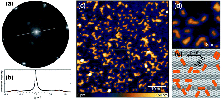
We initially performed spot-profile-analysis low-energy electron diffraction (SPA-LEED) measurements for 0.5 ML (monolayer) of pentacene deposited on Ir(111) at 320 K. The diffraction pattern, shown in Fig. 1(a) reveals broad diffraction spots and a (3 × 1) superperiodicity of 8.19 Å, compatible with side-by-side few-molecule ordering along the short molecular axis. The spot profile analysis, shown in Fig. 1(b) reveals that the average domain size is 25 Å in the short (× 3) periodicity direction, which is close to the size of 9 unit cells of the Ir(111) substrate. In the long axis direction, the spot width is 1.5 times larger, giving an average ordered domain size of 17 Å, almost compatible with a single molecular length.Scanning-tunneling microscopy (STM) measurements performed for the adsorbed pentacene molecules (see Fig. 1(c)) give a direct confirmation of the structure, with an almost random distribution of the molecules on the flat terraces of the Ir(111) surface. The analysis of the STM images acquired at higher resolution, reported in Fig. 1(d), clearly indicates that the molecular axis is aligned with the three main crystallographic directions of the substrate (see Fig. 1(e)).
Next, high-resolution X-ray photoelectron spectroscopy (HR-XPS) was employed in order to characterize the adsorbed pristine pentacene molecules. C 1s core level spectra have been initially acquired with increasing pentacene coverages, as reported in Fig. 2(a). It is interesting to note that the two-peak line shape (with the A and B components at a binding energy, BE, of about 284.55 and 283.85 eV) resembles that of pentacene in the gas phase,38 although the spectral weights are inverted. The spectra present a very similar line shape regardless of the pentacene amount, suggesting that increasing molecular coverage does not influence the adsorption site and that the interaction with defects, such as step edges of the Ir surface, which could act as nucleation centers of adsorption, is negligible even at lower coverages. This hypothesis is also confirmed by STM analysis that shows that steps are not playing a particular role in the RT pentacene adsorption process, with the molecules being homogeneously distributed on the surface. At coverages higher than 0.9 ML, shoulders start to appear in the C 1s spectrum and are more pronounced at higher BEs with respect to the two main peaks, indicating that a multilayer starts to form, thus confirming that the two-component spectra all belong to a sub-monolayer coverage range. The C 1s lineshape is considerably different with respect to the one reported for pentacene adsorption on Al(001), where a minimum between the two spectral components is not present, most probably due to the different adsorption configuration or interaction strength with the substrate.39 However it is clear that the lower binding energy component presents a strong asymmetry which is difficult to explain as due to enhanced electron–hole pair excitation probability for C species in specific configurations, resulting in a large Anderson coefficient. Instead we believe that the shoulder can be most probably interpreted as due to the emission from non-equivalent carbon atoms in the pentacene molecule displaying a chemical shift. C 1s measurements were performed at different photon energies, in order to assess the photoelectron diffraction effects on the relative intensities of the individual components in the C 1s spectrum (see Fig. 2(b)). There is an evident modulation, with the integrated intensity of the two fitted components ranging from 1.25 at 375 eV to 1.95 at 400 eV. Based on these results, the photon energy of 400 eV was chosen for subsequent experiments. This is a compromise between maximizing the photoemission cross-section and photoelectron kinetic energy, which results in reduced back-scattering effects.
In order to shed light on the chemical identity of the C atoms producing the two different components we have performed X-ray photoelectron diffraction (XPD) simulations. XPD is a technique that has proven very effective to determine the adsorption site of molecules on surfaces,40 to reveal the chemical identity of spectral features in core-level spectra,41 to unravel the atomic and structural configuration of 2D materials on metallic single-crystal surfaces42–44 and to investigate about the presence of corrugation or rotational crystalline domains in graphene,45,46. In this study we have divided the C atom population of a pentacene molecule into two families, those forming a bond with hydrogen and those at the centre of the molecules which are only C–C bonded. The overall photoelectron emission in the scanning mode (at different photon energies in the range 320–420 eV and normal emission) of the two families and their ratio have been calculated, as shown in Fig. 2(c). It is clear that the photoelectron diffraction effects are playing a major role in determining the intensities of the two components, with the ratio being quite different with respect to the ideal atomic ratio of 1.75, shown as a blue dotted horizontal line. In particular at 375 and 400 eV the ratio between the two curves is 1.1 and 1.9, respectively, i.e. values which are very close to the experimental results, reported as red dots in Fig. 2(c). This result suggests that the C atoms at the edge of the molecule are those producing the C 1s low BE component.
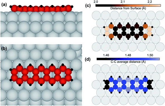
We furthermore performed density-functional theory (DFT) calculations for determining the preferential adsorption site of the pentacene molecules and consequently their adsorption geometry. Calculations were, at first, performed for isolated and for laterally non-interacting adsorbed molecules. As a starting point for the relaxation, several configurations with different translational and rotational symmetries were tested. The preferred configurations are those placed on high symmetry sites, namely top, hollow and bridge. The most stable was the bridge one, with the molecular axis aligned to a substrate crystallographic axis, and with the central aromatic ring centered on a substrate bridge position (see Fig. 3(a) and (b)). This adsorption configuration is clearly more stable, by 1.10 eV, than the one where the pentacene molecules, still with the molecular axis parallel to the main crystallographic direction, are placed with the central C ring in the hollow position. The adsorption site where the C ring is placed on top of an Ir substrate atom is much higher in energy, by 2.03 eV, and results in a deformation of the molecule, whose center rises considerably above the surface plane.
In the lowest energy configuration the C atoms in the two central rows form C bridges close to substrate top sites, while the lateral rows parallel to the main molecular axis of the pentacene molecules are situated near top sites. The C atoms at the extremes are slightly raised away from the surface, as illustrated in Fig. 3(c), giving a somewhat curved configuration. The bowl-shaped geometry that was found for coronene adsorbed on the same surface47 is translated to a U-shape in this uni-dimensional polyaromatic molecule. This effect is enhanced by the hydrogen atoms displaying an average height of 2.73 Å, 0.64 Å farther from the average height value of the C atoms. The C–C distance (see Fig. 3(d)) is always larger than the equivalent value for pentacene in isolated molecules,48 where the distances are smaller than 1.46 Å, and at the extremes even shorter than 1.43 Å. In our case, distances are stretched by at least 3%, implying that a large substrate-induced strain is present. This indicates considerable interaction with the metal substrate. A densely packed molecular layer was also simulated, with a larger (3 × 6) unit cell and determined by close packing in the long axis direction, so that 4 molecules would reside on the simulated slab. The results show that the lateral interaction between pentacene molecules is not negligible, with the adsorption energy/molecule being decreased by 0.52 eV. However, this is in agreement with the HR-XPS data, showing that the adsorption takes place even with a dense layer of molecules, and with the STM images, which show that pentacene islands are not formed. This is also in agreement with the SPA-LEED data, which indicate that, at most, a few molecules are found side-by-side, and almost none are found to interact at the ends, supporting the absence of large pentacene islands.
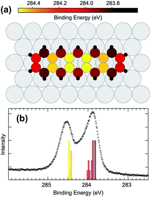
Comparing the calculated C 1s BE values (reported in Fig. 4(a) as colorscale) to gas phase data, it becomes evident that the carbon atoms situated at the molecular extremes, when adsorbed on Ir, have a much lower C 1s BE with respect to the gas phase (by 400 meV). The other atoms behave in a similar manner, with internal atoms at high BE, around 284.4 eV, and peripheral atoms at low BE, at 283.9 eV, resulting in a two peak spectral distribution. The DFT calculated BE distribution in the range 283.8–284 eV (Fig. 4(b)) clearly supports the interpretation of the larger asymmetry found in the lower binding energy component of the experimentally measured C 1s spectrum as due to inequivalent C atoms within the pentacene molecule.
Pentacene dehydrogenation/rehydrogenation
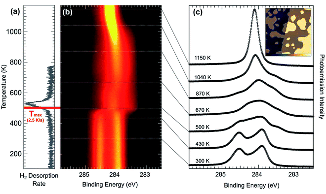
In a first step, temperature-programmed (TP)-XPS experiments49,50 have been performed in order to understand the thermal dissociation process for pentacene on Ir(111) (see Fig. 5(b)). The temperature evolution of the C 1s spectra shows that dissociation starts slightly below 500 K, at which the spectra rapidly settle to a shape that remains relatively unchanged up to 670 K, when it starts to gradually form a narrower and sharper component. Then, once 1000 K is reached, again the spectrum changes rapidly and the fingerprint of graphene formation is observed: a sharp peak at 284.1 eV emerges as the central component of the spectral distribution (top spectra in Fig. 5(c)). The small shoulder in the C 1s graphene spectrum observed at higher BE is commonly identified as defects in graphene, but is completely absent in this case, indicating that high quality graphene is formed using pentacene as a precursor on this surface. This is confirmed by the STM image (see inset in Fig. 5(c)), where it is possible to observe small sized islands of graphene. Regarding the initial spectral modification at about 480 K, the molecular hydrogen TPD spectra (see Fig. 5(a)) show a desorption peak between 480 K and 560 K, indicating that this first observed spectral change corresponds indeed to the dehydrogenation process: upon complete break-up of all C–H bonds the released hydrogen atoms diffuse on the surface until they form a hydrogen molecule which is known to desorb very rapidly at this temperature.47 The small discrepancy of the reaction temperature observed in TPD and TP-XPS is accounted for by the different annealing rate in the two experiments. According to the Redhead equation for desorption51 we expect that the maximum of the TPD signal is shifted by 27 K to lower temperature, thus giving a value in very good agreement with TP-XPS.In order to measure the C–H bond breaking energy we performed a series of fast-XPS measurements probing the evolution of the C 1s spectra at different temperatures and as a function of time. With the aim of obtaining more accurate information about the C 1s core level line-shape at different annealing temperatures, we performed a series of experiments after pentacene deposition at 300 K. Upon reaching selected temperatures, the annealing ramp was interrupted and the sample rapidly cooled to 300 K, where HR-XPS spectra have been acquired for intermediate species (see Fig. 5(c)). The spectra after annealing to 670, 870, and 1040 K have a quite similar spectral distribution to the DFT data from the C54 carbon cluster,47 indicating that very small graphene islands start to form already at such low temperatures, with the main graphene peak rising as the central component of the spectra compatible with carbon nanodomes of increasing size. As a consequence of increasing the temperature up to 1000 K, we observed the formation of a single-component C 1s peak, centered at BE = 284.15 eV, which is the fingerprint for a graphene layer on Ir(111).52–55
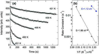
In order to obtain the value of the C–H dissociation barrier we monitored the evolution of the C 1s signal corresponding to the pristine molecules as a function of time at a fixed temperature, chosen between 450 and 500 K. To this end the sample was quickly brought to the selected temperature, by following a step-like temperature profile. Continuous data acquisition was then carried out until pristine molecules were no longer detectable in the spectra. Next, the intensity evolution of the component associated with the pristine molecules was determined fitting each spectrum as a function of time (see Fig. 6(a)). We noticed that the temporal evolution cannot be properly described by using just a single exponential decay, and a double-exponential has to be considered for fitting the data. This clearly suggests that two main barriers are needed to describe the whole pentacene rupture. Fig. 6(b) shows the Arrhenius plots for the two processes, where the reaction rate is plotted against inverse temperature in a log–lin plot. The measured values are 1.12 eV and 1.86 eV for the first and the second barrier, respectively. The first value is in very good agreement with the lowest energy barrier found using DFT for the removal of the first hydrogen atom from pentacene (see Fig. S1 in the ESI†). Depending on the C–H bond we found a barrier ranging from 1.11 eV for configuration 2, which corresponds to a C–H bond close to the molecular edge (Fig. S1†-central panel) to 1.95 eV for configuration 1, which corresponds to the C–H bond exactly at the edge of the molecule. For the removal of the second H atoms we calculated the barrier for configurations 1 and 3 (Fig. S1†-bottom panel), i.e. those atoms which are close to the first one. For configuration 3, which shows the lowest barrier (E3 = 1.12 eV), we have also found that the presence of the firstly removed H atoms in the three-fold site decreases the barrier by about 0.1 eV. This is hinting at some availability of H atoms diffusing on the surface and close to the molecule, which could play a role in the modification of the overall reaction behavior. Interestingly, the final state configuration for the first and second dissociation steps indicates that the molecular geometry is not strongly affected. This observation is confirmed by the STM experiments (shown in Fig. 2S†), in which pentacene molecules are imaged after surface annealing to 530 K, a temperature at which all the C–H bonds have broken. The overall unmodified contrast in the image, before and after annealing suggests that without hydrogen the C atoms of the molecules retained a conformation similar to the one before dissociation.
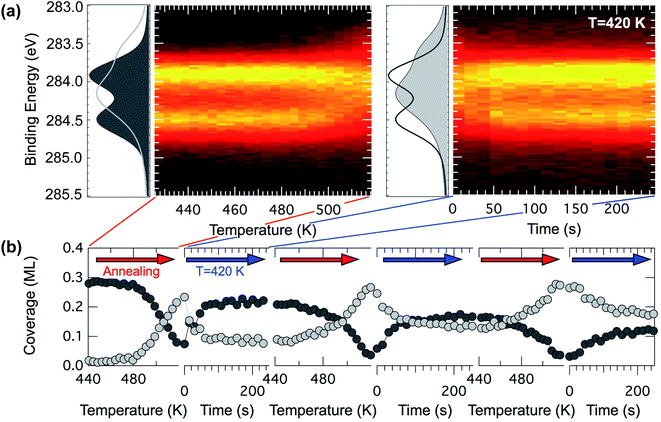
On the basis of this knowledge we investigated the evolution of a pentacene covered surface (0.6 ML) in a hydrogen atmosphere (P = 5 × 10⁻⁷ mbar) at increasing temperature. We revealed that if the annealing ramp is ended at 520 K and the sample rapidly quenched to 420 K, the C 1s spectra mostly return to the original lineshape (dark gray curve in Fig. 7(a)) after the expected change above 500 K (light gray curve in Fig. 7(a)). The temperature of 520 K has been chosen on the basis of the spectral distribution, which is compatible with the spectrum of the dehydrogenated molecules in the TP-XPS series. This process has been observed to be reproducible for a few cycles, even though every time the reforming of pentacene molecules is about 80% efficient (see dark gray markers in Fig. 7(b)), with spectra corresponding to pristine pentacene molecules showing a slightly shallower minimum in between the two main components. We interpret this as a complete rehydrogenation of a portion of the pentacene molecules.
There are possible explanations for the incomplete rehydrogenation observed. One possibility is that the molecules might sinter and start forming small patches of graphene. Sintering along the long edges is however unlikely, since the spectra reveal a shape compatible with carbon nanodomes only at higher temperatures, but they might still be forming dimers or longer n-mers, generating spaghetti-like structures as in the case of pentacene on Ni(111).56 A second explanation might be that, upon losing the hydrogen atoms, a small portion of the molecules could move slightly from their original and preferred adsorption site, due to lateral interactions. In this case the C 1s core level spectra might not change, since the interaction with the substrate could still be the leading factor in determining the spectral lineshape. However in this picture the free surface between the molecules would not be large enough for hydrogen dissociative adsorption and diffusion to favorable sites to occur. Hydrogen atoms necessary for the rehydrogenation would not be available close to the molecules, which could be a crucial requirement for rehydrogenation, since the surface residence time of atomic hydrogen on the hot Ir surface is very small, and the dissociative H2 adsorption process would have to happen very close to the molecules in order for the rehydrogenation reaction to take place.
Conclusion
Pentacene single layers have been characterized by a variety of spectroscopy-, diffraction- and microscopy-based experimental techniques in combination with DFT calculations. The adsorption geometry for pentacene on Ir(111) was found to be almost flat, displaying only a slightly U-shaped configuration, with the molecular axis being oriented along the substrate crystallographic axis, with the central aromatic ring adsorbed in a bridge position. The thermal dehydrogenation of pentacene on Ir(111) has been characterized by TP-XPS up to 1280 K, where the formation of graphene is observed. The dehydrogenation was found to happen between 450 and 550 K, as confirmed by TPD. The experiments reveal that the dehydrogenation process is compatible with a double reaction barrier. The first and lower barrier (1.12 eV) is in very good agreement with the results of DFT calculations (1.11 eV), while the second barrier (1.86 eV) which has to be overcome to reach the complete C–H dissociation represents the rate determining step of the overall process. Remarkably the pristine pentacene adlayer after dehydrogenation can be rehydrogenated by simply cooling the sample in a H2 atmosphere (P = 5 × 10⁻⁷ mbar). The reversible reaction we observed is therefore quite special, since the edge C atoms do not bind to Ir atoms so strongly due to the geometry of the adsorbed C22 nanocluster. This peculiarity can be exploited to shed light on how to engineer C-nanoclusters or to produce polyacenes, via on-surface synthesis, as shown for example in the case of nanoacene.24Our findings could be instrumental for the understanding of the fundamental properties of GNRs, that to date have been prevalently synthesized in a hydrogen capped form. GNRs may also have interesting higher electron/hole mobilities and better thermal transport when dehydrogenated, so this reaction also has interesting technological applications given the potential importance of thermal switching capabilities of nanoribbons. Finally, the process of hydrogenation/dehydrogenation of pentacene has important implication in heterogeneous catalysis57 and in astrophysics since the zigzag edges show strong infrared signatures which have been detected in astronomical spectra and could play, as for other polycyclic aromatic hydrocarbons, an important role in the formation of H2, the most abundant molecule of the universe.58
Authors' contributions
A. B. has conceived and designed the experiment. D. C., L. B., L. S., P. L., S. L. and A. B. took part in the acquisition of X-ray photoelectron spectra and diffraction data. D. C., E. S. and A. B. carried out the acquisition of low-energy electron diffraction data. D. C. analyzed the photoemission and low-energy electron diffraction data. E. S. carried out the STM data acquisition and analysis. L. B. carried out the X-ray photoelectron diffraction simulations. M. P. and D. A. carried out the DFT calculations. D. C. and A. B. wrote the manuscript. All the authors discussed extensively the results presented and reviewed the final version of the manuscript.Conflicts of interest
There are no conflicts to declare.Acknowledgements
We acknowledge financial support from the University of Trieste under the project METAMAT. We are grateful, for computational resources, to ARCHER UK National Supercomputing Service, United Kingdom (NE/M000990/1 and NE/R000425/1), the University College London (UCL) Research Computing, the MMM hub (EP/P020194/1) and Oak Ridge Leadership Computing Facility (DE-AC05-00OR22725). http://www.archer.ac.ukReferences
- I. Fernández, Chem. Sci., 2020, 11, 3769–3779 RSC.
- J. E. Anthony, Angew. Chem., Int. Ed., 2008, 47, 452–483 CrossRef CAS.
- J. E. Anthony, Chem. Rev., 2006, 106, 5028–5048 CrossRef CAS.
- A. R. Murphy and J. M. Frechet, Chem. Rev., 2007, 107, 1066–1096 CrossRef CAS.
- Y.-Y. Lin, D. Gundlach, S. Nelson and T. N. Jackson, IEEE Electron Device Lett., 1997, 18, 606–608 CAS.
- C. D. Dimitrakopoulos and P. R. Malenfant, Adv. Mater., 2002, 14, 99–117 CrossRef CAS.
- N. Karl, Synth. Met., 2003, 133, 649–657 CrossRef.
- Y. Yamashita, Sci. Technol. Adv. Mater., 2009, 10, 024313 CrossRef.
- G. Wang, Y. Luo and P. H. Beton, Appl. Phys. Lett., 2003, 83, 3108–3110 CrossRef CAS.
- L. Kyhl, R. Bisson, R. Balog, M. N. Groves, E. L. Kolsbjerg, A. M. Cassidy, J. H. Jørgensen, S. Halkjær, J. A. Miwa, A. G. Čabo, T. Angot, P. Hofmann, M. A. Arman, S. Urpelainen, P. Lacovig, L. Bignardi, H. Bluhm, J. Knudsen, B. Hammer and L. Hornekaer, ACS Nano, 2017, 12, 513–520 CrossRef.
- G. Wang, Chem. Phys. Lett., 2012, 533, 74–77 CrossRef CAS.
- K. Kusakabe and M. Maruyama, Phys. Rev. B, 2003, 67, 092406 CrossRef.
- P. Ruffieux, J. Cai, N. C. Plumb, L. Patthey, D. Prezzi, A. Ferretti, E. Molinari, X. Feng, K. Müllen, C. A. Pignedoli and R. Fasel, ACS Nano, 2012, 6, 6930–6935 CrossRef CAS.
- Y.-C. Chen, D. G. De Oteyza, Z. Pedramrazi, C. Chen, F. R. Fischer and M. F. Crommie, ACS Nano, 2013, 7, 6123–6128 CrossRef CAS.
- X. Zhang, O. V. Yazyev, J. Feng, L. Xie, C. Tao, Y.-C. Chen, L. Jiao, Z. Pedramrazi, A. Zettl, S. G. Louie, H. Dai and M. F. Crommie, ACS Nano, 2013, 7, 198–202 CrossRef CAS.
- P. Ruffieux, S. Wang, B. Yang, C. Sánchez-Sánchez, J. Liu, T. Dienel, L. Talirz, P. Shinde, C. A. Pignedoli, D. Passerone, T. Dumslaff, X. Feng, K. Müllen and R. Fasel, Nature, 2016, 531, 489 CrossRef CAS.
- M. Wang and C. M. Li, Nanoscale, 2011, 3, 2324–2328 RSC.
- Z. Wang, Q. Li, H. Zheng, H. Ren, H. Su, Q. Shi and J. Chen, Phys. Rev. B, 2007, 75, 113406 CrossRef.
- W. J. Evans, L. Hu and P. Keblinski, Appl. Phys. Lett., 2010, 96, 203112 CrossRef.
- L. E. Dinca, C. Fu, J. M. MacLeod, J. Lipton-Duffin, J. L. Brusso, C. E. Szakacs, D. Ma, D. F. Perepichka and F. Rosei, ACS Nano, 2013, 7, 1652–1657 CrossRef CAS.
- S. Haq, F. Hanke, J. Sharp, M. Persson, D. B. Amabilino and R. Raval, ACS Nano, 2014, 8, 8856–8870 CrossRef CAS.
- M. Zugermeier, M. Gruber, M. Schmid, B. P. Klein, L. Ruppenthal, P. Müller, R. Einholz, W. Hieringer, R. Berndt, H. F. Bettinger and J. M. Gottfried, Nanoscale, 2017, 9, 12461–12469 RSC.
- R. Zuzak, R. Dorel, M. Kolmer, M. Szymonski, S. Godlewski and A. M. Echavarren, Angew. Chem., Int. Ed., 2018, 57, 10500–10505 CrossRef CAS.
- R. Zuzak, R. Dorel, M. Krawiec, B. Such, M. Kolmer, M. Szymonski, A. M. Echavarren and S. Godlewski, ACS Nano, 2017, 11, 9321–9329 CrossRef CAS.
- J. Krüger, F. García, F. Eisenhut, D. Skidin, J. M. Alonso, E. Guitián, D. Pérez, G. Cuniberti, F. Moresco and D. Peña, Angew. Chem., Int. Ed., 2017, 56, 11945–11948 CrossRef.
- G. Galeotti, F. D. Marchi, T. Taerum, L. V. Besteiro, M. E. Garah, J. Lipton-Duffin, M. Ebrahimi, D. F. Perepichka and F. Rosei, Chem. Sci., 2019, 10, 5167–5175 RSC.
- A. L. Pinardi, J. I. Martínez, A. Jančařík, I. G. Stará, I. Starý, M. F. López, J. Méndez and J. Á. Martín-Gago, Chem. Commun., 2013, 50, 1555–1557 RSC.
- J. I. Urgel, S. Mishra, H. Hayashi, J. Wilhelm, C. A. Pignedoli, M. D. Giovannantonio, R. Widmer, M. Yamashita, N. Hieda, P. Ruffieux, H. Yamada and R. Fasel, Nat. Commun., 2019, 10, 861 CrossRef.
- J. Cai, P. Ruffieux, R. Jaafar, M. Bieri, T. Braun, S. Blankenburg, M. Muoth, A. P. Seitsonen, M. Saleh, X. Feng, K. Müllen and R. Fasel, Nature, 2010, 466, 470–473 CrossRef CAS.
- H. Zhang, H. Lin, K. Sun, L. Chen, Y. Zagranyarski, N. Aghdassi, S. Duhm, Q. Li, D. Zhong, Y. Li, K. Müllen, H. Fuchs and L. Chi, J. Am. Chem. Soc., 2015, 137, 4022–4025 CrossRef CAS.
- A. L. Pinardi, G. Otero-Irurueta, I. Palacio, J. I. Martinez, C. Sanchez-Sanchez, M. Tello, C. Rogero, A. Cossaro, A. Preobrajenski, B. Gómez-Lor, A. Jancarik, S. Irena, S. Ivo, L. Francisca, M. Javier and J. A. Martin-Gago, ACS Nano, 2013, 7, 3676–3684 CrossRef CAS.
- A. Narita, Z. Chen, Q. Chen and K. Müllen, Chem. Sci., 2019, 10, 964–975 RSC.
- A. Fairbrother, J.-R. Sanchez-Valencia, B. Lauber, I. Shorubalko, P. Ruffieux, T. Hintermann and R. Fasel, Nanoscale, 2017, 9, 2785–2792 RSC.
- Y. Ishii, H. Song, H. Kato, M. Takatori and S. Kawasaki, Nanoscale, 2012, 4, 6553 RSC.
- D. Lizzit, M. I. Trioni, L. Bignardi, P. Lacovig, S. Lizzit, R. Martinazzo and R. Larciprete, ACS Nano, 2019, 13, 1828–1838 CAS.
- F. Zaera, Langmuir, 1991, 7, 1998–1999 CrossRef CAS.
- P. Lacovig, M. Pozzo, D. Alfè, P. Vilmercati, A. Baraldi and S. Lizzit, Phys. Rev. Lett., 2009, 103, 166101 CrossRef.
- C. Baldacchini, C. Mariani and M. G. Betti, J. Chem. Phys., 2006, 124, 154702 CrossRef.
- A. Baby, G. Fratesi, S. R. Vaidya, L. L. Patera, C. Africh, L. Floreano and G. P. Brivio, J. Phys. Chem. C, 2015, 119, 3624–3633 CrossRef CAS.
- F. Bondino, G. Comelli, F. Esch, A. Locatelli, A. Baraldi, S. Lizzit, G. Paolucci and R. Rosei, Surf. Sci., 2000, 459, L467–L474 CrossRef CAS.
- S. Lizzit, K. Pohl, A. Baraldi, G. Comelli, V. Fritzsche, E. W. Plummer, R. Stumpf and P. Hofmann, Phys. Rev. Lett., 1998, 81, 3271–3274 CrossRef CAS.
- H. Bana, E. Travaglia, L. Bignardi, P. Lacovig, C. E. Sanders, M. Dendzik, M. Michiardi, M. Bianchi, D. Lizzit, F. Presel, D. D. Angelis, N. Apostol, P. K. Das, J. Fujii, I. Vobornik, R. Larciprete, A. Baraldi, P. Hofmann and S. Lizzit, 2D Mater., 2018, 5, 035012 CrossRef.
- L. Bignardi, D. Lizzit, H. Bana, E. Travaglia, P. Lacovig, C. E. Sanders, M. Dendzik, M. Michiardi, M. Bianchi, M. Ewert, L. Buß, J. Falta, J. I. Flege, A. Baraldi, R. Larciprete, P. Hofmann and S. Lizzit, Phys. Rev. Mater., 2019, 3, 014003 CrossRef CAS.
- F. Orlando, P. Lacovig, L. Omiciuolo, N. G. Apostol, R. Larciprete, A. Baraldi and S. Lizzit, ACS Nano, 2014, 8, 12063–12070 CrossRef CAS.
- L. Bignardi, P. Lacovig, M. M. Dalmiglio, F. Orlando, A. Ghafari, L. Petaccia, A. Baraldi, R. Larciprete and S. Lizzit, 2D Mater., 2017, 4, 025106 CrossRef.
- S. Ulstrup, P. Lacovig, F. Orlando, D. Lizzit, L. Bignardi, M. Dalmiglio, M. Bianchi, F. Mazzola, A. Baraldi, R. Larciprete, P. Hofmann and S. Lizzit, Surf. Sci., 2018, 678, 57–64 CrossRef CAS.
- D. Curcio, L. Omiciuolo, M. Pozzo, P. Lacovig, S. Lizzit, N. Jabeen, L. Petaccia, D. Alfè and A. Baraldi, J. Am. Chem. Soc., 2016, 138, 3395–3402 CrossRef CAS.
- R. Endres, C. Fong, L. Yang, G. Witte and C. Wöll, Comput. Mater. Sci., 2004, 29, 362–370 CrossRef CAS.
- A. Baraldi, G. Comelli, S. Lizzit, D. Cocco, G. Paolucci and R. Rosei, Surf. Sci., 1996, 367, L67–L72 CrossRef CAS.
- A. Baraldi, G. Comelli, S. Lizzit, M. Kiskinova and G. Paolucci, Surf. Sci. Rep., 2003, 49, 169–224 CrossRef CAS.
- P. Redhead, Vacuum, 1962, 12, 203–211 CrossRef CAS.
- S. Lizzit and A. Baraldi, Catal. Today, 2010, 154, 68–74 CrossRef CAS.
- S. Lizzit, G. Zampieri, L. Petaccia, R. Larciprete, P. Lacovig, E. D. L. Rienks, G. Bihlmayer, A. Baraldi and P. Hofmann, Nat. Phys., 2010, 6, 345–349 Search PubMed.
- F. Presel, N. Jabeen, M. Pozzo, D. Curcio, L. Omiciuolo, P. Lacovig, S. Lizzit, D. Alfè and A. Baraldi, Carbon, 2015, 93, 187–198 CrossRef CAS.
- F. Presel, H. Tetlow, L. Bignardi, P. Lacovig, C. A. Tache, S. Lizzit, L. Kantorovich and A. Baraldi, Nanoscale, 2018, 10, 7396–7406 RSC.
- L. Dinca, F. De Marchi, J. MacLeod, J. Lipton-Duffin, R. Gatti, D. Ma, D. Perepichka and F. Rosei, Nanoscale, 2015, 7, 3263–3269 RSC.
- Z.-J. Zhao, C.-C. Chiu and J. Gong, Chem. Sci., 2015, 6, 4403–4425 RSC.
- E. Rauls and L. Hornekær, Astrophys. J., 2008, 679, 531 CrossRef CAS.
Footnotes |
| † Electronic supplementary information (ESI) available: Experimental methods, XPD and DFT calculations details. See DOI: 10.1039/d0sc03734f |
| ‡ Present address: Department of Physics and Astronomy, Interdisciplinary Nanoscience Center (iNANO), Aarhus University, 8000 Aarhus C, Denmark. |
| This journal is © The Royal Society of Chemistry 2021 |

