DOI:
10.1039/D1RA07138F
(Paper)
RSC Adv., 2021,
11, 36636-36643
Nanoarchitectonics of p-type BiSbTe with improved figure of merit via introducing PbTe nanoparticles†
Received
24th September 2021
, Accepted 6th November 2021
First published on 12th November 2021
Abstract
Bi0.4Sb1.6Te3 (BST) is known to be a unique p-type commercial thermoelectric (TE) alloy used at room temperatures, but its figure of merit (ZT) is relatively low for wide industrial applications. To improve its ZT value is vitally important. Here, we show that the incorporation of 0.5 wt% PbTe nanoparticles into BST concurrently causes a large enhancement of power factor (PF) and a significant reduction of lattice thermal conductivity κL. The increase in PF mainly benefits from the optimization of carrier concentration, maintenance of high carrier mobility and constant rise in Seebeck coefficient. The decrease in κL can be attributed to the enhanced phonon scattering by the dispersed PbTe nanoparticles and the interfaces between PbTe and the BST matrix by using the Callaway model. Specifically, an ultralow κL of 0.26 W m−1 K−1 at 429 K is achieved for the composites incorporating 0.5 wt% PbTe nanoinclusions. Consequently, an excellent ZT = 1.6 at 482 K and a high average ZTave = 1.38 at 300–500 K are achieved, indicating that incorporation of PbTe in BST is an effective approach to improve its thermoelectric performance.
1. Introduction
Thermoelectric (TE) materials have attracted much attention as clean renewable sources because of their capability to harvest energy.1–3 The efficiency of TE materials is determined by the dimensionless figure of merit (ZT), defined as ZT = S2T/ρκ, where T, S, ρ and κ are the absolute temperature, Seebeck coefficient, electrical resistivity and thermal conductivity, respectively.4,5 In order to achieve high ZT values, one must maximize the power factor PF (= S2/ρ) and simultaneously minimize the thermal conductivity κ. However, S, ρ and κ are dependent on each other, and it is extremely difficult to simultaneously optimize these three TE parameters.
BiSbTe is the best known p-type TE material at room temperatures. Over the years, various strategies have been implemented to elevate the ZT values of BiSbTe alloys. Among them, optimizing the hole concentration p is the most effective way to improve the electrical transport and achieve high PF.6,7 In p-type BiSbTe crystal, when cations occupy the vacant anion sites, it creates antisite defects. The formation energy of antisite defects depends on polarity of the bonds between cations and anions. The hole concentration p can be increased by raising the Sb content in BiSbTe structure as it can reduce the formation energy of antisite defects. Previous studies have shown that Bi0.4Sb1.6Te3 (BST) possesses the optimal p (∼1019 cm−3) and the highest PF (∼45 μW cm−1 K−2) at room temperature.8–11 On the other hand, nanostructuring and nanocompositing in bulk materials have been widely employed to intensify the scattering of phonons in order to reduce κ.12–15 Compared to TE nanomaterials, nanocomposite TE materials are relatively easy to prepare and investigate. The introduction of nanoinclusions into bulk TE materials can simultaneously create a high density of phase boundaries to scatter phonons in order to greatly lower κ. However, in this case PF generally declines due to sharp reduction in carrier mobility μ. Therefore, whether one can introduce nanoinclusions into BST alloys that can not only reduce κ but also enhance PF is greatly challenging, because this will bring a large improvement of ZT.
In this work, BST alloys containing PbTe nanoparticles were fabricated, and their TE properties were investigated. PbTe is one of the most studied TE materials with a high ZT value of 1.8–2.2 at medium temperatures.16,17 Several previous reports have been reported about the TE properties of the composite with bismuth telluride and PbTe,18,19 but their ZT values are still relatively low for wide applications. In our experiment, PbTe nanoparticles were synthesized through hydrothermal procedure, which is different from the previously reported vacuum melting method.18,19 In this way, the obtained PbTe nanoparticles own the advantages of small granularity, uniform distribution and less reunion, which will effectively enhance phonon scattering and reduce the lattice thermal conductivity κL in the PbTe/BST nanocomposites. In addition, the asymmetric interface potentials between PbTe and BST will inhibit the transport of the thermally excited electrons to lower the bipolar effect, which will elevate S and reduce κ at elevated temperatures. Our experimental results show that the incorporation of 0.5 wt% of PbTe into BST indeed results in both enhanced PF and reduced κ. Specifically, an extremely low κL of 0.26 W m−1 K−1 at 429 K is reached, approaching the amorphous limit in the BiSbTe system, while maintaining a high PF. Consequently, a peak ZT of 1.6 at 482 K and a high average ZT (ZTave) of 1.38 at 300–500 K are achieved in the nanocomposites with 0.5 wt% PbTe, which are comparable to other reported start-of the-art TE materials in the same range of temperature.12,16,20–25 In what follows, the effect of the incorporation of PbTe nanoparticles on the TE properties of BST alloys will be analyzed in details.
2. Experimental
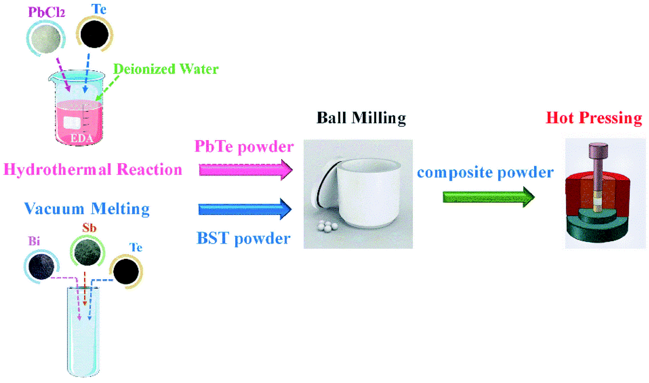
As shown in Fig. 1, elemental powders Bi (99.99%, Alfa Aesar), Sb (99.9%, Sigma Aldrich), and Te (99.99%, Alfa Aesar) granules were weighted according to the formula of Bi0.4Sb1.6Te3 doped with 3 wt% Te. The powder mixture was loaded into quartz ampoule sealed under vacuum at 10−3 Pa, and heated to 1073 K for 10 h. Then the ingot was grinded into powders. To synthesize the lead telluride with the nominal composition, 5 g NaBH4 and 15 g NaOH were put into a glass beaker filled with 600 mL deionized water; then 200 mL anhydrous ethylenediamine was added to the beaker. To make the reaction proceed homogeneously, the solution was stirred at room temperature with a magnetic stirrer. In the process, 50 mmol Te powder was added into the solution. Then, the solution was heated to 423 K on the oil bath. Subsequently, 50 mmol PbCl2 was added in the beaker; then, the solution was stirred at a speed of 1700 rpm and was kept at 423 K. After about 1 h, a large quantity of powders were precipitated. Then the precipitates were collected, filtered and washed respectively with anhydrous ethanol and distilled water until a pH value close to 7. The acquired powders were then dried in vacuum furnace at 353 K for 6 h. The nanometer-sized PbTe and BST powders were mixed in a planetary mill for 2 h with a certain weight ratios of 0.25![[thin space (1/6-em)]](https://www.rsc.org/images/entities/char_2009.gif) :99.75, 0.5:99.5, 1:99. Then the bulk nanocomposite samples were obtained by hot-pressing the blended powders under a pressure of 600 MPa in a vacuum at 673 K for 1 h.
:99.75, 0.5:99.5, 1:99. Then the bulk nanocomposite samples were obtained by hot-pressing the blended powders under a pressure of 600 MPa in a vacuum at 673 K for 1 h.
 |
| | Fig. 1 Schematic diagram of the hydrothermal reaction for PbTe powder, vacuum melting for BST samples, ball milling and hot pressing processes. | |
The phase structure of sample was studied by X-ray diffraction (XRD, Philips diffractometer, Cu Kα radiation) at room temperature. The fractograph of the composite χ(PbTe)/BST (here, we take χ = 0.5 wt% for instance) was observed by field emission scanning electron microscopy (FE-SEM, FEI Sirion 200). Moreover, transmission electron microscopy (TEM, Tecnai F30) was used to carry out the microstructure investigations. X-ray photoelectron spectroscopy (XPS, Thermo Kalpha) was used to perform element analysis of the composite sample. ρ and S were measured simultaneously by commercial equipment (ULVAC-RIKO: ZEM-3, Japan) under He atmosphere from 300 to 500 K. The thermal diffusivity, D, was measured using the laser flash method (Netzsch, LFA-457). Moreover, in consideration of the anisotropic characteristic of Bi2Te3-based alloys, D was measured along the direction perpendicular to the hot-pressing direction, ensuring that the thermal and electrical properties were measured in the same direction. The specific heat, Cp, was determined by a commercial instrument (Pyris Diamond DSC, PerkinElmer). The density, d, was measured by the Archimedes' method (using ethylalcohol as liquid medium, AR). The resulting total thermal conductivity κ was calculated from the measured thermal diffusivity D, density d and specific heat Cp from the relationship κ = DdCp. The Hall coefficient was measured at 300 K using the physical property measurement system (PPMS), and the hole concentration p and mobility μ were calculated using Hall coefficient and electrical resistivity ρ. The accuracies in ρ, S, and κ are around ±2, ±3, and ±5%, respectively. The combined uncertainty of ZT is around ±12%.
3. Results and discussion
Fig. 2(a) shows XRD patterns of BST, PbTe and composite samples χ(PbTe)/BST (χ = 0.25, 0.5 and 1.0 wt%). The main diffraction peaks correspond well to the standard JCPDS cards (BST: no. 72-1836, PbTe: no. 002-1132). Apart from the main diffraction peaks of BST, an additional small peak (200) from the PbTe phase appears in the XRD patterns of the composite samples (χ > 0), and the intensity of the peak increases with the increasing PbTe content, which indicates that no obvious impurity phase forms other than the two constituent phases (BST and PbTe). In addition, the average grain size for PbTe nanoparticles is ∼30 nm that is determined from peak broadening of the XRD pattern for PbTe based on the Scherrer formula.
 |
| | Fig. 2 (a) XRD patterns for BST, PbTe and composite samples χ(PbTe)/BST (χ = 0.25, 0.5 and 1.0 wt%); (b) FE-SEM micrograph of fracture surface of PbTe/BST bulk composite sample; (c) HRSEM image of the selected rectangle area in (b); (d) TEM bright-field image of PbTe/BST, showing the BST matrix, the incorporated PbTe nanoparticles and typical phase boundaries between them. | |
The FESEM fractograph of the bulk PbTe/BST composite sample is shown in Fig. 2(b). The plate-shaped grains can be observed, which reveal the typical structure of BiSbTe-based compounds. By further careful inspection from Fig. 2(b), one can find some small particles with sizes of ∼20 to ∼80 nm distributed in the BST matrix (Fig. 2(c)). Further analysis with energy dispersive X-ray spectroscopy (EDX) indicates that the composites contain chemical element Pb and Te (Fig. S1†), verifying that the small particles are actually PbTe grains. The TEM image of PbTe/BST composite sample is shown in Fig. 2(d), from which one can see the PbTe nanoparticles, BST matrix and typical phase boundaries between them (as shown by the white dash line). Furthermore, due to the difference of the band gaps of PbTe (Eg = 0.32 eV) and BST (Eg = 0.17 eV), p–p type interface potentials will form at the heterojunction interfaces to guarantee the equal chemical potentials on both sides,18,26,27 as shown in Fig. S2.† In order to further examine chemical elements for the composite sample, XPS test was employed, and the overall spectrum is shown in Fig. 3. Fig. 3(a) discloses that the sample is composed of bismuth, tellurium, antimony and lead. Fig. 3(b)–(e) show the peaks corresponding to the bonding energies of Bi4f, Sb3d, Te3d and Pb4f, respectively. The XPS results clearly reveal that the composite sample contains two compounds: BST and PbTe.
 |
| | Fig. 3 XPS spectrum of PbTe/BST composite sample (a) survey spectrum; (b) Bi4f; (c) Sb3d; (d) Te3d; (e) Pb4f. | |
The electrical resistivity ρ as a function of temperature of χ(PbTe)/BST (χ = 0, 0.25, 0.5 and 1.0 wt%) is shown in Fig. 4(a). One can see that ρ for all the samples increases with increasing temperature, exhibiting a degenerate semiconductor behavior. On the other hand, ρ decreases with increasing content of PbTe. For example, ρ at 300 K decreases from 0.746 to 0.647, 0.448 and 0.381 Ω m, as χ increases from 0 to 0.25, 0.5 and 1.0 wt%, respectively. As shown in Fig. 4(b), the positive values of S for the composite samples (χ > 0) means that the major carriers in all the samples are holes. S decreases obviously with increasing content of PbTe. An interesting phenomenon, which can also be found in our previous work,18,26,27 is that the temperature at which S reach a maximum shifts to higher temperature as χ increases from 0 to 0.25, 0.5 and 1 wt%, and there is nearly no decline of S for the sample with χ = 0.5 and 1 wt%. The decline of S at high temperatures is due to the thermal excitation of electrons; however, the incorporation of PbTe nanoparticles can effectively inhibit the transport of these electrons by the interface potentials, and the more the PbTe content, the stronger this inhibition effect. In addition, the band gap Eg of the BST can be roughly calculated to be 0.17 eV by using the Goldsmid–Sharp relationship Eg = 2eSmaxTmax, where Smax is the peak value of S and Tmax is the corresponding temperature.28
 |
| | Fig. 4 Temperature dependences of (a) electrical resistivity ρ, (b) Seebeck coefficient S and (d) power factor PF for composite samples χ(PbTe)/BST (χ = 0, 0.25, 0.5 and 1.0 wt%). (c) Varieties of hole concentration p and mobility μ with PbTe content χ for composite samples χ(PbTe)/BST (χ = 0, 0.25, 0.5 and 1.0 wt%) at 300 K. | |
In order to understand the behavior of ρ and S, the hole concentration p was measured at room temperature. As shown in Fig. 4(c), p increases from 3.03 × 10¹⁹ to 6.79 × 1019 cm−3, as χ increases from 0 to 1 wt%. Meanwhile, the hole mobility μ decreases from 290.9 to 241.5 cm2 V−1 s−1 just with a small range according to the relationship ρ = 1/(peμ). This could be ascribed to that the lattice of PbTe with face-centered cubic structure can partly matching well with BST with dense hexagonal structure, which will weaken the carrier scattering to a certain extent. Furthermore, S of a degenerate semiconductor can be expressed by Mott formula:29
| |
 | (1) |
Formula (1) indicates that S decreases with increasing p, which can be applied to explain qualitatively why S decreases with increasing PbTe nanoinclusions as shown in Fig. 4(b).
Fig. 4(d) shows PF of χ(PbTe)/BST (χ = 0, 0.25, 0.5 and 1.0 wt%) as functions of temperature. One can see that PF of the BST matrix decreases fast with increasing temperature, while PF of the composite samples (χ > 0) shows a relative slow descent speed. PF of the incorporated samples enhances obviously especially at elevated temperatures. Thereinto, PF of the sample with χ = 0.5 wt% is larger than that of the BST matrix at the whole temperature range investigated here. For instance, PF of the sample with χ = 0.5 wt% is 33.8 μW (cm−1 K−2)−1 at 482 K, which is ∼33% larger than that of the BST matrix (25.5 μW (cm−1 K−2)−1).
The total thermal conductivity κ for all the samples is given in Fig. 5(a) as a function of temperature. One can see that κ for the BST matrix first decreases and then slightly increases with the elevation of temperature due to the bipolar effect. In comparison, κ for the composite samples (χ > 0) decreases with increasing temperature in the whole temperature range investigated, leading to a substantial decline in κ for the samples with χ = 0.25 and 0.5 wt% especially at high temperatures. For instance, as to the sample with χ = 0.5 wt%, κ decreases from 1.10 to 0.99 μW (cm−1 K−2)−1 at 482 K (a ∼10% decline). The total thermal conductivity κ can be expressed as κ = κL + κC + κb, where κC, κL and κb are the carrier thermal conductivity, lattice thermal conductivity, and thermal conductivity from the bipolar effect, respectively.30 Among them, κC can be estimated by the Wiedemann–Franz relation (κC = LT/ρ) as shown in Fig. 5(b), in which the Lorenz number L is estimated using formula (2) and (3) with the assumption of transport dominated by acoustic scattering and a single parabolic band:31
| |
 | (2) |
| |
 | (3) |
where
ξF is the reduced Fermi level
Ef/(
kBT). The obtained values of
L are 1.46–1.59 × 10
−8 V
2 K
−2, as listed in Table S1.
† Subsequently,
κL +
κb can be obtained from
κ −
LT/
ρ, as shown in
Fig. 5(c). It can be seen that
κL +
κb for the BST matrix decreases first as the temperature increases from 300 to 450 K; then, it increases as the temperature increases to 500 K due to a strong bipolar effect. By contrast,
κL +
κb for the composite samples (
χ > 0) shows a slight increase as the temperature increases from 450 to 500 K due to a reduced bipolar effect, which can be ascribed to the inhibition of the transport of thermally excited electrons by the interface potentials between PbTe nanoinclusions and BST matrix.
18,26,27 Moreover,
κL +
κb for the composite samples (
χ > 0) are reduced substantially as compared to that of the BST matrix. Specifically, a lower
κL = 0.26 W m
−1 K
−1 at 429 K is reached for the sample with
χ = 0.5 wt%, which is smaller than these of the reported state-of-the-art p-type BiSbTe-based alloys.
12,20–23 In order to clarify why the composite samples (
χ > 0) have significantly reduced
κL, the Debye–Callaway model was adopted in which
κL is expressed as:
32| |
 | (4) |
where
θD is the Debye temperature,
v is the average sound velocity,
τT is the total phonon relaxation time, and
z is the reduced phonon frequency. In our composite samples (
χ > 0), the dominant phonon-scattering mechanisms include scattering processes from point defects, incorporated PbTe nanoparticles, phonon–phonon Umklapp-scattering, and interfaces (grain/phase boundaries). Thus, total phonon relaxation time
τT can be expressed as the following relation:
32| |
 | (5) |
where
τPD,
τNP,
τU,
τE and
τIF are the relaxation times corresponding to scattering from the point defects, incorporated PbTe nanoparticles, phonon–phonon Umklapp-process, electron–phonon interaction and interfaces (between PbTe nanophase and BST matrix), respectively. In the Rayleigh scattering regime, the scattering cross section
φ has the relation
φ ∼
b6ω4 (or ∼
b6/
λ4), where
b is the size of the scatters and
ω (
λ) is the phonon frequency (wavelength). In the BST matrix, point defects, such as impurities and alloy elements, are the domain point defects that have the size of
b ∼0.1 nm, indicating that high-frequency (short-wavelength) phonons are scattered much more strongly than mid- and low-frequency (long-wavelength) phonons. Consequently, the mid- and low-frequency phonons are the main contributors to
κL in BST. As the incorporated PbTe nanoparticles have sizes of ∼20 to ∼80 nm with mean value of ∼30 nm, the mid- and low-frequency phonons will be strongly scattered by the embedded PbTe nanoinclusions, leading to a sharp reduction of
κL. Therefore, combing phonon scattering of both conventional point defects and embedded PbTe nanoparticles together because of their Rayleigh scattering character, formula
(5) can be rewritten as
32,33| | |
τT−1 = Aω4 + Bω2Texp(−θD/3T) + Cω2 + υ/l
| (6) |
where
l is the mean spatial distance among the PbTe nanoparticles in the BST matrix, and the term
v/
l represents the scattering from the interfaces (IF).
A,
B and
C are the pre-factors for the scattering from point defects (including embedded PbTe nanoparticles) (PD), Umklapp process (
U) and the electron–phonon interaction (
E), respectively. To calculate quantitatively
κL through formula
(4), the literature values of Debye temperature
θD = 94 K for BST and average sound velocity
v = 2147 m s
−1 were used.
34 By substituting formula
(6) for
τT in formula
(4) and through fitting the experimental
κL to formula
(4), one can obtain calculated
κL (solid orange line in
Fig. 5(c)) and magnitudes for parameters
A and
B for the BST matrix (Table S2
†). It can be seen that the calculated
κL is fitting well with the experimental data of the BST matrix in the temperature range of 300–450 K. For the composite samples (
χ > 0), only considering the additional scattering from the interfaces (IF), the calculated
κL will decrease to the position of the solid purple line as shown in
Fig. 5(c), manifested as the addition of
v/
l (
l = 126 nm as shown in Table S2
†) in formula
(6). Moreover, further considering the enhancement of phonon scattering by the PbTe nanoparticles (NP),
κL will decrease to the position of the wine line (being manifested as the rise of
A from 0.69 to 1.41 × 10
−40 s
3 as shown in Table S2
†), which is fitting well with the experimental data for the composite samples (
χ > 0) as shown in
Fig. 5(c). Consequently, the introduction of PbTe nanoparticles leads to a large reduction of
κL for the composite samples.
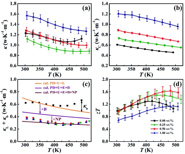 |
| | Fig. 5 Temperature dependences of (a) total thermal conductivity κ, (b) carrier thermal conductivity κC, (c) lattice thermal conductivity plus thermal conductivity from the bipolar effect κL + κb, and (d) ZT values for composite samples χ(PbTe)/BST (χ = 0, 0.25, 0.5 and 1.0 wt%). | |
Fig. 5(d) shows ZT for all the samples. Although the temperature behavior of ZT for all samples is similar: it increases with increasing temperature, and after reaching a maximum value ZT decreases with further increasing temperature, the peak temperatures (at which ZT gets a maximum value) for ZT of the composite samples (χ > 0) are larger than that of the BST matrix. Specially, ZT of the sample with χ = 0.5 wt% is larger than that of the BST matrix in almost the whole temperature range, and reaches a maximum value of ZT = 1.6 at 482 K, which is ∼25% larger than that of the BST matrix (ZTmax = 1.3 at 420 K). Moreover, the sample with χ = 0.5 wt% exhibits the highest average ZTave of 1.38 in the temperature range from 300 to 500 K, with the average ZT4
| |
 | (7) |
where
Th and
Tc are the hot side temperature and the cold side temperature, respectively. Both the
ZTmax and
ZTave values of the composite sample with
χ = 0.5 wt% are comparable to other reported state-of-the-art p-type BiSbTe-based alloys as well as typical TE materials,
12,16,20–25 as shown in
Table 1.
Table 1 ZTmax and ZTave values at 300–500 K of BST matrix, (0.5 wt% PbTe)/BST composite sample and other reported state-of-the-art p-type BiSbTe-based alloys as well as typical TE materials
| TE materials |
ZTmax |
ZTave |
Ref. |
| BiSbTe (ball milled nano-alloys) |
1.4 |
1.3 |
12 |
| CuGaTe2/BiSbTe |
1.53 |
1.36 |
20 |
| Bi0.5Sb1.495Cu0.005Te3 |
1.4 |
1.2 |
21 |
| ZnTe/BiSbTe |
1.4 |
1.2 |
22 |
| Fe3O4/BiSbTe |
1.5 |
1.25 |
23 |
| α-MgAgSb |
1.4 |
1.2 |
24 |
| PbTe |
0.78 |
0.37 |
16 |
| SnSe |
1.5 |
1.12 |
25 |
| BST matrix |
1.3 |
1.19 |
This work |
| PbTe/BST |
1.6 |
1.38 |
This work |
4. Conclusions
In summary, the incorporation of small content (0.5 wt%) of PbTe nanoparticles into BST matrix can lead to excellent TE performance resulting from concurrent increase in PF and decrease in κL. The increase in PF is mainly benefited from the optimization of p, maintenance of μ and constant rise in S due to inhibition of the transport of thermally excited electrons by the interface potentials; while by using the Callaway model we demonstrate that the ultralow κL of 0.26 W m−1 K−1 at 429 K for χ(PbTe)/BST (χ = 0.5 wt%) can be attributed to the enhanced phonon scattering by dispersed PbTe nanoparticles and the interfaces between the PbTe and BST matrix. As a result, a highest ZTmax of 1.6 (at 482 K) and an average ZTave of 1.38 (at 300–500 K) are achieved in the composite system with 0.5 wt% of PbTe. Present study demonstrates that the thermoelectric performance of BST can be effectively improved by incorporating proper amount of PbTe nanophase.
Author contributions
Yuanyue Li: conceptualization, data curation, funding acquisition, writing-original draft. Mengna Ren: formal analysis, software, visualization, investigation. Zhongsen Sun: resources, methodology, writing-review & editing. Zhao Yao: project administration, supervision, validation, writing-review & editing.
Conflicts of interest
There are no conflicts to declare.
Acknowledgements
Financial support from China Postdoctoral Science Foundation (No. 2017M612193), Natural Science Foundation of Shandong Province (No. ZR2018BEM017) and Qingdao Postdoctoral Applied Research Project Foundation is gratefully acknowledged.
References
- C. Yu and K. T. Chau, Energy Convers. Manage., 2009, 50, 1506–1512 CrossRef CAS
 .
. - L. E. Bell, Science, 2008, 321, 1457–1461 CrossRef CAS PubMed .
- T. Fujigaya, Bull. Chem. Soc. Jpn., 2019, 92, 400–408 CrossRef CAS .
- D. M. Rowe, Thermoelectrics handbook: macro to nano, CRC Press, 2005 Search PubMed .
- W. D. Liu, L. Yang, Z. G. Chen and J. Zou, Adv. Mater., 2020, 32, 1905703 CrossRef CAS PubMed .
- L. Yang, Z. G. Chen, M. S. Dargusch and J. Zou, Adv. Energy Mater., 2018, 8, 1701797 CrossRef .
- C. Gayner and Y. Amouyal, Adv. Funct. Mater., 2020, 30, 1901789 CrossRef CAS .
- D. Li, R. R. Sun and X. Y. Qin, Intermetallics, 2011, 19, 2002–2005 CrossRef CAS .
- ö. C. Yelgel and G. P. Srivastava, J. Appl. Phys., 2013, 113, 073709 CrossRef .
- S. I. Kim, K. H. Lee, H. A. Mun, H. S. Kim, S. W. Hwang, J. W. Roh, D. J. Yang, W. H. Shin, X. S. Li, Y. H. Lee, G. J. Snyder and S. W. Kim, Science, 2015, 348, 109–114 CrossRef CAS PubMed .
- J. Pei, B. W. Cai, H. L. Zhuang and J. F. Li, Natl. Sci. Rev., 2020, 7, 1856–1858 CrossRef .
- B. Poudel, Q. Hao, Y. Ma, Y. C. Lan, A. Minnich, B. Yu, X. Yan, D. Z. Wang, A. Muto, D. Vashaee, X. Y. Chen, J. M. Liu, M. S. Dresselhaus, G. Chen and Z. F. Ren, Science, 2008, 320, 634–638 CrossRef CAS .
- S. F. Fan, J. N. Zhao, J. Guo, Q. Y. Yan, J. Ma and H. H. Hng, Appl. Phys. Lett., 2010, 96, 182104 CrossRef .
- J. H. Li, Q. Tan, J. F. Li, D. W. Liu, F. Li, Z. Y. Li, M. M. Zou and K. Wang, Adv. Funct. Mater., 2013, 23, 4317–4323 CrossRef CAS .
- Y. C. Dou, X. Y. Qin, D. Li, L. L. Li, T. H. Zou and Q. Q. Wang, J. Appl. Phys., 2013, 114, 044906 CrossRef .
- K. Biswas, J. H. He, I. D. Blum, C. I. Wu, T. P. Hogan, D. N. Seidman, V. P. Dravid and M. G. Kanatzidis, Nature, 2012, 489, 414–418 CrossRef CAS PubMed .
- G. J. Tan, F. Y. Shi, S. Q. Hao, L. D. Zhao, H. Chi, X. M. Zhang, C. Uher, C. Wolverton, V. P. Dravid and M. G. Kanatzidis, Nat. Commun., 2016, 7, 12167 CrossRef CAS .
- S. J. Liang, J. T. Xu, H. X. Wang, X. J. Tan, G. Q. Liu, H. Z. Shao, B. Yu, S. Yue and J. Jiang, J. Mater. Sci.: Mater. Electron., 2018, 29, 7701–7706 CrossRef CAS .
- B. Xu, M. T. Agne, T. L. Feng, T. C. Chasapis, X. L. Ruan, Y. L. Zhou, H. M. Zheng, J. H. Bahk, M. G. Kanatzidis, G. J. Snyder and Y. Wu, Adv. Mater., 2017, 29, 1605140 CrossRef PubMed .
- Y. Y. Li, X. C. Wang, G. X. Liu, B. C. Shin and F. K. Shan, Scr. Mater., 2019, 172, 88–92 CrossRef CAS .
- F. Hao, P. F. Qiu, Y. S. Tang, S. Q. Bai, T. Xing, H. S. Chu, Q. H. Zhang, P. Lu, T. S. Zhang, D. D. Ren, J. K. Chen, X. Shi and L. D. Chen, Energy Environ. Sci., 2016, 9, 3120–3127 RSC .
- R. G. Deng, X. L. Su, S. Q. Hao, Z. Zheng, M. Zhang, H. Y. Xie, W. Liu, Y. G. Yan, C. Wolverton, C. Uher, M. G. Kanatzidis and X. F. Tang, Energy Environ. Sci., 2018, 11, 1520–1535 RSC .
- C. C. Li, S. F. Ma, P. Wei, W. T. Zhu, X. L. Nie, X. H. Sang, Z. G. Sun, Q. J. Zhang and W. Y. Zhao, Energy Environ. Sci., 2020, 13, 535–544 RSC .
- D. D. Li, H. Z. Zhao, S. M. Li, B. P. Wei, J. Shuai, C. L. Shi, X. K. Xi, P. J. Sun, S. Meng, L. Gu, Z. F. Ren and X. L. Chen, Adv. Funct. Mater., 2015, 25, 6478–6488 CrossRef CAS .
- L. D. Zhao, G. J. Tan, S. Q. Hao, J. Q. He, Y. L. Pei, H. Chi, H. Wang, S. K. Gong, H. B. Xu, V. P. Dravid, C. Uher and G. J. Snyder, Science, 2016, 351, 141–144 CrossRef CAS PubMed .
- Y. Y. Li, D. Li, X. Y. Qin, X. H. Yang, Y. F. Liu, J. Zhang, Y. C. Dou, C. J. Song and H. X. Xin, J. Mater. Chem. C, 2015, 3, 7045–7052 RSC .
- Y. Y. Li, X. Y. Qin, D. Li, J. Zhang, C. Li, Y. F. Liu, C. J. Song, H. X. Xin and H. F. Guo, Appl. Phys. Lett., 2016, 108, 062104 CrossRef .
- Z. M. Gibbs, H. S. Kim, H. Wang and G. J. Snyder, Appl. Phys. Lett., 2015, 106, 022112 CrossRef .
- T. H. Zou, X. Y. Qin, D. Li, G. L. Sun, Y. C. Dou, Q. Q. Wang, B. J. Ren, J. Zhang, H. X. Xin and Y. Y. Li, Appl. Phys. Lett., 2014, 104, 013904 CrossRef .
- S. K. Li, X. R. Liu, Y. D. Liu, F. S. Liu, J. Luo and F. Pan, Nano Energy, 2017, 39, 297–305 CrossRef CAS .
- E. S. Toberer, P. Rauwel, S. Gariel, J. Taftø and G. J. Snyder, J. Mater. Chem., 2010, 20, 9877–9885 RSC .
- J. Callaway, Phys. Rev., 1959, 113, 1046–1051 CrossRef CAS .
- W. Kim, J. Zide, A. Gossard, D. Klenov, S. Stemmer, A. Shakouri and A. Majumdar, Phys. Rev. Lett., 2006, 96, 045901 CrossRef PubMed .
- H. S. Kim, S. I. Kim, K. H. Lee, S. W. Kim and G. J. Snyder, Phys. Status Solidi B, 2017, 254, 1600103 CrossRef .
Footnote |
| † Electronic supplementary information (ESI) available. See DOI: 10.1039/d1ra07138f |
|
| This journal is © The Royal Society of Chemistry 2021 |
Click here to see how this site uses Cookies. View our privacy policy here. 
 Open Access Article
 This Open Access Article is licensed under a Creative Commons Attribution-Non Commercial 3.0 Unported Licence
 *
*