
 Open Access Article
 This Open Access Article is licensed under a Creative Commons Attribution-Non Commercial 3.0 Unported Licence
Estimation of rolling work of adhesion at the nanoscale with soft probing using optical tweezers†
Muruga Lokesha,
Rahul Vaippullya,
Gokul Nalupurackala,
Srestha Roya,
Vidya P. Bhallamudia,
Anil Prabhakarb and
Basudev Roy *a
*a
aDepartment of Physics, Indian Institute of Technology Madras, Chennai, 600036, India. E-mail: basudev@iitm.ac.in
bDepartment of Electrical Engineering, Indian Institute of Technology Madras, Chennai, 600036, India
First published on 26th October 2021
Abstract
Conventionally, the work of adhesion at the nanoscale is estimated using an atomic force microscope with a tip of the size of 10 nm. It is pressed into a surface with nano-Newton forces and then retracted to ascertain when the tip breaks away from the surface. Thus this ensures “hard probing” of a surface. However there can be another configuration where the particle is barely placed into the surface when the work of adhesion attaches the particle to the surface and this can be called “soft probing”. In this configuration, if a birefringent particle is confined in linearly polarized optical tweezers, and then the surface is moved in the direction tangential to the plane, a rolling motion can be induced. Study of this rolling motion can also show the work of adhesion. We use this configuration to find the rolling work of adhesion of a 3 μm diameter birefringent particle on a glass surface. We go on to study the effects of changing the surface to a hydrophobic slippery surface like polydimethyl siloxane (PDMS). Then we go on to show that even 500 nm diameter diamonds bearing nitrogen vacancy (NV) centers which are birefringent due to the stresses on the crystal could also be trapped and rolled to generate pitch (out-of-plane rotation) motion with 50 nm contact diameters. We find that this mode of soft probing yields a work of adhesion of about 1 mJ m−2 while the conventional nanoscale probing with atomic force microscopes (AFM) yields about 50 mJ m−2.
During the acute inflammatory response in the body, leukocytes roll on the endothelial cells lining the blood vessel wall toward the site of inflammation.1 The primary mechanism of rolling is due to adhesion at the wall while the shear flow due to the blood induces motion. This dynamic process involves rapid adhesion bond formation2,3 at the leading edge of leukocyte-endothelial contact and breaking at the trailing edge. There have been many studies on this adhesion system in the past two decades, highlighting the importance of cell rolling in the inflammatory response and cancer metastasis.4–9 Moreover, rolling adhesion was shown to be a promising mechanism to sort cells based on their receptor expressions.10 In all these studies, however, the exact rotation angle of the cell could not be directly visualised.
The work of adhesion at the nanoscale is often estimated by taking a very sharp atomic force microscope (AFM) tip (of the order of 10 nm) and then pressing it against a surface.11 Then the tip is gradually retracted and the force required to pull it away from the surface12,13 is recorded as the force of adhesion. While this provides insight into the nanoscale forces, it does require an initial hard pressing into the surface, which can hence be called “hard probing”. This gives a work of adhesion of the order of 50 mJ m−2.11 However, the work of adhesion during the rolling events mentioned in the previous paragraph have an entirely different origin as the probing required there is with much smaller forces,14 of the order of 10 pN. This can be called “soft probing”.15 In order to estimate this, we need to place a spherical particle gently onto the surface and then induce rolling motion to find the precise angles the particle rotated by. It can provide information about the rolling work of adhesion. As the contact area reduces to less than 100 nm diameter, we now approach the nanoscale.
In this manuscript, we use a single 3 μm diameter birefringent particle which is optically trapped on the surface of the sample chamber and then move the surface to generate rolling motion of the particle. The birefringence axis of the particle is initially aligned with the polarization of the trapping light, such that as soon as it rotates, there is now a restoring torque. When the torque due to adhesion becomes smaller than the restoring torque due to the polarization of light, the particle ceases to roll and slips out of the surface. We use this threshold torque value to estimate the rolling work of adhesion. We then go on to use a hydrophobic surface and also a smaller birefringent probe, a 500 nm diameter diamond particle, to estimate the work of adhesion due to rolling motion and find it to be of the order of 1 mJ m−2, much smaller than that found for the AFM tips. This mode of soft probing of the rolling motion has so far never been addressed due to the inability to detect rotational motion of spherical particles at these length scales.
According to the airlines nomenclature, among the three degrees of rotational freedom of a rigid body, the in-plane rotational motion can be called the yaw16,17 while the first out of plane rotational motion can be called pitch rotation. This pitch mode of rotational motion for a spherical rigid body has been sparsely explored till recently in the optical tweezers community. One of the first attempts was to use the convection currents in the neighborhood of the particle.18 Another method is to use 2 trapping beams with controllable foci in irregular shaped19 and even birefringent spherical particles. The present work shows a third and controllable way of generating pitch rotation while trapped in a single beam.
1 Theory
We optically trap a birefringent particle of about 3 μm diameter and place it on top of the glass surface of a sample chamber and then move the stage as shown in the Fig. 1. This ensures that due to the force of adhesion at the overlapping region, the particle actually rolls on the surface. | ||
| Fig. 1 This cartoon shows how a spherical particle confined at the center by an optical trap, rolls on a surface which has been moved parallel to the surface. | ||
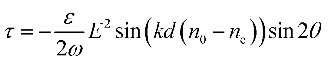
The torque (τ) due to such an optically confined particle by an elliptically polarized light16 is given as
 | (1) |
For a particle trapped in linearly polarized light, the ϕ = 0, so that the final torque is then
 | (2) |
Thus the Langevin equation then becomes
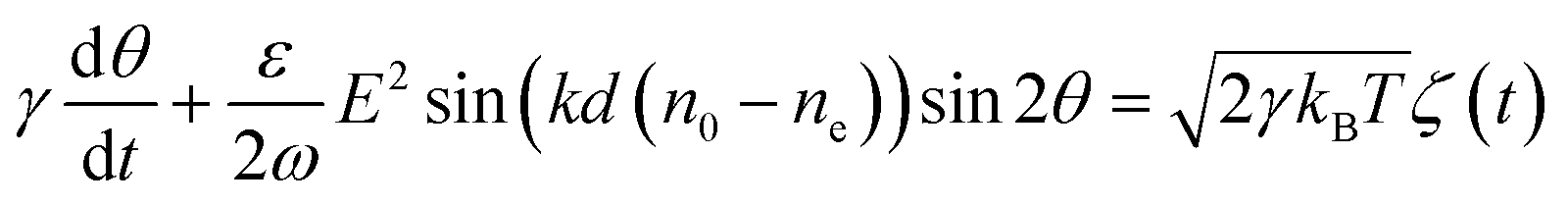 | (3) |
![[thin space (1/6-em)]](https://www.rsc.org/images/entities/char_2009.gif) 2θ is approximately 2θ, such that eqn (3) now becomes,
2θ is approximately 2θ, such that eqn (3) now becomes,
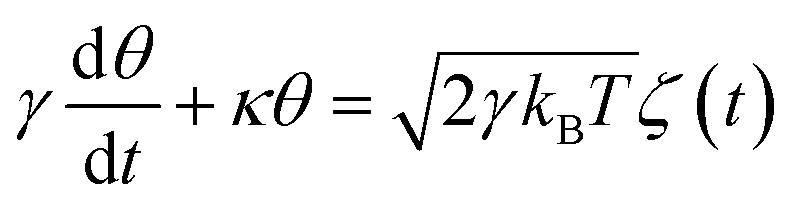 | (4) |
Then the final power spectral density (PSD) expression for the angle θ can be computed from the Fourier transform of eqn (4), as given by
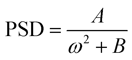 | (5) |
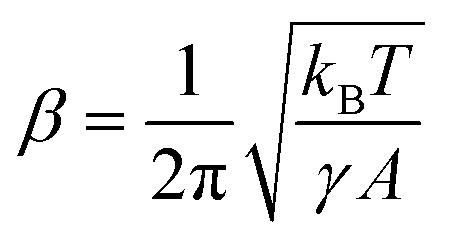
In the experiment the PSD is measured in V2 Hz−1 units as shown in Fig. 3 which has to be calibrated and converted to rad2 Hz−1 using a calibration factor (β)20–22 given as
 | (6) |
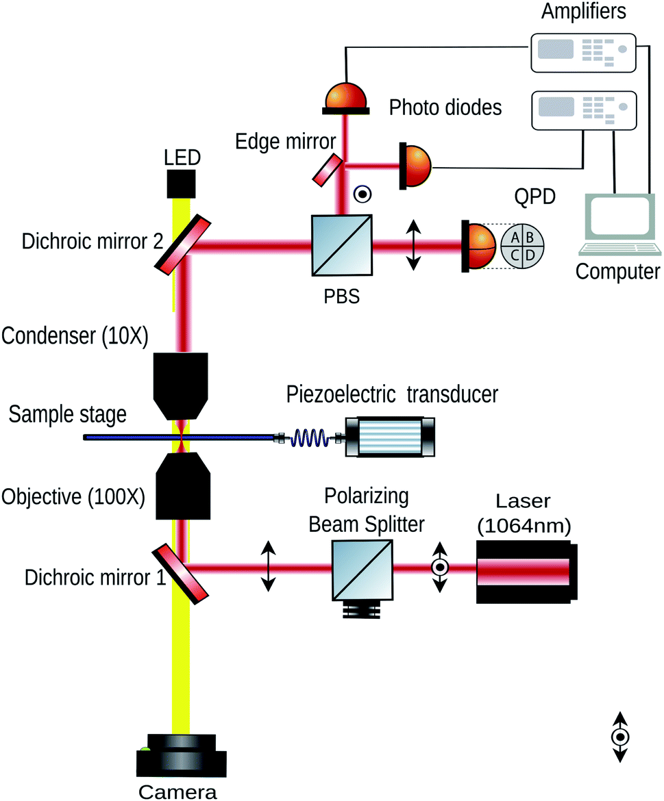 | ||
| Fig. 2 This figure shows the schematic diagram of the setup. The stage is moved by a piezoelectric transducer (PZT). | ||
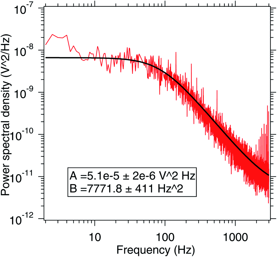 | ||
| Fig. 3 This figure shows the pitch power spectral density (PSD) for a trapped 3 μm diameter birefringent particle inside the sample chamber. This provides information about the A and B coefficients which can then be used to calibrate the pitch motion of the spherical particle while rolling on the substrate. | ||
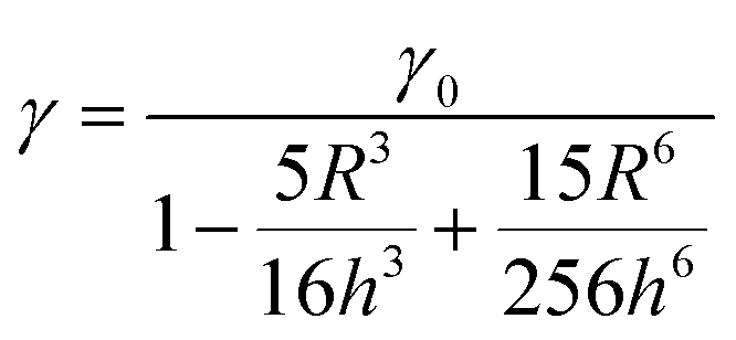
The rotational drag coefficient in bulk with viscosity η is γ0 = 8πηR3 following Stokes law. However, close to the surface the drag coefficient (γ) changes for both rotational23 and translational21 cases with radius of the particle R and the height (h) from the surface and is related to γ0 as given in eqn (7)
 | (7) |
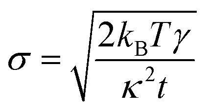
The time series for the motion of a particle inside a fluid medium is dominated by the Brownian motion. The expected root mean square (RMS) noise σ for a signal integrated over time t is given by the expression,24
 | (8) |
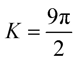
A spherical particle residing on a substrate has a circular contact area. The particle adheres to the surface and the radius (r) of contact region can be estimated using the Johnson–Kendall–Roberts (JKR) model for adhesive contacts25 in the absence of external compression forces as
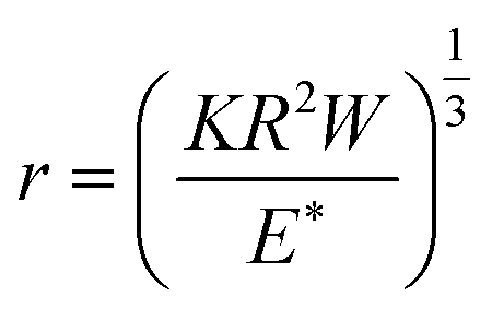 | (9) |
 , R is the radius of adherent particle, W is the work of adhesion, E* is the effective elastic modulus of the system calculated as
 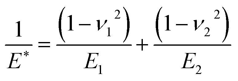 , ν1 (ν2) and E1 (E2) are the Poisson's ratio and Young's modulus of the particle (substrate) respectively.26
Further, the total adhesive energy (Ur) of the particle-substrate contact which encompass both the surface energy required to detach particle from the surface and elastic energy of the deformed adherent particle26 is given as
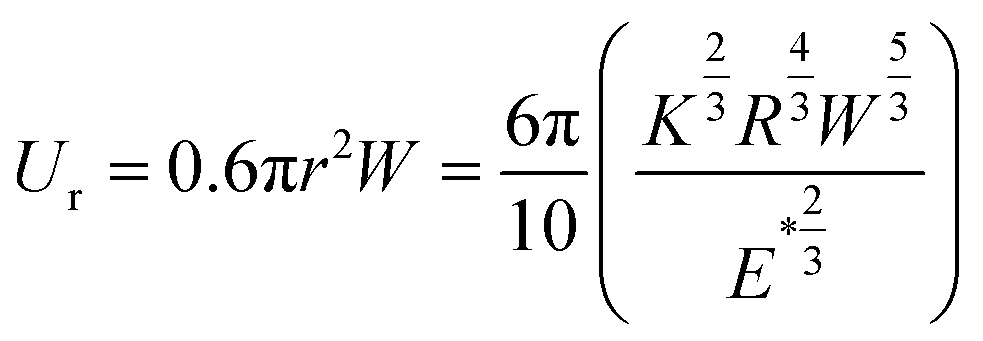 | (10) |
2 Experimental setup
We show the experimental setup used to generate the pitch motion in Fig. 2. We use the OTKB/M Optical Tweezers kit from Thorlabs, USA, to perform the experiment. Birefringent particles of 3 μm diameter suspended in 20 μl distilled water were placed between a glass slide (Blue star, 75 mm × 25 mm × 1.1 mm) and a coverslip (Blue star, number 1 size, english glass) to form the sample chamber. An oil immersion objective of 100×, 1.3 NA from Olympus with inverted microscope configuration is used trap the particles as shown in Fig. 2. The scattered light is then collected using an air condenser lens objective (E plan 10×, 0.25 air-immersion) (Nikon). A dichroic mirror and polarizing beam splitter (PBS) directs most of the scattered light towards a quadrant photodiode (QPD) to detect the translational motion of the trapped particle. Also, a white light source illuminates the sample chamber from the top coupled via the dichroic mirrors and the light is directed into a CMOS camera as shown in Fig. 2. The stage in the OTKB/M kit from Thorlabs, USA already has a piezoelectric transducer (PZT) which can be used to move the stage in all the three translational directions using appropriate drivers, also from Thorlabs.A diode laser (from Lasever, China) of wavelength 1064 nm was used in the experiment and focused onto the sample plane. The laser was linearly polarized to ensure that the birefringent particle axis aligned with it. The power used was about 70 mW at the sample plane.
Birefringent particles used in this experiment were synthesized from RM257 (Merck) nematic liquid crystal precursor powder. The preparation protocol requires 99% pure ethanol (50 ml) and de-ionised water (150 ml) in 1:3 ratio which were separately heated to 55 °C and 75 °C respectively. Temperatures of ethanol and water were monitored and when, ethanol reached 55 °C, about 80 mg of RM257 powder was added. The solution was then stirred with a small magnetic stirrer allowing the powder to dissolve uniformly. Subsequently, this RM257-ethanol solution was then added to de-ionised water in a drop-wise fashion. A milky white solution was formed in the beaker which is then closed with a perforated aluminium foil. Ethanol gradually evaporated from these perforations leaving the overall solution at 150 ml. Later, when the solution cooled down to room temperature we stored and used it for the experiments. The particles sizes synthesized using this method vary from 2 μm to 3 μm. The refractive index of the RM257 along the extraordinary axis is about 0.18 (the bulk birefringence) higher than that for the ordinary direction which is about 1.53.17
The diamond particles bearing NV centers used in the experiment were sourced from Adamas Nanotechnologies (MDNV1umHi10mg). These diamonds were dispersed in de-ionized water at a concentration of 1 mg ml−1. The particles have an average size of 500 nm with a distribution shown in Fig. 7(b) measured using dynamic light scattering analysis.
The poly dimethyl siloxane (PDMS) (Dow Corning's Sylgard 184 elastomer kit) substrate was prepared by curing silicone elastomer in 10% (W/W) with a curing agent. The viscous solution is spin coated onto glass slides and baked at a temperature of 150 °C.
The pitch motion is inferred from the difference in signals from the two photodiodes.20 Current preamplifiers PDA200C (Thorlabs) were placed on the outputs for the two photodiodes with a bandwidth of 20 KHz. A National Instruments data card NI-DAQ 6212 BNC with a data acquisition rate of 10 kilo samples per second has been used to acquire data for the time series. The acquired data was then running averaged over 5000 points to get the data shown in the pitch time series. The stage modulation rate is 1 Hz, well consistent with the bandwidth.
3 Results and discussions
We first calibrate the pitch motion of the birefringent particle by trapping it away from the surfaces and ascertaining the power spectral density of the thermal motion of the pitch mode of rotation.20,27 This has been shown in Fig. 3 and has been fitted to a Lorentzian. The pitch rotation detection works by taking the scatter pattern from the birefringent particle through crossed polarizers and then ascertain the difference in the halves of the scatter pattern. That signal is proportional to the pitch angle for small angular rotations.3.1 Rolling motion on glass
Using the fit parameters, the calibration factor of the rotational motion due to the stage motion is then estimated. The birefringent particle is then placed on the glass surface while held in the optical tweezers and then the stage is periodically moved along the direction tangential to the plane (in the X direction). The corresponding times series for the pitch motion and the X motion has been shown in Fig. 4. The size of the particle has been ascertained from the image which is well above the diffraction limit. The cross-section given in Fig. 4(c) shows an extent of about 20 pixels for the particle. Given that each pixel is 150 nm wide, that amounts to about 3 μm diameter for the particle.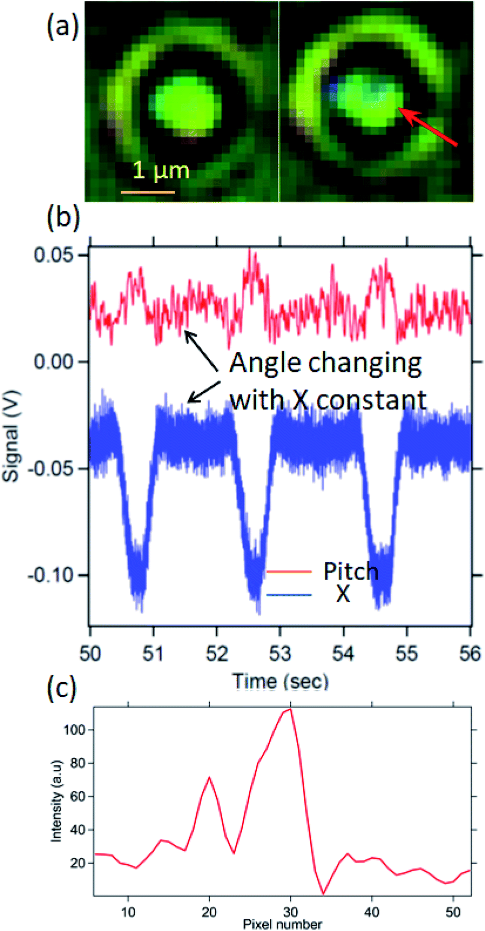 | ||
| Fig. 4 This figure shows the birefringent particle rolling on the glass substrate. In (a) we show how the scattered light pattern through the particle is getting altered when it rolls on the surface. In (b) we show the time series of the pitch angle (in red) and the x displacement of the particle (in blue). We are only concerned about the region of time when the particle is confined by the tweezers such that the X displacement is constant. It is then that the particle rolls on the surface. When the X displacement changes, the particle slips out of the adhesive influence of the surface. (c) The cross-section of the particle in the left image given in (a). Given that each pixel is 150 nm wide, the particle diameter is about 3 μm. | ||
It can be seen from the X time series that the X motion of the particle remains confined inside the trap for a part of time while it does slip out of the trap for the remainder of the period. We only consider the period time for which the particle is confined in the trap. We find that the pitch angle simultaneously changes while the particle is still confined in X direction inside the trap, indicating rolling motion. The calibrated pitch angle time series has been indicated in Fig. 5. There is a pitch rotation of about 20° while the stage moves by about 0.5 μm.
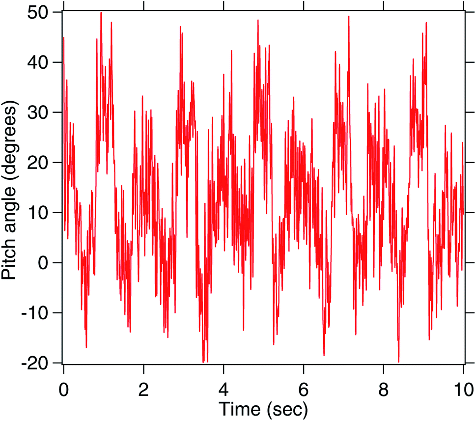 | ||
| Fig. 5 The same pitch angle in Fig. 4 but calibrated. We can see that the particle turns by 20 ± 7° without slipping. Here, the original time series has been smoothened over 5000 points. Considering that the original times series is sampled at 10 KHz, the final bandwidth is over 2 Hz, enough to see the rolling motion. | ||
The condition for rolling without slipping is nothing but the stage motion being related to the pitch angle as s = Rθ. The stage has been moved by 0.5 μm, such that the arc subtended this stage motion is then  . This is well consistent with the 20 ± 7° change of the pitch angle. Thus, the 1.5 μm radius birefringent particle executes rolling without slipping on the glass surface as the stage is moved.
We now try to find out the radius of the contact region, from the formula mentioned in eqn (9). We recall that in the aqueous environment, the work of adhesion is typically in the range of 1–100 mJ m−2. The corresponding radius of the contact area for a birefringent RM257 sphere, assumed similar to a polystyrene particle is (E1 = 2.3 GPa, ν1 = 0.35) with an R of 1.5 μm in contact with a flat glass substrate (E2 = 62 GPa, ν2 = 0.22) is then about 25 nm to 110 nm, for a work of adhesion ranging from 1 to 100 mJ m−2.
We then try to estimate the adhesive force due to the surface on the particle. In order to do that, we estimate that the torsional stiffness of the pitch motion given in Fig. 5 is (κ) 54700 pN nm rad−1. Then the torque that the birefringent particle can withstand without breaking from the surface is 19100 pN nm (κθ) and the energy 6667 × 10−21 J (as κθ2). This torque must be counteracted by the adhesive torque which is related to the work of adhesion. If the adhesive torque cannot withstand the torque due to the light, the particle will slip. Then for a range of radius from 25 to 100 nm, we get the work of adhesion as 0.2–3.4 mJ m−2 which is of the order of 1 mJ m−2.
Then the corresponding total adhesive energy of the contact is about 250kBT at W of about 1 mJ m−2. This is consistent with previous literature for birefringent particles on glass, with an R of 500 nm, when the energy of adhesion was about 50kBT.28
3.2 Surface effects (PDMS)
We now try to study the effect of the adhesivity of the surface on the rolling motion. We find that when a PDMS surface is used, the particle hardly rolls and mostly slips, as shown in Fig. 6.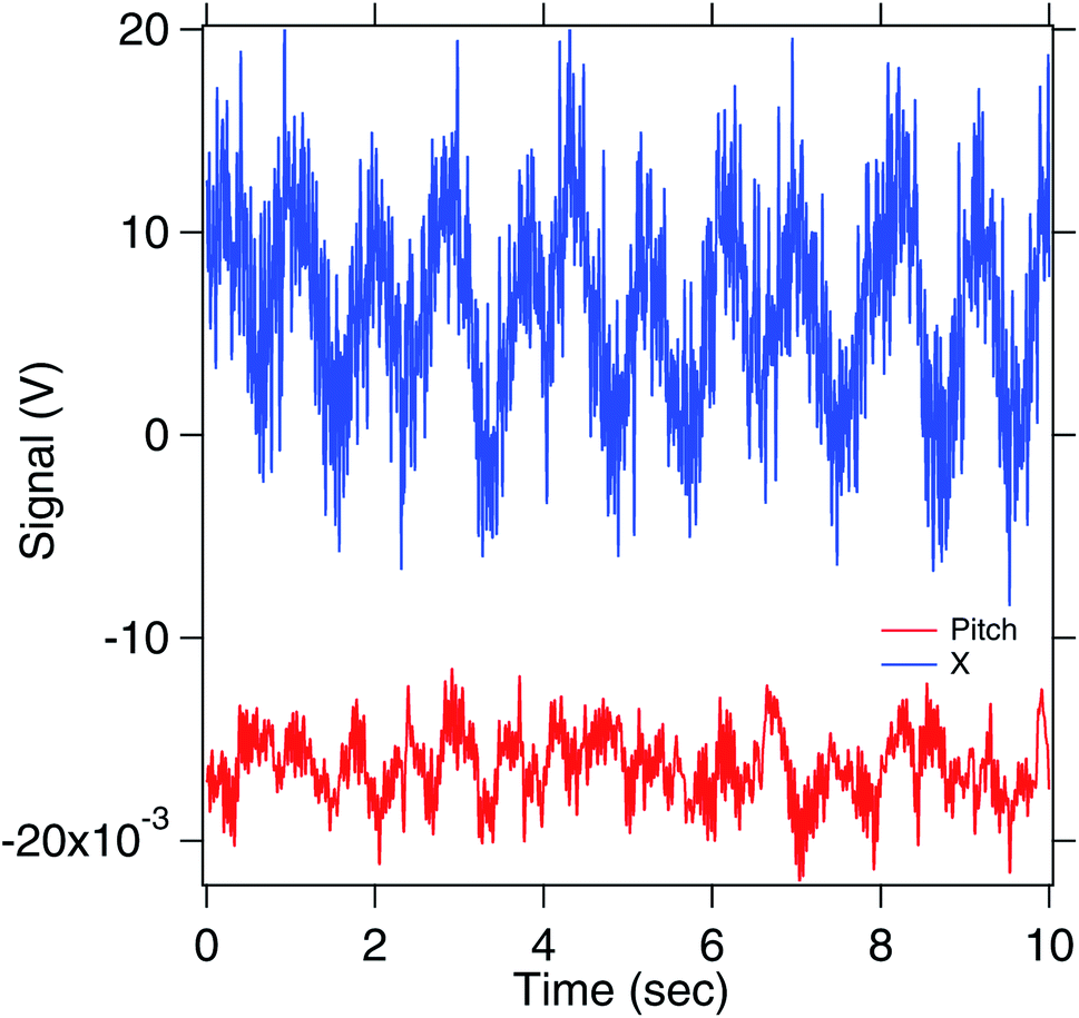 | ||
| Fig. 6 This figure shows the rolling with slipping that the birefringent particle experiences over a PDMS substrate. The pitch angle is given in red while the X motion is indicated in blue. The average change for the calibrated pitch signal is about 10 ± 7°. | ||
We find from the Fig. 6 that there is very less pitch rotational motion, while the particle moves in X. Thus, there is less rolling with more slipping, as is expected from a less adhesive hydrophobic surface.
3.3 Effects of particle size (diamond)
Finally, we realise that the 1.5 μm radius particle is very big with a large contact area with the substrate. Smaller birefringent particles of RM257 material often lose birefringence under 600 nm diameter. Thus we explore other particles which retain birefringence at small sizes as well. One such option is to use diamond particles of about 500 nm diameter. Diamond has a high refractive index of 2.417 and has been found to be difficult to trap in three dimensions if larger than about 200 nm diameter. It is generally believed that the scattering force becomes larger than the gradient force due to the tweezers and hence the particle gets pushed out of the trap.29,30 In one of the previous approaches, a 15 μm diameter particle was confined by surface tension to the air–water interface, trapped in tweezers and rotated in the yaw sense.31 It is here that we try to trap a 500 nm diameter particle very close to the top surface of the sample chamber that allows the scattering force to be compensated by the normal reaction of the surface. This approach confines the particle in two-dimensions and is called 2D trapping.32 These diamond particles also have a birefringence due to the stresses on the particle.33We use this in Fig. 7, and find that there is indeed rolling motion when the stage is moved. The corresponding radius of contact region, calculated using the eqn (9), considering that the diamond of radius 250 nm has a Young's modulus of 1050 GPa and Poisson ratio ν = 0.18 in contact with a flat glass substrate (E2 = 62 GPa, ν2 = 0.22), is about 25 nm. It may be noted here the diamond has a much higher Young's modulus than glass, and hence the system is in a different regime where the contact area is defined by the substrate.
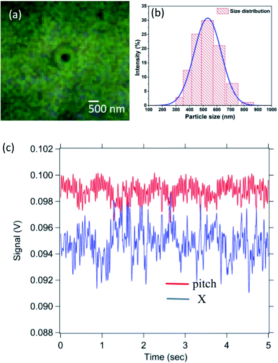 | ||
| Fig. 7 This figure shows the rolling with slipping that a diamond particle of 500 nm diameter experiences as the substrate is moved. In (a) we show an image of a diamond particle trapped almost on the substrate. In (b), we show the distribution of sizes for the diamond sample, studied using dynamic light scattering (DLS) and the average diameter is about 500 nm. In (c), we show the time series of motion. The pitch angle is given in red while the X motion is indicated in blue. | ||
We calibrate the time series of the pitch angle and find it about 20° (shown in Fig. 8) for a stage motion of 500 nm. Estimating the arc length subtended by the particle, as it turns by 20°, we find a length of about 90 ± 20 nm. This is much smaller than 500 nm length that the stage moves by. Thus there is rolling with slipping. Then the work of adhesion is about 0.9 mJ m−2.
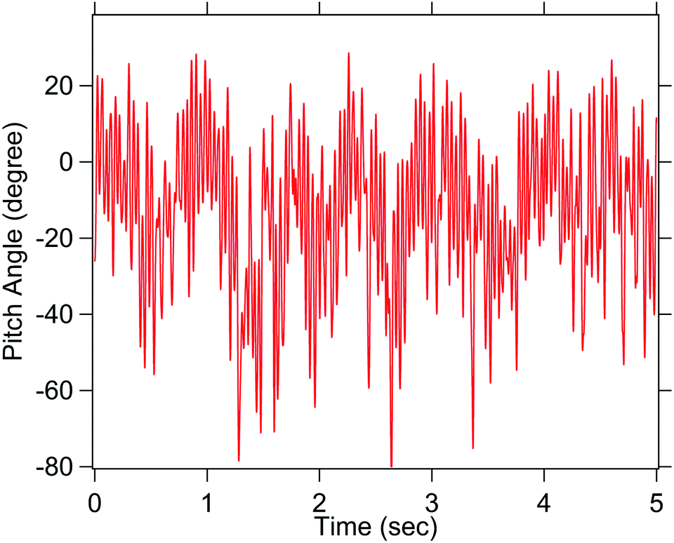 | ||
| Fig. 8 The same pitch time series as in Fig. 7(c) but calibrated. Even here, a rotation by 20° is seen. The X also changes during rolling indicating partial slipping. | ||
We had also tried performing the same experiment with even smaller diamond particles of 150 nm diameter but the irregularity of the surface of the particle seemed to reduce the contact area to very small radii. That system is a very different paradigm and is a true nanoscale probing, but we were unable to get good rolling motion. Moreover, our imaging system does not have phase contrast imaging so that we could not clearly visualise the particle. Thus, attempts at turning the particle in the pitch sense was inconclusive as these can also turn in yaw sense. This particular subdiffractive particle rolling motion study is beyond the scope of the present manuscript.
The work of adhesion estimated in this work is significantly smaller than that reported for similar surfaces performed at large forces using AFM where 50 mJ m−2 are often reported.11,34 Our work appears to be a case of soft probing of the surface by the optical tweezers. One can use this mode of soft probing to study interaction between protein coated particles on specific surfaces and ascertain the interaction energy which cannot be performed in any other way. We can also look for the effect of individual molecular bonds between the two surfaces.
The resolution of the pitch measurement can be improved by moving the stage even slower while averaging the time series over more points. The rotational time series obtained is dominated by Brownian noise, such that in order to gain a noise band of 1° RMS, an integration time of 100 ms is required for a 1.5 μm particle, from eqn (8). That gives a signal to noise ratio of 20 at 100 ms integration time, assuming a 20° rotation of the particle. Our integration time is 0.5 s, well higher than that, although we obtain 5° RMS noise band. Moreover, when the pitch rotational angle is less than 13° for a 1.5 μm radius particle moved by about 1 μm, we could say it is slipping.
4 Conclusions
In conclusion, we show a new method for estimating the work of adhesion of a surface at the nanoscale. Here, a birefringent particle is placed on a substrate and the stage moved parallel to the surface, such that the particle rolls. The extent of rolling provides information about the adhesivity of the surface. We show it for a RM257 particle of 3 μm diameter on glass surface and a PDMS surface. There is rolling without slipping only on the glass surface while it slips significantly on the PDMS surface. The work of adhesion for a birefringent particle on a glass surface is about 1 mJ m−2. This is significantly smaller than that reported for the work of adhesion for similar surfaces performed at large forces using AFM where 50 mJ m−2 are often reported. This appears to be a case of soft probing of the surface by the optical tweezers. Application of large force induces pressure on the surfaces to bind and hence the work of adhesion is larger. We then use a smaller 500 nm diameter diamond particle and show that there is rolling with slipping on the glass surface. This can be used to study adhesive properties of cells like leukocytes when rolled on different types of surfaces. There can be different types of protein coatings on the two surfaces and then the work of adhesion studied,35 which enables the study of interaction between binding molecules. We can also use the same method to turn the diamond bearing nitrogen vacancy (NV) centers by controllable angles while performing optical detected magnetic resonances (ODMR)33,36 on them, where the axis of the diamond crystal and the NV centers with respect to the magnetic field is critical.Author contributions
M. L., R. V., G. N. and S. R. performed the experiments and analysed data. B. R. designed the experiment, analysed data and wrote the manuscript. V. P. B. and A. P. analysed the data.Conflicts of interest
There are no conflicts to declare.Acknowledgements
We thank the Indian Institute of Technology, Madras, India for their seed and initiation grants. This work was also supported by the DBT/Wellcome Trust India Alliance Fellowship IA/I/20/1/504900 awarded to Basudev Roy. V. P. B. also thanks Department of Science and Technology, Government of India for the project DST/ICPS/QuST/Theme-2/2019/General.Notes and references
- R. P. McEver and C. Zhu, Annu. Rev. Cell Dev. Biol., 2010, 26, 363–396 CrossRef CAS PubMed.
- K.-C. Chang, D. F. Tees and D. A. Hammer, Proc. Natl. Acad. Sci. U. S. A., 2000, 97, 11262–11267 CrossRef CAS PubMed.
- M. R. King, International Conference on Nanochannels, Microchannels, and Minichannels, 2003, pp. 103–108 Search PubMed.
- Y. Geng, J. Marshall and M. R. King, Ann. Biomed. Eng., 2012, 40, 790–805 CrossRef PubMed.
- E. E. Edwards, J. Oh, A. Anilkumar, K. G. Birmingham and S. Thomas, Oncotarget, 2017, 8, 83585–83601 CrossRef PubMed.
- S. Blankenberg, S. Barbaux and L. Tiret, Atherosclerosis, 2003, 170, 191–203 CrossRef CAS PubMed.
- H.-B. Wang, J.-T. Wang, L. Zhang, Z. H. Geng, W.-L. Xu, T. Xu, Y. Huo, X. Zhu, E. F. Plow, M. Chen and J.-G. Geng, Nat. Immunol., 2007, 8, 882–892 CrossRef CAS PubMed.
- A. B. Yasunaga, Y. Murad, V. Kapras, F. Menard and I. T. Li, Biophys. J., 2021, 120, 2511–2520 CrossRef CAS PubMed.
- A. Yasanuga and I. T. S. Li, Sci. Adv., 2021, 7, eabe6984 CrossRef PubMed.
- S. Choi, J. M. Karp and R. Karnik, Lab Chip, 2012, 12, 1427–1430 RSC.
- Y. Jiang and K. T. Turner, Extreme Mechanics Letters, 2016, 9, 119–126 CrossRef.
- D. L. Sedin and K. L. Rowlen, Anal. Chem., 2000, 72, 2183–2189 CrossRef CAS PubMed.
- S. Adhikari, G. Frankel, B. D. Bammel and J. Zimmerman, J. Adhes. Sci. Technol., 2012, 26, 1591–1609 CrossRef CAS.
- M. M. Peri and C. Cetinkaya, J. Adhes. Sci. Technol., 2008, 22, 507–528 CrossRef CAS.
- L. Friedrich and A. Rohrbach, Nat. Nanotechnol., 2015, 10, 1064–1069 CrossRef CAS PubMed.
- M. E. Friese, T. A. Nieminen, N. R. Heckenberg and H. Rubinsztein-Dunlop, Nature, 1998, 394, 348–350 CrossRef CAS.
- A. Ramaiya, B. Roy, M. Bugiel and E. Schäffer, Proc. Natl. Acad. Sci. U. S. A., 2017, 114, 10894–10899 CrossRef CAS PubMed.
- S. Kumar, M. Gunaseelan, R. Vaippully, A. Kumar, M. Ajith, G. Vaidya, S. Dutta and B. Roy, Biomed. Opt. Express, 2020, 11, 3555–3566 CrossRef CAS PubMed.
- M. Lokesh, R. Vaippully and B. Roy, Asian J. Phys., 2020, 29, 177–182 Search PubMed.
- R. Vaippully, V. Ramanujan, M. Gopalakrishnan, S. Bajpai and B. Roy, Soft Matter, 2020, 16, 7606–7612 RSC.
- E. Schaffer, S. Norrelykke and J. Howard, Langmuir, 2007, 23, 3654–3665 CrossRef PubMed.
- K. Berg-Sorensen and H. Flyvberg, Rev. Sci. Instrum., 2004, 75, 594 CrossRef CAS.
- J. Leach, H. Mushfique, S. Keen, R. Di Leonardo, G. Ruocco, J. Cooper and M. Padgett, Phys. Rev. E: Stat., Nonlinear, Soft Matter Phys., 2009, 79, 026301 CrossRef CAS PubMed.
- P. Lebel, A. Basu, F. C. Oberstrass, E. M. Tretter and Z. Bryant, Nat. Methods, 2014, 11, 456–462 CrossRef CAS PubMed.
- K. L. Johnson, K. Kendall and a. Roberts, Proc. R. Soc. London, Ser. A, 1971, 324, 301–313 CAS.
- A. Jonas, M. Kochanczyk, A. D. Ramirez, M. Speidel and E.-L. Florin, Langmuir, 2019, 35, 5809–5820 CrossRef CAS PubMed.
- B. Roy, A. Ramaiya and E. Schaffer, J. Opt., 2018, 20, 035603 CrossRef.
- R. Vaippully, D. Bhatt, A. D. Ranjan and B. Roy, Phys. Scr., 2019, 94, 105008 CrossRef CAS.
- V. R. Horowitz, B. J. Aleman, D. J. Christle, A. N. Cleland and D. D. Awschalom, Proc. Natl. Acad. Sci. U. S. A., 2012, 109, 13493–13497 CrossRef CAS PubMed.
- M. L. Juan, C. Bradac, B. Besga, M. Johnsson, G. Brennen, G. Molina-Terriza and T. Volz, Nat. Phys., 2017, 13, 241–245 Search PubMed.
- C.-K. Sun, Y.-C. Huang, P. C. Cheng, H.-C. Liu and B.-L. Lin, J. Opt. Soc. Am. B, 2001, 18, 1483–1489 Search PubMed.
- H. Furukawa and I. Yamaguchi, Opt. Express, 1998, 23, 216–218 CAS.
- L. W. Russell, E. C. Dossetor, A. A. Wood, D. A. Simpson and P. J. Reece, ACS Photonics, 2021, 8, 1214–1221 CrossRef CAS.
- J. V. Escobar, C. Garza and R. Castillo, Beilstein J. Nanotechnol., 2017, 8, 813–825 CrossRef CAS PubMed.
- B. T. Marshall, M. Long, J. W. Piper, T. Yago, R. P. McEver and C. Zhu, Nature, 2003, 423, 190–193 CrossRef CAS PubMed.
- L. W. Russell, S. Ralph, K. Wittick, J. Tetienne, D. Simpson and P. J. Reece, ACS Photonics, 2018, 5, 4491–4496 CrossRef CAS.
Footnote |
| † Electronic supplementary information (ESI) available. See DOI: 10.1039/d1ra06960h |
| This journal is © The Royal Society of Chemistry 2021 |