 Open Access Article
Thermal insulation fibers with a Kevlar aerogel core and a porous Nomex shell†
Yueyan Sun ,
Weiwang Chen
 * and
Xiaomeng Zhou
Key Laboratory of Civil Aviation Thermal Hazards Prevention and Emergency Response, Civil Aviation University of China, Tianjin 300300, P. R. China. E-mail: ww_chen@cauc.edu.cn
First published on 27th October 2021
Abstract
Kevlar aerogel fibers which inherit the aerogel's brilliant properties of low density, high porosity and large surface area are promising candidates for thermal insulation applications in textiles. To enhance the mechanical strength of Kevlar aerogel fibers, an extra Nomex shell was introduced by a simple coaxial-wet-spinning approach. The resultant coaxial fibers were observed to have a Kevlar aerogel core and a porous Nomex shell. Besides, there also formed an air gap between the core and the shell. This multi-layered coaxial structure with numerous pores inside contributes to the excellent thermal insulation performance of the fibers and their fabrics. The temperature differences between the hot plate and the outer surface of the fabrics were measured to be as high as 80 °C when exposed to a temperature of 300 °C. In addition, these fibers also performed well in thermal stability, and almost did not decompose before 380 °C. Not only that, the breaking strength of the Nomex shell can be up to twice that of the Kevlar core, resulting in a significant improvement in the fiber's mechanical strength. It can be envisaged that the developed coaxial fibers with excellent thermal insulation and endurance properties as well as improved mechanical strength may have broad prospects for thermal insulation at high temperatures.
1. Introduction
Due to their unique nano-porous structure and the resulting properties of low density, high specific surface area, low thermal conductivity, etc., aerogels are promising for diverse applications, including waste disposal,1,2 catalysis,3 energy storage,4,5 thermal insulation,6–8 and so on. These aerogels are usually available as powders,9,10 particles,11,12 blocks,13–15 films,16 or fibers.17–19 Among them, aerogel powders are often used as functional fillers for thermal insulation because of their simplicity of preparation. However, they easily fall off in use. Besides, the air permeability of their coating fabrics tends to drop sharply, which limits the application of aerogel powders in protective clothing, such as suits for firefighting. Fabrics derived from aerogel fibers, however, can solve these problems well. This is also why aerogel fibers have received extensive attention.Up to now, there are a variety of compounds that can be processed into aerogel fibers. For example, noble metal composite aerogel fibers made from flexible and porous biopolymers can offer wide application prospects in catalysis and sensing.20 Du et al.21 prepared transparent silica aerogel fibers with low density, high specific surface area and flexibility. The obtained fibers inherited the advanced features of silica aerogel including excellent thermal insulation and wide temperature stability. Inspired by polar bear hair, Cui et al.22 fabricated silk fibroin solution into fibers with aligned porous microstructure. They placed the fabric braided from thus fibers on a hot plate of 80 °C. The temperature difference between the upper and lower surfaces of the fabric was 4.5 °C in a steady state. But the fabric cannot be used at high temperatures. Wang et al.23 proposed a series of polyimide aerogel fibers fabricated by freeze-spinning. These fibers performed well in heat endurance and showed amazing thermal insulation performance at high temperatures. Nevertheless, all the above aerogel fibers are either prone to pyrolyze when exposed to a relatively high temperature or require a complex preparation process, which is a serious limitation for their applications. In this case, aerogel fibers that are easy to obtain but have superior thermal stability are more eye-catching.
Poly-p-phenylene terephthamide (PPTA), also known as Kevlar, is one of the desired polymers for fabricating aerogel fibers that can meet thus needs.24,25 To fabricate Kevlar-derived aerogel fibers, the dispersion of Kevlar nanofibers (KNFs) always needs to be prepared at the very beginning. Yang et al.26 dissolved commercial Kevlar fibers in dimethyl sulfoxide (DMSO) and obtained KNFs under the deprotonation of potassium hydroxide (KOH). The resultant KNFs inherited the advantages of commercial Kevlar as their chemical structure was not destroyed by deprotonation. Using a similar dispersion, Liu et al.27 obtained Kevlar aerogel fibers with high mechanical strength and excellent thermal stability based on a wet-spinning technique. The thermal conductivity of their fibrous mat at room temperature was measured to be about 0.037 W m−1 K−1. Li et al.28 designed several symbiotic aerogel fibers from the combination of aramid nanofibers and polyamidoxime. These symbiotic fibers were hydrophilic and possessed high specific surface areas. Nevertheless, the mechanical strength of the Kevlar-derived aerogel fibers is yet to be improved, to give themselves better usability. Introducing an extra shell29–31 for Kevlar aerogel fibers could be a good choice.
In this work, we report a series of core–shell aerogel fibers casted by a simple coaxial-wet-spinning process, with Kevlar as the core and a consanguineous Nomex as the shell. The Kevlar core with interconnected nano-porous networks provides the resultant coaxial aerogel fibers extraordinary thermal blocking capability, while the Nomex shell provides them extra mechanical supports. Besides, the air gap formed between the core and the shell also enables these fibers better performance in thermal insulation. Their fabric products perform quite well in thermal insulation. Moreover, owing to the intrinsic heatproof nature of both Kevlar and Nomex, these fibers and their fabrics can withstand high temperatures in service. All these contribute the resultant coaxial aerogel fibers great potential for next-generation candidates in the fields of thermal insulation and heat management.
2. Experimental details
2.1 Materials
Commercial Kevlar and Nomex fibers were both supplied by Yantai Tayho Advanced Materials Co., Ltd. Dimethyl sulfoxide (DMSO), dimethylacetamide (DMAC), lithium chloride (LiCl) and ethanol were purchased from Aladdin Industrial Co., Ltd. Potassium hydroxide (KOH) was provided by Tianjin Fengchuan Chemical Reagent Co., Ltd.2.2 The preparation of spinning solutions
KNFs dispersion with a concentration of 1.5 wt% for the core was prepared by dispersing commercial Kevlar fibers in DMSO according to the previous reports.26,27 Nomex solutions of different concentrations were obtained by dissolving a certain amount of commercial Nomex fibers in DMAC in the presence of LiCl.32,33 The content of LiCl in the shell solutions was set as 2 wt% while the mass fraction of Nomex varied from 6% to 14%.2.3 The fabrication of coaxial aerogel fibers
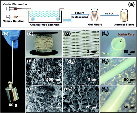
The schematic diagram of preparing coaxial aerogel fibers is shown in Fig. 1a, which involves a stepwise process of wet-spinning, sol-gelation and supercritical drying. As shown, the well-dispersed Kevlar dispersion and Nomex solution were extruded into a coagulation bath from a coaxial spinneret, to fabricate aerogel fibers with a core–shell structure. There were two kinds of coaxial spinnerets used in the present study. One was assembled by a 25G core needle and a 19G shell needle, while the other was assembled by a 28G core needle and a 21G shell needle. The inner diameters of these four needles can be seen in Table 1. During the process of coaxial-wet-spinning, the feeding speed of Kevlar dispersion and Nomex solution through the coaxial spinneret was fixed at 2 mL h−1 and 1.2 mL h−1, respectively. The extruded solution then gradually solidified in water to form wet gel fibers. The formed wet fibers after that were dialyzed for several times by using an 50% ethanol solution to conduct solvent replacement. Finally, a typical supercritical CO2 drying process was employed, to convert these wet fibers into aerogel fibers.| Coaxial spinneret | Group | No. | Polymer concentration for spinning/wt% | Fiber size/mm | ||||
|---|---|---|---|---|---|---|---|---|
| Core needle (diameter/mm) | Shell needle (diameter/mm) | Kevlar dispersion | Nomex solution | Diameter of Kevlar core | Wall thickness | Total diameter | ||
| 19G (0.75) | 25G (0.26) | 1 | 1–1 | 1.5 | 6 | 0.38 | 0.06 | 0.51 |
| 1–2 | 1.5 | 8 | 0.38 | 0.07 | 0.63 | |||
| 1–3 | 1.5 | 10 | 0.35 | 0.07 | 0.74 | |||
| 1–4 | 1.5 | 12 | 0.35 | 0.07 | 0.77 | |||
| 1–5 | 1.5 | 14 | 0.37 | 0.06 | 0.80 | |||
| 21G (0.45) | 28G (0.20) | 2 | 2–1 | 1.5 | 6 | 0.30 | 0.05 | 0.48 |
| 2–2 | 1.5 | 8 | 0.31 | 0.05 | 0.52 | |||
| 2–3 | 1.5 | 10 | 0.30 | 0.04 | 0.56 | |||
| 2–4 | 1.5 | 12 | 0.30 | 0.05 | 0.61 | |||
| 2–5 | 1.5 | 14 | 0.32 | 0.06 | 0.67 | |||
2.4 Characterization
The morphology of the resultant aerogel fibers was obtained by scanning electron microscopy (SEM, ZEISS Sigma 500). A microscope (GMW-500) was used to capture the overall and cross-sectional appearance of the coaxial fibers. The pore size distribution of the porous Nomex shell and the Kevlar aerogel core was measured based on the methods of mercury injection (AutoPore VI 9610) and nitrogen adsorption (Mike ASAP2460), respectively. The mechanical properties of the fibers were tested by an electronic universal testing machine (WDW-1 M) with a gauge length of 100 mm at a loading rate of 5 mm min−1. Thermo-gravimetric analysis (TGA) was performed on a Mettler TGA/DSC3+ with a heating rate of 10 °C min−1 from room temperature to 700 °C in N2 atmosphere. Besides, we further braided these coaxial fibers into fabrics, to evaluate their thermal insulation capability by putting them on a hot plate. The temperature differences between the outer surface of the fabric and the hot plate were recorded.3. Results and discussion
3.1 Microstructure and morphology
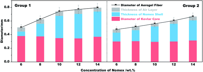
As can be seen from Fig. 1b, a single coaxial fiber can easily withstand a strain relief test of 50 g, which means that the resultant fibers have considerable mechanical strength. Fig. 1c shows what coaxial aerogel fibers prepared using a 14 wt% Nomex solution together with a 21G–28G coaxial spinneret look like when coiled. The surface and cross-sectional appearance of the aerogel fibers characterized by microscopy are given in Fig. 1d–f. It is obvious that the surface of the aerogel fibers is smooth and glossy with creamy white in color. For the fiber's cross-section, there is an air gap between the core fiber and the outer shell. The total diameters of the fibers show an increasing tendency from 0.48 mm to 0.67 mm as the concentration of Nomex solution increases from 6 wt% to 14 wt% (see Fig. 2). Obviously, the total diameters of the fibers are bigger than the corresponding spinneret diameter (see Table 1). This is because of the Barus effect,34,35 extrusion swell effect in other words, which is a familiar phenomenon for polymer solution when it was extruded from a die. The fiber diameter of the Kevlar core and the thickness of the Nomex shell, however, both maintain stable at about 0.3 mm and 0.05 mm, respectively. A similar result was also observed for the aerogel fibers obtained by the 19G–25G coaxial spinneret. That is, the gap between the core and the shell increases gradually as the concentration of Nomex increases. The immiscibility between Kevlar dispersion and Nomex solution should be the main reason (see Fig. S1 in the ESI†). It causes these two polymers to precipitate when they meet each other after being extruded, forming a separate gap at the interface. The gap then extends due to the existence of Barus effect. Not only that, the Barus effect seems to be more significant at higher polymer concentrations. The diameter of the sample 2–1 increased by about 7% compared to the diameter of the needle, while the diameter of the sample 2–5 is much larger, about 1.5 times that of the needle. In addition, the difference of Kevlar core and Nomex shell in shrinkage resistance during drying may also widen the gap further. To verify this, the diameters of a given coaxial fiber before and after drying were measured. From Fig. S2 in the ESI,† it was found that the total diameter of the given fiber after drying almost the same as that before drying, even if the fiber was naturally air-dried. In contrast, the Kevlar core dried in the absence of supercritical fluids shrank severely. It means that the Nomex shell has a much better shrinkage resistance ability than the Kevlar core. The thickness of the gap between the Nomex shell and Kevlar core therefore may increase further in the process of drying. Given these, the occurrence of an extra air gap ranging from 0.1 mm to 0.4 mm is not a surprise.Fig. 1d1 and d2 show the interconnected three-dimensional network of the Kevlar core. It is apparent that the core fiber has a typical aerogel structure assembled by numerous Kevlar nanofibers. The network aperture distribution belongs to nanoscale aperture. There are almost no macropores observed. But the structure of the Nomex shell is very different, as shown in Fig. 1e1 and e2. In the shell, there formed many pores with the diameters ranging from several to tens of micrometers. It can be described as a multi-void structure that also contains a pile of fibers. That is to say, the prepared fibers have a multi-layered coaxial structure with aerogel core and a porous non-aerogel shell.
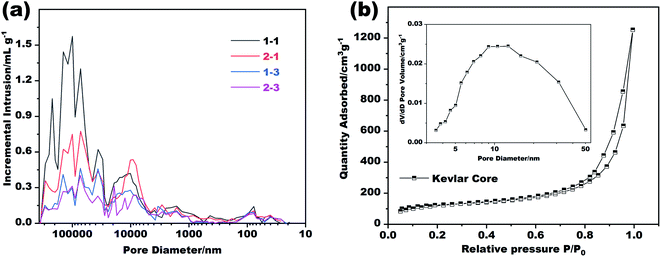
Further tests were carried out to explore the details of the pores inside the Kevlar core and the Nomex shell. Of the two, the distribution of the aerogel pores inside the Kevlar core was analyzed by a typical nitrogen absorption and desorption method, while the distribution of Nomex shell pores was analyzed by using a mercury porosimeter due to their relatively larger pore size (see Fig. 1e). The results are shown in Fig. 3. It can be seen from Fig. 3a that the diameter of most pores inside the Nomex shell falls between 10 μm to 100 μm. The larger the spinneret diameter, the more pores larger than 1 μm seems to be. It is because that the larger diameter of spinneret (see Table 1), the larger volume of Nomex shell per unit length. The shell with larger volume therefore could have more pores at the same concentration of Nomex. In addition, by comparing the curves of sample 1–1 with sample 1–3 in Fig. 3a, it can be given that the higher the concentration of Nomex, the less the pores at the micron level. The same is true for sample 2–1 and sample 2–3. These pores inside the Nomex shell can also provide additional thermal insulation to the fibers. Fig. 3b gives the obtained nitrogen absorption and desorption isotherms as well as the pore size distribution of the Kevlar core. Obviously, most of the pores inside the Kevlar core are mesoporous, in consistent with the SEM images in Fig. 1d. The result confirms that the Kevlar core has a typical aerogel structure, which is bound to give the core an excellent performance in thermal insulation.
3.2 Thermal properties
Thermogravimetric analysis (TGA) was conducted to investigate the thermal stability of the obtained fibers. The results are plotted in Fig. 4a, which show that the prepared fibers have an outstanding advantage in high-temperature resistance. From the TG curves in Fig. 4a, the weight loss occurred below 120 °C should be due to the removal of CO2 absorbed during drying as well as the evaporation of moisture and remaining solvents. While that is almost zero within 120 °C and 380 °C. After that, a significant weight loss resulting from the thermal decomposition of Nomex then appears. As the temperature further increases to more than 460 °C, Kevlar then reaches its pyrolysis temperature and begins to decompose.33 It is apparent that the coaxial fibers that prepared with the same Nomex solution but different spinnerets have similar TG curves. Besides, the prepared fibers also show excellent ability in forming char. The residue remained at 700 °C for these four samples are about 51% of their initial weight. This is crucial for thermal protective polymers, because the carbon residue formed by polymer pyrolysis with porous structure can block the external heat, and thereby provide a shield to reduce heat injury to the objects being protected.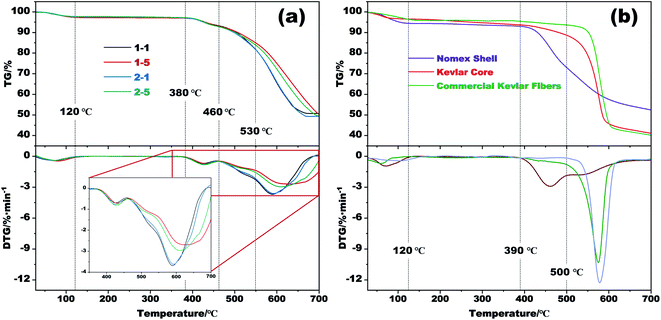 | ||
| Fig. 4 (a) TG and DTG curves of several respective aerogel fibers. (b) TG and DTG curves of the Nomex shell and the Kevlar core of sample 1–5 as well as commercial Kevlar fibers. | ||
Considering that the aerogel fibers are made up of two different polymers, TG tests of the Kevlar core and the Nomex shell were also carried out separately. The results are shown in Fig. 4b, together with the TG curve of commercial Kevlar fibers. The derivative thermogravimetric (DTG) curve in this figure shows that the decomposition of the Nomex shell has two stages within 390 °C and 600 °C, which correspond to the heterolysis and hemolysis of the polymer, respectively.36 As the temperature rises above 600 °C, the dehydrogenation and condensation reactions then occur.36,37 The residue for Nomex shell is about 52% of its initial weight at 700 °C. By comparison, the thermal degradation of Kevlar core mainly happens above 460 °C, which is similar to the pyrolysis behavior of commercial Kevlar fibers although slightly worse. That is, fabricating Kevlar from commercial fibers into aerogel did not significantly deteriorate its thermal stability. Given that the coaxial fibers are made up by Nomex shell and Kevlar core, the onset temperature for the fibers to decompose is therefore in accordance with that of pure Nomex shell. The fibers then undergo rapid decomposition above 460 °C owing to the decomposition of Kevlar core. Besides, comparing the DTG curves of sample 1–1 with sample 1–5 (or 2–1 with 2–5) in Fig. 4a, it is observed that an increase in Nomex concentration slightly slows down the decomposition of the fibers. The temperature corresponding to the maximum weight loss rate also increases from about 590 °C to 610 °C. The reason for the difference is that the decomposition of Nomex shell is slower than Kevlar core within the temperature range of 500–600 °C. And at the same time, the Nomex content of sample 1–5 (or 2–5) is higher than that of sample 1–1 (or 2–1), as the result of the use of a higher-concentration Nomex solution (see Table 1). The sample 1–5 (or 2–5) with more Nomex incorporated thus has a slower decomposition rate than sample 1–1 (or 2–1) above 460 °C.
The above results indicate that the excellent thermal stability of Kevlar is well reserved even after processed into aerogel fibers. Besides, the introduction of Nomex that decomposes at a relatively lower temperature makes the thermal stability of the coaxial fibers slight worse than that of pure Kevlar. Nevertheless, the resultant coaxial fibers still show excellent performance in thermal stability and may have a good application prospect in high temperature applications.
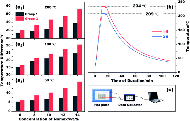
The thermal insulation property of the resultant fibers was evaluated by placing their braided fabrics on a hot plate of different temperatures. The fabrics braided are 2 cm × 4 cm in size, and are divided into group 1 and group 2 according to the fibers used (see Table 1). The temperature of the hot plate was set to 50 °C, 100 °C, 200 °C and 300 °C in sequence. In the process of heating, the temperature difference between the hot plate and the outer surface of each fabric was recorded. The results and the schematic diagram for testing are plotted in Fig. 5. It is apparent that the temperature difference recorded varies with spinneret size and Nomex concentration. If we set the temperature of the hot plate at 50 °C, the outer surface temperature of the braided fabric suffers a gradual decrease from 43.8 °C to 33.7 °C as the Nomex concentration increases from 6 wt% to 14 wt%. The result is congenial with common sense. In this study, a higher Nomex concentration for shell means a larger total diameter of the prepared coaxial fibers (see Fig. 2). The fabric braided from thus fibers therefore tends to be thicker. Besides, the higher the concentration of Nomex, the thicker the air gap around Kevlar core. The resulted thicker fabric and air gap contribute to the fabric's better performance in thermal insulation. This was recorded as a lower surface temperature of the fabric, i.e., a larger temperature difference value between the hot plate and the outer surface of the fabric when exposed to the hot plate of the same temperature.
As the temperature of the hot plate increases, the temperature difference increases as well. This means that the fabrics braided from coaxial fibers still good at thermal insulation for high-temperature applications. If we adjust the temperature of the heating plate to 300 °C, the outer surface temperatures of the fabrics braided from fibers of 1–5 and 2–5 are measured to be 234.0 °C and 209.0 °C, respectively. The differences between them and the hot plate can be as high as 80 °C. Not only that, the fabrics can keep their shapes stable even after being heated at such a high temperature. The prepared fibers and their fabric products with proud flame retardancy27 therefore may have broad prospects in thermal insulation for high-temperature applications, such as firefighting protective clothing. Note that, the current fabrics are sparse to some extent, as shown in Fig. 1g. There is no doubt that the heat transfer through the gaps between the fibers has degraded the thermal insulation performance of the fabrics. These fabrics need to be densified further in future studies.
3.3 Mechanical strength
Uniaxial tensile tests were carried out to evaluate the mechanical strength of the coaxial fibers fabricated from different conditions. The results are plotted in Fig. 6. For ease of analysis, we used the total diameter of each fiber to obtain its stress–strain curve. As shown in Fig. 6a, there are two peaks in all stress–strain curves, of which the first one is due to the fracture of the outer shell while the second one is of the fracture of the inner core. Kevlar core and Nomex shell are tested for verification, respectively. The peaks of fracture are same with the results of coaxial fibers. As the Kevlar suspension used to prepare the core is the same, the breaking strength of the core fiber therefore is almost the same, about 0.55 MPa. The results in Fig. 6a also reveal that the first breaking strength of the resultant fibers increases significantly with increasing Nomex concentration in the shell. More specifically, the breaking strength of the Nomex shell is lower than that of the Kevlar core when the concentration of Nomex for the shell is below 10 wt%. As the concentration of Nomex reaches above 10 wt%, however, the Nomex shell tends to be more robust than the Kevlar core. The strength for the Nomex shell to break at a Nomex concentration of 14 wt% was measured to be 1.03 MPa, about twice that of the Kevlar core fiber. The higher the concentration of Nomex, there will be more polymer per unit area to against the tensile force, and therefore the greater the breaking strength. For the same reason, the growth rate of stress to strain before fracture for the shell also increases as the concentration of Nomex increases. The results indicate that increasing the concentration of Nomex in the shell solution can provide better reinforcement for the Kevlar aerogel fiber in the core. Therefore, shell solutions with Nomex concentrations above 10 wt% are preferred. This provides an effective strategy for enhancing the mechanical property of Kevlar aerogel fibers.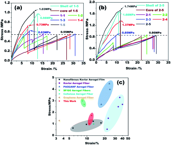 | ||
| Fig. 6 (a and b) Stress–strain curves of the coaxial fibers extruded from different spinnerets. (c) Comparison of mechanical strength at break of coaxial aerogel fibers in this study with other aerogel fibers (including nanofibrous Kevlar aerogel film,38 Kevlar aerogel fiber,27 PAO@ANF aerogel fiber,28 SF/GO aerogel fiber,31 cellulose aerogel fiber39 and graphene aerogel fiber40). | ||
Fig. 6b plots the stress–strain curves of the rest fibers prepared using a 21G–28G coaxial spinneret. The trend of these curves is similar to those in Fig. 6a. When the concentration of Nomex is higher than 10 wt%, the mechanical strength of the fibers is also greatly enhanced. But the first breaking strength of sample 2–5 is as high as 1.74 MPa, which is 1.7 times that of sample 1–5. The second breaking strength derived from the fracture of Kevlar core fiber also increases from 0.56 MPa to 0.85 MPa. This is mainly because that the stress–strain curves of the fibers were calculated by dividing the force by their total diameters. Although the aerogel fibers with the same Nomex solution is extruded from different spinnerets, the force at the second breaking has tiny difference (see Table S1 in the ESI†). Coaxial fibers of group 2 that have thinner diameters therefore show a higher breaking stress of about 0.85 MPa. This result is therefore no longer puzzling. By comparing with other similar aerogel fibers (see Fig. 6c), the coaxial aerogel fibers in the present study are competitive among them.
4. Conclusion
In this study, coaxial fibers with a Kevlar aerogel core and a porous Nomex shell were prepared based on coaxial-wet-spinning strategy. The structure, thermal properties as well as mechanical strength of the prepared fibers were characterized. The porous structure of the Kevlar core and Nomex shell together with air gap between them determined that the coaxial fibers and their fabrics possessed excellent thermal insulation. The temperature of fabrics' outer surface was lower than the hot plate about 80 °C when exposed to 300 °C. Besides, the resultant coaxial fibers still showed excellent performance in thermal stability which barely decomposed below 380 °C. More importantly, the introduction of Nomex shell gave the coaxial fibers better mechanical strength. The breaking strength of the Nomex shell can be up to twice that of the Kevlar core. Given these, the coaxial aerogel fiber might be a promising material for next-generation of thermal insulating fiber.Conflicts of interest
The authors declare that they have no conflict of interest.Acknowledgements
This work was supported by National Natural Science Foundation of China (Grant No. 51904312) and Scientific Research Foundation of Civil Aviation University of China (2020KYQD115). The authors are deeply grateful to these supports.References
- H. Sun, Z. Xu and C. Gao, Adv. Mater., 2013, 25, 2554–2560, DOI:10.1002/adma.201204576.
- F. Jiang and Y. Hsieh, J. Mater. Chem. A, 2014, 2, 6337–6342, 10.1039/c4ta00743c.
- Z. Wu, S. Yang, Y. Sun, K. Parvez, X. Feng and K. Muellen, J. Am. Chem. Soc., 2012, 134, 9082–9085, DOI:10.1021/ja3030565.
- Y. Zhao, J. Liu, Y. Hu, H. Cheng, C. Hu, C. Jiang, L. Jiang, A. Cao and L. Qu, Adv. Mater., 2013, 25, 591–595, DOI:10.1002/adma.201203578.
- M. Hamedi, E. Karabulut, A. Marais, A. Herland, G. Nystrom and L. Wagberg, Angew. Chem., Int. Ed., 2013, 52, 12038–12042, DOI:10.1002/anie.201305137.
- A. Neugebauer, K. Chen, A. Tang, A. Allgeier, L. R. Glicksman and L. J. Gibson, Energy Build., 2014, 79, 47–57, DOI:10.1016/j.enbuild.2014.04.025.
- R. Baetens, B. P. Jelle and A. Gustavsen, Energy Build., 2011, 43, 761–769, DOI:10.1016/j.enbuild.2010.12.012.
- A. Saboktakin and M. R. Saboktakin, Int. J. Biol. Macromol., 2015, 72, 230–234, DOI:10.1016/j.ijbiomac.2014.08.024.
- J. Wang, Y. Wei, W. He and X. Zhang, RSC Adv., 2014, 4, 51146–51155, 10.1039/c4ra10607e.
- A. Stojanovic, S. Zhao, E. Angelica, W. J. Malfait and M. M. Koebel, J. Sol-Gel Sci. Technol., 2019, 90, 57–66, DOI:10.1007/s10971-018-4879-4.
- K. Ganesan, T. Budtova, L. Ratke, P. Gurikov, V. Baudron, I. Preibisch, P. Niemeyer, I. Smirnova and B. Milow, Materials, 2018, 11, 2144, DOI:10.3390/ma11112144.
- B. Schroeter, V. P. Yonkova, N. A. M. Niemeyer, I. Jung, I. Preibisch, P. Gurikov and I. Smirnova, Cellulose, 2021, 28, 223–239, DOI:10.1007/s10570-020-03555-2.
- T. Zheng, A. Li, Z. Li, W. Hu, L. Shao, L. Lu, Y. Cao and Y. Chen, RSC Adv., 2017, 7, 34461–34465, 10.1039/c7ra04904h.
- B. Liu, M. Gao, X. Liu, Y. Xie, X. Yi, L. Zhu, X. Wang and X. Shen, RSC Adv., 2018, 8, 41603–41611, 10.1039/c8ra08263d.
- Z. Liu, Y. Chen, W. Dai, Y. Wu, M. Wang, X. Hou, H. Li, N. Jiang, C. Lin and J. Yu, RSC Adv., 2018, 8, 1065–1070, 10.1039/c7ra11574a.
- S. R. Kwon, J. Harris, T. Zhou, D. Loufakis, J. G. Boyd and J. L. Lutkenhaus, ACS Nano, 2017, 11, 6682–6690, DOI:10.1021/acsnano.7b00790.
- H. Yu, H. Hong, S. M. Kim, H. C. Ko and H. S. Jeong, Carbohydr. Polym., 2020, 240, 116348, DOI:10.1016/j.carbpol.2020.116348.
- R. Arat, H. Baskan, G. Ozcan and P. Altay, J. Ind. Text., 2020, 2025636879, DOI:10.1177/1528083720939670.
- S. Meng, J. Zhang, W. Chen, X. Wang and M. Zhu, Microporous Mesoporous Mater., 2019, 273, 294–296, DOI:10.1016/j.micromeso.2018.07.021.
- A. Mitropoulos, F. Burpo, C. Nguyen, E. Nagelli, M. Ryu, J. Wang, R. Sims, K. Woronowicz and J. Wickiser, Materials, 2019, 12, 894, DOI:10.3390/ma12060894.
- Y. Du, X. Zhang, J. Wang, Z. Liu, K. Zhang, X. Ji, Y. You and X. Zhang, ACS Nano, 2020, 14, 11919–11928, DOI:10.1021/acsnano.0c05016.
- Y. Cui, H. Gong, Y. Wang, D. Li and H. Bai, Adv. Mater., 2018, 30, 1706807, DOI:10.1002/adma.201706807.
- Y. Wang, Y. Cui, Z. Shao, W. Gao, W. Fan, T. Liu and H. Bai, Chem. Eng. J., 2020, 390, 124623, DOI:10.1016/j.cej.2020.124623.
- F. Vollrath and D. P. Knight, Nature, 2001, 410, 541–548, DOI:10.1038/35069000.
- J. Zhu, M. Yang, A. Emre, J. H. Bahng, L. Xu, J. Yeom, B. Yeom, Y. Kim, K. Johnson, P. Green and N. A. Kotov, Angew. Chem., Int. Ed., 2017, 56, 11744–11748, DOI:10.1002/anie.201703766.
- M. Yang, K. Cao, L. Sui, Y. Qi, J. Zhu, A. Waas, E. M. Arruda, J. Kieffer, M. D. Thouless and N. A. Kotov, ACS Nano, 2011, 5, 6945–6954, DOI:10.1021/nn2014003.
- Z. Liu, J. Lyu, D. Fang and X. Zhang, ACS Nano, 2019, 13, 5703–5711, DOI:10.1021/acsnano.9b01094.
- J. Li, J. Wang, W. Wang and X. Zhang, Molecules, 2019, 24, 1821, DOI:10.3390/molecules24091821.
- H. Yang, Z. Wang, Z. Liu, H. Cheng and C. Li, Polymers, 2019, 11, 1899, DOI:10.3390/polym11111899.
- J. Zhou and Y. Hsieh, Nano Energy, 2020, 68, 10435, DOI:10.1016/j.nanoen.2019.104305.
- Z. Wang, H. Yang, Y. Li and X. Zheng, ACS Appl. Mater. Interfaces, 2020, 12, 15726–15736, DOI:10.1021/acsami.0c01330.
- T. Wang, C. Zhao, P. Li, Y. Li and J. Wang, J. Membr. Sci., 2015, 477, 74–85, DOI:10.1016/j.memsci.2014.12.038.
- J. Lyu, X. Wang, L. Liu, Y. Kim, E. K. Tanyi, H. Chi, W. Feng, L. Xu, T. Li, M. A. Noginov, C. Uher, M. D. Hammig and N. A. Kotov, Adv. Funct. Mater., 2016, 26, 8435–8445, DOI:10.1002/adfm.201603230.
- J. Z. Liang, Polym. Test., 2008, 27, 936–940, DOI:10.1016/j.polymertesting.2008.08.001.
- N. Dukhan and K. P. Patel, Porous Media and its Applications in Science, Engineering and Industry, 2010, vol. 1254, pp. 299–304, DOI:10.1063/1.3453828.
- S. Villar-Rodil, A. Martinez-Alonso and J. Tascon, J. Anal. Appl. Pyrolysis, 2001, 58, 105–115, DOI:10.1016/S0165-2370(00)00124-8.
- S. Villar-Rodil, J. I. Paredes, A. Martinez-Alonso and J. Tascon, Chem. Mater., 2001, 13, 4297–4304, DOI:10.1021/cm001219f.
- J. Lyu, Z. Liu, X. Wu, G. Li, D. Fang and X. Zhang, ACS Nano, 2019, 13(2), 2236–2245, DOI:10.1021/acsnano.8b08913.
- J. Wan, J. Zhang, J. Yu and J. Zhang, ACS Appl. Mater. Interfaces, 2017, 9, 24591–24599, DOI:10.1021/acsami.7b06271.
- G. Li, G. Hong, D. Dong, W. Song and X. Zhang, Adv. Mater., 2018, 30, 1801754, DOI:10.1002/adma.201801754.
Footnote |
| † Electronic supplementary information (ESI) available. See DOI: 10.1039/d1ra06846f |
| This journal is © The Royal Society of Chemistry 2021 |

