 Open Access Article
Composite photocatalysts based on Cd1−xZnxS and TiO2 for hydrogen production under visible light: effect of platinum co-catalyst location†
Angelina V. Zhurenok,
Dina V. Markovskaya,
Evgeny Yu. Gerasimov ,
Svetlana V. Cherepanova,
Andrey V. Bukhtiyarov
 and
Ekaterina A. Kozlova
 *
*
Federal Research Center Boreskov Institute of Catalysis, 630090, Pr. Ak. Lavrentieva, 5, Novosibirsk, Russia. E-mail: kozlova@catalysis.ru; Fax: +7-383-326-95-43; Tel: +7-383-326-95-43
First published on 25th November 2021
Abstract
Ternary composite photocatalysts based on titania and solid solutions of CdS and ZnS were prepared and studied by a set of physicochemical methods including XRD, XPS, HRTEM, UV-vis spectroscopy, and electrochemical tests. Two synthetic techniques of platinization of Cd1−xZnxS/TiO2 were compared. In the first case, platinum was deposited on the surface of synthesized Cd1−xZnxS (x = 0.2–0.3)/TiO2 P25; in the second one, Cd1−xZnxS (x = 0.2–0.3) was deposited on the surface of Pt/TiO2 P25. The photocatalytic properties of the obtained samples were compared in the hydrogen evolution from TEOA aqueous solution under visible light (λ = 425 nm). The Cd1−xZnxS (10–50 wt%; x = 0.2–0.3)/Pt (1 wt%)/TiO2 photocatalysts demonstrated much higher photocatalytic activity than the Pt (1 wt%)/Cd1−xZnxS (10–50 wt%; x = 0.2–0.3)/TiO2 ones. It turned out that the arrangement of platinum nanoparticles precisely on the titanium dioxide surface in a composite photocatalyst makes it possible to achieve efficient charge separation according to the type II heterojunctions and, accordingly, a high rate of hydrogen formation. The highest photocatalytic activity was demonstrated by 20% Cd0.8Zn0.2S/1% Pt/TiO2 in the amount of 26 mmol g−1 h−1 (apparent quantum efficiency was 7.7%) that exceeds recently published values for this class of photocatalysts.
1. Introduction
Currently, particular attention is focused on novel methods for renewable energy production. The finite nature of fossil resources (such as coal, crude oil, and natural gas) stimulates the search for and development of alternative energy technologies and fuel sources. Hydrogen is considered as the most prospective fuel.1–3 However, current hydrogen production capacities are obviously insufficient for making significant progress towards hydrogen energy. Photocatalytic hydrogen production attracts particular attention as it, first, uses renewable sources, such as water and solar light, and, second, integrates hydrogen evolution and water purification from organic impurities,4–6 and thus ensures environment-friendly energy generation.Triethanolamine (TEOA) is one of the most popular sacrificial reagents.4–6 It has a wide range of application areas, for example, surfactant production, medicine, cosmetology, etc. Purification of water from TEOA is an important practical task. It is well-known that photocatalytic methods allow one to decompose various organic compounds, including amines,7–15 with hydrogen evolution. Photocatalytic hydrogen production from aqueous TEOA solutions is often carried out over g-C3N4-based4,5,8–10 or composite g-C3N4/TiO2-based11–15 photocatalysts. Titanium dioxide is most often used as a semiconductor photocatalyst for various applications, because TiO2 is a relatively cheap and non-toxic material.16–18 The main disadvantage of using pure TiO2 for photocatalytic hydrogen production is its insensitivity to visible light owing to wide band gap of 3.2 eV,19 and, consequently, low-efficient functioning under the influence of sunlight. An effective method for sensitizing titanium dioxide is the creation of composite systems with interfacial heterojunctions, in which TiO2 contacts a semiconductor that absorbs visible light, for example, cadmium sulfide or Cd1−xZnxS solid solution.20,21 However, photocatalytic hydrogen evolution from TEOA using photocatalysts based on TiO2 and CdS–ZnS solid solutions has been studied insufficiently as yet.
One of the most appropriate methods for enhancing the activity of a semiconductor photocatalyst consists in depositing co-catalysts on its surface, mainly noble metals, especially platinum.9,10 Also, heterostructure creation improves the activity of the semiconductor photocatalyst in the hydrogen production.22–24 Previously, platinum was deposited on the surface of synthesized composites CdS/TiO2 or Cd1−xZnxS/TiO2.25–29 However, in recent works it was clearly shown that the deposition of platinum between two semiconducting phases, sulfide and titania, is more efficient.30,31 Usually, for CdS/TiO2 and Cd1−xZnxS/TiO2 photocatalysts, the type II heterojunctions were considered,25–30 however, in recent works, the Z-scheme31 or S-scheme32–34 charge transfer mechanisms are assumed. It is interesting to define what location of platinum is preferable for hydrogen production from TEOA solutions, and therefore which type of heterojunctions is realized. Earlier, we have shown for the photocatalytic CO2 reduction that the order in which the components are deposited affects the activity of the ternary Pt/Cd1−xZnxS/TiO2 photocatalysts.20
Thus, in this research we compared two synthetic techniques of platinization of Cd1−xZnxS/TiO2. In the first case, platinum was deposited on the surface of synthesized Cd1−xZnxS (x = 0.7–0.8)/TiO2 P25; in the second one, Cd1−xZnxS (x = 0.7–0.8) was deposited on the surface 1%Pt/TiO2 P25. The photocatalytic properties of these samples were compared in hydrogen evolution from TEOA aqueous solution under visible light (λ = 425 nm). A comprehensive comparison of the photocatalytic properties of the two type photocatalysts, Pt/Cd1−xZnxS/TiO2 and Cd1−xZnxS/Pt/TiO2, based on the detailed characterization of the samples, was carried out for the first time. We have defined the location and electron properties of platinum and built an electron transfer scheme for two types of photocatalysts.
2. Experimental
2.1. Photocatalyst preparation
The composite photocatalysts y% Cdl−xZnxS/TiO2 (x is a molar ratio [Zn]/([Zn]+[Cd]), x = 0.3 or 0.2; y is a weight content of Cdl−xZnxS, y = 10, 20, 50) were synthesized by the following method. TiO2 Evonik P25 was dispersed in water, after that the proper amount of 0.1 M CdCl2 and 0.1 M Zn(NO3)2 was added. At the first stage, 0.1 M NaOH was added, and the reaction mixture was stirred during 15 min. After that the 2.5-fold excess of 0.1 M Na2S was added. The obtained mixture was stirred for 60 min, and then the samples were washed with water and dried at 50 °C.The ternary systems were prepared by two different ways.20 In the first case, 1 wt% of Pt was deposited on the surface of y% Cdl−xZnxS/TiO2 samples. In general, platinization of the photocatalyst was carried out by the method described elsewhere.35 The photocatalyst was impregnated by hexachloroplatinic acid solution (0.1 M); after that the 2.5-fold excess of sodium borohydride was added. The mixture was stirred during 20 min, then the precipitate was collected, washed out by distilled water and dried at 50 °C. The obtained samples were marked as Pt-yCd(1 − x)-P25, e.g. Pt-10Cd0.8-P25 (1% Pt/10% Cd0.8Zn0.2S/TiO2 Evonik P25).
In the second case, the corresponding values of Cd1−xZnxS were precipitated on 1% Pt/TiO2 surface. These samples were labeled as yCd(1 − x)-Pt-P25. The deposition of Cdl−xZnxS was carried out by the method described above. The abbreviations of some samples are given in Table 1.
| Sample | Abbreviation | SBET, m2 g−1 | Vpore, cm3 g−1 | APD,a nm | Absorption edge, nm | Band gap, eV |
|---|---|---|---|---|---|---|
| a average pore diameter calculated from adsorption–desorption data. | ||||||
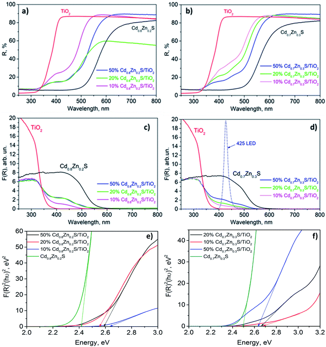
| Cd0.8Zn0.2S | — | 125 | 0.24 | 8 | 512 | 2.42 |
| 10% Cd0.8Zn0.2S/TiO2 | 10Cd0.8-P25 | 52 | 0.47 | 36 | 471 | 2.63 |
| 20% Cd0.8Zn0.2S/TiO2 | 20Cd0.8-P25 | 66 | 0.48 | 29 | 482 | 2.57 |
| 50% Cd0.8Zn0.2S/TiO2 | 50Cd0.8-P25 | 68 | 0.37 | 22 | 479 | 2.59 |
| Cd0.7Zn0.3S | — | 112 | 0.19 | 7 | 500 | 2.48 |
| 10% Cd0.7Zn0.3S/TiO2 | 10Cd0.7-P25 | 51 | 0.45 | 43 | 463 | 2.68 |
| 20% Cd0.7Zn0.3S/TiO2 | 20Cd0.7-P25 | 68 | 0.39 | 23 | 464 | 2.67 |
| 50% Cd0.7Zn0.3S/TiO2 | 50Cd0.7-P25 | 58 | 0.31 | 22 | 470 | 2.64 |
| TiO2 P25 (anatase/rutile) | P25 | 55 | 0.49 | 11 | 400 | 3.10 |
2.2. Sample characterization
The samples were characterized by various physicochemical techniques. The phase composition of the photocatalysts was examined using a D8 Advance diffractometer (Bruker) with Cu Kα radiation. The optical properties of the samples were studied by diffuse reflectance spectroscopy in the range of 250–800 nm. The spectra were recorded with a Shimadzu UV-2501 spectrophotometer with an ISR-240A diffuse reflectance unit. The specific surface areas (SBET), pore volumes, and average pore sizes of the photocatalysts were obtained from the low temperature N2 adsorption–desorption (N2 adsorption at 77 K) by using an ASAP 2400 apparatus.The structure and microstructure of the photocatalysts were studied by HRTEM using a ThemisZ electron microscope (Thermo Fisher Scientific, USA) operated at an accelerating voltage of 200 kV. The microscope was equipped with a corrector of spherical aberrations, which provided a maximum lattice resolution of 0.06 nm, and a SuperX spectrometer (TFS, USA). Images were recorded using a Ceta 16 CCD sensor (Thermo Fisher Scientific, USA). For electron microscopy studies, the samples were deposited on perforated carbon substrates attached to aluminum grids using an ultrasonic dispersant.
The XPS measurements were performed with a photoelectron spectrometer SPECS using Al Kα irradiation (hν = 1486.6 eV; 200 W). Binding energy (BE) scale was preliminarily calibrated by the position of the peaks of Au 4f7/2 (BE = 84.0 eV) and Cu 2p3/2 (BE = 932.67 eV) core levels. The binding energy of peaks was calibrated by the position of the C 1s peak at 284.8 eV (ref. 36) corresponding to the hydrocarbons presented on the samples surface. The spectra analysis and peak fitting were performed with XPS Peak 4.1 software. For the quantitative analysis, the integral intensities of the spectra were corrected by their respective atomic sensitivity factors.37
2.3. Photocatalytic hydrogen production
The catalytic properties of the prepared photocatalysts were studied in the hydrogen evolution from alkaline solution of triethanolamine. A typical procedure was described earlier.35 The experimental set-up for the photocatalytic activity measurements is described in detail in ESI (Fig. S1a†). A mixture containing 10 mL of triethanolamine (TEOA), 90 mL of 0.11 M NaOH, and 50 mg of the tested photocatalyst was placed to a reactor. Then the reactor was purged with argon for removing oxygen, after that the system was illuminated with 425-LED (56 mW cm−2, Fig. S1b†). The hydrogen concentration was measured by a gas chromatograph “Khromos GKh-1000” (Khromos, Russia). The apparent quantum efficiency (AQE) was calculated by the following formula:where W – reaction rate (μmol min−1), Nph – photon flux (μeinstein min−1). For all experiments Nph = 285 μeinstein min−1.
2.4. Photoelectrochemical experiments
Photoelectrochemical experiments were conducted using a two-electrode cell (see Fig. S1c and d†).38 The working electrode was FTO with the photocatalyst deposited by the drop-casting method described earlier.38 The counter electrode was Cu2S/brass, the electrolyte was a solution consisting of 1 M Na2Sn and 0.1 M NaCl. Photoelectrochemical characteristics were obtained with using a potentiostat–galvanostat P-45X (Russia). The current–time curves were registered at 0 V. The impedance data were recorded over a frequency range of 0.8 to 105 Hz with amplitude of 10 mV at 0.2 V. The light source was 425-LED (56 mW cm−2, Fig. S1b†).3. Results and discussion
3.1. Photocatalyst characterization
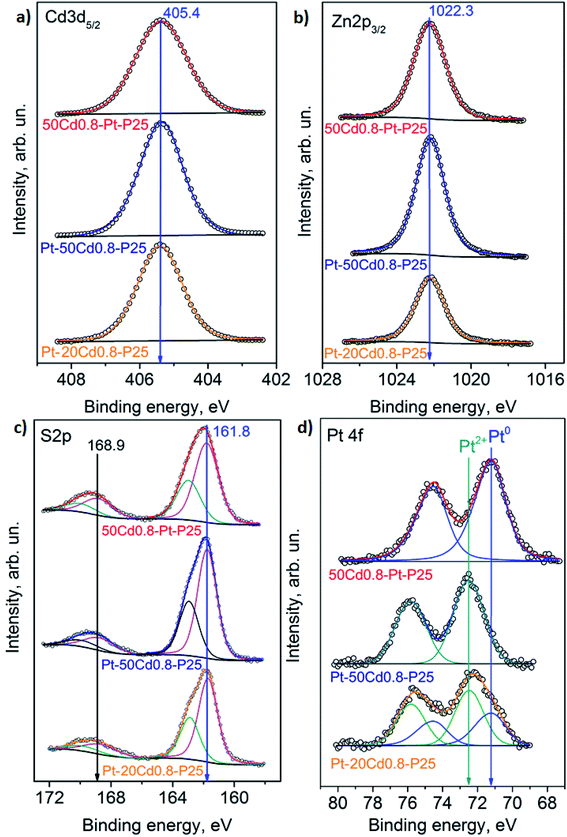
| Sample | [Pt0], % | [Pt2+], % | [S2−], % | [SOx2], % | [Cd]/[Cd + Zn] | [Pt]/[Cd + Zn] | [Pt]/[Ti] | [Cd + Zn]/[Ti] |
|---|---|---|---|---|---|---|---|---|
| Pt-20Cd0.8-P25 | 36 | 64 | 84 | 16 | 0.74 | 0.019 | 0.013 | 0.51 |
| 20Cd0.8-Pt-P25 | 100 | 0 | 89 | 11 | 0.73 | 0.033 | 0.017 | 0.57 |
| Pt-50Cd0.8-P25 | 0.0 | 1.0 | 85 | 15 | 0.65 | 0.028 | 0.019 | 0.70 |
| 50Cd0.8-Pt-P25 | 100 | 0 | 80 | 20 | 0.66 | 0.016 | 0.011 | 0.68 |
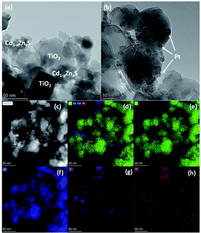 | ||
| Fig. 4 HRTEM images (a and b), HAADF-STEM (c) and elemental mapping of Ti/Zn/Cd/Pt (d), Ti (e), O (f), S (g), Pt (h) of photocatalyst Pt-20Cd0.8-P25. | ||
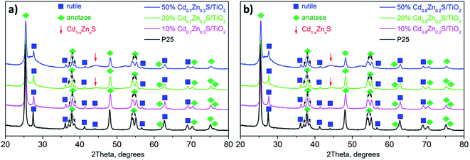
The TEM images and elemental mapping of the 20Cd0.8-Pt-P25 sample are summarized in Fig. 5. Images in Fig. 5a and b show the presence of titania with a particle size of 30–50 nm and clusters of disordered Cdl−xZnxS. One can see the platinum particles with a size of 2–4 nm (Fig. 5a and b). Also, element mapping shows that platinum is located both on titania particles and Cd1−xZnxS domains. To elucidate the location of platinum nanoparticles, we obtained the dark-field HAADF-STEM images of sample 20Cd0.8-Pt-P25 with a high resolution (Fig. 6a and b). One can see that platinum nanoparticles as to surround the titanium dioxide particles. Thus, according to the electron microscopy data, in sample 20Cd0.8-Pt-P25 the platinum clusters are located over titania and between two semiconductors and have smaller sizes than in sample Pt-20Cd0.8-P25. Thus, the electron microscopy data confirm that the Pt-20Cd0.8-P25 and Cd0.8-Pt-P25 photocatalysts differ only by platinum location and particle size, and have the same morphology of titania and cadmium and zinc sulfide solid solutions, and phase composition.
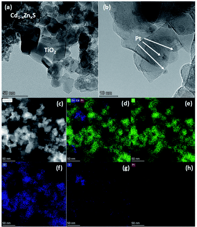 | ||
| Fig. 5 HRTEM images (a and b), HAADF-STEM (c) and elemental mapping of Ti/Zn/Cd/Pt (d), Ti (e), O (f), S (g), Pt (h) of photocatalyst 20Cd0.8-Pt-P25. | ||
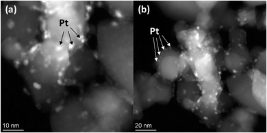 | ||
| Fig. 6 Dark field HAADF-STEM images of photocatalyst 20Cd0.8-Pt-P25 with a scale 10 nm (a) and 20 nm (b). | ||
To sum up, the photocatalyst characterization has shown that two synthetic techniques – deposition of platinum over Cd1−xZnxS (x = 0.2–0.3)/TiO2 P25 surface and deposition of Cd1−xZnxS (x = 0.2–0.3) over platinized Pt/TiO2 P25 – lead to the formation of photocatalysts with the same bulk structure; however, in the first case quite large platinum nanoparticles are located predominantly over Cd1−xZnxS surface, platinum exists in the oxidized Pt2+ state; in the latter case, small platinum nanoparticles are located over titania surface and all platinum is in metallic state.
3.2. Photocatalytic activity
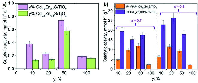
The activity of the synthesized photocatalysts was studied in the hydrogen evolution in alkaline solution of TEOA under visible light with a wavelength of 425 nm. It has been previously shown, that for CdS-based photocatalyst the use of TEOA as a sacrificial agent lead to the highest efficiency as compared to all other substrates. The results showed that amine might be strongly bound to the CdS surface and therefore effectively consume the holes as compared to alcohol and sugars.4 To facilitate the proton abstraction during the chain process of TEOA oxidation and therefore to prevent charge recombination the reaction was carried out in an 0.11 M NaOH aqueous solution.54 N-bis (2-hydroxyethyl) hydroxylamine and acetaldehyde are recognized as the main TEOA oxidation by-products.4 First, the photocatalysts without platinum were tested; the results of these experiments are listed in Fig. 7a. The rate of hydrogen evolution over titanium dioxide under visible light was equal to zero; single-phase Cd0.7Zn0.3S and Cd0.8Zn0.2S possessed noticeable activity. Fig. 7a shows that the samples containing 10 wt% and 20 wt% of Cd1−xZnxS exhibited the same photocatalytic activities, which were similar to those of Cd0.7Zn0.3S and Cd0.8Zn0.2S. However, as the content of Cd1−xZnxS increases to 50 wt%, the hydrogen production accelerates rapidly. Note that the activity of composite 50% Cd1−xZnxS/TiO2 P25 (x = 0.2–0.3) samples was 3.5-times higher that the activity of corresponding single phase solid solutions. Perhaps, this phenomenon may be caused by two reasons. Firstly, the enhancement of Cd1−xZnxS content in the photocatalyst increases the light absorption in the range where the LED emits, from 400 to 480 nm, which leads to the growth of the amount of the photoinduced electrons and holes and the photocatalytic activity. Secondly, it is well-known that heterojunctions between the solid solutions of CdS and ZnS and titania are realized55,56 and formed at the phase separation boundaries. High content of small Cd1−xZnxS particles provides a higher quantity of possible heterojunctions that enhances electron lifetime and favors the photocatalytic hydrogen production. One can see that the composite Cd1−xZnxS/TiO2 P25 samples containing Cd0.7Zn0.3S are more active than the photocatalysts with Cd0.8Zn0.2S solid solution. This trend was observed earlier for single phase solid solutions Cd1−xZnxS in hydrogen production from aqueous solutions of Na2S/Na2SO3.57–59 This phenomenon may be assigned to a higher conduction band position of Cd0.7Zn0.3S, which reflects the reduction ability of the semiconductor and favors the target reaction.To improve the photocatalytic properties of the composites, platinum was deposited by two methods. The first method includes Pt deposition on the surface of pre-synthesized y% Cdl−xZnxS/TiO2 (samples Pt-yCd0.8-P25), while in the second method the Cdl−xZnxS solid solutions were loaded on the 1% Pt/TiO2 (samples yCd0.8-Pt-P25). Also, platinum (1 wt%) was deposited on the surface of Cd0.7Zn0.3S and Cd0.8Zn0.2S. The catalytic activities of the studied photocatalysts are depicted in Fig. 7b. Analysis of the data in Fig. 7 allows conclusion that the depositon of platinum significantly (in some cases, more than an order of magnitude), improves the photocatalytic activity of the samples. The lowest hydrogen productivities, 2.9 and 2.6 mmol h−1 g−1, were possessed by the 1%Pt/Cd0.7Zn0.3S and 1%Pt/Cd0.8Zn0.2S single-phase samples, respectively. Composite platinized photocatalysts produced from 5 to 26 mmol h−1 g−1 of hydrogen (AQE = 1.4–7.7% at 425 nm) that exceed the latest published data (see Table 3![[thin space (1/6-em)]](https://www.rsc.org/images/entities/char_2009.gif) 60–74). The highest activity was possessed by photocatalyst 20Cd0.8-Pt-P25 (20% Cd0.8Zn0.2S/1% Pt/TiO2 P25). Fig. 7b also demonstrates that the yCd(1 − x)-Pt-P25 samples are more active than Pt-yCd(1 − x)-P25. The main reason of this observation is the different mechanisms by which electrons and holes migrate into the samples prepared according to two schemes.
60–74). The highest activity was possessed by photocatalyst 20Cd0.8-Pt-P25 (20% Cd0.8Zn0.2S/1% Pt/TiO2 P25). Fig. 7b also demonstrates that the yCd(1 − x)-Pt-P25 samples are more active than Pt-yCd(1 − x)-P25. The main reason of this observation is the different mechanisms by which electrons and holes migrate into the samples prepared according to two schemes.
| Sample | Sacrificial agents | Light source | Activity, mmol (H2) h−1 g−1 | Ref. | |
|---|---|---|---|---|---|
| 1 | Au/TiO2/gC3N4 | 1 vol% TEOA | 150 W ceramic–metal-halide Hg lamp | 0.4 | 11 |
| 2 | 3% Pt/2% Na2Fe2Ti6O16/g-C3N4 | 10 vol% TEOA | Xe lamp with 420 nm cut-off filter | 0.4 | 60 |
| 3 | 1% Pt/W18O49/g-C3N4 | 10 vol% TEOA | Xe lamp, λ > 400 nm | 0.9 | 61 |
| 4 | 1% C-dots/50% g-C3N4/TiO2 | 10 vol% TEOA | 350 W Xe arc lamp | 0.6 | 62 |
| 5 | 20% g-C3N4/TiO2 | 10 vol% TEOA | 250 W visible light source | 1.1 | 63 |
| 6 | C-quantum dots/TiO2/Pt | 0.33 M TEOA, pH = 9 | Xe lamp with 420 nm cut-off filter | 1.5 | 64 |
| 7 | Pt–g-C3N4–(Au/TiO2) | 25 vol% TEOA | Xe lamp with AM1.5 filter | 1.52 | 65 |
| 8 | 18%CdS/2%Pt/N–NaNbO3 | 10 vol% TEOA | Xe lamp with 420 nm cut-off filter | 1.8 | 66 |
| 9 | 40% CdS/4% PdAg/g-C3N4 | 10 vol% TEOA | Xe lamp with 420 nm cut-off filter | 3.1 | 67 |
| 10 | Pd0.22Pt0.78–TiO2/C | 5 vol% TEOA | Xe lamp with 420 nm cut-off filter | 2.9 | 68 |
| 11 | N–TiO2/g-C3N4@NixP | 10 vol% TEOA | Xe lamp with 350 nm cut-off filter | 5.4 | 69 |
| 12 | 0.25% Pt/Eosin Y-doped TiO2 | 0.25 M TEOA, pH = 7 | AM 1.5 G with 420 nm cut-off filter | 3.6 | 70 |
| 13 | 1% Pt/SrTiO3 | 10 vol% TEOA, pH = 7, 0.1 g L−1 eosin Y | Xe lamp with 420 nm cut-off filter | 6.6 | 71 |
| 14 | 2.5% PtNix/g-C3N4 | 10 vol% TEOA | Xe lamp | 8.5 | 72 |
| 15 | 0.33% Pt/TiO2/P-doped g-C3N4 | 10 vol% TEOA | Xe lamp with 420 nm cut-off filter | 11.6 | 73 |
| 16 | Cu/TiO2 | 17 vol% TEOA, pH = 6 | Xe lamp with 420 nm cut-off filter | 5.9 | 74 |
| 17 | 1%Pt/20% Cd0.8Zn0.2S/TiO2 | 10 vol% TEOA, 0.1 M NaOH | 425-LED | 11.5 | This work |
| 18 | 20% Cd0.8Zn0.2S/1%Pt/TiO2 | 26.4 |
According to the difference in the positions of Cdl−xZnxS and TiO2 bands in the ternary system, the following types of heterojunctions can take place: type II heterojunctions, Z-scheme, and S-scheme.33 In the case of platinized photocatalyst, the Z-scheme heterojunctions are hardly possible owing to the formation of a Schottky barrier between Pt and Cdl−xZnxS or TiO2.33 Also, the type II heterojunctions between the semiconductors may be realized.26,27 In this case, under light irradiation electrons and holes are generated in the Cd1−xZnxS conduction band (CB) and valence band (VB), respectively. Since the position of TiO2 CB is lower than that of Cd0.8Zn0.2S, photoinduced electrons can migrate to CB of titania, whereas photogenerated holes remain in VB of sulfide solid solution. Thus, in this case, electrons are collected in CB of TiO2, and holes – in VB of Cdl−xZnxS. On the contrary, when implementing S-scheme, photogenerated electrons remain in CB of Cdl−xZnxS, and holes – in VB of titania providing high reducing and oxidizing ability, respectively.32–34 Platinum is an effective co-catalyst for hydrogen production. Thus, in the case of the S-scheme heterojunctions, it is advantageous for platinum to be located on the sulfide surface, and in the case of the type II heterojunctions – over titanium dioxide. In the present study, samples yCd(1 − x)-Pt-P25 with platinum deposited on titania surface are much more active than samples Pt-yCd(1 − x)-P25 with platinum located over Cdl−xZnxS nanoparticles that allows suggestion that exactly the type II heterojunctions occur in the system. Besides, Fig. 2d clearly shows that titanium dioxide does not absorb irradiation from the LED source used in the experiments, whereas Z-scheme and S-scheme assume the light absorption by both semiconductors.
Fig. 8 shows probable scheme of heterojunctions for Pt-yCd(1 − x)-P25 and yCd(1 − x)-Pt-P25 photocatalysts. As described above, the photoinduced electrons can migrate to the CB of titanium dioxide, whereas photogenerated holes remain in the VB of the sulfide solid solution. Also, for Pt-yCd(1 − x)-P25 (Fig. 8a), photogenerated electrons can move to platinum deposited on the surface of Cd1−xZnxS; in this case both electrons and holes remain on the surface of Cd1−xZnxS. The activity of composite samples Pt-y-Cd(1 − x)-P25 (y = 20–50%; x = 0.2–0.3) reaches the level of ∼10 mmol h−1 g−1, and at least 3.5–4 times exceeds the activity of photocatalysts 1%Pt/Cd0.7Zn0.3S and 1%Pt/Cd0.8Zn0.2S. Thus, it turns out that the type II heterojunctions provide efficient spatial separation of charges and improve the catalyst activity in the hydrogen evolution. However, the CB position of TiO2 vs. NHE is not negative enough (ca.−0.1 V), with a low reducing ability of electrons; moreover, judging by the TEM data, platinum is deposited mainly on sulfide nanoparticles, and reduction proceeds over pristine titania. Therefore, the activity in the hydrogen production is not so high in comparison to the photocatalysts, synthesized according to the second method.
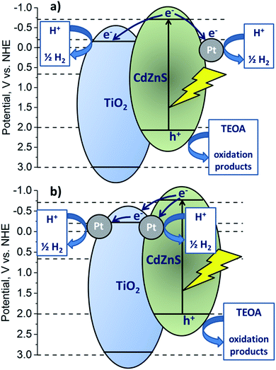 | ||
| Fig. 8 Scheme of the possible type II heterojunctions realized in the case of the Pt-yCd(1 − x)-P25 (a) and yCd(1 − x)- Pt-P25 (b) photocatalyst. | ||
Fig. 7 shows that photocatalysts yCd(1 − x)-Pt-P25 (y = 10–20%; x = 0.2) possess the highest activity, 23–26 mmol h−1 g−1 of hydrogen, more than twice exceeding that of samples with the same bulk structure, Pt-yCd(1 − x)-P25 (y = 10–20%; x = 0.2). In the yCd(1 − x)-Pt-P25 photocatalysts, platinum particles are located over titania nanoparticles. In this case, photogenerated electrons first migrate to CB of TiO2 and then to platinum particles, deposited over the surface of titania; photogenerated holes remain in the Cd1−xZnxS VB (Fig. 8b). High activity of the yCd(1 − x)-Pt-P25 (y = 10–20%; x = 0.2) samples confirms that the transfer of electrons in this direction has a positive effect on the separation of photogenerated charges. Pt particles at the interface between sulfide and titanium dioxide can also be effective co-catalysts for the evolution of hydrogen, although their number is less than the number of Pt particles on the TiO2 surface. Another reason for the high activity of yCd(1 − x)-Pt-P25 is that it contains Pt only in the metallic state, while in Pt-yCd(1 − x)-P25 platinum occurs both as Pt0 and Pt2+. The metallic platinum accelerates the photocatalytic reaction to a greater extent than the oxidized one.54 Certainly, it is difficult to provide unambiguous arguments in favor of a particular heterojunction mechanism, but our experiments clearly show that the deposition of platinum on titanium dioxide, followed by deposition of Cd1−xZnxS, leads to the production of highly active photocatalysts. Indeed, the activity of the 20% Cd0.8Zn0.2S/1% Pt/TiO2 P25 photocatalyst in H2 evolution by an order of magnitude exceeds that of a platinized solid solution 1%Pt/Cd0.8Zn0.2S. At the same time, our preliminary studies of these systems in the reduction of CO2 showed that the deposition of platinum on the particles of sulfide solid solutions was preferable.20
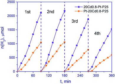
Stability is one of the most important characteristics of a photocatalyst. Thus, stability tests were carried out with samples Pt-20Cd0.8-P25 and 20Cd0.8-Pt-P25 (Fig. 9). After four 1.5 h runs, the hydrogen production rate was 57 and 72% of the initial rate for photocatalysts Pt-20Cd0.8-P25 and 20Cd0.8-Pt-P25, respectively. That is, the sample of the second type, 20Cd0.8-Pt-P25, possesses the higher activity and stability, most likely due to the improved charge separation. Unfortunately, it is very difficult to obtain highly stable composite sulfide photocatalysts, because photogenerated holes oxidize sulfide solid solutions.53
3.3. Photoelectrochemical tests
The photoelectrochemical properties of 1% Pt/TiO2, 20% Cd0.8Zn0.2S/TiO2, and 20Cd0.8-Pt-P25 were studied. Fig. 10a demonstrates that composite photocatalyst 20Cd0.8-Pt-P25 prepared by the second route provides a higher photocurrent generation than both platinized titania and 20% Cd0.8Zn0.2S/TiO2. The main reason of this fact is high photogenerated charge separation associated with the type II heterojunctions which is realized under visible light. It is seen also that photocurrent density obtained over 20Cd0.8-Pt-P25 decreases during first two on–off cycles, and remains constant afterwards. In opposite, the photocurrent densities recorded over 1% Pt/TiO2 and 20% Cd0.8Zn0.2S/TiO2 continuously decline due to photocorrosion processes, such as self-oxidation of the CdS and ZnS solid solutions. The ternary composite photocatalyst is photoelectrochemically active and stable. The samples were investigated by the impedance spectroscopy and electron lifetimes were calculated.38 The electron lifetimes of 1% Pt/TiO2, 20% Cd0.8Zn0.2S/TiO2, 20Cd0.8-Pt-P25 were 2.7 ms, 5.8 ms, and 8.9 ms, respectively. One can conclude that the higher electron lifetime values favor both the photocatalytic hydrogen production and photocurrent generation.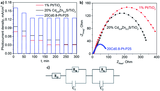 | ||
| Fig. 10 The I–t curves (a) and Nyquist plots (b) of 1% Pt/TiO2, 20% Cd0.8Zn0.2S/TiO2, and 20Cd0.8-Pt-P25; electrical equivalent-circuit model used for the impedance data approximation (c). | ||
Fig. 10b shows the Nyquist plots obtained over the tested photoelectrodes. The main trend observed is that low values of impedance semicircle radii led to enhanced photocurrent density. Additionally, the impedance data was approximated by the equivalent-circuit model suggested earlier.75 The model consists of the series resistance RD in parallel with two resistance–capacitance loops (RW–C1, RK–C2) (see Fig. 10c). The series resistance RD includes all the contact and material resistances, such as resistance of the FTO surface and electrolyte solution. RW and C1 were attributed to the charge-transfer resistance and double-layer capacity for the processes at the photoelectrode/electrolyte interface, whereas RK and C2 described the electrochemical processes at the counter electrode/electrolyte interface. It was shown that series resistance RD values did not exceed 10 Ohm that was typical of the electrolyte resistance. Parameters RW and RK decreased in the consequence 1% Pt/TiO2/FTO > 20% Cd0.8Zn0.2S/TiO2/FTO > 20Cd0.8-Pt-P25. It should be noted that photocurrent density and electron lifetime grew in the same consequence. The ternary composite photoelectrode demonstrated low resistivity and high electron lifetime. It means that the charge separation in the space was more efficient for the 20Cd0.8-Pt-P25/FTO sample as proved by the electrochemical methods.
4. Conclusions
Ternary composite samples consisting of Cd1−xZnxS, titania P25 and platinum were synthesized using a different sequence of metal deposition. In the first case, platinum (1 wt%) was deposited on the surface of synthesized Cd1−xZnxS (x = 0.2–0.3)/TiO2 P25; in the second case Cd1−xZnxS (x = 0.7–0.8) was deposited on the surface platinized titania. This approach made it possible to obtain photocatalysts with the same bulk structure while the properties of deposited platinum were rather different. According to the data of physicochemical studies, including HRTEM with mapping, in photocatalysts synthesized by the first method (1% Pt/Cdl−xZnxS/TiO2) relatively large platinum particles are located predominantly on the Cd1−xZnxS surface, Pt can exist both in metallic Pt0 and oxidized Pt2+ states; photocatalysts synthesized by the second method (Cdl−xZnxS/1% Pt/TiO2) contain small platinum particles which are located on the TiO2 surface, the whole platinum is in metallic state.The photocatalytic properties were tested in hydrogen production from alkaline aqueous solution of TEOA under visible light irradiation with a wavelength of 425 nm. It was found that the y% Cdl−xZnxS/1% Pt/TiO2 photocatalysts demonstrated much higher photocatalytic activity than y% 1% Pt/Cdl−xZnxS/TiO2 samples. Thus, the arrangement of platinum nanoparticles precisely on titanium dioxide surface in a composite photocatalyst makes it possible to achieve efficient charge separation according to type II heterojunctions and, accordingly, a high rate of hydrogen formation. Also, the deposition of a solid solution of sulfides on the surface of platinized titania makes it possible to “seal” the platinum particles and keep them in a metallic state, whereas deposition of platinum over Cd1−xZnxS/TiO2 composite leads to formation of mixed Pt/PtOx co-catalyst.
The highest photocatalytic activity was observed for 20% Cd0.8Zn0.2S/1% Pt/TiO2 which provided hydrogen production of 26 mmol g−1 h−1 (apparent quantum efficiency was 7.7%) that exceeds the latest published values. This photocatalyst possessed high photoelectrochemical stability. It should be noted that, despite the apparent simplicity, the determination of the preferred location of platinum particles in the TiO2–Cd1−xZnxS systems was carried out for the first time.
Authors contributions
A. V. Zhurenok: conceptualization, validation, visualization, writing—original draft preparation; D. V. Markovskaya: investigation, data curation, visualization, writing—original draft preparation; E. Yu. Gerasimov: investigation, visualization; S. V. Cherepanova: data curation, formal analysis; A. V. Bukhtiyarov: data curation, formal analysis; E. A. Kozlova: writing—original draft preparation, supervision, project administration, funding acquisition. All authors have read and agreed to the published version of the manuscript.Conflicts of interest
The authors declare that they have no known competing financial interests or personal relationships that could have appeared to influence the work reported in this paper.Acknowledgements
This work was supported by the Ministry of Science and Higher Education of the Russian Federation within the governmental order for Boreskov Institute of Catalysis (project AAAA-A21-121011390009-1) and also was partially supported by the Russian Foundation for Basic Research (project no. 20-33-70086). The authors are grateful to T. V. Larina for DRS analysis. The studies were conducted using the equipment of the Center of Collective Use “National Center of Catalyst Research”.References
- E. A. Kozlova and V. N. Parmon, Heterogeneous semiconductor photocatalysts for hydrogen production from aqueous solutions of electron donors, Russ. Chem. Rev., 2017, 86, 870–906, DOI:10.1070/rcr4739.
- C. W. Huang, B. S. Nguyen, J. C. S. Wu and V. H. Nguyen, A current perspective for photocatalysis towards the hydrogen production from biomass-derived organic substances and water, Int. J. Hydrogen Energy, 2020, 45, 18144–18159, DOI:10.1016/j.ijhydene.2019.08.121.
- S. Bagheri and N. Muhd Julkapli, Nano-diamond based photocatalysis for solar hydrogen production, Int. J. Hydrogen Energy, 2020, 45, 31538–31554, DOI:10.1016/j.ijhydene.2020.08.193.
- V. Kumaravel, M. D. Imam, A. Badreldin, R. K. Chava, J. Y. Do and M. Kang, et al., Photocatalytic hydrogen production: Role of sacrificial reagents on the activity of oxide, carbon, and sulfide catalysts, Catalysts, 2019, 9, 276, DOI:10.3390/catal9030276.
- W. Jones, D. J. Martin, A. Caravaca, A. M. Beale, M. Bowker and T. Maschmeyer, et al., A comparison of photocatalytic reforming reactions of methanol and triethanolamine with Pd supported on titania and graphitic carbon nitride, Appl. Catal., B, 2019, 240, 373–379, DOI:10.1016/j.apcatb.2017.01.042.
- U. Pal, S. Ghosh and D. Chatterjee, Effect of sacrificial electron donors on hydrogen generation over visible light-irradiated nonmetal-doped TiO2 photocatalysts, Transition Met. Chem., 2012, 37, 93–96, DOI:10.1007/s11243-011-9562-3.
- R. Malik, V. K. Tomer, N. Joshi, T. Dankwort, L. Lin and L. Kienle, Au-TiO2-Loaded Cubic g-C3N4 Nanohybrids for Photocatalytic and Volatile Organic Amine Sensing Applications, ACS Appl. Mater. Interfaces, 2018, 10, 38087–38097, DOI:10.1021/acsami.8b08091.
- Y. Chen, B. Lin, H. Wang, Y. Yang, H. Zhu and W. Yu, et al., Surface modification of g-C3N4 by hydrazine: Simple way for noble-metal free hydrogen evolution catalysts, Chem. Eng. J., 2016, 286, 339–346, DOI:10.1016/j.cej.2015.10.080.
- J. Ding, X. Sun, Q. Wang, L. D. Sheng, X. Li and X. Li, et al., Plasma synthesis of Pt/g-C3N4 photocatalysts with enhanced photocatalytic hydrogen generation, J. Alloys Compd., 2021, 873, 159871, DOI:10.1016/j.jallcom.2021.159871.
- Z. Guo, Y. Zhao, H. Shi, X. Yuan, W. Zhen and L. He, et al., MoSe2/g-C3N4 heterojunction coupled with Pt nanoparticles for enhanced photocatalytic hydrogen evolution, J. Phys. Chem. Solids, 2021, 156, 110137, DOI:10.1016/j.jpcs.2021.110137.
- P. Jiménez-Calvo, V. Caps, M. N. Ghazzal, C. Colbeau-Justin and V. Keller, Au/TiO2(P25)-gC3N4 composites with low gC3N4 content enhance TiO2 sensitization for remarkable H2 production from water under visible-light irradiation, Nano Energy, 2020, 75, 104888, DOI:10.1016/j.nanoen.2020.104888.
- B. Lv, X. Feng, L. Lu, L. H. Xia, Y. Yang and X. Wang, et al., Facile synthesis of g-C3N4/TiO2/CQDs/Au Z-scheme heterojunction composites for solar-driven efficient photocatalytic hydrogen, Diamond Relat. Mater., 2021, 111, 108212, DOI:10.1016/j.diamond.2020.108212.
- Y. Yang, C. Lu, J. Ren, X. Li, Y. Ma and W. Huang, et al., Enhanced photocatalytic hydrogen evolution over TiO2/g-C3N4 2D heterojunction coupled with plasmon Ag nanoparticles, Ceram. Int., 2020, 46, 5725–5732, DOI:10.1016/j.ceramint.2019.11.021.
- H. Zhu, X. Yang, M. Zhang, Q. Li and J. Yang, Construction of 2D/2D TiO2/g-C3N4 nanosheet heterostructures with improved photocatalytic activity, Mater. Res. Bull., 2020, 125, 110765, DOI:10.1016/j.materresbull.2019.110765.
- J. Wang, G. Wang, X. Wang, Y. Wu, Y. Su and H. Tang, 3D/2D direct Z-scheme heterojunctions of hierarchical TiO2 microflowers/g-C3N4 nanosheets with enhanced charge carrier separation for photocatalytic H2 evolution, Carbon, 2019, 149, 618–626, DOI:10.1016/j.carbon.2019.04.088.
- A. L. Linsebigler, G. Lu and J. T. Yates Jr, Photocatalysis on TiO2 Surfaces: Principles, Mechanisms, and Selected Results, Chem. Rev., 2002, 95, 735–758, DOI:10.1021/CR00035A013.
- M. R. Hoffmann, S. T. Martin, W. Choi and D. W. Bahnemann, Environmental Applications of Semiconductor Photocatalysis, Chem. Rev., 2002, 95, 69–96, DOI:10.1021/CR00033A004.
- J. M. Herrmann, Heterogeneous photocatalysis: Fundamentals and applications to the removal of various types of aqueous pollutants, Catal. Today, 1999, 53, 115–129, DOI:10.1016/S0920-5861(99)00107-8.
- A. Corma and H. Garcia, Photocatalytic reduction of CO2 for fuel production: Possibilities and challenges, J. Catal., 2013, 308, 168–175, DOI:10.1016/J.JCAT.2013.06.008.
- D. V. Markovskaya, M. N. Lyulyukin, A. V. Zhurenok and E. A. Kozlova, New composite photocatalysts based on solid solutions of cadmium sulfide and zinc sulfide, titania, and platinum for photocatalytic reduction of carbon dioxide with water vapors under visible light irradiation, Kinet. Catal., 2021, 62, 437–445, DOI:10.31857/S0453881121040109.
- A. A. Rempel, Y. V. Kuznetsova, I. B. Dorosheva, A. A. Valeeva, I. A. Weinstein and E. A. Kozlova, et al., High Photocatalytic Activity Under Visible Light of Sandwich Structures Based on Anodic TiO2/CdS Nanoparticles/Sol–Gel TiO2, Top. Catal., 2020, 63, 130–138, DOI:10.1007/S11244-020-01226-X.
- H. Zhao, C. F. Li, L. Y. Liu, B. Palma, Z. Y. Hu and S. Renneckar, et al., n-p Heterojunction of TiO2-NiO core-shell structure for efficient hydrogen generation and lignin photoreforming, J. Colloid Interface Sci., 2021, 585, 694–704, DOI:10.1016/J.JCIS.2020.10.049.
- R. Fiorenza, S. A. Balsamo, M. Condorelli, L. D'Urso, G. Compagnini and S. Scirè, Solar photocatalytic H2 production over CeO2-based catalysts: Influence of chemical and structural modifications, Catal. Today, 2021, 380, 187–198, DOI:10.1016/J.CATTOD.2021.02.003.
- L. Luo, T. Zhang, X. Zhang, R. Yun, Y. Lin and B. Zhang, et al., Enhanced Hydrogen Production from Ethanol Photoreforming by Site-Specific Deposition of Au on Cu2O/TiO2 p–n Junction, Catalysts, 2020, 10, 539, DOI:10.3390/CATAL10050539.
- J. S. Jang, S. H. Choi, H. G. Kim and J. S. Lee, Location and State of Pt in Platinized CdS/TiO2 Photocatalysts for Hydrogen Production from Water under Visible Light, J. Phys. Chem. C, 2008, 112, 17200–17205, DOI:10.1021/JP804699C.
- V. M. Daskalaki, M. Antoniadou, G. L. Puma, D. I. Kondarides and P. Lianos, Solar Light-Responsive Pt/CdS/TiO2 Photocatalysts for Hydrogen Production and Simultaneous Degradation of Inorganic or Organic Sacrificial Agents in Wastewater, Environ. Sci. Technol., 2010, 44, 7200–7205, DOI:10.1021/ES9038962.
- H. Park, W. Choi and M. R. Hoffmann, Effects of the preparation method of the ternary CdS/TiO2/Pt hybrid photocatalysts on visible light-induced hydrogen production, J. Mater. Chem., 2008, 18, 2379–2385, 10.1039/B718759A.
- M. De Oliveira Melo and L. A. Silva, Visible light-induced hydrogen production from glycerol aqueous solution on hybrid Pt–CdS–TiO2 photocatalysts, J. Photochem. Photobiol., A, 2011, 226, 36–41, DOI:10.1016/J.JPHOTOCHEM.2011.10.012.
- H. Yu, Y. Huang, D. Gao, P. Wang and H. Tang, Improved H2-generation performance of Pt/CdS photocatalyst by a dual-function TiO2 mediator for effective electron transfer and hole blocking, Ceram. Int., 2019, 45, 9807–9813, DOI:10.1016/J.CERAMINT.2019.02.018.
- H. Nagakawa and M. Nagata, Elucidating the Factors Affecting Hydrogen Production Activity Using a CdS/TiO2 Type-II Composite Photocatalyst, ACS Omega, 2021, 6, 4395–4400, DOI:10.1021/ACSOMEGA.0C05749.
- M. Solakidou, A. Giannakas, Y. Georgiou, N. Boukos, M. Louloudi and Y. Deligiannakis, Efficient photocatalytic water-splitting performance by ternary CdS/Pt-N-TiO2 and CdS/Pt-N,F-TiO2: Interplay between CdS photo corrosion and TiO2-dopping, Appl. Catal., B, 2019, 254, 194–205, DOI:10.1016/J.APCATB.2019.04.091.
- Q. Xu, L. Zhang, B. Cheng, J. Fan and J. Yu, S-Scheme heterojunction photocatalyst, Chem, 2020, 6, 1543–1559, DOI:10.1016/J.CHEMPR.2020.06.010.
- H. Ge, F. Xu, B. Cheng, J. Yu and W. Ho, S-Scheme Heterojunction TiO2/CdS Nanocomposite Nanofiber as H2-Production Photocatalyst, ChemCatChem, 2019, 11, 6301–6309, DOI:10.1002/CCTC.201901486.
- Z. Wang, Y. Chen, L. Zhang, B. Cheng, J. Yu and J. Fan, Step-scheme CdS/TiO2 nanocomposite hollow microsphere with enhanced photocatalytic CO2 reduction activity, J. Mater. Sci. Technol., 2020, 56, 143–150, DOI:10.1016/J.JMST.2020.02.062.
- A. V. Zhurenok, T. V. Larina, D. V. Markovskaya, S. V. Cherepanova, E. A. Mel'gunova and E. A. Kozlova, Synthesis of graphitic carbon nitride-based photocatalysts for hydrogen evolution under visible light, Mendeleev Commun., 2021, 31, 157–159, DOI:10.1016/j.mencom.2021.03.004.
- J. F. Moulder, W. F. Stickle, P. E. Sobol and K. D. Bomben, Handbook of X-Ray Photoelectron Spectroscopy, PerkinElmer Corp., Eden Prairie, MN, 1992, p. 261 Search PubMed.
- J. H. Scofield, Hartree-Slater subshell photoionization cross-sections at 1254 and 1487 eV, J. Electron Spectrosc. Relat. Phenom., 1976, 8, 129–137 CrossRef CAS.
- D. V. Markovskaya, E. N. Gribov, E. A. Kozlova, D. V. Kozlov and V. N. Parmon, Modification of sulfide-based photocatalyst with zinc- and nickel containing compounds: correlation between photocatalytic activity and photoelectrochemical parameters, Renewable Energy, 2020, 151, 286–294, DOI:10.1016/j.renene.2019.11.030.
- S. V. Cherepanova, X-ray scattering on one-dimensional disordered structures, J. Struct. Chem., 2012, 53, 109–132, DOI:10.1134/S0022476612070116.
- E. A. Kozlova, A. Y. Kurenkova, V. S. Semeykina, E. V. Parkhomchuk, S. V. Cherepanova and E. Y. Gerasimov, et al., Effect of Titania Regular Macroporosity on the Photocatalytic Hydrogen Evolution on Cd1−xZnxS/TiO2 Catalysts under Visible Light, ChemCatChem, 2015, 7, 4108–4117, DOI:10.1002/CCTC.201500897.
- O. Carp, C. L. Huisman and A. Reller, Photoinduced reactivity of titanium dioxide, Prog. Solid State Chem., 2004, 32, 33–177, DOI:10.1016/j.progsolidstchem.2004.08.001.
- L. Ding, S. Yang, Z. Liang, X. Qian, X. Chen, H. Cui and J. Tian, TiO2 nanobelts with anatase/rutile heterophase junctions for highly efficient photocatalytic overall water splitting, J. Colloid Interface Sci., 2020, 567, 181–189, DOI:10.1016/j.jcis.2020.02.014.
- H. Krysova, M. Zlamalova, H. Tarabkova, J. Jirkovsky, O. Frank, M. Kohout and L. Kavan, Rutile TiO2 thin electrodes with excellent blocking function and optical transparency, Electrochim. Acta, 2019, 321, 134685, DOI:10.1016/j.electacta.2019.134685.
- J. C. Wu, J. Zheng, C. L. Zacherl, P. Wu, Z. K. Liu and R. Xu, Hybrid functionals study of band bowing, band edges and electronic structures of Cd1−xZnxS solid solution, J. Phys. Chem. C, 2011, 115, 19741–19748, DOI:10.1021/jp204799q.
- M. Li, J. Jiang and L. Guo, Synthesis, characterization, and photoelectrochemical study of Cd1−xZnxS solid solution thin films deposited by spray pyrolysis for water splitting, Int. J. Hydrogen Energy, 2010, 35, 7036–7042, DOI:10.1016/j.ijhydene.2009.12.090.
- K. Zhang, D. Jing, C. Xing and L. Guo, Significantly improved photocatalytic hydrogen production activity over Cdl−xZnxS photocatalysts prepared by a novel thermal sulfuration method, Int. J. Hydrogen Energy, 2007, 32, 4685–4691, DOI:10.1016/j.ijhydene.2007.08.022.
- E. A. Kozlova, M. N. Lyulyukin, D. V. Markovskaya, A. V. Bukhtiyarov, I. P. Prosvirin, S. V. Cherepanova and D. V. Kozlov, Photocatalytic CO2 reduction over Ni-modified Cd1−xZnxS-based photocatalysts: effect of phase composition of photocatalyst and reaction media on reduction rate and product distribution, Top. Catal., 2020, 63, 121–129, DOI:10.1007/s11244-020-01233-y.
- C. Li, X. Yang, B. Yang, Y. Yan and Y. Qian, Growth of microtubular complexes as precursors to synthesize nanocrystalline ZnS and CdS, J. Cryst. Growth, 2006, 291, 45–51, DOI:10.1016/j.jcrysgro.2006.02.050.
- D. V. Markovskaya, E. A. Kozlova, E. Y. Gerasimov, A. V. Bukhtiyarov and D. V. Kozlov, New photocatalysts based on Cd0.3Zn0.7S and Ni(OH)2 for hydrogen production from ethanol aqueous solutions under visible light, Appl. Catal., A, 2018, 563, 170–176, DOI:10.1016/j.apcata.2018.07.002.
- A. F. H. Sanders, A. M. De Jong, V. H. J. De Beer, J. A. R. Van Veen and J. W. Niemantsverdriet, Formation of cobalt-molybdenum sulfides in hydrotreating catalysts: A surface science approach, Appl. Surf. Sci., 1999, 144–145, 380–384, DOI:10.1016/S0169-4332(98)00831-9.
- J. R. Croy, S. Mostafa, L. Hickman, H. Heinrich and B. R. Cuenya, Bimetallic Pt-Metal catalysts for the decomposition of methanol: Effect of secondary metal on the oxidation state, activity, and selectivity of Pt, Appl. Catal., A, 2008, 350, 207–216, DOI:10.1016/j.apcata.2008.08.013.
- I. A. Chetyrin, A. V. Bukhtiyarov, I. P. Prosvirin, A. K. Khudorozhkov and V. I. Bukhtiyarov, In Situ XPS and MS Study of Methane Oxidation on the Pd–Pt/Al2O3 Catalysts, Top. Catal., 2020, 63, 66–74, DOI:10.1007/s11244-019-01217-7.
- A. Y. Kurenkova, D. V. Markovskaya, E. Y. Gerasimov, I. P. Prosvirin, S. V. Cherepanova and E. A. Kozlova, New insights into the mechanism of photocatalytic hydrogen evolution from aqueous solutions of saccharides over CdS-based photocatalysts under visible light, Int. J. Hydrogen Energy, 2020, 45, 30165–30177, DOI:10.1016/j.ijhydene.2020.08.133.
- Y. Pellegrin and F. Odobel, Sacrificial electron donor reagents for solar fuel production, C. R. Chim., 2017, 20, 283–295, DOI:10.1016/J.CRCI.2015.11.026.
- G. Yang, Q. Zhang, W. Chang and W. Yan, Fabrication of Cd1−xZnxS/TiO2 heterostructures with enhanced photocatalytic activity, J. Alloys Compd., 2013, 580, 29–36, DOI:10.1016/j.jallcom.2013.05.083.
- Q. Yu, J. Xu, W. Wang and C. Lu, Facile preparation and improved photocatalytic H2-production of Pt-decorated CdS/TiO2 nanorods, Mater. Res. Bull., 2014, 51, 40–43, DOI:10.1016/j.materresbull.2013.12.002.
- D. V. Markovskaya, A. V. Zhurenok, S. V. Cherepanova and E. A. Kozlova, Solid solutions of CdS and ZnS: Comparing photocatalytic activity and photocurrent generation, Appl. Surf. Sci. Adv., 2021, 4, 100076, DOI:10.1016/j.apsadv.2021.100076.
- M. Liu, L. Wang, G. Lu, X. Yao and L. Guo, Twins in Cd1−xZnxS solid solution: Highly efficient photocatalyst for hydrogen generation from water, Energy Environ. Sci., 2011, 4, 1372–1378, 10.1039/c0ee00604a.
- H. Du, K. Liang, C. Z. Yuan, H. L. Guo, X. Zhou and Y. F. Jiang, et al., Bare Cd1−xZnxS ZB/WZ Heterophase Nanojunctions for Visible Light Photocatalytic Hydrogen Production with High Efficiency, ACS Appl. Mater. Interfaces, 2016, 8, 24550–24558, DOI:10.1021/acsami.6b06182.
- Z. Q. Guo, Q. W. Chen and J. P. Zhou, Na2Fe2Ti6O16 as a hybrid co-catalyst on g-C3N4 to enhance the photocatalytic hydrogen evolution under visible light illumination, Appl. Surf. Sci., 2020, 509, 145357, DOI:10.1016/J.APSUSC.2020.145357.
- A. Li, Z. Peng and X. Fu, Exfoliated, mesoporous W18O49/g-C3N4 composites for efficient photocatalytic H2 evolution, Solid State Sci., 2020, 106, 106298, DOI:10.1016/j.solidstatesciences.2020.106298.
- Y. Li, X. Feng, Z. Lu, H. Yin, F. Liu and Q. Xiang, Enhanced photocatalytic H2-production activity of C-dots modified g-C3N4/TiO2 nanosheets composites, J. Colloid Interface Sci., 2018, 513, 866–876, DOI:10.1016/j.jcis.2017.12.002.
- M. A. Alcudia-Ramos, M. O. Fuentez-Torres, F. Ortiz-Chi, C. G. Espinosa-González, N. Hernández-Como and D. S. García-Zaleta, et al., Fabrication of g-C3N4/TiO2 heterojunction composite for enhanced photocatalytic hydrogen production, Ceram. Int., 2020, 46, 38–45, DOI:10.1016/j.ceramint.2019.08.228.
- M. T. Genc, G. Yanalak, G. Arslan and I. H. Patir, Green preparation of Carbon Quantum dots using Gingko biloba to sensitize TiO2 for the photohydrogen production, Mater. Sci. Semicond. Process., 2020, 109, 104945, DOI:10.1016/j.mssp.2020.104945.
- P. Devaraji and C. S. Gopinath, Pt – g-C3N4 – (Au/TiO2): Electronically integrated nanocomposite for solar hydrogen generation, Int. J. Hydrogen Energy, 2018, 43, 601–613, DOI:10.1016/j.ijhydene.2017.11.057.
- F. Yang, Q. Zhang, J. Zhang, L. Zhang, M. Cao and W. L. Dai, Embedding Pt nanoparticles at the interface of CdS/NaNbO3 nanorods heterojunction with bridge design for superior Z-Scheme photocatalytic hydrogen evolution, Appl. Catal., B, 2020, 278, 119290, DOI:10.1016/j.apcatb.2020.119290.
- J. Gao, F. Zhang, H. Xue, L. Zhang, Y. Peng and X. L. Li, et al., In-situ synthesis of novel ternary CdS/PdAg/g-C3N4 hybrid photocatalyst with significantly enhanced hydrogen production activity and catalytic mechanism exploration, Appl. Catal., B, 2021, 281, 119509, DOI:10.1016/J.APCATB.2020.119509.
- A. G. M. da Silva, C. G. Fernandes, Z. D. Hood, R. Peng, Z. Wu and A. H. B. Dourado, et al., PdPt-TiO2 nanowires: correlating composition, electronic effects and O-vacancies with activities towards water splitting and oxygen reduction, Appl. Catal., B, 2020, 277, 119177, DOI:10.1016/j.apcatb.2020.119177.
- M. Wu, J. Zhang, C. Liu, Y. Gong, R. Wang and B. He, et al., Rational Design and Fabrication of Noble-metal-free NixP Cocatalyst Embedded 3D N-TiO2/g-C3N4 Heterojunctions with Enhanced Photocatalytic Hydrogen Evolution, ChemCatChem, 2018, 10, 3069–3077, DOI:10.1002/CCTC.201800197.
- P. Chowdhury, H. Gomaa and A. K. Ray, Sacrificial hydrogen generation from aqueous triethanolamine with Eosin Y-sensitized Pt/TiO2 photocatalyst in UV, visible and solar light irradiation, Chemosphere, 2015, 121, 54–61, DOI:10.1016/j.chemosphere.2014.10.076.
- K. Han, W. Li, C. Ren, H. Li, X. Liu and X. Li, et al., Dye-sensitized SrTiO3-based photocatalysts for highly efficient photocatalytic hydrogen evolution under visible light, J. Taiwan Inst. Chem. Eng., 2020, 112, 4–14, DOI:10.1016/J.JTICE.2020.07.014.
- L. Bi, X. Gao, Z. Ma, L. Zhang, D. Wang and T. Xie, Enhanced Separation Efficiency of PtNix/g-C3N4 for Photocatalytic Hydrogen Production, ChemCatChem, 2017, 9, 3779–3785, DOI:10.1002/CCTC.201700640.
- J. Wu, Y. Zhang, J. Zhou, K. Wang, Y. Z. Zheng and X. Tao, Uniformly assembling n-type metal oxide nanostructures (TiO2 nanoparticles and SnO2 nanowires) onto P doped g-C3N4 nanosheets for efficient photocatalytic water splitting, Appl. Catal., B, 2020, 278, 119301, DOI:10.1016/j.apcatb.2020.119301.
- W. Hao, L. Zhao, X. Li, L. Qin, S. Han and S. Z. Kang, Cu nanoclusters incorporated mesoporous TiO2 nanoparticles: An efficient and stable noble metal-free photocatalyst for light driven H2 generation, Int. J. Hydrogen Energy, 2021, 46, 6461–6473, DOI:10.1016/j.ijhydene.2020.11.146.
- D. V. Markovskaya, S. V. Cherepanova and E. A. Kozlova, Solid solutions of CdS and ZnS for conversion of visible light energy to electricity, AIP Conf. Proc., 2020, 2313, 060011, DOI:10.1063/5.0032336.
Footnote |
| † Electronic supplementary information (ESI) available. See DOI: 10.1039/d1ra06845h |
| This journal is © The Royal Society of Chemistry 2021 |


