
 Open Access Article
 This Open Access Article is licensed under a Creative Commons Attribution-Non Commercial 3.0 Unported Licence
Atomic structure evolutions and mechanisms of the crystallization pathway of liquid Al during rapid cooling
Li-li Zhou†
 a,
Jia-ming Pan†b,
Lin Langc,
Ze-an Tian*b,
Yun-fei Mod and
Ke-jun Dong*e
a,
Jia-ming Pan†b,
Lin Langc,
Ze-an Tian*b,
Yun-fei Mod and
Ke-jun Dong*e
aSchool of Medical and Information Engineering, Gannan Medical University, Ganzhou 341000, China
bCollege of Computer Science and Electronic Engineering, Hunan University, Changsha 410082, China. E-mail: tianzean@hnu.edu.cn
cCollege of Physics and Electronics, Hunan Institute of Science and Technology, Yueyang 414000, China
dSchool of Electronic Information and Electrical Engineering, Changsha University, Changsha 410022, China
eInstitute for Infrastructure Engineering, Western Sydney University, Locked Bag 1797, Penrith, NSW 2751, Australia. E-mail: kejun.dong@westernsydney.edu.au
First published on 14th December 2021
Abstract
The solidification of pure aluminum has been studied by a large-scale molecular dynamic simulation. The potential energy, position D, height H, and width W of the first peak and valley of PDF curves, and the local structures were investigated. It was found that the FCC-crystallization ability of pure Al is so strong that still local crystal regions exist in the amorphized solid. As the temperature decreases, besides the counter-intuitive increase in Dp (D of the first peak), Hp increases monotonically; Wp, Dv, and Hv decrease monotonically; only Wv first decreases and then increases. They all change critically when phase transition happens. After the nucleation, orientation-disordered HCP-regions, as the grain boundaries or defects of FCC crystals, rapidly transform into FCC structures, and then the surviving HCP-regions regularize into few parallel layers or orientation-disordered HCP-regions. If parallel layers result in dislocation pinning, structural evolution terminates; otherwise, it continues. These findings will have a positive impact on the development of the solidification and nucleation theory.
1 Introduction
With various advantages including low density, high conductivity, non-toxicity, non-adsorption, splinter-proof, and good corrosion resistance (through passivation), aluminum (Al) and Al-based alloys are vital to aerospace, transportation, electronics and building industries.1 Therefore, pure Al2–9 and Al-based alloys10–12 have received much attention from experimental and simulation studies, and some novel phenomena have been discovered recently. For instance, Al/graphene nanocomposites show that graphene substrates can promote Al-crystallization, which observably improved their mechanical properties.2 The grain boundaries are affected by the cooling rate, temperature and critical nucleus size, and the nano-grains display various twinned structures including parallel, cross and fivefold twinning.3,4 It was also found that although nucleation of pure Al first proceeds into the metastable body-centered cubic (BCC) phase, the fraction of BCC-like atoms in Al crystallites always remains very low;5 the poor glass forming ability of Al, as well as other 13 metals, are closely related to the forming ability of icosahedrons (ICOs);6 and the competition of icosahedral against the crystalline order near the critical cooling rate was also examined extensively.7 The quantification upon the atomic clusters formed during rapid solidification including short- and medium-range orders in Al–Mg alloys unveiled an interesting magic number sequence.10,11In fact, the micro-mechanism of rapid solidification is of long-standing interest for their importance in both fundamental and applied research.13,14 It is widely known that the cooling rate plays a key role during solidification. When a liquid metal is cooled down, either a crystalline solid or an amorphous solid will form depending on the cooling rate.15–17 Theoretically, all metals can be cooled into amorphous states at a high enough cooling rate, otherwise into a crystalline solid in simple or complex forms. For example, for pure silver, aluminum and copper under rapid cooling, the stable face-centered cubic (FCC) structures and metastable hexagonal close-packed (HCP) structures coexist in various crystalline patterns4,18 such as layering and staggered distribution.
However, the effect of cooling rate on the solidification path and atomic distribution of liquid metal Al has not been fully understood yet. In this work, molecular dynamic simulations have been conducted to study the rapid cooling of pure Al melts with different cooling rates. The effect of the cooling rate on the evolution of the atomic structure and the distance between the nearest neighbors has been exclusively analyzed. It was found that as the temperature decreases, the first peak of g(r) shifts to a longer distance while decreasing the volume of the system. At a cooling rate of 10 K ps−1, the melt Al solidifies into an amorphous solid; while at a lower cooling rate, it crystalizes into FCC solids including some HCP layers, and the lower the cooling rate, the higher the onset temperature of crystallization. The different paths of phase transition at different cooling rates were elucidated with the largest standard cluster analysis (LaSCA).
2 Methods
2.1 Force fields and MD simulation
The large-scale atomic/molecular parallel simulator (LAMMPS) was adopted to perform MD simulations for the rapid cooling of liquid Al.19 The embedded-atom model (EAM) potential20 was employed to calculate the energy and force of atoms, which well reproduced various properties such as the lattice dynamics, mechanical properties, thermal behavior, defects, deformation paths and liquid structures. Furthermore, the pair distribution function of Al calculated by this potential is consistent with the experimental results. Therefore, the EAM potential adopted in this work can effectively describe the physical nature of the metal Al.Our simulation was performed under the three-dimensional (3D) periodic boundary conditions (PBCs) with a time step of 1.0 fs. The sample was initialized as a simple cubic box containing 10![[thin space (1/6-em)]](https://www.rsc.org/images/entities/char_2009.gif) 000 atoms, and then kept at 2000 K (much higher than the experimental melting temperature Tm = 934 K21) for 1.0 nanosecond (ns) to obtain liquid Al. Then, the NPT ensemble22,23 was used to quench the simulated system to 100 K at three cooling rates of 10, 1.0, and 0.1 K ps−1 under zero pressure. The temperature was decreasing linearly with the Nose–Hoover thermostat method, and the pressure was controlled using the Parrinello–Rahman algorithm.24 The atoms' speed, location, and other necessary information for the system were recorded at each Kelvin for further analyses.
000 atoms, and then kept at 2000 K (much higher than the experimental melting temperature Tm = 934 K21) for 1.0 nanosecond (ns) to obtain liquid Al. Then, the NPT ensemble22,23 was used to quench the simulated system to 100 K at three cooling rates of 10, 1.0, and 0.1 K ps−1 under zero pressure. The temperature was decreasing linearly with the Nose–Hoover thermostat method, and the pressure was controlled using the Parrinello–Rahman algorithm.24 The atoms' speed, location, and other necessary information for the system were recorded at each Kelvin for further analyses.
2.2 Structural analysis methods
A variety of analytical methods can characterize the atomic configurations of Al glasses, including the pair distribution function (PDF or g(r)), the common neighbour analysis (CNA) and the Voronoi tessellation analysis.25 In this work, the PDF was used to quantify the basic characteristics of the simulation system. As a one-dimensional (1D) method, PDF provides the probability of finding other atoms at a distance r from an atom; and the overall structural features can be deduced by the shape and position of peaks on the PDF curve. The second method is the largest standard cluster analysis (LaSCA),26–28 which can describe any cluster around each atom beyond the nearest neighbors, without any pre-set parameters. The third one is the 3D visual analysis, which reveals the structural characteristics in a more intuitive way.Many structural analyses require a pre-set constant cutoff distance rc to determine the neighborhood of atoms. However, in an amorphous state, the value of rc depends on local structures. If a constant rc is pre-set for all atoms, local structures do not always be properly quantified. Therefore, these methods usually result in uncertainty in structure quantification, especially during phase transition where local structures are largely different in time and space. LaSCA can overcome such shortcomings with a topological criterion.26
As demonstrated in Fig. 1(a), in a local structure composed of a center and its neighbors, if a pair of atoms are less than rc apart, they are regarded as neighbors with each other, or they are bonded. The center atom and a neighbor comprise a reference pair (RP, or root pair), and then a common neighbor sub-cluster (CNS, see Fig. 1(b)) can be constructed together with their common nearest neighbors (CNNs, see Fig. 1(c)).26 For example, in Fig. 1(b) the center 1259 and neighbor 1635 comprise a RP that shares 4 CNNs. The topology of CNNs can be denoted by a CNS-index of Sijk, where S is just a prefix, i is the number of CNNs, j is the number of all bonds between these CNNs, and k is the number of bonds in the longest CNN string formed by part of or all the j bonds. Therefore, the CNS in Fig. 1(b) is called S421.
 | ||
| Fig. 1 (a) Topology of an FCC LaSC composed of a central atom (1259) and 12 neighbors. (b) CNS of S421 composed of a bonded reference pair (1259–1635) and 4 CNNs. (c) Topology of the 4 CNNs in the S421. | ||
For a given RP, when rc is too large, the relationship between CNNs is too complicated to be fully described by a CNS-index, and the uniqueness of topology represented by a Sijk will be destroyed.26 Under this circumstance, in LaSCA, the longest bond can be removed one by one (resulting in smaller rc) until the uniqueness of the topology corresponding to a certain Sijk comes back for all CNSs in a cluster; at that time, the remained cluster is unique and called the largest standard cluster (LaSC).
A LaSC can be represented by a set of binary tuples of “n-Sijk”, where n is the total number of CNS Sijk in the LaSC. For example, in the cluster shown in Fig. 1(a), 12 S421 can be constructed, and hence described as [12/421]. Around each atom, a LaSC is always uniquely determined, thus all atoms in a system can be classified by the LaSC type. For instance, as the center of a FCC LaSC shown in Fig. 1(a), the atom 1259 is called an FCC atom.
3 Results and discussion
3.1 Cooling rate and phase transition
As shown in Fig. 2, the potential energy and the volume (per atom) of the system are independent of the cooling rate till the onset of a phase transition, which is consistent with the cooling rate effects on the solidification of liquid zinc.29 The energy–temperature (E–T) curve can be described by a linear function, while the volume–temperature (V–T) curve is an exponential function (Fig. 2(b)). The distinct drop-off on the E–T and V–T curves reveal that solidification under 0.1 and 1.0 K ps−1 is crystallization, while the relatively smooth change in the two curves indicates that the solidification under 10 K ps−1 is a vitrification process.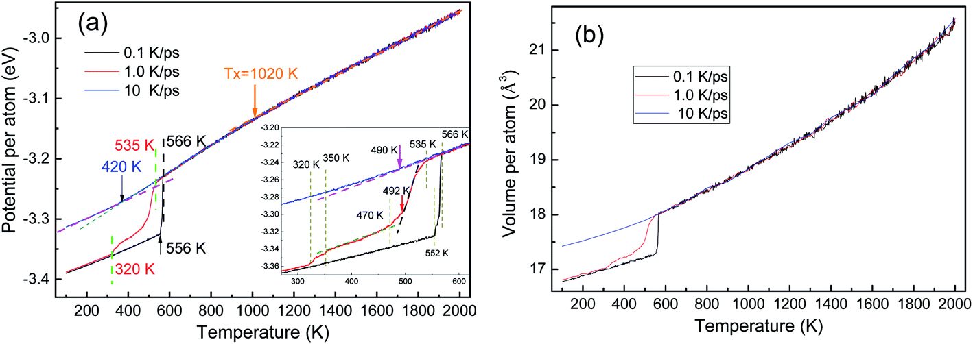 | ||
| Fig. 2 Temperature dependencies of the potential and volume of atoms during three rapid solidifications: (a) E–T curve and (b) V–T curve; the inset in (a) provides details in the vicinity of phase transitions. | ||
By linear-fitting the E–T curves at the low temperature end, the end temperature (Te) of phase transition can be obtained, and they are 420 K, 320 K, and 556 K at 10 K ps−1, 1.0 K ps−1 and 0.1 K ps−1, respectively. During the vitrification process at 10 K ps−1, the critical temperatures of Ts = 490 K and Te = 420 K are consistent with the results in ref. 4. A generally accepted definition of the glass transition temperature Tg is now not available, and several methods can be used to determine the critical temperature Tg, as proposed in ref. 30. In the present work, we simply set Tg = Te. With the same fitting technique, the onset temperatures (Ts) of phase transitions were also obtained as 490 K, 535 K, and 566 K. At a further higher temperature, there is another critical point Tx ∼ 1020 K, are there some detectable structural changes here?
The crystallization at the two lower cooling rates undergoes metastable states. At 0.1 K ps−1, the metastable state only exists in a very small temperature range from 566 K to 552 K (see the inset of Fig. 2(a)), while at 1.0 K ps−1, the metastable state is rather longtime lived. At 1.0 K ps−1, the first-order phase transition basically ends at T = 470 K, where the average potential energy (APE) begins to decrease linearly again, till 350 K; and then in [350, 320] K there seems another phase transition, because the APE drops again.
Fig. 3(a) shows the evolution of PDF curves during the crystallization at 1.0 K ps−1. As shown in the inset of Fig. 3(a) our simulation results are in good agreement with the experimental PDF data4 at T = 943 K and 1323 K, which validates the MD model. Therefore, this potential used in the present work reflects the essential physics of pure Al, and hence, the simulation results are reliable.
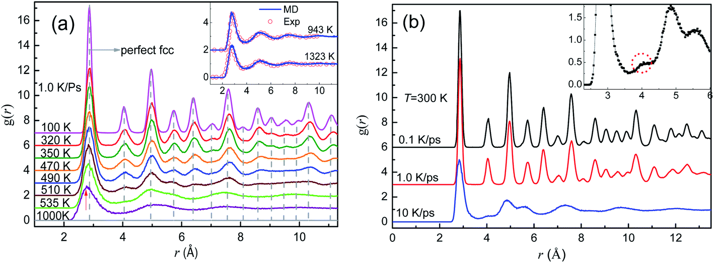 | ||
| Fig. 3 PDF curves for liquids and solids of pure Al. (a) PDF curves at eight typical temperatures during rapid cooling at 1.0 K ps−1; the dotted vertical dash lines are for the perfect FCC Al crystal and the inset compares the experimental data (hollow circles) and simulation results (lines) at 943 K and 1323 K. (b) PDF curves for the cooled system at 300 K obtained at three cooling rates; the inset provides the details of the mini-peak between the 1st and 2nd primary peaks on the PDF curve obtained at 10 K ps−1. | ||
At 1.0 K ps−1, the two PDF curves for the samples at 1000 K and Ts = 535 K are rather similar (only three distinct peaks), and for each curve, the height of the first peak is much higher than that of the others, which is typical for liquid metals. When Ts > T > 470 K, the PDF shows the essential characteristics of crystals: new peaks gradually appear between the three major peaks, and these peaks become sharper as the temperature decreases, indicating the formation of medium- and long-range orders. With the further decrease in temperature, many new peaks appear, and the relative height and position of all peaks agree well with those of the ideal FCC Al crystal.31 Therefore, liquid Al crystallizes into a fairly perfect FCC phase at a cooling rate of 1.0 K ps−1, and the solidification process is called FCC-crystallization. Almost identical are the PDF curves for the final solids obtained at the two slower cooling rates, demonstrated by the upper two PDF curves in Fig. 3(b). The amorphous characteristic of metallic glass at 300 K obtained at 10 K ps−1 is demonstrated by the typical split of the second peak, whereas the mini-peak (highlighted by the dotted circle in the inset of Fig. 3(b)) between the first and second primary peaks seems indicating some degrees of crystallization.
3.2 Evolution of the first peak and valley of g(r) curves
Usually, the volume of metals decreases as the temperature decreases. However, Fig. 3(a) shows that as the temperature decreases, the first peak of g(r) curves moves to the right (comparing the red up-arrow and the leftmost vertical dotted line), indicating that the most probable distance between the nearest neighbors increases rather than decreases, which coincides with the previously reported anomalous peak shift.32,33 In order to investigate this issue in depth, we calculated the evolution of the position (Dp), height (Hp), and width (Wp) of the first peak of g(r) curves, where Wp is defined as the distance between two points whose height is half of Hp. Similarly, the position, height and width of the first valley are denoted as Dv, Hv, and Wv respectively, where Wv is the distance between two points that are higher than the bottom of the first valley by Δ = 8%. The definition of Wv is different from Wh, because Hv is almost zero, and thus, half of the bottom cannot be identified on any g(r) curves; furthermore, the bottom of the first valley on the g(r) curve for both crystalline and amorphous solids is quite flat (see Fig. 3), so that a little Δ is enough to catch their characteristics.From Fig. 4, it can be found that before the liquid–solid phase transition occurs, all the six parameters are basically independent of the cooling rate, and at the beginning of the liquid–solid phase transition, they change dramatically. In other words, the effect of cooling rate on the structure of metal melts cannot be detected by these PDF-based parameters before the onset of phase transition.
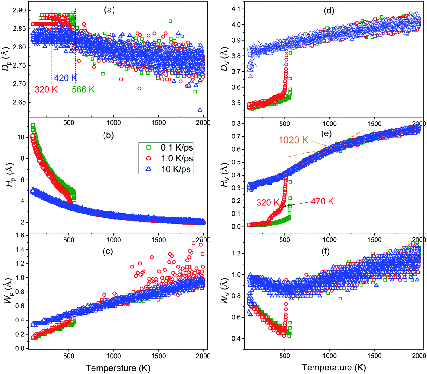 | ||
| Fig. 4 Temperature dependence of the position (a), height (b), and width (c) of the first peak; as well as the position (d), height (e) and weight (f) of the first valley on the PDF curves during the cooling process at three cooling rates of 0.1 K ps−1, 1.0 K ps−1 and 10 K ps−1. | ||
As the temperature decreases, the system volume decreases (see Fig. 2(b)), but contrary to the intuition, the most probable distance (Dp) between the nearest neighbors does not decrease but increases. Based on the concept of inherent structures (ISs) obtained by energy minimization using the conjugate gradient method, this “abnormal” trend has been examined systematically.32,33 It is argued that the apparent shift of the peak maximum can be a result of the asymmetric shape of the peak, as the asymmetry increases with the temperature-induced spreading of neighboring atoms to shorter and longer distances due to the anharmonic nature of the interatomic interaction potential. It reflects the influence of thermodynamic factors on the system structure, as discussed in ref. 34. As the temperature decreases, the kinetic energy of the atoms decreases, leading to a decrease of both chances for particles: (1) overcoming the repulsive force between them to get closer, or (2) overcoming the attraction to make them farther apart. If the interaction between atoms is symmetrical with respect to the most probable distance of IS, Dp must increase. In fact, the strength of interaction between atoms decreases rapidly with the increase in distance. Therefore, if the repulsive force increases fast enough, Dp can decrease; otherwise, Dp increases. Compared with ionic and covalent bonds, metal bonds are generally much weaker, thus Dp increases for metals when the temperature decreases.
After the onset of glass transition, atoms are frozen at their instant positions, thus Dp keeps a constant (see the blue triangles in Fig. 4(a)). However, most of atoms should be at their equilibrium positions during nucleation, thus Dp approaches to the lattice constant with a significant decrease in potential energy (see Fig. 2(a)). In brief, the intensive thermal fluctuation of atoms at high temperatures may decrease the value of Dp, while such fluctuation decreases with the decrease in temperature, which may result in a higher Dp at a lower temperature.
Usually, a higher Hp and a smaller Wp indicate that the peak is stronger and more distinct, and hence, the system is more ordered. As shown in Fig. 4(b) and (c), during the vitrification process, Hp increases exponentially and Wp decreases linearly, so the order of the system increases monotonically. Near Ts of crystallization, Hp hikes and grows exponentially, while Wp drops off and then decreases linearly, consistent with the significant improvement in the order of the system during crystallization.
Herein, Dv is the position where the probability of finding neighbors gets the minimum. For an ideal crystalline or amorphous solid, Dv is at the middle of the first and second peaks. Therefore, Dv, Hv and Wv are correlated with the specific distribution of atoms between the first and second neighbor shells. Fig. 4(d)–(f) reveal that at 10 K ps−1 Dv, Hv and Wv all change smoothly, indicating the mild structural changes during the vitrification process. On the contrary, at two lower cooling rates, the significant drop-off in the vicinity of Ts indicates the drastic structural change during nucleation. As the temperature decreases, Dv and Hv both decrease monotonically, while Wv decreases first till the end of nucleation or vitrification and then increases.
Very interestingly, only the Hv–T curve highlights the intermediate state during the rapid cooling at 1.0 K ps−1, indicating that the intermediate state is more related to the change in the medium-range structure (beyond the nearest neighbor). Furthermore, the critical temperature Tx = 1020 K (see Fig. 2(a)) can also be identified on the Hv–T curve, thus some subtle structure change beyond the nearest neighbors occurs at Tx. In addition, Wv decreases to a minimum value at the beginning of the liquid–solid phase transition, and then increases inversely; therefore, after phase transition, the primary structure change happens beyond the nearest neighbors.
3.3 Evolution of crystalline structures
The local structures in the system are quantified by LaSCA. The evolution of three typical crystalline (FCC, HCP and BCC) LaSCs is depicted in Fig. 5. During crystallization at 1.0 and 0.1 K ps−1, the number of FCC and HCP atoms increases rapidly at T < Ts, and the amount of FCC atoms is much more than that of HCP ones (see Fig. 5(a) and (c)); while that of BCC atoms is almost unchanged except a tiny intermediate increase (see Fig. 5(b) and (d)) that occurred at the early stage of crystallization, and always very small, less than 0.2% of all atoms in the system. For the glass transition process at 10 K ps−1, when T < Tg the amount of crystalline structures also increases at a lower rate and results in a small number at 300 K, including FCC-0.7% and HCP-1.32% (Fig. 5(e)). Therefore, there exists local crystallization in the amorphous solid, consistent with the mini-peak between the first and second major peaks on the bottom PDF curve shown in Fig. 3(b) and the inset of Fig. 3(b). This result is in agreement with the structure analysis based on the elasticity theory,35 where solid non-crystalline aluminum contains only about 3% of defects, and atomic configurations are similar to dumbbell interstitials in the crystalline state.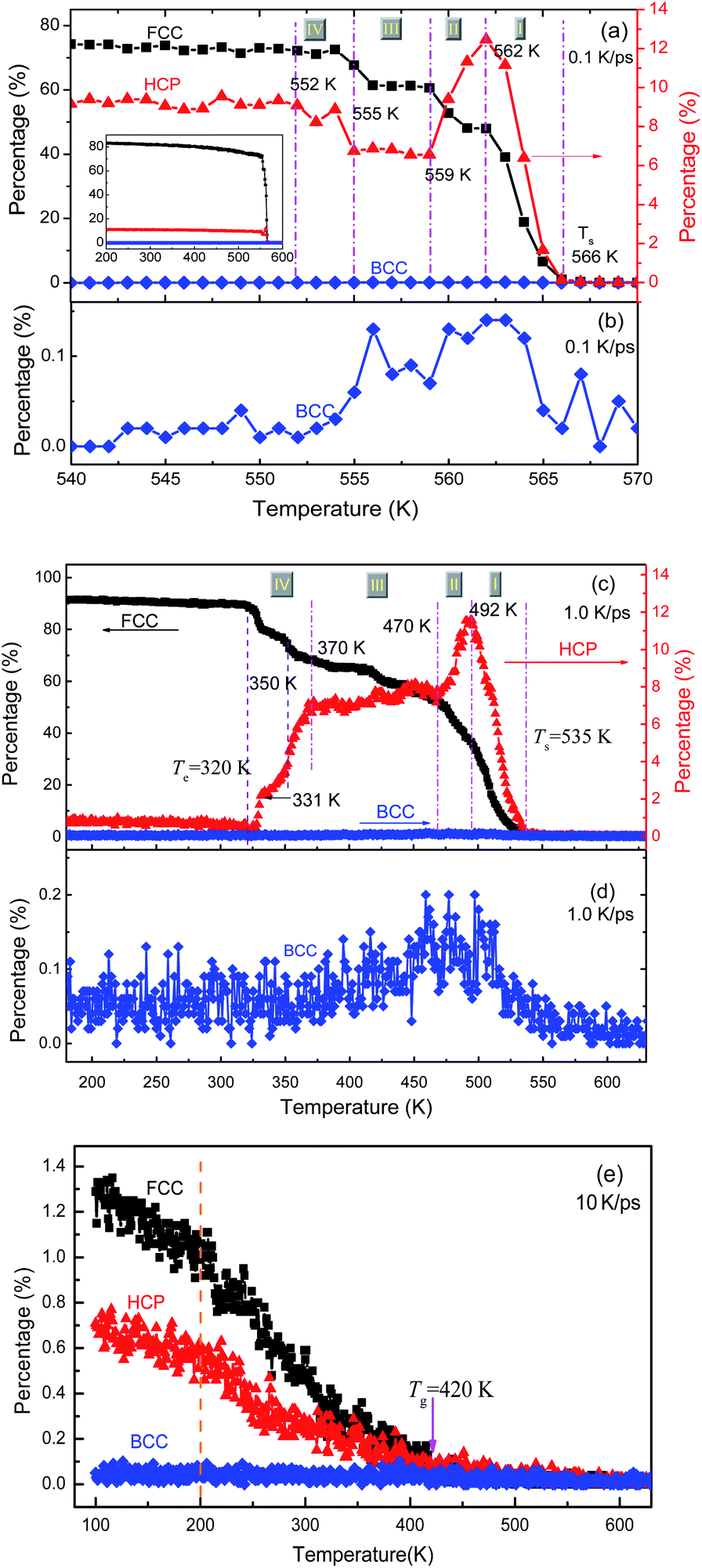 | ||
| Fig. 5 Percentage of FCC, HCP and BCC atoms as a function of temperature at three cooling rates: (a) and (b) 0.1 K ps−1; (c) and (d) 1 K ps−1; (e) 10 K ps−1. | ||
For the crystallization at 0.1 and 1.0 K ps−1, when T < Ts, the number of FCC atoms always increases monotonically with the decrease in T. However, the evolution of HCP atoms shows alternate increase and decrease in the whole solidification process. In particular, according to the evolution of HCP atoms, the FCC-crystallization can be divided into four stages by five critical temperatures (as shown in Fig. 5(a) and (c)), which are {566 K, 562 K, 559 K, 555 K, 552 K} at 0.1 K ps−1; and {535 K, 492 K, 470 K, 370 K, 320 K} at 1.0 K ps−1, respectively. At 0.1 K ps−1, the temperature ranges are {4 K, 3 K, 4 K, 3 K} for stage I to IV, which is obviously much shorter than {43 K, 22 K, 100 K, 50 K} at 1.0 K ps−1. Thus, the slower the cooling rate, the shorter the intermediate state lifetime, which may be unobservable when the cooling rate is low enough, such as 106 K ps−1 that can be implemented in experiments at present.
At stage I–III, the evolution of the number of HCP atoms during the two FCC-crystallizations is similar: in stage I, the percentage of HCP atoms increases rapidly and gets the same maximal value of about 12%; in stage II, the HCP percentage decreases rapidly to about 7% and then basically levels off at stage III. However, in stage IV, the evolution of the number of HCP atoms is opposite under the two cooling rates of 1.0 and 0.1 K ps−1. At 0.1 K ps−1, the percentage of HCP atoms increases from 7% to 9% (at 552 K), while that at 1.0 K ps−1 decreases step by step to almost zero (at 320 K). Finally, at 100 K, the amounts of FCC atoms are respectively 84% and 92% in the samples obtained at 0.1 K ps−1 and 1.0 K ps−1, and those of HCP atoms are 11% and 0.9% respectively, and the total percentages of FCC and HCP atoms are 94.4% and 92.9% respectively. Therefore, the systems resulting from the cooling rates of 0.1 K ps−1 and 1.0 K ps−1 are both perfect FCC crystals, which are consistent with the previous studies.5,36–40 At 10 K ps−1, the total number of FCC and HCP atoms is about 2% in the final amorphous solid at 100 K (see Fig. 5(e)).
As shown in Fig. 6(a) and (c), at the onset temperature of stage I, the small number of HCP and FCC atoms (almost no BCC atoms) are in order and aggregated somewhere in the system; while the ICO atoms homogeneously distribute in space. At the end of stage I, the total crystalline atoms reached over 50% (refer to Fig. 5(a) and (c)), thus the nucleation and growth of crystals were basically achieved. The spacious distribution of crystalline atoms reveals that the HCP atoms are actually the grain boundaries or defects in the FCC crystal (see Fig. 6(b) and (d)).
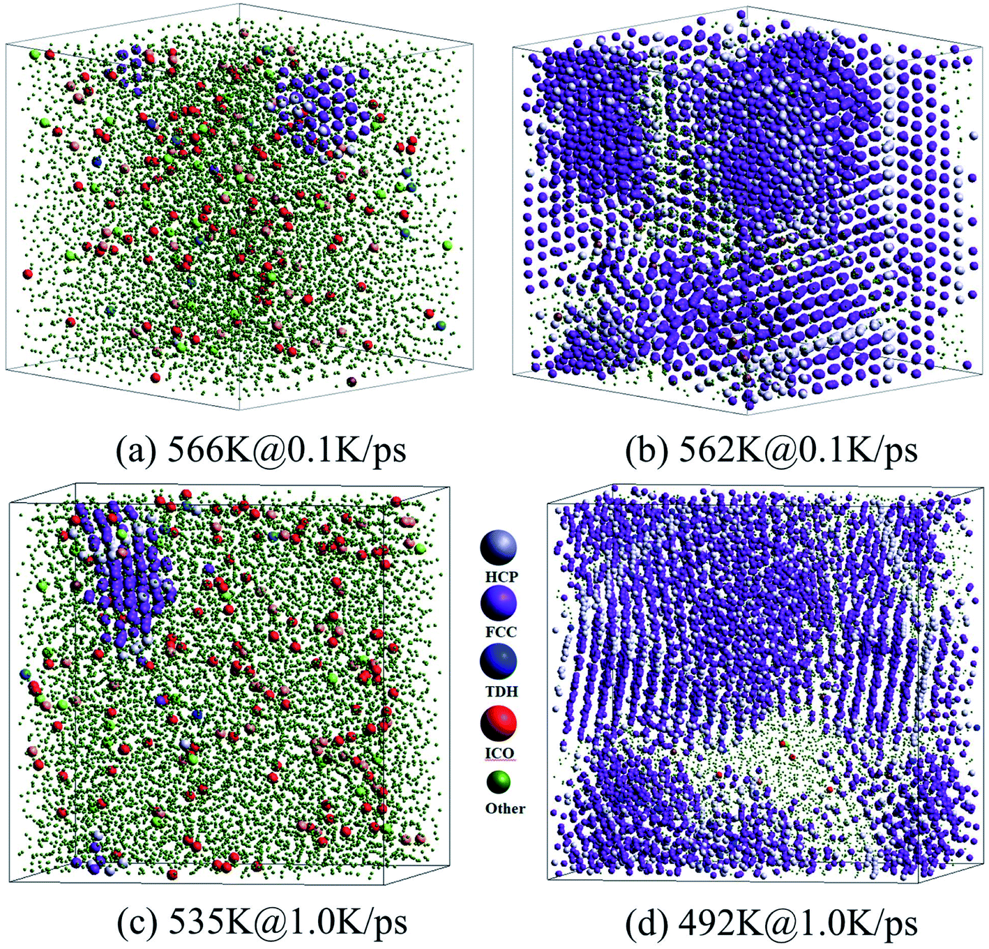 | ||
| Fig. 6 Three-dimensional views of atoms in the samples at the start and end of stage I during two FCC-crystallizations, at cooling rates of 0.1 K ps−1 (a) and (b) and 1.0 K ps−1 (c) and (d). For clarification, green atoms (represent other atoms except HCP, FCC, TDH, and ICO atoms) are indicated by smaller balls. | ||
Therefore, the structural evolution after stage I was mainly determined by the state of crystalline grains, e.g., the distribution and shape of grain boundaries (HCP atoms). With much less numbers, the grain boundary atoms (including HCP, TDH (truncated decahedron), and ICO atoms) can outline the shape and distribution of FCC regions more clearly in 3D views, thus we render them in Fig. 7 in a viewpoint that can better demonstrate the orientation and distribution of crystalline regions. Usually, HCP atoms form planes (or layers) that are shared by neighboring FCC regions. If FCC regions are in the same orientation, they form parallel twins, as shown in Fig. 7(c) and (d); otherwise, they form complex twinned structures, including five-fold twins that are characterized by lines of TDH atoms, as demonstrated in Fig. 7(f)–(h).
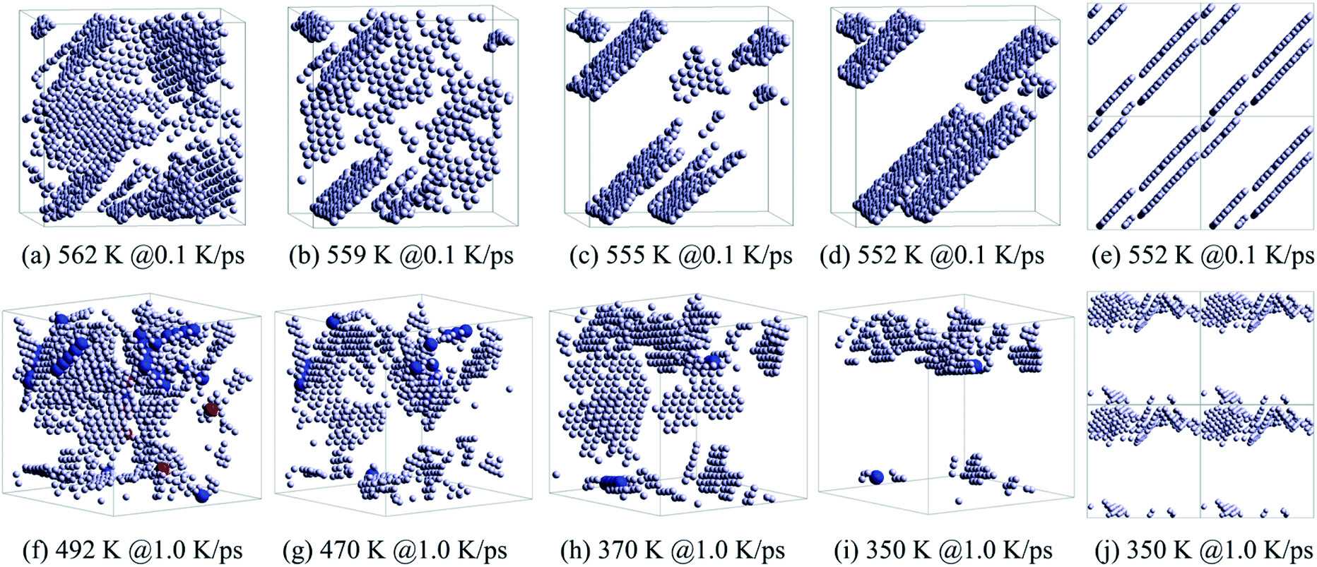 | ||
| Fig. 7 Evolution of grain boundaries, focusing on the distribution of HCP, TDH and ICO atoms in the system obtained at 0.1 K ps−1 (a)–(d) and 1.0 K ps−1 (f)–(i). The distribution of HCP atoms with PBCs in the system: (e) at 552 K obtained at 0.1 K ps−1 and (j) at 350 K obtained at 1.0 K ps−1. The legend is the same as shown in Fig. 6. | ||
Generally, small metastable HCP regions isolated by FCC regions are easy to be transformed into stable FCC structures, because only local atom rearrangement is enough. Therefore, the number of HCP atoms decreases between 562 K and 559 K at 0.1 K ps−1 (see Fig. 5(a)) with the disappearance of small orientation-disordered HCP regions (Fig. 7(a) and (b)); and the distribution of HCP atoms at 559 K is rather ordered: several parallel layers with some incomplete slices. Similarly, at 1.0 K ps−1 such HCP–FCC transformation (Fig. 7(f) and (g)) not only leads to a decrease in HCP atoms (see Fig. 5(c)), but also makes some five-fold twin structures disappear.
In stage III, there is no essential change in the distribution of HCP atoms, only the parallel layers become more regular and complete (Fig. 7(c) and (h)). Therefore, there is no distinct change in both the number of HCP atoms (see Fig. 5(a) and (c)) and the energy evolution of the system (Fig. 2(a)). For the cooling process at 1.0 K ps−1, an important change is that the five-fold structures have basically disappeared.
At the end of stage III, for cooling at 0.1 K ps−1, several parallel HCP planes have basically formed. A small displacement of crystal planes can repair such dislocation,28 resulting in a rapid decrease in the number of HCP atoms. However, if the required displacement is contradictory (refer to Fig. 7(e)), the neighboring dislocations are difficult to be eliminated (dislocation pinning), but may even grow (Fig. 5(a)). This is exactly what happens between 555 K and 552 K. After such dislocation pinning is formed (see Fig. 7(e)), the crystal structure will change no longer, so that the number of HCP and FCC atoms keep unchanged at T < 552 K.
At 1.0 K ps−1 at the end of stage III, the orientation of HCP regions are still disordered (see Fig. 7(h)) and without the hamper of five-fold twin structures, so that it is easy to transform into the stable FCC atoms. Therefore, the number of HCP atoms decreases remarkably at T < 370 K. At 350 K, there are still disordered HCP regions (see Fig. 7(i) and (j)), thus the HCP–FCC transformation is continuous, and the number of HCP atom decreases to almost zero at 320 K (see Fig. 5(c)).
In brief, in stage I (the nucleation stage), the metastable HCP atoms as the grain boundaries or defects of the FCC crystal grow rapidly. These small orientation-disordered HCP regions can easily be transformed into the stable FCC atoms till only several parallel HCP layers are left, resulting in a rapid increase in FCC atoms and the distinct decrease in HCP atoms. Such stage II can be called orientation-disordered metastable HCP-region transformation (ODMHT) stage. The next (stage III) can be called grain boundary regularization (GBR) stage, where there is no essential change in the distribution of HCP atoms, only the parallel layers become more regular and complete. At the end of GBR stage, if dislocation pinning is formed, then no more structure evolution occurs, otherwise another ODMHT happens again.
Finally, a regular five-fold twin structure is difficult to be transformed into other structures, because collective and coordinated movement of a group of atoms is necessary. It is the transformation of small orientation-disordered HCP regions in the ODMHT stage that eliminates these small five-fold twin structures and enables further structure evolution.
4 Conclusions
With the EAM potential, MD simulations for the rapid cooling of pure Al at three cooling rates have been conducted. The characteristic values of the PDF curves have been investigated systematically, including the position Dp, height Hp and width Wp of the first peak, as well as {Dv, Hv, Wv} of the first valley. Focusing on the metastable HCP regions, the structure evolution of crystalline structures has also been extensively examined with the parameter-free LaSCA. The conclusions are as follows:(1) Pure Al is easily cooled into FCC crystals, which are very difficult to vitrify. Local crystallization still occurs even if the cooling rate is high up to the critical 10 K ps−1 that results in an amorphous solid overall.
(2) The higher the cooling rate, the lower the onset temperature of crystallization; and at a subcritical cooling rate, the crystallization includes intermediate states.
(3) As the temperature decreases, Wv decreases first and then increases, but other characteristic values of PDF curves change monotonically: Dp and Hp increase, while Wp, Dv, and Hv decrease.
(4) At Ts all these characteristic values jump (up or down) for crystallization, while change continuously for vitrification. Not only the intermediate states but also Tx can be captured by Hv, so it is an important structure parameter.
(5) After nucleation, metastable HCP regions experience 3 stages: HCP–FCC transformation, region-regularization, and dislocation pinning or HCP–FCC transformation again, and dislocation pinning terminates structural evolution.
These findings are useful in understanding the phase transition under rapid cooling, while there are two issues that need to be investigated in the future: what structural changes take place near Tx and whether there is any technique that can detect the effect of different cooling rates on the system energy, PDF curve, and local structures at T > Ts.
Conflicts of interest
The authors declare that there is no conflict of interest.Acknowledgements
This work has been supported by the National Natural Science Foundation of China (Grant No. 51661005, 11764005 and 12004053). The authors are grateful to the Natural Science Foundation of Hunan Province (Grant No. 2018JJ3560), the Natural Science Foundation of Jiangxi Province (Grant No. 20181BAB216001), the Foundation of the Education Department of Jiangxi Province (Grant No. GJJ180808), and it was also supported by the GHfund B (20210702).References
- B. J. Singh and H. S. Sodhi, RSM: A Key to Optimize Machining: Multi-response Optimization of CNC Turning with Al-7020 Alloy, Anchor Academic Publishing, 2014 Search PubMed.
- S. Kumar, Graphene Engendered aluminium crystal growth and mechanical properties of its composite: an atomistic investigation, Mater. Chem. Phys., 2018, 208, 41–48 CrossRef CAS.
- Z.-y. Hou, Z.-a. Tian, Y.-f. Mo and R.-s. Liu, Local atomic structures in grain boundaries of bulk nanocrystalline aluminium: a molecular dynamics simulation study, Comput. Mater. Sci., 2014, 92, 199–205 CrossRef CAS.
- Z.-y. Hou, K.-j. Dong, Z.-a. Tian, R.-s. Liu, Z. Wang and J. G. Wang, Cooling rate dependence of solidification for liquid aluminium: a large-scale molecular dynamics simulation study, Phys. Chem. Chem. Phys., 2016, 18(26), 17461–17469 RSC.
- C. Desgranges and J. Delhommelle, Molecular simulation of the crystallization of aluminum from the supercooled liquid, J. Chem. Phys., 2007, 127(14), 144509-6 CrossRef PubMed.
- F. Li, X. J. Liu, H. Y. Hou, G. Chen and G. L. Chen, Structural origin underlying poor glass forming ability of Al metallic glass, J. Appl. Phys., 2011, 110(1), 013519 CrossRef.
- J. J. Han, C. P. Wang, X. J. Liu, Y. Wang, Z. K. Liu, T. Y. Zhang and J. Z. Jiang, Abnormal correlation between phase transformation and cooling rate for pure metals, Sci. Rep., 2016, 6, 22391 CrossRef CAS PubMed.
- J. Zhang, Y.-y. Yao, L. Sheng and J. Liu, Self-fueled biomimetic liquid metal mollusk, Adv. Mater., 2015, 27(16), 2648–2655 CrossRef CAS PubMed.
- G. X. Li, Y. F. Liang, Z. G. Zhu and C. S. Liu, et al., Microstructural analysis of the radial distribution function for liquid and amorphous Al, J. Phys.: Condens. Matter, 2003, 15(14), 2259–2267 CrossRef CAS.
- F.-x. Liu, R.-s. Liu, Z.-y. Hou, H.-r. Liu, Z.-a. Tian and L.-l. Zhou, Formation mechanism of atomic cluster structures in Al-Mg alloy during rapid solidification processes, Ann. Phys., 2009, 324(2), 332–342 CAS.
- Z.-y. Hou, L.-x. Liu, R.-s. Liu, Z.-a. Tian and J.-g. Wang, Short-range and medium-range order in rapidly quenched Al50Mg50 alloy, J. Non-Cryst. Solids, 2011, 357(5), 1430–1436 CrossRef CAS.
- R. K. Koju and Y. Mishin, Atomistic study of grain-boundary segregation and grain-boundary diffusion in Al-Mg alloys, Acta Mater., 2020, 201, 596–603 CrossRef CAS.
- H. Jones, A perspective on the development of rapid solidification and nonequilibrium processing and its future, Mater. Sci. Eng., A, 2001, 304, 11–19 CrossRef.
- J.-y. Mo, B.-l. Shen, Y.-x. Wan, Z.-d. Zhou, B. Sun and X.-b. Liang, The effect of thermal history on structure and mechanical properties of Cu64Zr36 metallic glass, J. Non-Cryst. Solids, 2020, 528, 119742–119746 CrossRef CAS.
- C. S. Liu, Z. G. Zhu, J.-c. Xia and D. Y. Sun, Cooling rate dependence of structural properties of aluminium during rapid solidification, J. Phys.: Condens. Matter, 2001, 13(9), 1873–1890 CrossRef CAS.
- K. Vollmayr, W. Kob and K. Binder, Cooling-rate effects in amorphous silica: a computer-simulation study, Phys. Rev. B: Condens. Matter Mater. Phys., 1996, 54(22), 15808–15827 CrossRef CAS PubMed.
- P. Jund, D. Caprion and R. Jullien, Is There an Ideal Quenching Rate for an Ideal Glass?, Phys. Rev. Lett., 1997, 79(1), 91–94 CrossRef CAS.
- C. S. Liu, J. Xia, Z. G. Zhu and D. Y. Sun, The cooling rate dependence of crystallization for liquid copper: a molecular dynamics study, J. Chem. Phys., 2001, 114(17), 7506–7512 CrossRef CAS.
- S. J. Plimpton, Fast parallel algorithms for short-range molecular dynamics, J. Comput. Phys., 1995, 117(1), 1–19 CrossRef CAS.
- M. I. Mendelev, M. J. Kramer, C. A. Becker and M. Asta, Analysis of semi-empirical interatomic potentials appropriate for simulation of crystalline and liquid Al and Cu, Philos. Mag., 2008, 88(12), 1723–1750 CrossRef CAS.
- J. Mei and J. W. Davenport, Free-energy calculations and the melting point of Al, Phys. Rev. B: Condens. Matter Mater. Phys., 1992, 46(1), 21–25 CrossRef CAS PubMed.
- S. Nose, A unified formulation of the constant temperature molecular dynamics methods, J. Chem. Phys., 1984, 81(1), 511 CrossRef CAS.
- H. C. Andersen, Molecular dynamics simulations at constant pressure and/or temperature, J. Chem. Phys., 1980, 72(4), 2384–2393 CrossRef CAS.
- J. Martyna Glenn, J. Tobias Douglas and L. Klein Michael, Constant pressure molecular dynamics algorithms, J. Chem. Phys., 1994, 101(5), 4177–4189 CrossRef.
- M. Kbirou, S. Trady, A. Hasnaoui and M. Mazroui, Cooling rate dependence and local structure in aluminum monatomic metallic glass, Philos. Mag., 2017, 97(30), 2753–2771 CrossRef CAS.
- Z.-a. Tian, R.-s. Liu, K.-j. Dong and A.-b. Yu, A new method for analyzing the local structures of disordered systems, Europhys. Lett., 2011, 96(3), 36001–36006 CrossRef.
- Z.-a. Tian, K.-j. Dong and A.-b. Yu, Structural evolution in the packing of uniform spheres, Phys. Rev. E: Stat., Nonlinear, Soft Matter Phys., 2014, 89(3), 032202–032209 CrossRef CAS PubMed.
- Z.-a. Tian, K.-j. Dong and A.-b. Yu, Structural evolution in the crystallization of rapid cooling silver melt, Ann. Phys., 2015, 354, 499–510 CAS.
- Z.-a. Tian, L.-l. Zhou, Y.-f. Mo, Y.-c. Liang and R.-s. Liu, Cooling rate dependence of the polymorph selection during rapid solidification of liquid metal zinc, Trans. Nonferrous Met. Soc. China, 2015, 25(12), 4072–4079 CrossRef CAS.
- L. N. Kolotova, G. E. Norman and V. V. Pisarev, Glass transition of aluminum melt. Molecular dynamics study, J. Non-Cryst. Solids, 2015, 429, 98–103 CrossRef CAS.
- Y. Waseda, The structure of non-crystalline materials, New York, McGraw-Hill, 1980 Search PubMed.
- J. Ding, M. Xu, P. F. Guan, S. W. Deng, Y. Q. Cheng and E. Ma, Temperature effects on atomic pair distribution functions of melts, J. Chem. Phys., 2014, 140, 064501–064508 CrossRef CAS PubMed.
- J. Ding and E. Ma, Computational modeling sheds light on structural evolution in metallic glasses and supercooled liquids, npj Comput. Mater., 2017, 3, 9 CrossRef.
- Y.-f. Mo, Z.-a. Tian, L. Lang, R.-s. Liu, L.-l. Zhou, Z.-y. Hou, P. Peng and T.-y. Zhang, The short-range order in liquid and A15 crystal of zirconium, J. Non-Cryst. Solids, 2019, 513, 111–119 CrossRef CAS.
- E. V. Goncharova, R. A. Konchakov, A. S. Makarov, N. P. Kobelev and V. A. Khonik, Identification of interstitial-like defects in a computer model of glassy aluminum, J. Phys.: Condens. Matter, 2017, 29, 305701 CrossRef CAS PubMed.
- H. R. Wendt and F. Abraham Farid, Empirical Criterion for the Glass Transition Region Based on Monte Carlo Simulations, Phys. Rev. Lett., 1978, 41(18), 1244–1246 CrossRef CAS.
- Y. J. Lü, M. Chen, H. Yang and D. Q. Yu, Nucleation of Ni–Fe alloy near the spinodal, Acta Mater., 2008, 56(15), 4022–4027 CrossRef.
- G. Ghosh, Observation and kinetic analysis of a metastable b.c.c. phase in rapidly solidified Ni9at.%Zr and Ni8at.%Zr1at.%X alloys, Mater. Sci. Eng., A, 1994, 189, 277–284 CrossRef.
- C. Desgranges and J. Delhommelle, Molecular Mechanism for the Cross-Nucleation between Polymorphs, J. Am. Chem. Soc., 2006, 128(32), 10368–10369 CrossRef CAS PubMed.
- P. R. ten Wolde, M. J. Ruiz-Montero and D. Frenkel, Numerical calculation of the rate of crystal nucleation in a Lennard-Jones system at moderate undercooling, J. Chem. Phys., 1996, 104(24), 9932–9947 CrossRef CAS.
Footnote |
| † Li-li Zhou and Jia-ming Pan contributed equally to this work. |
| This journal is © The Royal Society of Chemistry 2021 |