 Open Access Article
Advanced asymmetric supercapacitors with a squirrel cage structure Fe3O4@carbon nanocomposite as a negative electrode
Chengxiang Sunab,
Wenxia Pan*a,
Dianyuan Zheng *ab,
Gengtao Guoc,
Yuhang Zhengd,
Jianhong Zhua and
Cheng Liue
aCollege of Energy and Electrical Engineering, Hohai University, Nanjing 210098, China
bInstitute for Clean Energy&Advanced Materials, Lianyungang Normal College, Lianyungang 222006, China
cNARI Technology Co., Ltd., Nanjing, Jiangsu 211106, China
dState Grid Jiangsu Electric Power Engineering Consulting Co., Ltd., Nanjing, Jiangsu 210008, China
eCollege of Electrical Engineering, Zhejiang University, Hangzhou 310027, China
First published on 10th December 2021
Abstract
Carbon materials have been used as negative electrodes for supercapacitor applications; nevertheless, owing to the low capacitance, they have limited ability to enhance the supercapacitor electrochemical properties. Here, we employ a facile chemical precipitation method for preparing a squirrel cage structure Fe3O4@carbon nanocomposite. In this architecture, the carbonized crosslinked bovine serum albumin (C) will play critical roles, serving as a skeleton for the deposition of Fe3O4 and a transportation pathway like “high-speed rail” for electrons, maintaining the structural stability as well as accommodating the volume expansion of Fe3O4 and facilitating electron transportation and the electrolyte ion diffusion. The iron oxide nanoparticles (Fe3O4) exhibit superior reversible redox characteristics, hence increasing the supercapacitor performance. Benefiting from a stable structure, an aqueous asymmetric supercapacitor using a CNT@Ni(OH)2 positive electrode (cathode) and Fe3O4@C negative electrode (anode) has also been assembled, which presents a high energy density of 17.3 W h kg−1 at a power density of 700 W kg−1. The strategy for choice of Fe3O4@C composites will provide new opportunities for future supercapacitors with superior cyclability and high power density.
1. Introduction
Due to the proliferation of energy consumption and environmental deterioration, it is particularly required to investigate and develop clean, efficient and renewable sources of energy and advanced energy conversion and storage technologies.1,2 High-performance energy storage devices will play a critical role for clean energy technologies, which can find numerous applications for hybrid electric vehicles, wearable personal electronics, military devices and smart power grids.3,4 Among multifarious energy storage cells devices, the supercapacitor has emerged as an efficient power source due to its long cycling life and high power density.5 However, the current supercapacitors have unsatisfactory energy density in comparison to batteries, which severely hinders their applications as excellent power sources. The energy density of supercapacitor devices is mainly determined by cell voltage (V) and specific capacitance according to the equation E = 1/2CV2. Many organic electrolytes have been employed to achieve an extended voltage window for supercapacitors, nevertheless, most of them should be assembled in an oxygen free environment owing to their environmental concerns as well as poor electrical conductivity. Therefore, constructing aqueous asymmetric supercapacitors (ASCs) has been used as a promising way to enhance energy density of supercapacitor, which can be ascribed to the contribution of their environmental friendliness as well as wide working potential windows resulting from separate potential windows of anode and cathode, respectively.Currently, many research efforts are focused on exploring advanced capacitive and faradaic electrode materials for improving the energy density of supercapacitor. Up to now, a range of high-performance faradaic cathodes have been investigated and reported for aqueous supercapacitors.6–8 Among them, nickel-based oxide is a potential one owing to their rich redox reactions and dual energy storage mechanism.9–11 On the other hand, according to the equation 1/CASC = 1/Cc + 1/Ca, the lack of superior performance anode materials brings limitation in achieving high energy density ASCs.12 In previous reports, carbon materials are usually considered as promising anode material for supercapacitors due to its good conductivity, low cost as well as wide potential window, however, the obtained energy density and specific capacitance are relatively low.13–16 In this regard, pseudocapacitive anode materials have emerged as the potential candidates, nonetheless, there is an imperative need to further explore superior performance anode material in ASCs owing to the inferior performance and limited reports by far.17–20
Currently, iron oxide hydroxide (FeOOH) and iron oxides (Fe2O3, Fe3O4) are generally used as anode materials for battery-type or supercapacitor owing to their natural abundance, low cost, wide working voltage window and high theoretical capacitance.21–23 Among them, the Fe3O4-based nanocomposite is usually recommended as the potential alternative, which exhibits good electrical conductivity of the nanocomposites due to the fast electron transportation and the alleviation of the Fe3O4 nanomaterials agglomeration.24 In particular, by virtue of the advantages of the combination of Fe3O4 (pseudocapacitor) and carbon material (EDLCs), which has been preferred as an effective way to offer high-efficiency redox reactions and increase the conductivity, for instance, Fe3O4/graphene,25 Fe3O4/carbon nanosheets,26 Fe3O4/biocarbon,27 reduced graphene oxide/Fe3O4/polyaniline.28 Although these materials have shown significant progress in pseudocapacitive performance, some of them present poor rate capability and short cycle life, which makes them insufficient in satisfying the practical applications of supercapacitors. To our knowledge, to achieve advanced anode materials with good cycling stability, excellent rate capability and high capacitance still remains a challenging work.
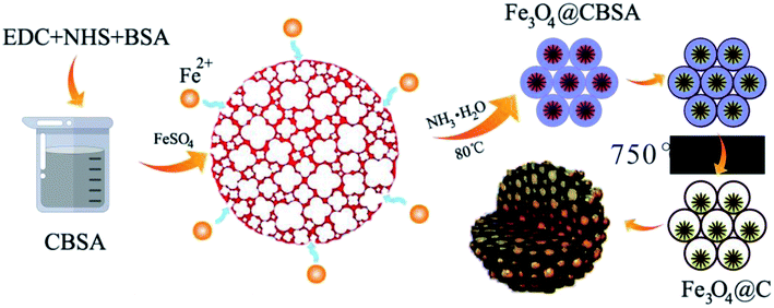
In the present work, we have developed a facile and cost effective chemical precipitation method to prepare squirrel cage structure Fe3O4@carbon (Fe3O4@C) nanocomposites, in this architecture, the carbon (C) is obtained through carbonization crosslinked bovine serum albumin at 750 °C for 2 h under nitrogen, which will play critical roles: using as a skeleton for the deposition of Fe3O4 and a transportation pathway like “high-speed rail” for electrons, maintaining the structural stability as well as accommodating the volume expansion of Fe3O4. The iron oxide nanoparticles (Fe3O4) exhibit high reversible redox characteristics, thus increasing the supercapacitor performance. By virtue of the unique structure, an ASC has also been assembled with Fe3O4@C as negative electrode (anode) and CNT@Ni(OH)2 as positive electrode (cathode), which presents good cycling stability, excellent power density and high energy density. The strategy for choice of Fe3O4@C nanocomposites offers a promising design direction for high performance supercapacitors.
2. Experimental
2.1. Materials
Bovine serum albumin (BSA), 1-ethyl-3-(3-dimethylaminopropyl) carbodiimide (EDC), N-hydroxysuccinimide (NHS), tween 80, NH3·H2O, FeSO4·7H2O, Ni(NO3)2·6H2O, ethanol and urea were obtained from Sinopharm Chemical Reagent Co., Ltd. (Ourchem Shanghai). The carbon nanotubes (CNT) were purchased from Chengdu Organic Chemicals (Chengdu, China). All chemicals and reagents employed in this study have been used as received and are of analytical grade. A Labpure water system was employed to obtain the de-ionized (DI) water.2.2. Preparation of Fe3O4@C nanomaterials
For the preparation of crosslinked BSA (CBSA) suspension, first, 50 mL BSA (2 mg mL−1) has been dissolved in de-ionized (DI) water with 0.5% tween 80 serves as the emulsifying agent, 25 mL of 75 mM EDC solution (after 15 min) 25 mM NHS and were uniformly mixed under magnetic stirring, followed by incubation for three days at room temperature, and then the CBSA nanoflower networks were achieved. Subsequently, 100 mM aqueous FeSO4 solution was added into the above CBSA suspension with continuous stirring for 3 h. Then, NH3·H2O has been added dropwise in the resulting solution, and magnetic stirred until the solution color changes from the initial dark greenish to the final black at 80 °C for 40 min to maintain pH 10. The Fe3O4@CBSA was obtained with centrifugal separation and drying the product in vacuum, and finally carbonized under nitrogen at 750 °C at a ramping rate of 1 °C for 2 h, after which a sample appeared, which was denoted as Fe3O4@C.2.3. Synthesis of CNT@Ni(OH)2 nanomaterials29,30
The CNT were treated through reflux method to make them more dispersible in DI water. In a typical process, 1 g of CNT was first refluxed in 6 M HNO3 (50 mL) for 3 h at 70 °C. Afterwards, the sample was washed with DI water several times. The pretreated CNT was collected and dried overnight at 60 °C when the neutral pH was attained.A facile chemical bath deposition procedure was employed to allow covering of CNT by Ni(OH)2 nanosheets. 0.2 g CNT was mixed with a 100 mL solution containing 0.5 M urea and 0.025 M Ni(NO3)2·6H2O through ultrasonication for 10 min. Subsequently, the mixed solution was heated for 2 h at 80 °C with constant stirring in an oil bath. Afterwards, the solution is naturally cooled to room temperature and aged for another 12 hours. This precipitate, that is CNT@Ni(OH)2 nanocomposite, was obtained through filtration and washed with DI water and ethanol several times, and dried at 60 °C for 12 h for further characterizations.
2.4. Preparation of electrode
The polyvinylidene difluoride (PTFE), electric carbon black and active material have been mixed in the ethanol (50%) with the mass ratio of 1![[thin space (1/6-em)]](https://www.rsc.org/images/entities/char_2009.gif) :
:![[thin space (1/6-em)]](https://www.rsc.org/images/entities/char_2009.gif) 1
1![[thin space (1/6-em)]](https://www.rsc.org/images/entities/char_2009.gif) :
:![[thin space (1/6-em)]](https://www.rsc.org/images/entities/char_2009.gif) 8 through ultrasonic dispersion for 0.5 h. The mixture was spread on the prepared carbon paper and further dried for 2 h at 80 °C in vacuum. Then, the carbon paper coated with active material using as the working electrode.
8 through ultrasonic dispersion for 0.5 h. The mixture was spread on the prepared carbon paper and further dried for 2 h at 80 °C in vacuum. Then, the carbon paper coated with active material using as the working electrode.
2.5. Characterization
TEM images were obtained with a FEI Tecnai G2 F20 microscope (USA). Field-emission SEM images were collected with a HITACHI S-4800 microscope (Japan). The phase purity and crystal structure of the as-synthesized samples have been achieved using an X-ray diffraction (Bruker D8 Advance) with Cu Kα X-ray source. The Fourier transform infrared instrument (FTIR) spectrum has been collected by a BRUKER TENSOR 27 (Germany) in wavenumber range 400–4000 cm−1. XPS spectra have been obtained with an Escalab 250Xi photoelectron spectrometer (USA). The pore volume, pore diameters and Brunauer–Emmett–Teller (BET) surface area were achieved at 77 K using a Autosorb iQ Station 2 instrument.2.6. Electrochemical measurement
Electrochemical measurement of the individual electrodes were carried out in a traditional three-electrode electrochemical device with Hg/HgO as a reference electrode and a platinum foil as the counter electrode with an electrochemical workstation (CHI 660E) in a 3 M KOH electrolyte. The as-prepared electrodes were used as the working electrode. Cyclic voltammetries (CV) have been performed with various scan rates (5–100 mV s−1). Cycling stability of Fe3O4@C electrode was further investigated with CVs at 50 mV s−1 for 5000 cycles. Galvanostatic charge–discharge (GCD) profiles were obtained at different current densities (1–20 A g−1). The electrochemical impedance spectroscopy (EIS) has also been performed to investigate the conductivity of Fe3O4@C electrode in a frequency range (0.01 to 105 Hz). Electrochemical properties of the assembled asymmetric cell Ni(OH)2@CNT//Fe3O4@C were assessed by GCD and CV measurements with a two-electrode asymmetric cell.The specific capacitance value of the samples was achieved from GCD profiles at various current densities by using the formulae below:
 | (1) |
The specific capacitance value of individual electrode samples can also be obtained with from the CV curves.
The energy density and power density of the fabricated supercapacitor can be obtained by using the equations below:
 | (2) |
 | (3) |
Furthermore, it is important to keep the charging balance for the two electrodes of the device to obtain high performances, the mass ratio of the positive electrode to negative electrode is adjusted based on the following equation:
 | (4) |
3. Results and discussion
A facile schematic illustration of the formation of squirrel cage structure Fe3O4 nanoparticles from FeSO4·7H2O is shown in Scheme 1, which involves several reaction processes. In the first step, FeSO4·7H2O was dissolved in DI water, resulting in Fe2+ ions. Subsequently, O2 oxidizes Fe2+ into Fe3+. With the addition of an aqueous solution of NH3·H2O, iron oxyhydroxide and ironhydroxide are acquired. Finally, Fe3O4 nanoparticles were attained through hydrothermal treatment. The Fe3O4@C was obtained by annealing with Fe3O4@CBSA at 750 °C for 2 h. The probable transformation reaction processes involved the formation of Fe3O4 and Fe3O4@C nanocomposites are displayed in eqn (5)–(9):| Fe2+ + NH4OH → Fe(OH)2 | (5) |
| Fe(OH)2 + O2 → Fe(OH)3 | (6) |
| 2Fe(OH)3 → 2FeOOH + 2H2O | (7) |
| Fe(OH)2 + 2FeOOH → Fe3O4 + 2H2O | (8) |
| C–(Fe(OH)2 + 2FeOOH) → C–Fe3O4 | (9) |
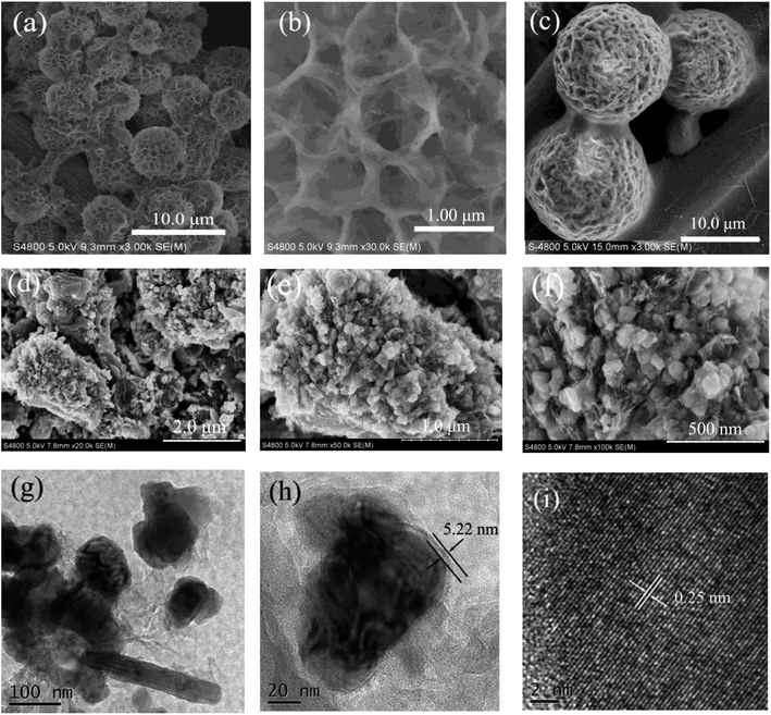
The internal microstructure and surface morphologies of the as-synthesized samples were explored with SEM and TEM. From Fig. 1a, a hierarchical CBSA nanoflower networks can be observed, which have porous microstructures with high surface-to-volume ratios. It is notable that the average size of the CBSA nanoflowers is determined to be about 3 μm. Fig. 1b shows the SEM image at higher magnification, revealing that all the petals grow from the center. The uniformly distributed Fe3O4 nanoparticle morphology in CBSA can be seen in Fig. 1c. From Fig. 1d–f, it may be seen that uniformly distributed nanoparticle morphology after Fe3O4@CBSA carbonization. The SEM images at high magnifications (Fig. 1d and e) exhibits that each Fe3O4 nanoparticle is surrounded by carbon microparticle without the observation of nanoclusters of aggregated Fe3O4 nanoparticles, which suggests formation of an interconnected morphology with squirrel cage structure.
In addition, to further study internal morphology of the as-synthesized Fe3O4@C nanoparticles, TEM images were obtained and displayed in Fig. 1g–i. From Fig. 1g and h, it can be found that numerous Fe3O4 nanoparticles exhibit the cube shape with uniform nanoparticles embedded in carbon homogeneously. The lattice fringes of Fe3O4 nanoparticles anchored on the carbon with an interplanar spacing of 0.25 nm (Fig. 1f), which is consistent with plane (311) of the cubic spinel phase.31 This analysis is in line the XRD result, which further confirms the formation of Fe3O4 nanoparticles.
The chemical composition and elemental distribution in the Fe3O4@C nanocomposite were characterized by elemental mapping. As displayed in Fig. 2c–f, elemental mappings (from TEM imaging; see Fig. 2a) demonstrate that O, N and C elements are all distributed homogeneously on the Fe matrix in the Fe3O4@C electrode material.32 Revealing the carbon particles and Fe3O4 nanoparticles are homogeneously distributed inside the nanocomposites. Interestingly, the C element mapping becomes clearer (Fig. 2f), indicating the raise of C content, which will facilitate the improvement of the conductivity properties and electron transfer for the samples. The element of N may be from the BSA.
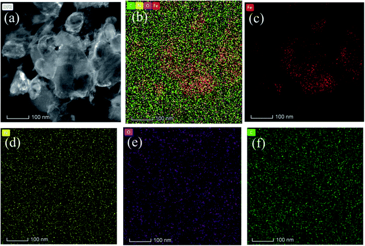 | ||
| Fig. 2 (a) TEM image of Fe3O4@C nanocomposites. (b) Overall mappings and corresponding mappings of Fe (c), N (d), O (e) as well as C (f) elements. | ||
XRD test was performed to further confirm the phase compositions of Fe3O4@C electrode. Fig. 3a depicts the XRD patterns of Fe3O4@C nanocomposite and Fe3O4 nanoparticles. Obviously, for the Fe3O4 and Fe3O4@C nanocomposite, the peaks can be indexed to the diffraction of magnetite cubic Fe3O4 (JCPDS no. 79-0417), revealing that Fe3O4 nanoparticles have high crystallinity in the nanocomposite.33
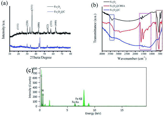 | ||
| Fig. 3 (a) XRD patterns of Fe3O4@C and Fe3O4. (b) FTIR spectra of Fe3O4, Fe3O4@CBSA, and Fe3O4@C. (c) EDS pattern of the Fe3O4@C electrode. | ||
Fourier transform infrared (FTIR) spectroscopy was carried out to assess the formation of Fe3O4 and the incorporation of Fe3O4 in the carbon. Fig. 3b shows the FTIR spectra of Fe3O4, Fe3O4@CBSA, and Fe3O4@C. As shown in Fig. 3b, the characteristic peaks at 623, 1629 and 3475 cm−1 of Fe3O4@C have been ascribed to the stretching vibration mode of (Fe–O) bonds in the lattice structure of magnetite, O–H bending, and O–H stretching, respectively.34 The characteristic bands at 1133 cm−1 corresponds to (C–N) at 1546 cm−1 peak belong to C![[double bond, length as m-dash]](https://www.rsc.org/images/entities/char_e001.gif) C, respectively.35 Finally, the FTIR spectra of bare Fe3O4@CBSA and Fe3O4@C show overall small shifts correspond to their carbonization characteristic peaks which probably results owing to the strong interaction of Fe3O4 and C, which also reflects the successful combination of Fe3O4 and carbon. The resulting Fe3O4@C nanoparticles was further studied with EDS (Fig. 3c), from where O, N and C elements are further confirmed in the Fe3O4@C electrode. Signal of Cu may be from the TEM copper grid.
C, respectively.35 Finally, the FTIR spectra of bare Fe3O4@CBSA and Fe3O4@C show overall small shifts correspond to their carbonization characteristic peaks which probably results owing to the strong interaction of Fe3O4 and C, which also reflects the successful combination of Fe3O4 and carbon. The resulting Fe3O4@C nanoparticles was further studied with EDS (Fig. 3c), from where O, N and C elements are further confirmed in the Fe3O4@C electrode. Signal of Cu may be from the TEM copper grid.
The valence states of different elements in as-synthesized Fe3O4@C nanoparticles were further investigated with XPS test. The survey XPS spectra displayed in Fig. 4a reveals the existence of Fe 2p, O 1s, N 1s and C 1s in Fe3O4@C nanoparticles. The Fe 2p core-level spectrum (Fig. 4b) presents two characteristic peaks at 711.8 and 725.3 eV corresponding to Fe 2p3/2 and Fe 2p1/2 spin orbitals of Fe3O4, together with two shake-up satellite peaks at approximately 719.6 and 730.1 eV. The Fe 2p spectrum was in line with the standard XP spectrum of Fe3O4,36 further proving the formation of magnetite Fe3O4. As depicted in Fig. 5c, the O 1s core level spectrum can be deconvoluted into three peaks at 533.3 (C–O–C), 531.3 eV (Fe–O) and 529.9 (Fe–O–C).37 It can be confirmed the formation of Fe–O–C between carbon and Fe3O4 nanoparticles. From Fig. 4d, the core level spectrum of N 1s presents characteristic nitrogen–carbon bond-related peaks which locates at 402.2 eV (oxidized N), 401.0 eV (graphitic N), 400.4 eV (pyrrolic N) and 398.5 eV (pyridinic N).
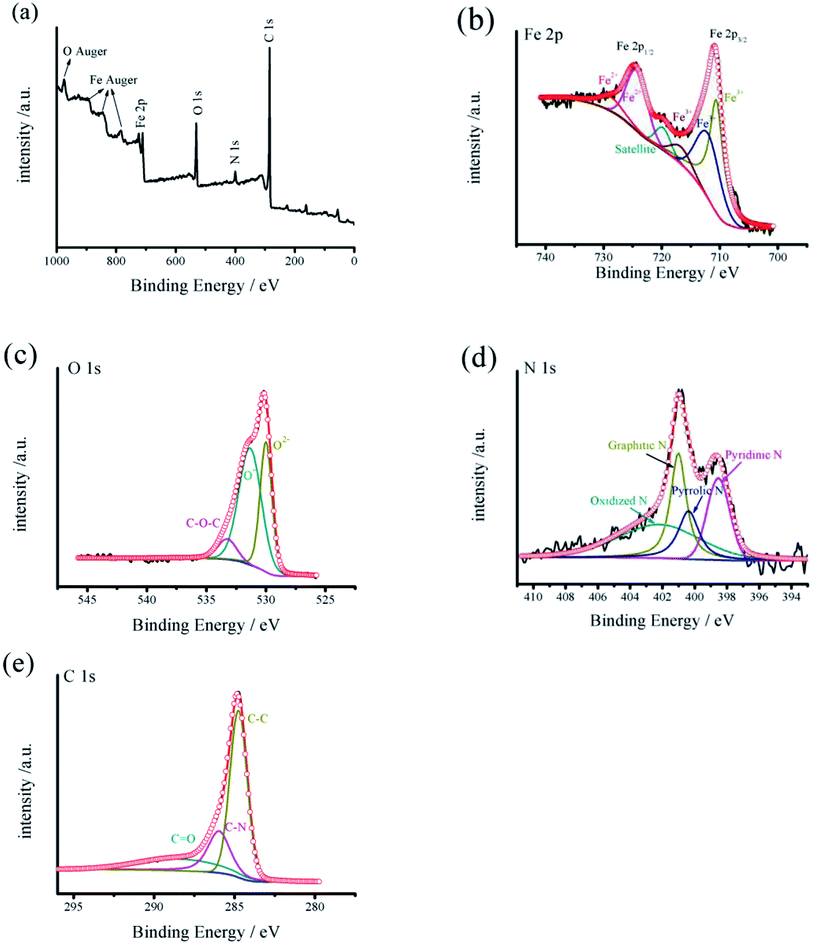 | ||
| Fig. 4 (a) XPS survey spectra of Fe3O4@C. (b–e) Deconvoluted XPS core-level spectra of Fe 2p, O 1s, N 1s and C 1s in the as-prepared Fe3O4@C nanoparticles, respectively. | ||
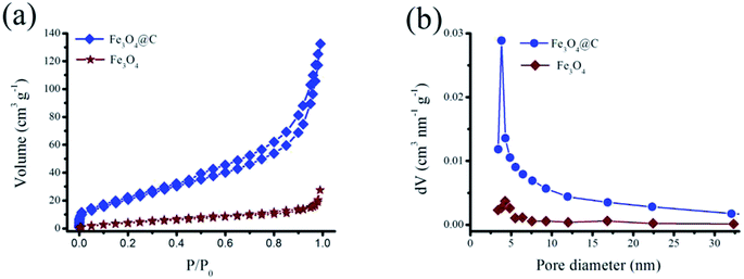 | ||
| Fig. 5 (a) Nitrogen adsorption and desorption isotherms of Fe3O4 and Fe3O4@C. (b) Pore size distribution curve of the sample. | ||
Fig. 4e exhibits C 1s core level spectrum of the nanocomposite, which can be deconvoluted into three peaks at 286.0 (C–N), 288.4 eV (C![[double bond, length as m-dash]](https://www.rsc.org/images/entities/char_e001.gif) O) and 284.8 (C–C), respectively.38 The XPS characterization confirm the successful transformation of FeSO4·7H2O to the Fe3O4 nanoparticles, which is consistent with the results of EDS, XRD, TEM, SEM and FTIR. Moreover, the unique structure characteristics of Fe3O4@C nanocomposite confirm the interconnecting morphology between the Fe3O4 nanoparticles and carbon, which will play a key role in improving electrical conductivity of Fe3O4.
O) and 284.8 (C–C), respectively.38 The XPS characterization confirm the successful transformation of FeSO4·7H2O to the Fe3O4 nanoparticles, which is consistent with the results of EDS, XRD, TEM, SEM and FTIR. Moreover, the unique structure characteristics of Fe3O4@C nanocomposite confirm the interconnecting morphology between the Fe3O4 nanoparticles and carbon, which will play a key role in improving electrical conductivity of Fe3O4.
The porous structure information of the sample was measured with nitrogen adsorption/desorption isotherms. As seen from Fig. 5a, the adsorption/desorption isotherms of Fe3O4 and Fe3O4@C exhibit type IV isotherm characteristics. Due to the open microstructure, the BET specific surface area of Fe3O4@C is measured to be 82.20 m2 g−1, which is more over 4 times value of Fe3O4 (17.92 m2 g−1). Thus, a high surface area of Fe3O4@C facilitates fast ion access and efficient penetration of electrolyte,37 and also takes a task to cushion volume expansion of Fe3O4 upon during cycling test. The corresponding pore size distribution profiles of Fe3O4@C and Fe3O4 were determined according to the adsorption particulars with the Barrett–Joyner–Halenda method (BJH), as displayed in Fig. 5b, thus confirming the mesoporous structure of the sample. It is observed that the Fe3O4@C exhibits a normal pore size of 3.82 nm, which can fit comfortably for the diffusion of ions and transition of electron within the active medium. The combination of high conductivity and surface area makes Fe3O4@C attractive as a potential electrode for supercapacitors.
3.1. Electrochemical performance of the Fe3O4@C nanocomposites anode
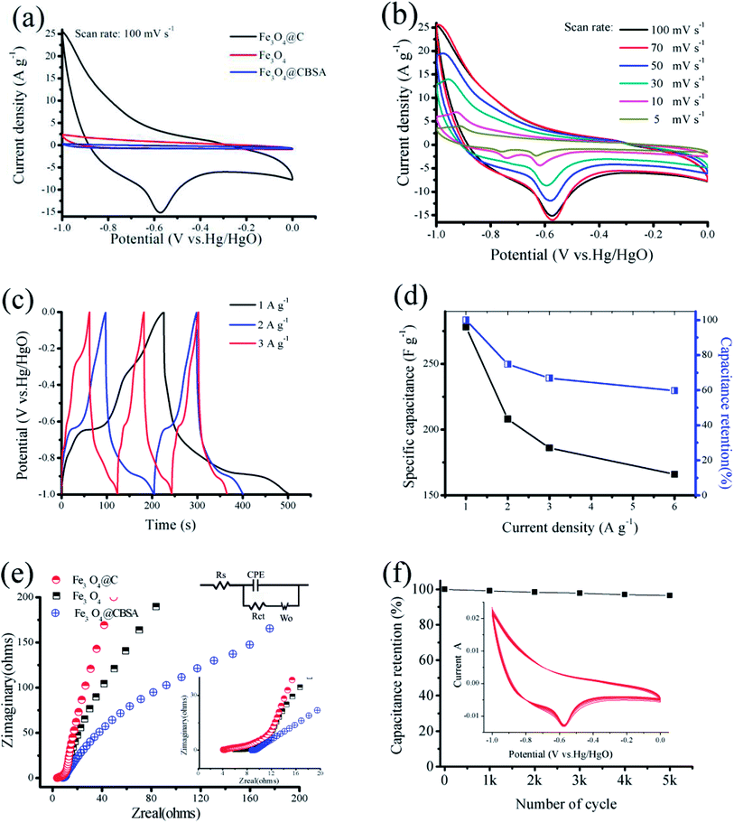
To investigate the electrochemical performance of squirrel cage structure Fe3O4@C nanoparticles, GCD and CV tests have been performed in a three-electrode cell. The CV profiles of Fe3O4, Fe3O4@CBSA and Fe3O4@C composites are shown in Fig. 6a. Clearly, the current density of the Fe3O4@C electrode is much higher than those of Fe3O4 and Fe3O4@CBSA, which exhibits a much larger charge storage capability than pure Fe3O4 or Fe3O4@CBSA. The outstanding property of Fe3O4@C composites is ascribed to its porous squirrel cage structure, in which (i) Fe3O4@C with increased electrical conductivity offers fast pathways for a high harvest of Fe3O4 pseudocapacitance and (ii) the synergistic effect of carbon and Fe3O4 nanoparticle which decreases solid-state lengths for electronic transport and ionic diffusion.Fig. 6b exhibits the CV profiles of Fe3O4@C electrode at different scan rates ranging from 5 to 100 mV s−1 versus Hg/HgO in a −1.0 to 0 V voltage windows. CV curves of the Fe3O4@C nanoparticles anode exhibit the quasirectangular shape denoting an electrochemical performance of a typical pseudocapacitive electrode.39 In this work, the CV curve exhibits the pseducapacitance behaviour due to the contribution from Fe3O4, which plays the main role. The shape of the CV curves of C electrodes is different from that of Fe3O4@C nanocomposite electrode reported here since the former revealed electrical double layer capacitive behavior and their CV curves exhibited rectangular shapes. When the scan rate increases, the current response enhances accordingly, and the shape of the CV curves is well-retained, confirming superior rate capability of the Fe3O4@C electrode. A pair of redox peaks also indicate that the reversible redox reactions of Fe(III) ↔ Fe(II).
Fig. 6c displays the GCD profiles of Fe3O4@C nanocomposites at various current densities. Fig. 6d shows the obtained specific capacitances of Fe3O4@C at different densities. The Fe3O4@C nanocomposites presents a high specific capacitance of 278 F g−1 at 1 A g−1, and even retains 60% at a high current density of 6 A g−1. The improved rate capability and increased capacitance of the Fe3O4@C nanoparticles can be ascribed to the novel designed squirrel cage structure.
EIS data have been obtained to evaluate the property of ion diffusion and conductivity of the samples (Fig. 6e). The Fe3O4@C composites exhibit Rct and Rs values of 0.35 and 2.88 Ω, respectively. There are two sections in each plot: the slope line at low-frequency region and the semicircle at high-frequency region. The slope corresponds to Warburg resistance, revealing the diffusive resistance of the electrolyte into the interior part of the electrode, whereas the semicircle represents the charge transfer resistance and controls the electron-transfer kinetics of redox reactions at the electrode surface.40,41 The equivalent series resistance (ESR) was indicated by the value of the first insertion point in high-frequency region, which corresponds to the sum of the electrode internal resistance, the ionic resistance of the electrolyte as well as the contact resistance between the current collector/substrate and active materials. The conductivity improvement of the Fe3O4@C composites was indicated by a lower ESR value of 3.886 Ω compared to Fe3O4 (5.998 Ω) and Fe3O4@CBSA (8.661 Ω), which demonstrated more accessible electrolyte diffusion to the electrode surface. Long-term cycling stability plays a key role for application of supercapacitors. CV cycling tests were performed over 5000 cycles at 50 mV s−1 to access the cycling performance. From Fig. 6f, the Fe3O4@C composites still remains 96.5% of its initial capacitance over 5000 cycles.
3.2. Electrochemical evaluation of the fabricated aqueous ASC
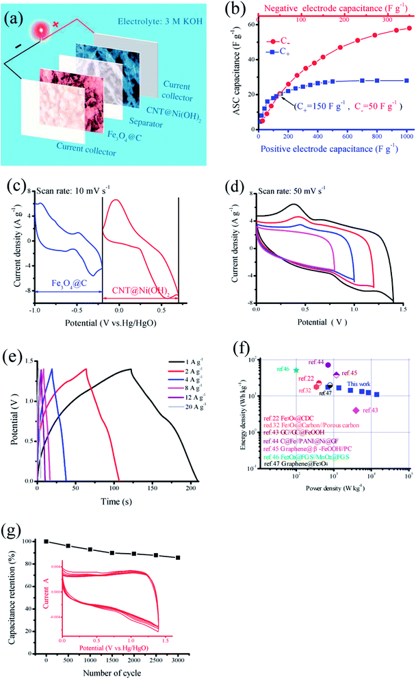
To further evaluate the real applications of this novel design, the ASC was fabricated with CNT@Ni(OH)2 (as the cathode) and Fe3O4@C nanocomposite (as the anode) in a 3.0 M KOH aqueous electrolyte, as shown in Fig. 7a. To assemble a high-performance supercapacitor, balancing the charges stored at the positive electrode (Q+) and negative electrode (Q−) is essential.42 The mass of the electrode (m), the specific capacitance (C) and the potential range for charge–discharge process (ΔV) are key parameters that determine the electrode stored charge (Q = m × C × ΔV). Given that Q+ = Q−, the mass ratio of cathode and anode can be obtained according to the eqn (4). Here, an optimized mass ratio of CNT@Ni(OH)2 and Fe3O4@C nanocomposite is 1.42.Fig. 7b shows performance of the as-prepared ASC, which reveals the relationship between the capacitance of each working electrode and total capacitance of the supercapacitor. It can be seen that if the specific capacitance of negative electrode materials (C−) was maintained at 50 F g−1, even if specific capacitance of positive electrode materials (C+) is significantly enhanced, the CNT@Ni(OH)2-based materials with a constant specific capacitance of 150 F g−1, the capacitance of the ASC reach to 21 F g−1. However, if the C− is only increased to 100 F g−1, the capacitance of the ASC can reach 35 F g−1. This indicates that C− will play a crucial role in improving the specific capacitance of the asymmetrical capacitor. Fig. 7c shows the CV profiles of both electrodes, presenting the working potential windows of −1.0 to −0.15 V for Fe3O4@C anode and −0.15–0.7 V for CNT@Ni(OH)2 cathode. These CV studies revealed that the ASC fabricated with the two as-prepared working electrodes together can possess a 1.7 V voltage window.
Furthermore, to determine the optimal working voltage window of the as-assembled CNT@Ni(OH)2//Fe3O4@C ASC, a series of CV measurements are performed in various voltage windows, as displayed in Fig. 7d. Over a 1.0 V voltage window, only one anodic peak can be seen, indicating that there is little contribution from the cathode and the reactions are irreversible. Under an extended voltage window of 1.7 V, the aqueous electrolyte will decompose. Therefore, an optimized voltage window of the fabricated ASC is determined to be 1.4 V, which is in accordance with the operating voltage windows of the individual electrode concerning the water oxidation and reduction voltages in 3 M KOH electrolyte. When enhancing voltage from 0.8 to 1.4 V at 50 mV s−1, the capacitance increases from 41.69 to 68.43 F g−1 accordingly, which can be contributed to the enhanced electrode redox reactions and it can also be demonstrated from integral area of CV curves.
A galvanostatic charging/discharging measurement was also carried out with various current densities over the potential window of 0–1.4 V, as depicted in Fig. 7e. The discharge profiles are linear but also exhibit pseudocapacitive behavior at low current densities. However, at high current densities, all GCD profiles exhibit the clear potential plateaus in the cycle process of charge–discharge, which mainly correspond to oxidation/reduction of Fe3O4 and Ni(OH)2 in the CV profiles, demonstrating the pseudocapacitive behavior of the materials, and a quick I–V response indicate good capacitive characteristics for the prepared device. The specific capacitance of the sample are determined to be 63.57, 61.29, 52.29, 48.57, 45.43 and 40.00 F g−1, respectively, at current densities of 1, 2, 4, 8, 12 and 20 A g−1 (Fig. 7e). The capacitance decrease with current density increase may be ascribed to the essential barrier to diffusion and penetration of electrolyte. In some of previous reports, such loss is distinct (up to 60–70%). However, here, the capacitance retention is 62.92% even at 20 A g−1, which indicate the as-fabricated ASC device will offer more credible capacitive performance for high power supercapacitor applications.
The energy storage property of the assembled ASC device was further investigated, Fig. 7f shows the Ragone plot, where the specific power is plotted versus specific energy. For comparison, many previously reported ASCs22,32,43–47 are also displayed in Fig. 7f. Encouragingly, the power density and energy density can reach 700 W kg−1 and 17.3 W h kg−1 at 1 A g−1, respectively. These values are comparable to other iron-based ASCs (Table 1) in aqueous electrolyte. Although, some reports have achieved high energy densities than the present work,43,44,46 our electrodes possess more stable and higher power density than them. With the current density increasing, the power density is enhanced but the energy density present slightly decreased. The energy density of our device still remains 10.89 W h kg−1 with a power density of 14![[thin space (1/6-em)]](https://www.rsc.org/images/entities/char_2009.gif) 000 W kg−1 at 20 A g−1. Thus, it clearly indicates that the assembled ASC exhibits high energy density without much decrease in power density.
000 W kg−1 at 20 A g−1. Thus, it clearly indicates that the assembled ASC exhibits high energy density without much decrease in power density.
| Electrode design | Electrolyte | Voltage range | Energy density (W h kg−1) | Power density (W kg−1) | Ref. |
|---|---|---|---|---|---|
| Fe3O4@CDC//Fe3O4@CDC | 1 M KOH | 1.6 V | 22.3 | 406 | 22 |
| Fe3O4@carbon//porous carbon | KOH/PVA | 1.4 V | 18.3 | 351 | 32 |
| GC//GC@FeOOH | 1 M Na2SO4 | 1.2 V | 36.6 | 1200 | 43 |
| CeFe/PANI/Ni-GF | 1 M NaNO3 | 1.7 V | 68.0 | 718 | 44 |
| Graphene@β-FeOOH//porous carbon | 6 M KOH | 1.6 V | 4.0 | 4000 | 45 |
| Fe2O3@FGS//MnO2@FGS | 1 M Na2SO4 | 2.0 V | 50.7 | 100 | 46 |
| Graphene/Fe3O4 | KOH/PVA | 1.6 V | 19.2 | 800.2 | 47 |
| Fe3O4@C//CNT@Ni(OH)2 | 3 M KOH | 1.4 V | 17.3 | 700 | This work |
Moreover, we further investigate the cycling stabilities of the fabricated ASC. The 3000-cycle performance of CNT@Ni(OH)2//Fe3O4@C ASC at 50 mV s−1 have been investigated (Fig. 7g). The device exhibits 93% capacitance retention over 1000 cycles. The capacitance retained ∼86% over 3000 cycles, indicating the acceptable cycling performance. The capacitance decrease may come from the loss of electroactive sites during the CV cycles.
4. Conclusions
In this work, we have investigated and assembled an advanced asymmetric supercapacitor using CNT@Ni(OH)2 nanocomposites and Fe3O4@C nanoparticles as anode and cathode, respectively. By virtue of the excellent individual capacitive performance of Fe3O4@C and CNT@Ni(OH)2 and synergistic effects between two electrodes, the fabricated device presents superior energy storage capability, namely, the device presents high energy and power densities and acceptable cycling performance in aqueous electrolyte. The enhanced performance arises from the following effects: (i) the excellent conductivity and squirrel cage structure of the Fe3O4@C nanocomposites porous networks serve as a “high-speed rail” for electrons transport and easy access for electrolyte ions to electrode surfaces; (ii) the good contact between the Fe3O4 and carbon materials produced by the carbonized process allows tight adhesion and low contact resistance between them. These results indicate that our work overcome some present challenges to achieve high energy density for supercapacitors. The work also has important implications for optimizing the supercapacitor electrochemical performance using various metallic oxide electrode materials with appropriate work potentials.Conflicts of interest
There are no conflicts to declare.Acknowledgements
The authors gratefully acknowledge the support of the National Natural Science Foundation of China (Grant No. 51377047), Qing Lan Project of Jiangsu Higher Education of China, Six Talent Peaks Project in Jiangsu Province (JNHB-220) and the 521 Engineering Program of Lianyungang.References
- K. A. Owusu, L. B. Qu, J. T. Li, Z. Y. Wang, K. N. Zhao and C. Yang, et al., Low-crystalline iron oxide hydroxide nanoparticle anode for high-performance supercapacitors, Nat. Commun., 2017, 8, 14264–14274, DOI:10.1038/ncomms14264.
- C. Hu, L. Song, Z. Zhang, N. Chen, Z. Feng and L. Qu, Tailored graphene systems for unconventional applications in energy conversion and storage devices, Energy Environ. Sci., 2015, 8, 31–54, 10.1039/c4ee02594f.
- D. Larcher and J. M. Tarascon, Towards greener and more sustainable batteries for electrical energy storage, Nat. Chem., 2014, 7, 19–29, DOI:10.1038/nchem.2085.
- S. S. Zheng, Q. Li, H. G. Xue, H. Pang and Q. Xu, A highly alkaline-stable metal oxide@metal-organic framework composite for high-Performance electrochemical energy storage, Natl. Sci. Rev., 2020, 7, 305–314, DOI:10.1093/nsr/nwz137.
- Q. Wang, Y. Ma, X. Liang, D. Zhang and M. Miao, Flexible supercapacitors based on carbon nanotube-MnO2 nanocomposite film electrode, Chem. Eng. J., 2019, 371, 145–153, DOI:10.1016/j.cej.2019.04.021.
- L. Qu, Y. L. Zhao, A. M. Khan, C. H. Han, K. M. Hercule and M. Y. Yan, et al., Interwoven three -dimensional architecture of cobalt oxide nanobrush-graphene@NixCo2x(OH)6x for high- performance supercapacitors, Nano Lett., 2015, 15, 2037–2044, DOI:10.1021/nl504901p.
- W. C. Jiang, D. S. Yu, Q. Zhang, K. Goh and L. Wei, Ternary hybrids of amorphous nickel hydroxide-carbon nanotube-conducting polymer for supercapacitors with high energy density, excellent rate capability, and long cycle life, Adv. Funct. Mater., 2015, 25, 1063–1073, DOI:10.1002/adfm.201403354.
- X. Xia, D. Chao, Z. Fan, C. Guan, X. Cao and H. Zhang, et al., A new type of porous graphite foams and their integrated composites with oxide/polymer core/shell nanowires for supercapacitors: structural design, fabrication, and full supercapacitor demonstrations, Nano Lett., 2014, 14, 1651–1658, DOI:10.1021/nl5001778.
- Z. Tang, C. H. Tang and H. Gong, A high energy density asymmetric supercapacitor from nano-architectured Ni(OH)2/carbon nanotube electrodes, Adv. Funct. Mater., 2012, 22, 1272–1278, DOI:10.1021/nl5001778 DOI:10.1002/adfm.201102796.
- D. Guo, Y. Luo, X. Yu, Q. Li and T. Wang, High performance NiMoO4 nanowires supported on carbon cloth as advanced electrodes for symmetric supercapacitors, Nano Energy, 2014, 8, 174–182, DOI:10.1016/j.nanoen.2014.06.002.
- D. P. Cai, D. D. Wang, B. Liu, Y. R. Wang, Y. Liu and L. L. Wang, et al., Comparison of the electrochemical performance of NiMoO4 nanorods and hierarchical nanospheres for supercapacitor applications, ACS Appl. Mater. Interfaces, 2013, 5, 12905–12910, DOI:10.1021/am403444v.
- Y. Li, J. Xu, T. Feng, Q. F. Yao, J. P. Xie and H. Xia, Fe2O3 Nanoneedles on ultrafine nickel nanotube arrays as efficient anode for high-performance asymmetric supercapacitors, Adv. Funct. Mater., 2017, 27, 1606728–1606737, DOI:10.1002/adfm.201606728.
- J. L. Liu, L. L. Zhang, H. B. Wu, J. Y. Lin, Z. X. Shen and X. W. Lou, High-performance flexible asymmetric supercapacitors based on a new graphene foam/carbon nanotube hybrid film, Energy Environ. Sci., 2014, 7, 3709–3719, 10.1039/C4ee01475h.
- G. P. Wang, L. Zhang and J. J. Zhang, A review of electrode materials for electrochemical supercapacitors, Chem. Soc. Rev., 2012, 41, 797–828, 10.1039/c1cs15060j.
- P. H. Chen, W. Y. Zhou, Z. J. Xiao, S. Q. Li, H. L. Chen and Y. C. Wang, et al., In situ anchoring MnO nanoparticles on self-supported 3D interconnected graphene scroll framework: A fast kinetics boosted ultrahigh-rate anode for Li-ion capacitor, Energy Storage Materials, 2020, 33, 298–308, DOI:10.1016/j.ensm.2020.08.017.
- G. Tatrari, C. Tewari, M. Karakoti, M. Pathak and N. G. Sahoo, Mass production of metal-doped graphene from the agriculture waste of quercus ilex leaves for supercapacitors: inclusive dft study, RSC Adv., 2021, 11, 10891–10901, 10.1039/d0ra09393a.
- X. Tang, R. Y. Jia, T. Zhai and H. Xia, Hierarchical Fe3O4@Fe2O3 Core-Shell Nanorod Arrays as High-Performance Anodes for Asymmetric Supercapacitors, ACS Appl. Mater. Interfaces, 2015, 7, 27518–27525, DOI:10.1021/acsami.5b09766.
- J. Xu, Q. F. Wang, X. W. Wang, Q. Y. Xiang, B. Hang and D. Chen, et al., Flexible asymmetric supercapacitors based upon Co9S8 nanorod//Co3O4@RuO2 nanosheet arrays on carbon cloth, ACS Nano, 2013, 7, 5453–5462, DOI:10.1021/nn401450s.
- V. Augustyn, P. Simon and B. Dunn, Pseudocapacitive oxide materials for high-rate electrochemical energy storage, Energy Environ. Sci., 2014, 7, 1597–1614, 10.1039/c3ee44164d.
- Q. Lu, J. G. Chen and J. Q. Xiao, Nanostructured electrodes for high performance pseudocapacitors, Angew. Chem., Int. Ed., 2013, 52, 1882–1889, DOI:10.1002/anie.201203201.
- P. H. Yang, Y. Ding, Z. Y. Lin, Z. W. Chen, Y. Z. Li and P. F. Qiang, et al., Low-cost high-performance solid-state asymmetric supercapacitors based on MnO2 nanowires and Fe2O3 nanotubes, Nano Lett., 2014, 14, 731–736, DOI:10.1021/nl404008e.
- J. M. Pan, H. Y. Sun, X. H. Yan, W. Q. Zhong, W. Shen and Y. H. Zhang, et al., Cube Fe3O4 nanoparticles embedded in three-dimensional net porous carbon from silicon oxycarbide for high performance supercapacitor, Ceram. Int., 2020, 46, 24805–24815, DOI:10.1016/j.ceramint.2020.05.098.
- C. X. Sun, W. X. Pan, D. Y. Zheng, Y. H. Zheng, J. H. Zhu and C. Liu, Low-Crystalline FeOOH Nanoflower Assembled Mesoporous Film Anchored on MWCNTs for High-Performance Supercapacitor Electrodes, ACS Omega, 2020, 5, 4532–4541, DOI:10.1021/acsomega.9b03869.
- G. X. Wang, H. F. Xu, L. Lu and H. Zhao, Magnetization-induced double-layer capacitance enhancement in active carbon/Fe3O4 nanocomposites, J. Energy Chem., 2014, 23, 809–815, DOI:10.1016/S2095-4956(14)60216-3.
- L. Li, P. Gao, S. L Gai, F. He, Y. J. Chen and M. L. Zhang, et al., Ultra small and highly dispersed Fe3O4 nanoparticles anchored on reduced graphene for supercapacitor application, Electrochim. Acta, 2016, 190, 566–573, DOI:10.1016/j.electacta.2015.12.137.
- D. Q. Liu, X. Wang, X. B. Wang, W. Tian, J. W. Liu and C. Y. Zhi, et al., Ultrathin nanoporous Fe3O4-carbon nanosheets with enhanced supercapacitor performance, J. Mater. Chem., 2013, 1, 1952–1955, 10.1039/c2ta01035f.
- J. Chen, J. H. Qiu, B. Wang, H. X. Feng, K. Ito and E. Sakai, Fe3O4/biocarbon composites with superior performance in supercapacitors, J. Electroanal. Chem., 2017, 804, 232–239, DOI:10.1016/j.jelechem.2017.09.028.
- S. Mondal, U. Rana and S. Malik, Reduced graphene oxide/Fe3O4/polyanilin nanostructures as electrode materials for an all-solid-state hybrid supercapacitor, J. Phys. Chem. C, 2017, 121, 7573–7583, DOI:10.1021/acs.jpcc.6b10978.
- R. R. Salunkhe, J. J. Lin, V. Malgras, S. X. Dou, J. H. Kim and Y. Yamauchi, Large-scale synthesis of coaxial carbon nanotube/Ni(OH)2 composites for asymmetric supercapacitor application, Nano Energy, 2015, 11, 211–218, DOI:10.1016/j.nanoen.2014.09.030.
- H. Yi, H. W. Wang, Y. T. Jing, T. Q. Peng, Y. R. Wang and J. Guo, et al., Advanced asymmetric supercapacitors based on CNT@Ni(OH)2 core-shell composites and 3D graphene networks, J. Mater. Chem. A, 2015, 3, 19545–19555, 10.1039/c5ta06174a.
- R. Kumar, R. K. Singh, A. R. Vaz, R. Savu and S. A. Moshkalev, Self-assembled and one-step synthesis of interconnected 3D network of Fe3O4/reduced graphene oxide nanosheets hybrid for high-performance supercapacitor electrode, ACS Appl. Mater. Interfaces, 2017, 9, 8880–8890, DOI:10.1021/acsami.6b14704.
- H. Fan, R. Niu, J. Duan, W. Liu and W. Shen, Fe3O4@Carbon Nanosheets for All-Solid-State Supercapacitor Electrodes, ACS Appl. Mater. Interfaces, 2016, 8, 19475–19483, DOI:10.1021/acsami.6b05415.
- C. G. Han, N. Sheng, C. Zhu and T. Akiyama, Cotton-assisted combustion synthesis of Fe3O4/C composites as excellent anode materials for lithium-ion batteries, Mater. Today Energy, 2017, 5, 187–195, DOI:10.1016/j.mtener.2017.07.001.
- T. Prasankumar, B. R. Wiston, C. R. Gautam, R. Ilangovan and S. P. Jose, Synthesis and enhanced electrochemical performance of PANI/Fe3O4 nanocomposite as supercapacitor electrode, J. Alloys Compd., 2018, 757, 466–475, DOI:10.1016/j.jallcom.2018.05.108.
- S. Mondal, U. Rana and S. Malik, Reduced graphene oxide/Fe3O4/polyaniline nanostructures as electrode materials for an all-solid-state hybrid supercapacitor, J. Phys. Chem. C, 2017, 121, 7573–7583, DOI:10.1021/acs.jpcc.6b10978.
- X. Wang, Y. Liu, H. Han, Y. Zhao, W. Ma and H. Sun, Polyaniline coated Fe3O4 hollow nanospheres as anode materials for lithium ion batteries, Sustainable Energy Fuels, 2017, 1, 915–922, 10.1039/c7se00139h.
- L. Zhou, G. Zhang, J. Tian, D. Wang, D. Cai and Z. Wu, Functionalized Fe3O4@C Nanospheres with Adjustable Structure for Efficient Hexavalent Chromium Removal, ACS Sustainable Chem. Eng., 2017, 5, 11042–11050, DOI:10.1021/acssuschemeng.7b02983.
- Y. L. Lu, Z. W. Li, Z. Y. Bai, H. Y. Mi, C. C. Ji, H. Pang, C. Yu and J. S. Qiu, High energy-power Zn-ion hybrid supercapacitors enabled by layered B/N Co-doped carbon cathode, Nano Energy, 2019, 66, 104132, DOI:10.1016/j.nanoen.2019.104132.
- P. Simon, Y. Gogotsi and B. Dunn, Materials science. Where do batteries end and supercapacitors begin?, Science, 2014, 343, 1210–1211, DOI:10.1126/science.1249625.
- C. Lamiel, V. H. Nguyen, I. Hussain and J. J. Shim, Enhancement of electrochemical performance of nickel cobalt layered double hydroxide@nickel foam with potassium ferricyanide auxiliary electrolyte, Energy, 2017, 140, 901–911, DOI:10.1016/j.energy.2017.09.035.
- J. Zhang, H. J. Feng, Q. Qin, G. F. Zhang, Y. X. Cui and Z. Z. Chai, et al., Interior design of three-dimensional CuO ordered architectures with enhanced performance for supercapacitors, J. Mater. Chem. A, 2016, 4, 6357–6367, 10.1039/c6ta00397d.
- J. Yan, Z. J. Fan, W. Sun, G. Q. Ning, T. Wei and Q. Zhang, et al., Advanced asymmetric supercapacitors based on Ni(OH)2/graphene and porous graphene electrodes with high energy density, Adv. Funct. Mater., 2012, 22, 2632–2641, DOI:10.1002/adfm.201102839.
- S. W. Bokhari, H. Pan, A. H. Siddique, M. Imtiaz, Z. X. Chen and Y. Li, et al., Self-assembly of β-FeOOH/rGO/CNT for a high-performance supercapacitor, Mater. Lett., 2018, 220, 140–143, DOI:10.1016/j.matlet.2018.02.131.
- M. N. Rantho, M. J. Madito and N. Manyala, High-performance symmetric supercapacitor device based on carbonized iron-polyaniline/nickel graphene foam, J. Alloys Compd., 2020, 819, 152993–153005, DOI:10.1016/j.jallcom.2019.152993.
- S. V. Talande, A. Bakandritsos, P. Jakubec, O. Malina, R. Zboril and J. Tucek, Densely functionalized cyanographene bypasses aqueous electrolytes and synthetic limitations toward seamless graphene/β-FeOOH hybrids for supercapacitors, Adv. Funct. Mater., 2019, 29, 1906998–1907008, DOI:10.1002/adfm.201906998.
- H. Xia, C. Y. Hong, B. Li, B. Zhao, Z. X. Lin and M. B. Zheng, et al., Facile synthesis of hematite quantum-dot/functionalized graphene-sheet composites as advanced anode materials for asymmetric supercapacitors, Adv. Funct. Mater., 2015, 25, 627–635, DOI:10.1002/adfm.201403554.
- S. Su, L. Lai, R. Li, Y. Lin, H. Dai and X. Zhu, Annealing-assisted dip-coating synthesis of ultrafine Fe3O4 nanoparticles/graphene on carbon cloth for flexible quasi-solid-state symmetric supercapacitors, ACS Appl. Energy Mater., 2020, 9, 9379–9389, DOI:10.1021/acsaem.0c01745.
| This journal is © The Royal Society of Chemistry 2021 |

