 Open Access Article
The relationship between basic group resonance and quantum yield of high efficiency red light fluorescent solutions
Yi-Shan Lina,
Han-Yu Tsaia,
Jung-Kuan Huanga and
Ching-Fuh Lin *ab
*ab
aGraduate Institute of Photonics and Optoelectronics, National Taiwan University, Taipei, Taiwan 10617, Republic of China. E-mail: lincf@ntu.edu.tw
bGraduate Institute of Electronics Engineering, National Taiwan University, Taipei, Taiwan 10617, Republic of China
First published on 8th December 2021
Abstract
Compared with rare earth elements and heavy metal elements, rare-earth-element-free fluorescent films can greatly reduce environmental hazards. In this study, we use a solution method to produce the fluorescent films. The film thickness is 10 μm, which can maintain fluorescent light intensity in an environment with an average humidity of 55.1 (RH%) after encapsulation. We also find that the type of solvent affects the resonance position of the C![[triple bond, length as m-dash]](https://www.rsc.org/images/entities/char_e002.gif) N functional group in DCJTB at a wavenumber of 2196 (cm−1), measured with Fourier transform infrared spectroscopy. The functional group is affected by the polar effect with its displacement decreasing with the quantum yield. Finally, we successfully made a fluorescent solution with a resonance displacement of only 12.8 (cm−1) for the C
N functional group in DCJTB at a wavenumber of 2196 (cm−1), measured with Fourier transform infrared spectroscopy. The functional group is affected by the polar effect with its displacement decreasing with the quantum yield. Finally, we successfully made a fluorescent solution with a resonance displacement of only 12.8 (cm−1) for the C![[triple bond, length as m-dash]](https://www.rsc.org/images/entities/char_e002.gif) N functional group with the quantum yield being as high as 81.3% and a fluorescent film with a quantum yield as high as 84.8%.
N functional group with the quantum yield being as high as 81.3% and a fluorescent film with a quantum yield as high as 84.8%.
1. Introduction
Since 1996, Nichia has used YAG phosphors (Y3Al5O12: Ce; yttrium aluminum garnet) with InGaN blue wafers to produce white light-emitting diodes (LEDs).1–3 The research on phosphors has attracted increasing attention.4–8 Recently, due to the emphasis on LEDs' high color rendering index (CRI), doping elements have gradually transformed from Eu(III), Ce(III), and Tb(III) into Mn(IV),9–13 which has a stable red-light emission. However, phosphors still have lifetime and efficiency problems.14 At the same time, the fluorescent materials of organic and quantum dots (QD) have developed rapidly after more than 30 years of evolution.15 Ir(III)-containing organic fluorescent materials and Cd-containing QD materials are easy to synthesize—their synthesis has high efficiency and a high CRI.16–19 After solving the stability problem, Ir(III)-containing organic fluorescent materials and Cd-containing QD materials gradually gained popularity. However, although the organic light-emitting diodes and QDs doped with rare earth elements and heavy metal elements can have high efficiency20,21 on the market, they can harm human health and the environment. The availability of raw materials is also limited. Elements are expensive, the manufacturing process is complicated, and the material recycling capability is limited.22–24Regarding material emission,25 the carrier spin statistics imply that the development from a singlet-emitting polymer26 to a triplet-receiving small molecule material27 will increase the internal quantum yield from 25% to 100%. However, the small molecule size and thermal evaporation process likely cause the emission point's isotropic orientation distribution, which severely limits the light output coupling efficiency and overall device performance.28,29 This research reported here focuses on the red-light conversion layers for LEDs and displays.30,31 We use the improved organic fluorescent dye 2-tert-butyl-4-(dicyanomethylene)-6-[2-(1,1,7,7-tetramethyljulolidin-9-yl)vinyl]-4H-pyran (DCJTB), developed by Kodak, and uniformly mix dyes with polymers through a solution process to produce a red-light film.32,33 Because the polymer polyvinylpyrrolidone is the film's host, the fluorescent dye can be evenly distributed in the film. Additionally, the film does not contain heavy metals or rare earth elements that are extremely harmful to the human body and to the environment. Using Fourier-transform infrared spectroscopy (FTIR) to measure the resonance position of the C![[triple bond, length as m-dash]](https://www.rsc.org/images/entities/char_e002.gif) N functional group of DCJTB in various solvents reveals the relationship between the fluorescent dye functional group's resonance position and the dye's efficiency. Fortunately, we successfully make the fluorescent film with a quantum yield as high as 84.8%. Because this film has high quantum yield, it can be used as the red color conversion layer and used in LED displays. The main purpose of such an idea is to overcome the problem of mass transfer. According to Dawson's use of color conversion technology to achieve a miniature light-emitting diode technology suitable for mass production, we look forward to using this high quantum yield fluorescent film in micro-LED displays. Using this film enables us to utilize the GaN-based light emitting diodes that typically have better performance than organic LEDs.34,35
N functional group of DCJTB in various solvents reveals the relationship between the fluorescent dye functional group's resonance position and the dye's efficiency. Fortunately, we successfully make the fluorescent film with a quantum yield as high as 84.8%. Because this film has high quantum yield, it can be used as the red color conversion layer and used in LED displays. The main purpose of such an idea is to overcome the problem of mass transfer. According to Dawson's use of color conversion technology to achieve a miniature light-emitting diode technology suitable for mass production, we look forward to using this high quantum yield fluorescent film in micro-LED displays. Using this film enables us to utilize the GaN-based light emitting diodes that typically have better performance than organic LEDs.34,35
2. Results and discussion
2.1 Materials and methods
We used acetone, isopropanol, and deionized water to remove organic matter in the glass bottle. First, we added 10 ml of the solvent to the bottle. Then, we added the fluorescent dye and stirred until achieving uniformity. Finally, we added 3 g of the polymer polyvinylpyrrolidone with a K value (the relative viscosity value) of 40 and mixed until no sediment remained. This completes the solution's configuration. Next, we used acetone, isopropanol, and deionized water to clean the glass substrate. We used a spin coater to deposit the fluorescent solution, using an initial speed of 1000 rpm for 10 seconds and a final speed of 4000 rpm for 40 seconds to form a flat film on the glass substrate. Then, we used the hot plate to evaporate the excess solvent and water vapor to complete the fluorescent film. The film is measured via two major steps. The first is measuring the absorption and excitation spectra via an integrating sphere with a 460 nm blue LED and a spectrum analyzer, then calculating the quantum yield. The second step is measuring the resonance position of the functional group with a FTIR and then analyzing the relationship between the quantum yield of the fluorescent solution prepared with various solvents and the functional group's subsequent resonance position.2.2 Fluorescent solution
The fluorescent solution prepared using various solvents is calculated with the quantum yield formula under the same dosage of 20 μl. The calculated quantum yield value appears in Table 1. The calculation is based on formula (1). Quantum yield of fluorescent solution with methanol (MeOH), ether and methanol (in a 7![[thin space (1/6-em)]](https://www.rsc.org/images/entities/char_2009.gif) :
:![[thin space (1/6-em)]](https://www.rsc.org/images/entities/char_2009.gif) 3 ratio), dichloromethane (DCM) and chloroform (CHCl3) are 19.9%, 32.3%, 81.3% and 61.8%, respectively. In contrast, we find DCM is the best solvent for making fluorescent solution.
3 ratio), dichloromethane (DCM) and chloroform (CHCl3) are 19.9%, 32.3%, 81.3% and 61.8%, respectively. In contrast, we find DCM is the best solvent for making fluorescent solution.
 | (1) |
| Solvent | Quantum yield/% |
|---|---|
| MeOH | 19.9 |
Ether–MeOH_7![[thin space (1/6-em)]](https://www.rsc.org/images/entities/char_2009.gif) : :![[thin space (1/6-em)]](https://www.rsc.org/images/entities/char_2009.gif) 3 3 |
32.3 |
| DCM | 81.3 |
| CHCl3 | 61.8 |
We also use another common red fluorescent dye DCM2, which is modified from the DCM (4-(dicyanomethylene)-2-methyl-6-(4-dimethylaminostyryl)-4H-pyran) structure of the red fluorescent material first developed by Kodak and can increase the emission wavelength to 650 nm. Table 2 compares the solution quantum yield of DCJTB and DCM2 fluorescent solutions, DCM2 is 79.6% and DCJTB is 81.3%. In contrast, DCJTB fluorescent solution has a higher quantum yield. The solvent of the two fluorescent solutions is 20 μl of DCM.
| Fluorescent dye | Quantum yield/% |
|---|---|
| DCJTB | 81.3 |
| DCM2 | 79.6 |
2.3 Fluorescent film
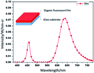
We measured the fluorescent film's emission light spectrum. The detailed parameters are as follows. The light source is a commercial 460 nm blue LED with a current of 1 A, a voltage of 5 V, a preheating light source time of 100 ms, and a light-source irradiation time of 75 ms. Fig. 1 shows the red light's emission light spectrum. After 50 s of spin coating and 30 min of baking at 45 °C, the fluorescent film is complete. The sample's structure appears in the upper left corner of Fig. 1. | ||
| Fig. 1 The spectrum of the fluorescent film's emission light under 460 nm blue LED, and the schematic of red fluorescent film. | ||
Table 3 shows the film quantum yield of using 10 ml of dichloromethane as a solvent with various amounts of fluorescent dyes. 5 mg of fluorescent dyes can produce a film quantum yield up to 84.8%.
| Dye weights/mg | Film quantum yield/% |
|---|---|
| 4.0 | 69.7 |
| 5.0 | 84.8 |
| 6.0 | 62.3 |
| 7.0 | 54.1 |
2.4 UV-encapsulation method
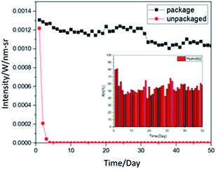
High humidity hinders the preservation of organic products, so we used a simple UV-encapsulation method to experiment the preservation effect. In a low-oxygen environment, we glued the two film samples together with UV glue and irradiated them with a 430 mW UV lamp for 10 seconds to cure the UV glue. We measured the light intensity daily and compared it to the film without encapsulation. The schematic diagram of the encapsulation is shown in Fig. 2.Fig. 3 compares the 2 month measurement chart with the encapsulated and unencapsulated sample film and the daily humidity changes. The lower right of Fig. 3 shows the humidity change over 50 days, with an average humidity of 55.1 (RH%). The encapsulated film is placed in the atmosphere, and its light intensity can be maintained at a certain value. The light intensity declines after 2 months. In comparison, without encapsulation, the film dropped to almost no fluorescent light within one week due to moisture in the atmosphere.
2.5 The relationship between basic group resonance and quantum yield
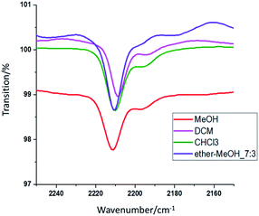
The molecule's polar part vibrates when it absorbs infrared light corresponding to its vibrational energy level. With this mechanism, the fluorescent dye molecule's structure can be measured with an FTIR, and the dye's characteristics can be analyzed via the specific structure. FTIR was used to measure the absorption position of the characteristic functional groups of the organic fluorescent dye DCJTB in various solutions. The FTIR spectra are shown in Fig. 4. Comparing the infrared spectrum and the dye's molecular structure reveals that the C![[triple bond, length as m-dash]](https://www.rsc.org/images/entities/char_e002.gif) N functional groups in the dye chromophore are in resonance positions in various solvents. Superimposing the peak positions of the C
N functional groups in the dye chromophore are in resonance positions in various solvents. Superimposing the peak positions of the C![[triple bond, length as m-dash]](https://www.rsc.org/images/entities/char_e002.gif) N functional groups in the four solvents reveals slight deviations in the peaks. The values are listed in Table 4. The displacement is calculated by subtracting the functional group resonance position (2196 cm−1) of the organic fluorescent dye in the powder state from the functional group resonance position in the organic fluorescent solution state.
N functional groups in the four solvents reveals slight deviations in the peaks. The values are listed in Table 4. The displacement is calculated by subtracting the functional group resonance position (2196 cm−1) of the organic fluorescent dye in the powder state from the functional group resonance position in the organic fluorescent solution state.
| Solvent | Peak/cm−1 | Displacement/cm−1 |
|---|---|---|
| a Displacement = peak_solvent − peak_DCJTB (2196 cm−1) | ||
| MeOH | 2211.4 | 15.4 |
Ether–MeOH_7![[thin space (1/6-em)]](https://www.rsc.org/images/entities/char_2009.gif) : :![[thin space (1/6-em)]](https://www.rsc.org/images/entities/char_2009.gif) 3 3 |
2210.6 | 14.6 |
| DCM | 2208.8 | 12.8 |
| CHCl3 | 2210.4 | 14.4 |
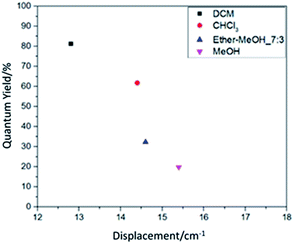
Comparing the quantum yield value in Table 1 and the displacement value in Table 4 reveals that they have good correspondence. It is further shown in Fig. 5 for the relation between resonance displacement of the functional group vs. its quantum yield under various solvents. The peaks of functional groups in the solution state dyes all shifted toward the longer wavelength. Among them, solvents with larger polarity have larger shifts and smaller quantum yield values. Solvents with smaller polarities have less displacement and larger quantum yield values, which can reach 81.3%. Thus, the dye chromophore's functional group is greatly affected by the solvent. The solution with a high polarity increased the molecule's chemical bond length and decreased the bond's force constant K, which reduces the frequency of stretching vibration and causes the shift in red absorption. The results reveal that the solution with the higher quantum yield value is brighter red, and it is very easy to dissolve the organic fluorescent dye. For solutions with lower quantum yield, the solution is dark red because the increase in solvent polarity decreases the energy of the chromophore π → π* transition, which leads to a shift of the absorption spectrum toward red and a decrease in quantum yield.
 | ||
| Fig. 5 The relation between resonance displacement of the functional group and the solution quantum yield. | ||
Although ether has extremely high solubility for fluorescent dyes and the solvent also presents a brighter red color, it cannot dissolve polymers. Therefore, it is mixed with alcohols to get better solubility for polymers. Comparing ether–MeOH_7![[thin space (1/6-em)]](https://www.rsc.org/images/entities/char_2009.gif) :
:![[thin space (1/6-em)]](https://www.rsc.org/images/entities/char_2009.gif) 3 with MeOH in Tables 1 and 4, it is found that the quantum yield of ether–MeOH_7
3 with MeOH in Tables 1 and 4, it is found that the quantum yield of ether–MeOH_7![[thin space (1/6-em)]](https://www.rsc.org/images/entities/char_2009.gif) :
:![[thin space (1/6-em)]](https://www.rsc.org/images/entities/char_2009.gif) 3 is higher, and the resonance displacement of the functional group is also smaller. In this study, we experiment on four solvents: MeOH, ether–MeOH_7
3 is higher, and the resonance displacement of the functional group is also smaller. In this study, we experiment on four solvents: MeOH, ether–MeOH_7![[thin space (1/6-em)]](https://www.rsc.org/images/entities/char_2009.gif) :
:![[thin space (1/6-em)]](https://www.rsc.org/images/entities/char_2009.gif) 3, DCM, and CHCl3. Among them, DCM gives the highest quantum yield and the smallest resonance displacement of the functional group.
3, DCM, and CHCl3. Among them, DCM gives the highest quantum yield and the smallest resonance displacement of the functional group.
3. Conclusions
Improving the quantum yield of rare-earth-free fluorescent films can help in developing the red color conversion layer and used in LED displays. We use no rare-earth elements to make red fluorescent film that can maintain a light intensity for 50 days in an environment with an average humidity of 55.1 (RH%) through a simple encapsulation method. We also tested the dye's characteristics in various solvents. The FTIR measurement of functional groups shows that the fluorescent dye DCJTB has a C![[triple bond, length as m-dash]](https://www.rsc.org/images/entities/char_e002.gif) N at a wavenumber of 2196 (cm−1) functional groups. Overlapping the positions of C
N at a wavenumber of 2196 (cm−1) functional groups. Overlapping the positions of C![[triple bond, length as m-dash]](https://www.rsc.org/images/entities/char_e002.gif) N functional groups measured in various solutions shows that the positions of functional groups will shift due to the solvent effect. A solution with high polarity increases the molecule's chemical bond length and decreases the bond's force constant K, so the stretching vibration frequency decreases and is inversely proportional to the measured quantum yield value. Therefore, to increase the quantum yield value, the resonance position of the functional group must be closer to the original organic fluorescent dyes. Finally, using dichloromethane with a strong polarity as the solvent of DCJTB can produce only 12.8 (cm−1) of the resonance displacement of the C
N functional groups measured in various solutions shows that the positions of functional groups will shift due to the solvent effect. A solution with high polarity increases the molecule's chemical bond length and decreases the bond's force constant K, so the stretching vibration frequency decreases and is inversely proportional to the measured quantum yield value. Therefore, to increase the quantum yield value, the resonance position of the functional group must be closer to the original organic fluorescent dyes. Finally, using dichloromethane with a strong polarity as the solvent of DCJTB can produce only 12.8 (cm−1) of the resonance displacement of the C![[triple bond, length as m-dash]](https://www.rsc.org/images/entities/char_e002.gif) N functional group with the quantum yield as high as 81.3% and a fluorescent film with a quantum yield as high as 84.8%.
N functional group with the quantum yield as high as 81.3% and a fluorescent film with a quantum yield as high as 84.8%.
Conflicts of interest
There are no conflicts to declare.Acknowledgements
This work was financially supported by the Ministry of Science and Technology of Taiwan with the contract numbers: MOST 110-2218-E-002-032-MBK. Authors thank Prof. C. S. Lin and Ms. Y. T. Lee of Instrumentation Center, National Taiwan University for FEG-SEM experiments.Notes and references
- E. F. Schubert and J. K. Kim, Science, 2005, 308(5726), 1274–1278 CrossRef CAS PubMed.
- B. D'andrade, Nat. Photonics, 2007, 1(1), 33–34 CrossRef.
- S. Tanabe, S. Fujita, S. Yoshihara, A. Sakamoto and S. Yamamoto, Proc. SPIE, 2005, 5941, 594112 CrossRef.
- H. C. Chen, K. J. Chen, C. H. Wang, C. C. Lin, C. C. Yeh, H. H. Tsai, M. H. Shih, H. C. Kuo and T. C. Lu, Nanoscale Res. Lett., 2012, 7(1), 1–5 CrossRef PubMed.
- T. R. Raman and Y. C. Ratnakaram, Opt. Mater., 2020, 99, 109515 CrossRef CAS.
- X. Gonze, Y. Jia, A. Miglio, S. Poncé and M. Mikami, in APS March Meeting Abstracts, 2019, vol. 2019, pp. F16–F005 Search PubMed.
- N. Narendran, Y. Gu, J. P. Freyssinier-Nova and Y. Zhu, Phys. Status Solidi A, 2005, 202(6), R60–R62 CrossRef CAS.
- G. Leising, U.S. Patent No. 8,227,273, U.S. Patent and Trademark Office, Washington, DC, 2012.
- Y. Feng, Y. P. Tong, F. Xie and F. L. Liao, Guangzhou Chem. Ind., 2019, 47(10), 69–71 Search PubMed.
- L. Kong, L. Qiao, Q. Y. Wei, M. Y. Zhao, Y. Y. Liu, W. S. Wang and H. H. Yu, J. Synth. Cryst., 2019, 48(4), 616–620 CAS.
- M. Yang, S. Long, Y. Zhu, H. Ma, S. Lin, J. Quan and B. Wang, Ceram. Int., 2021, 47(2), 1970–1975 CrossRef CAS.
- Q. Wu, Y. Xie, F. She, Q. Zhao, J. Ding and J. Zhou, J. Rare Earths, 2021, 39(9), 1040–1048 CrossRef CAS.
- T. R. Raman and Y. C. Ratnakaram, Opt. Mater., 2020, 99, 109515 CrossRef CAS.
- P. Li-Bing, J. Foshan Univ., Nat. Sci. Ed., 2019,(3), 23–26 Search PubMed.
- C. W. Tang and S. A. VanSlyke, Appl. Phys. Lett., 1987, 51(12), 913–915 CrossRef CAS.
- A. F. Rausch, M. E. Thompson and H. Yersin, J. Phys. Chem. A, 2009, 113(20), 5927–5932 CrossRef CAS.
- W. J. Finkenzeller, T. Hofbeck, M. E. Thompson and H. Yersin, Inorg. Chem., 2007, 46(12), 5076–5083 CrossRef CAS PubMed.
- S. Y. Kim, J. H. Kim, Y. Ha, S. H. Lee, J. H. Seo and Y. K. Kim, Curr. Appl. Phys., 2007, 7(4), 380–383 CrossRef.
- D. Litvinov, D. Gerthsen, A. Rosenauer, H. Preis, E. Kurtz and C. Klingshirn, Phys. Status Solidi B, 2001, 224(1), 147–151 CrossRef CAS.
- K. H. Drexhage and F. P. Schafer, Topics in applied physics: dye lasers, 2020, vol. I, p. 144 Search PubMed.
- H. Gold, in The chemistry a/synthetic dyes, ed. K. Venkataraman, C. W. Tang and S. A. VanSlyke, 2020, vol. 5, p. 535 Search PubMed.
- G. Belardi, N. Ippolito, L. Piga and M. Serracino, Thermochim. Acta, 2014, 591, 22–30 CrossRef CAS.
- G. R. Lumpkin, K. L. Smith and M. G. Blackford, J. Nucl. Mater., 1995, 224(1), 31–42 CrossRef CAS.
- R. Z. Rebello, M. T. W. D. C. Lima, L. H. Yamane and R. R. Siman, Conserv. Recycl., 2020, 153, 104557 CrossRef.
- S. Reineke, F. Lindner, G. Schwartz, N. Seidler, K. Walzer, B. Lüssem and K. Leo, Nature, 2009, 459(7244), 234–238 CrossRef CAS PubMed.
- J. H. Burroughes, D. D. Bradley, A. R. Brown, R. N. Marks, K. Mackay, R. H. Friend, P. L. Burns and A. B. Holmes, nature, 1990, 347(6293), 539–541 CrossRef CAS.
- M. A. Baldo, D. F. O'Brien, Y. You, A. Shoustikov, S. Sibley, M. E. Thompson and S. R. Forrest, Nature, 1998, 395(6698), 151–154 CrossRef CAS.
- J. Frischeisen, D. Yokoyama, C. Adachi and W. Brütting, Appl. Phys. Lett., 2010, 96(7), 29 CrossRef.
- M. Flämmich, M. C. Gather, N. Danz, D. Michaelis, A. H. Bräuer, K. Meerholz and A. Tünnermann, Org. Electron., 2010, 11(6), 1039–1046 CrossRef.
- G. Zhou, W. Y. Wong, B. Yao, Z. Xie and L. Wang, Angew. Chem., Int. Ed., 2007, 46(7), 1149–1151 CrossRef CAS PubMed.
- C. Jiang, W. Yang, J. Peng, S. Xiao and Y. Cao, Adv. Mater., 2004, 16(6), 537–541 CrossRef CAS.
- H. Sirringhaus, N. Tessler and R. H. Friend, Science, 1998, 280(5370), 1741–1744 CrossRef CAS PubMed.
- K. S. M. Tong, Solution-Processed Low-Cost Approaches for High-Efficiency Organic Light Emitting Diodes Substrates, University of California, Los Angeles, 2018 Search PubMed.
- H. V. Han, H. Y. Lin, C. C. Lin, W. C. Chong, J. R. Li, K. J. Chen, P. Yu, T. M. Chen, H. M. Chen, K. M. Lau and H. C. Kuo, Opt. Express, 2015, 23(25), 32504–32515 CrossRef CAS PubMed.
- F. Templier, J. Bernard, S. Caplet, A. Bédoin and H. Haas, Proc. SPIE, 2019, 10918, 109181Q Search PubMed.
| This journal is © The Royal Society of Chemistry 2021 |


