 Open Access Article
Phase separation of ternary epoxy/PEI blends with higher molecular weight of tertiary component polysiloxane
Jia-ting Wu,
Wei-zhen Li*,
Shu-long Wang and
Wen-jun Gan *
*
Shanghai University of Engineering Science, College of Chemistry and Chemical Engineering, 333 Longteng Road, Shanghai 201620, People's Republic of China. E-mail: wjgan@sues.edu.cn
First published on 23rd November 2021
Abstract
A tertiary component with higher molecular weight of epoxy terminated polysiloxane (DMS-E11) was incorporated into the diglycidyl ether of bisphenol-A (DGEBA)/thermoplastic polyetherimide (PEI) blends. In this ternary DGEBA/PEI/DMS-E11 system, 25 or 30 wt% PEI and no more than 20 wt% DMS-E11 were used to ensure the formation of a continuous PEI-rich phase via reaction induced phase separation for optimum mechanical properties of blends. The results of morphology monitoring by OM and TRLS indicated that the addition of DMS-E11 could accelerate phase separation of DGEBA/PEI. Obvious differences were observed by SEM/EDS in the final morphologies of the blends. DMS-E11 localized in the PEI-rich phase continuously while it separated with DGEBA into spherical particles in the DGEBA-rich phase. DMA measurements found that the storage modulus and Tg decreased with DMS-E11 content but were compensated partly by the presence of PEI. The results of tensile tests confirmed the synergistic strengthening for epoxy resin from PEI and DMS-E11.
Introduction
Epoxy resins, as one of the most important types of thermosetting polymer, are widely used in coatings, adhesives, electric/electronic materials, and the matrices for high-performance composites due to their low curing shrinkage, excellent processability and mechanical and electrical properties, and chemical and thermal stability.1–3 However, their highly cross-linked three-dimensional networks make them inherently brittle when fully cured. Therefore, it is necessary to improve their toughness for potential application.4–7Over the past a few decades, toughening epoxy and maintaining its high strength at the same time have always been an important subject.8–10 A practical approach to toughen epoxy resins is to use thermoplastics with high glass transition temperature, excellent thermal stability and toughness, such as polysulfone (PSF),11–13 poly(ether sulfone) (PES),14–16 polyimides (PI)17–19 and poly(ether imides) (PEI).20–22 PEI with excellent mechanical properties can effectively improve the toughness of epoxy resin without sacrificing other properties of epoxy resin and has been widely used as the modifier of epoxy resin.23,24 For a typical thermoplastics-modified system, phase separation will occur during the curing reaction of epoxy resin and the blend separates into two phases. Since the properties of the materials are determined by continuous phase in the final morphologies and it has been widely accepted that the effective improvement in toughness will be obtained only with the co-continuous or phase inversion structure.25,26
Polysiloxanes have high flexibility, low glass transition temperature, and excellent thermal and oxidative stability, as well as low surface tension, suggesting they would be suitable to toughen epoxy resins.27,28 However, polysiloxanes are rarely used as a toughening agent because of the poor compatibility between soft segments of polysiloxane and carbon-based epoxy resin.29 Various methods have been developed to improve the miscibility of polysiloxanes with epoxy resins, including using silane coupling agents,30 introduction of functional groups, such as hydroxyl,31 amino,32–34 epoxy35–38 and carboxyl group.39 On the other hand, polysiloxanes can significantly compromise the storage modulus and glass transition temperature (Tg) of epoxy resins.40,41
The introduction of both PEI and polysiloxane might effectively balance the decrease of Tg and toughen epoxy resin synergistically. Our previous works investigated the miscibility between DGEBA and epoxy terminated siloxane with lower molecular weight (DMS-E09),38 and the effects of DMS-E09 on the phase separation and properties of blends DGEBA/PEI.42 The molecular weight of DMS-E09 is 362 and its corresponding monomer has only one –Si–O–Si– unit. It was miscible with DGEBA to some extent and entered mainly into DGEBA-rich phase in ternary blends DGWBA/PEI/DMS-E09. In this work, epoxy terminated polysiloxane (DMS-E11) with higher molecular weight of 500–600 and 4–5 –Si–O–Si– units was taken into account. For every blend, morphology evolution was monitored by optical microscopy (OM) and time-resolved light scattering (TRLS). The final morphology was observed by scanning electron microscopy (SEM/EDS). The dynamic mechanical behavior and tensile property were measured by dynamic mechanical analysis (DMA) and tension machine. The miscibility of DMS-E11 with DGEBA or PEI would affect the phase separation between DGEBA and PEI, and resultant properties. It was expected to control the properties of these ternary blends DGEBA/PEI/DMS-E11 for extending applications via tuning the length of –Si–O–Si– units in tertiary component epoxy terminated siloxane.
Materials and methods
Materials
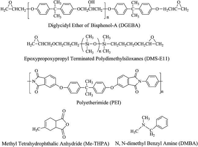
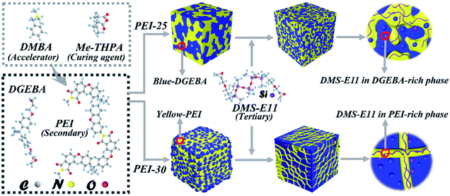
Diglycidyl ether of bisphenol-A (DGEBA, DER331) with the epoxide equivalent weight of 182–192 g eq−1 was supplied from Dow Chemical Corporation, USA. Epoxypropoxypropyl terminated polydimethylsiloxane (DMS-E11, Mn = 500–600) was purchased from Gelest Incorporation, USA. The polyetherimide, PEI (Ultem 1000), was supplied by SABIC's Innovative Plastics, Saudi Arabia. The curing agent methyl tetrahydrophthalic anhydride (Me-THPA) and the accelerator N,N-dimethyl benzyl amine (DMBA) were obtained from Sinopharm Chemical Reagent Co., Ltd, China. All reagents were used as supplied without further purification. Their chemical structures are shown in Scheme 1.Sample preparation
Epoxy blends containing different ratio of PEI and DMS-E11 were prepared through following processes. Firstly, PEI was added to DGEBA under stirring at 150 °C for 4 h until PEI was dissolved completely. Then, DMS-E11 was added to the blend DGEBA/PEI. After that, stoichiometric curing agent Me-THPA with accelerator BDMA were added to the above ternary mixture with stirring at 120 °C for 3 min. Part of the mixture was poured into square molds and cured at 150 °C for 5 h and post cured at 200 °C for 2 h. The remainder was stored in the refrigerator to avoid further curing reaction for the sequential OM and TRLS tests. Neat DGEBA and binary blends were prepared via the same processes for comparison. The binary and ternary system were designated as PEI-X, E11-Y and PEI-X–E11-Y (X = 25 or 30 wt%, Y = 5, 10, 15 or 20 wt%). The compositions and designation of the blends are listed in Table 1.| Sample | DGEBA | DMS-E11 | PEI |
|---|---|---|---|
| a pbw: parts by weight of epoxy resin. | |||
| Neat DGEBA | 100 | 0 | 0 |
| PEI-X | 100 | 0 | X (25 or 30) |
| E11-Y | 100-Y | Y (5,10,15 or 20) | 0 |
| PEI-X–E11-Y | 100-Y | Y (5,10,15 or 20) | X (25 or 30) |
Measurements
The morphology evolution via phase separation was observed using optical microscope (OM, Shanghai Wei Tu Optics & Electron Technology Co., Ltd, China) equipped with a heating stage. The uncured blends sandwiched between two glass slides (about 10 mm × 10 mm) were melt pressed and then cured isothermally at 150 °C on a heating stage.The phase separation processes were monitored by a self-made time-resolved light scattering (TRLS) instrument with a temperature controlled hot chamber. The samples for TRLS observation were sandwiched between two glass slides. The data were recorded at appropriate time intervals.
The morphologies were observed by scanning electron microscopy (SEM, Hitachi S-3400, Japan) at an acceleration voltage of 5 kV. The specimens were cryogenically fractured in liquid nitrogen, followed by coating with thin layers of gold. The energy dispersive spectroscopy (EDS) was used to determine the localization and distribution of Si and C elements on the fractured surface.
The thermomechanical properties of blends were measured by dynamic mechanical analysis (DMA, TA Q800, USA) using a one-point bending configuration. The testing was performed at 1 Hz with a heating rate of 3 °C min−1 from 30 to 250 °C. The specimen dimensions for the DMA measurement were 50 × 10 × 2 mm3.
Mechanical properties of the post cured blends were measured at room temperature on an electronic universal testing machine (CZ-8000, Zhong Zhi Testing Machines Co., Ltd, China).
Results and discussion
Effect of DMS-E11 on the phase separation of DGEBA/PEI-25 co-continuous system
The phase separation processes of the ternary system DGEBA/PEI-25/DMS-E11 with different content of DMS-E11 were monitored by OM. As the DMS-E11 content increased from 0 to 20 wt%, the phase separation began at about 156 s, 124 s, 102 s, 83 s and 57 s, respectively. The introduction of polysiloxane would decrease the miscibility between DGEBA and PEI. Therefore, the addition of tertiary component DMS-E11 could accelerate the occurrence of phase separation between DGEBA and PEI, and the phase separation happened earlier. Final morphologies were shown in Fig. 1. The bright regions (i) refer to the DGEBA-rich phase, and the dark regions are corresponding to the PEI-rich phase. The periodic distances are in the range of 100–200 μm. When the content of DMS-E11 reaches 15 wt% and 20 wt% (Fig. 1d and e), the PEI-rich phases become thinner and their morphologies incline to be phase inversion structure with PEI-rich phase as continuous phase.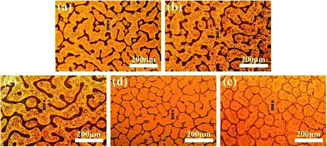 | ||
| Fig. 1 Final morphology for the ternary DGEBA/PEI-25/DMS-E11 system with different content of DMS-E11, (a) PEI-25, (b) PEI-25–E11-05, (c) PEI-25–E11-10, (d) PEI-25–E11-15, and (e) PEI-25–E11-20. | ||
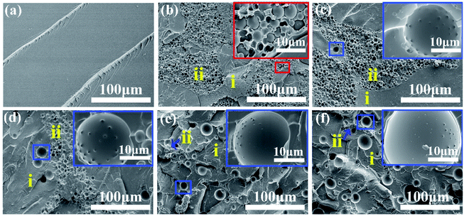
Fig. 2 shows the SEM images of the fracture surface of the ternary DGEBA/PEI-25/DMS-E11 system with different content of DMS-E11. Siloxane-rich phase is invisible by OM but can be observed in the SEM pictures. Therefore, these pictures are somewhat different with those of OM. The unmodified neat DGEBA (Fig. 2a) displays a typical brittle fracture. Both PEI-rich phase and DGEBA-rich phase in a co-continuous structure are observed in the binary blend PEI-25 (Fig. 2b). Here the dark regions (i) correspond to the DGEBA-rich phase, whereas the bright regions (ii) correspond to the PEI-rich phase. Similar morphologies are able to maintain unless DMS-E11 content is more than 10 wt% (Fig. 2b–d). At the same time, DGEBA-rich particles of 5–10 μm can be found in PEI-rich phases of the blend PEI-25 (inset in the red box). With the increase of DMS-E11 content, bigger particles appear near or in PEI-rich phase, making the PEI-rich phases splitting into pieces. These variety of particles are thought to be DMS-E11-rich phase, and they increase in numbers and size with DMS-E11 content, from 15 μm to 25 μm in diameter (inset in the blue boxes of Fig. 2c–f). As seen in the micrographs of Fig. 2e and f, blends PEI-25–E11-15 and PEI-25–E11-20 differ remarkably from others in terms of microstructure and particle size. A co-continuous morphology with inter-connected PEI-rich phases is hardly observed in both cases. Instead, indistinct phase inversion morphologies are observed with bigger particles dispersing in it. It is probably due to the introduction of DMS-E11 which reduces the viscosity of the blends and makes the PEI chains easy to disentangle into thinner appearance. Another interesting founding is that there are protrusions or antennae distributing regularly on the surface of spherical DMS-E11-rich phase in blends with DMS-E11, unlike lower molecular weight of DMS-E09 with only one –Si–O–Si– unit which had smooth appearance. When the DMS-E11 content increases, the protrusions become less obvious on the increasing size of DMS-E11-rich phase. These protrusions are presumably DGEBA-rich phase, double even triple phase separation might have occurred for these ternary blends.
Effect of DMS-E11 on the phase separation of DGEBA/PEI-30 inverted system
Similarly, the phase separation processes of the ternary DGEBA/PEI-30/DMS-E11 system were tracked by OM and the final morphologies closely resemble each other as shown in Fig. 3. With the addition of tertiary component DMS-E11, the onset time of phase separation became earlier. With the increase of DMS-E11 content from 0 wt% to 20 wt%, phase separations took place at about 220 s, 183 s, 165 s, 144 s and 119 s, respectively. It implies that the miscibility between DGEBA and PEI decreases with the addition of DMS-E11.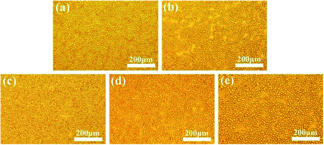 | ||
| Fig. 3 Final morphology for the ternary DGEBA/PEI-30/DMS-E11 system with different content of DMS-E11, (a) PEI-30, (b) PEI-30–E11-05, (c) PEI-30–E11-10, (d) PEI-30–E11-15, and (e) PEI-30–E11-20. | ||
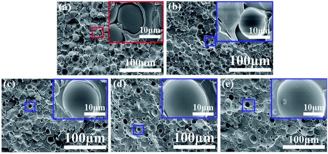
The fully cured ternary blends DGEBA/PEI/DMS-E11 with 30 wt% PEI and different DMS-E11 were observed by SEM as shown in Fig. 4. These pictures are also slightly different with those of OM due to the siloxane-rich phases are also invisible by OM but can be observed in the SEM images. For binary blend PEI-30, a distinct phase inversion structure can be seen with spherical DGEBA-rich particles of about 5–20 μm dispersing uniformly in the continuous PEI-rich matrix (Fig. 4a). For blends with 15 wt%, 20 wt% of DMS-E11 (Fig. 4d and e), it seems that the ordering of phase inversion structure is disrupted or even destroyed. It is quite different with the results from DMS-E09 blends, which the continuous PEI-rich phases still remain distinctly.42 Moreover, as shown in the magnified insets in Fig. 4b–e, spherical particles of 15–25 μm are found in DGEBA-rich phase and increases with DMS-E11 content, which are also regarded as DMS-E11-rich phase. Similarly, they increase in numbers and size with DMS-E11 content, from 15 μm to 25 μm in diameter (inset in the blue boxes of Fig. 4b–e). Interestingly, the protrusions or antennae are not seen at the surfaces of these DMS-E11-rich particles in all blends. Oppositely, these particles have quite smoothing appearance.
SEM/EDS was subsequently used to figure out the localization of the tertiary component DMS-E11. Fig. 5 shows higher magnification SEM images and their corresponding elemental mapping of C (red signals of 5a1, b1, c1) and Si (green signals of 5a2, b2, c2) in blends PEI-25–E11-10 (PEI-rich phase), PEI-30–E11-20. It can be seen that the particles give red element C signals while the continuous networks show clear green element Si signals. It illustrates that the tertiary component DMS-E11 enters into both DGEBA-rich phase and PEI-rich phase for co-continuous DGEBA/PEI-25 and inverted DGEBA/PEI-30 systems. However, DMS-E11 localizes in PEI-rich phase continuously (Fig. 5a2 and b2) while it separates with DGEBA into spherical particles in DGEBA-rich phase (Fig. 5c2). It suggests that the tertiary component DMS-E11 is more miscible with PEI and become a part of the continuous network together with PEI.
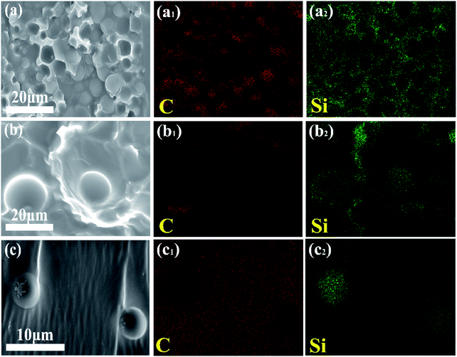 | ||
| Fig. 5 SEM/EDS images of fractured surface of (a) PEI-25–E11-10 (PEI-rich phase), (b) PEI-30–E11-20, (c) E11-20. | ||
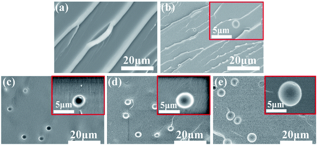
To confirm the above speculation of miscibility between DGEBA and DMS-E11, binary blends of DGEBA with different content DMS-E11 were prepared and the microstructures were shown in Fig. 6. The neat DGEBA (Fig. 6a) exhibits a homogeneous structure and displays a typical brittle fracture. For blends with DMS-E11, spherical particles appear and disperse uniformly in the DGEBA-rich matrix (Fig. 6b–e). With the increase of DMS-E11 content, particles increase in number and diameter from 2 μm to 5 μm gradually. In comparison of neat DGEBA with blend E11-20, the elemental mapping of C and Si of SEM/EDS (Fig. 5c2) clearly show that the element Si signals are corresponding to the particles perfectly. It indicates that phase separation has occurred between the two co-cured epoxy resins (DGEBA and DMS-E11) and the resultant dispersing particles are DMS-E11-rich phase. These observations are consistent with the results obtained from the above ternary system. This may also confirm that the spherical domains in DGEBA-rich phase should be DMS-E11-rich phase. As for the regularly happened protrusion, the initial consideration of DGEBA-rich phase should be plausible.
According to the selective localization of DMS-E11 during the curing reaction for DGEBA/PEI system, the schematic diagram of phase separation for blends DGEBA/PEI/DMS-E11 with 25 wt% PEI or 30 wt% PEI are proposed in Scheme 2. For both binary co-continuous blend PEI-25 and inverted blend PEI-30, original morphologies were not able to maintain when the tertiary component DMS-E11 was introduced into these systems. DMS-E11 enters into both DGEBA-rich phase and PEI-rich phase. The difference was that DMS-E11 localized in PEI-rich phase continuously while it separated with DGEBA into spherical particles in DGEBA-rich phase.
Phase separation monitored by TRLS
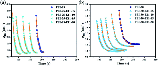
To further investigate the effect of higher molecular tertiary component DMS-E11 on the phase separation of blends DGEBA and PEI, the isothermal phase separation processes at 150 °C of all blends were monitored in situ by TRLS. Fig. 7 shows two typical examples of the change in the scattering profile with time (t) for blends PEI-25–E11-10 (Fig. 7a) and PEI-30–E11-10 (Fig. 7b).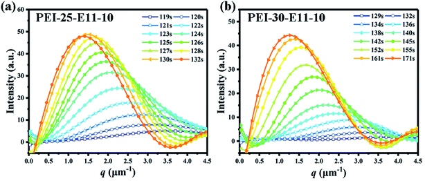 | ||
| Fig. 7 The scattered light intensity is a function of time and scattering vector for blends cured isothermally at 150 °C, (a) PEI-25–E11-10 and (b) PEI-30–E11-10. | ||
The scattered light intensity (I) is a function of time (t) and scattering vector (q), the latter is defined by formula (1).
 | (1) |
| Λm = 2π/qm | (2) |
Moreover, the evolution of qm with t for every blend follows the Maxwell-type relaxation equation (formula (3)). It indicates that the phase separation of all blends follows the viscoelastic phase separation behavior. Therefore, the introduction of higher molecular weight tertiary component DMS-E11 and increase of siloxane segments (in comparison with DMS-E09 systems)42 have not changed the mechanism of phase separation between DGEBA and PEI.
 | (3) |
As shown in Fig. 8a and b, the final qm values decreases from 0.84 to 0.75 μm−1 with the increase of DMS-E11 content for the co-continuous DGEBA/PEI-25 system, and the corresponding periodic distance increases from 7.5 to 8.4 μm (calculated by formula (2)). For the inversion DGEBA/PEI-30 system, the final qm value decreases from 1.58 to 0.95 μm−1, and the corresponding periodic distance increases from 4.0 μm to 6.6 μm (calculated by formula (2)), which are consistent with corresponding spherical DGEBA-rich phase from SEM pictures of Fig. 2 and 4 respectively. Meanwhile, it can be seen in Fig. 8a and b that the onset time of phase separation for all blends begins earlier with the increase of DMS-E11 content. This indicates that DMS-E11 can accelerate the occurrence of phase separation.
In comparison with previous work with DMS-E09,42 it is seen that DGEBA/PEI/DMS-E11 are more immiscible. For example, the phase separation of blends PEI-25–E11-10 and PEI-30–E11-10 took place phase separation at 134 s, 152 s, respectively. While the onset times of phase separation monitored also by TRLS for blends PEI-25–E09-10 and PEI-30–E09-10 were 287 s, 358 s, respectively.
Thermomechanical behavior of ternary blends DGEBA/PEI/DMS-E11
Dynamic mechanical analysis is an efficient tool to measure the thermomechanical properties, crosslinking network structure, even the possible morphology of multiple component blends. Fig. 9a and c show the curves of storage modulus E′ versus temperature and Fig. 9b and d show the loss factor (tan![[thin space (1/6-em)]](https://www.rsc.org/images/entities/char_2009.gif) δ) against temperature for all ternary blends DGEBA/PEI/DMS-E11 with different contents of PEI and DMS-E11. The storage modulus E′, the glass transition temperature (Tg), and the amplitudes of the tan
δ) against temperature for all ternary blends DGEBA/PEI/DMS-E11 with different contents of PEI and DMS-E11. The storage modulus E′, the glass transition temperature (Tg), and the amplitudes of the tan![[thin space (1/6-em)]](https://www.rsc.org/images/entities/char_2009.gif) δ peak (h) are summarized.
δ peak (h) are summarized.
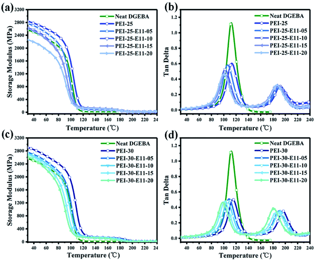 | ||
Fig. 9 DMA results for ternary blends DGEBA/PEI/DMS-E11 with different content of PEI and DMS-E11, (a and c) storage modulus versus temperature and (b and d) tan![[thin space (1/6-em)]](https://www.rsc.org/images/entities/char_2009.gif) δ versus temperature. δ versus temperature. | ||
As shown in Fig. 9a, for co-continuous DGEBA/PEI-25/DMS-E11 system, the storage modulus increases from 2565 MPa of neat DGEBA to 2837 MPa of the binary blend PEI-25. Then, the storage modulus decreases gradually from 2837 MPa to 2262 MPa with the increase of DMS-E11 content from 5 wt% to 20 wt%. However, the storage modulus is still higher than that of neat DGEBA provided the DMS-E11 content is no more than 15 wt%.
As shown in Fig. 9c, all ternary blends DGEBA/PEI-30/DMS-E11 with inversion morphology have higher storage modulus (E′) than neat DGEBA. The addition of 30 wt% PEI into epoxy leads to an increase in storage modulus from 2565 MPa of neat DGEBA to 2906 MPa of the binary blend PEI-30. The storage modulus then drops monotonically with the increase of tertiary component DMS-E11 to 2630 MPa of the blend PEI-30–E11-20. Even with 20 wt% DMS-E11, the ternary blend still has higher storage modulus than that of neat DGEBA. In other words, it may indicate that the decrease caused by the flexible siloxane fragments of the tertiary component DMS-E11 can be compensated partly by the presence of 25 wt% or 30 wt% PEI.
The glass transition temperature (Tg) is a crucial property for the potential applications of epoxy blends, which is closely related to the thermo-mechanical stability of epoxy blends. In general, the peak temperature of tan![[thin space (1/6-em)]](https://www.rsc.org/images/entities/char_2009.gif) δ is taken as the Tg of a polymer. As shown in Fig. 9b and d and Table 2, the two α relaxations in the range from room temperature to 240 °C illustrate the occurrence of the phase separation between DGEBA and PEI, corresponding to the DGEBA-rich network (Tg1) and the PEI-rich phase (Tg2), respectively. In 25 wt% PEI system, the Tg1 of DGEBA-rich phase decreases monotonically from 113 °C of the binary blend PEI-25 to 99 °C of the ternary blend PEI-25–E11-20 and Tg2 decreases from 192 °C to 186 °C. In 30 wt% PEI system, the Tg1 of epoxy-rich phase decreases from 114 °C to 98 °C and Tg2 decreases from 195 °C to 182 °C. Tg1 is reduced because DMS-E11 with flexible siloxane chains enter the crosslinking network of DGEBA, while the reduction of Tg2 is due to two epoxy oligomers (DGEBA and DMS-E11) enter the PEI-rich phase. In comparison with the two system, the effect of the introduction of tertiary component DMS-E11 on the Tg2 corresponding to PEI-rich phase is more remarkable since DMS-E11 favours localization in PEI-rich phase. This makes an obvious difference from the results of co-continuous system with DMS-E09, which is more miscible with DGEBA than PEI and lead to a significant reduction of Tg1 value corresponding to DGEBA-rich phase.42
δ is taken as the Tg of a polymer. As shown in Fig. 9b and d and Table 2, the two α relaxations in the range from room temperature to 240 °C illustrate the occurrence of the phase separation between DGEBA and PEI, corresponding to the DGEBA-rich network (Tg1) and the PEI-rich phase (Tg2), respectively. In 25 wt% PEI system, the Tg1 of DGEBA-rich phase decreases monotonically from 113 °C of the binary blend PEI-25 to 99 °C of the ternary blend PEI-25–E11-20 and Tg2 decreases from 192 °C to 186 °C. In 30 wt% PEI system, the Tg1 of epoxy-rich phase decreases from 114 °C to 98 °C and Tg2 decreases from 195 °C to 182 °C. Tg1 is reduced because DMS-E11 with flexible siloxane chains enter the crosslinking network of DGEBA, while the reduction of Tg2 is due to two epoxy oligomers (DGEBA and DMS-E11) enter the PEI-rich phase. In comparison with the two system, the effect of the introduction of tertiary component DMS-E11 on the Tg2 corresponding to PEI-rich phase is more remarkable since DMS-E11 favours localization in PEI-rich phase. This makes an obvious difference from the results of co-continuous system with DMS-E09, which is more miscible with DGEBA than PEI and lead to a significant reduction of Tg1 value corresponding to DGEBA-rich phase.42
| Sample | E′a (MPa) | Tg1b (°C) | Tg2b (°C) | h1c | h2c | h2/h1 |
|---|---|---|---|---|---|---|
a The storage modulus (E′) was taken at 30 °C.b The Tg was determined by the tan![[thin space (1/6-em)]](https://www.rsc.org/images/entities/char_2009.gif) δ peak temperature.c The amplitudes of the tan δ peak temperature.c The amplitudes of the tan![[thin space (1/6-em)]](https://www.rsc.org/images/entities/char_2009.gif) δ peak. δ peak. |
||||||
| Neat DGEBA | 2565 | 112 | — | 1.13 | — | — |
| PEI-25 | 2837 | 113 | 192 | 0.60 | 0.31 | 0.52 |
| PEI-25–E11-05 | 2763 | 107 | 190 | 0.58 | 0.29 | 0.50 |
| PEI-25–E11-10 | 2630 | 103 | 188 | 0.52 | 0.31 | 0.60 |
| PEI-25–E11-15 | 2611 | 101 | 187 | 0.47 | 0.32 | 0.67 |
| PEI-25–E11-20 | 2262 | 99 | 186 | 0.47 | 0.32 | 0.67 |
| PEI-30 | 2906 | 114 | 195 | 0.50 | 0.35 | 0.70 |
| PEI-30–E11-05 | 2756 | 108 | 190 | 0.50 | 0.35 | 0.70 |
| PEI-30–E11-10 | 2707 | 105 | 189 | 0.48 | 0.34 | 0.71 |
| PEI-30–E11-15 | 2694 | 101 | 186 | 0.47 | 0.34 | 0.72 |
| PEI-30–E11-20 | 2630 | 98 | 182 | 0.46 | 0.37 | 0.80 |
Furthermore, the ratio of amplitude (h2/h1) from the tan![[thin space (1/6-em)]](https://www.rsc.org/images/entities/char_2009.gif) δ curve can predict qualitatively the kind of morphology generated for ternary blends DGEBA/PEI/DMS-E11.45,46 For the ternary DGEBA/PEI-25/DMS-E11 system, the ratios of h2/h1 are around 0.5–0.6 (Table 2) when the content of DMS-11 is lower than 10 wt%. These values should be corresponding to the morphology of co-continuous structure, which are consistent with the morphologies observed by OM and SEM. For blends PEI-25–E11-15 and PEI-25–E11-20, however, both ratios of h2/h1 are 0.67, corresponding to the morphology of the inverted structure which are consistent with what have been observed by OM and SEM. For the ternary DGEBA/PEI-30/DMS-E11 system, the ratios of h2/h1 are all around 0.7–0.8 (Table 2). These values reveal the morphology of the inverted structure which are also in accord with the results of OM and SEM.
δ curve can predict qualitatively the kind of morphology generated for ternary blends DGEBA/PEI/DMS-E11.45,46 For the ternary DGEBA/PEI-25/DMS-E11 system, the ratios of h2/h1 are around 0.5–0.6 (Table 2) when the content of DMS-11 is lower than 10 wt%. These values should be corresponding to the morphology of co-continuous structure, which are consistent with the morphologies observed by OM and SEM. For blends PEI-25–E11-15 and PEI-25–E11-20, however, both ratios of h2/h1 are 0.67, corresponding to the morphology of the inverted structure which are consistent with what have been observed by OM and SEM. For the ternary DGEBA/PEI-30/DMS-E11 system, the ratios of h2/h1 are all around 0.7–0.8 (Table 2). These values reveal the morphology of the inverted structure which are also in accord with the results of OM and SEM.
Mechanical properties of ternary blends DGEBA/PEI/DMS-E11
In order to understand the influence of higher molecular weight tertiary component DMS-E11 on the mechanical properties of DGEBA/PEI system, tensile test was also performed. The tensile properties with different content of PEI and DMS-E11 were measured and the results were presented in Fig. 10 and Table 3.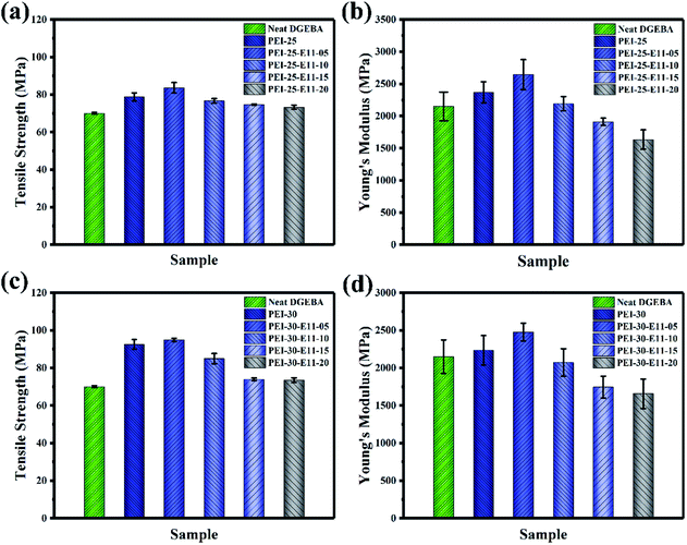 | ||
| Fig. 10 Tensile properties for ternary blends DGEBA/PEI/DMS-E11 with different content of PEI and DMS-E11, (a and c) tensile strength and (b and d) Young's modulus. | ||
| Sample | Tensile strength (MPa) | Young's modulus (MPa) |
|---|---|---|
| Neat DGEBA | 70.6 | 2150 |
| PEI-25 | 78.8 | 2369 |
| PEI-25–E11-05 | 83.7 | 2643 |
| PEI-25–E11-10 | 76.7 | 2192 |
| PEI-25–E11-15 | 74.8 | 1912 |
| PEI-25–E11-20 | 73.3 | 1635 |
| PEI-30 | 92.5 | 2235 |
| PEI-30–E11-05 | 94.9 | 2477 |
| PEI-30–E11-10 | 85.0 | 2072 |
| PEI-30–E11-15 | 73.9 | 1746 |
| PEI-30–E11-20 | 73.5 | 1657 |
For blend PEI-25, the tensile strength and Young's modulus reach to 78.8 MPa and 2369 MPa, respectively. Compared with 70.6 MPa and 2150 MPa of the neat DGEBA, the mechanical properties are improved due to the addition of PEI with excellent mechanical properties and the formation of co-continuous structure. Subsequently, the tensile strength and Young's modulus of the blend is remarkably improved by the addition of 5 wt% DMS-E11 for blend PEI-25–E11-05 then drop with the increase content of DMS-E11. The introduction of tertiary component DMS-E11 with soft siloxane segments into the epoxy network dissipates the energy at the fracture of the propagation surfaces, resulting in an increase of tensile strength.47,48 Meanwhile, the addition of 5 wt% DMS-E11 has little effect on the formation of co-continuous morphology, DMS-E11 and PEI can synergistically strengthen the epoxy resin. However, the tensile strength decreases with the increase of DMS-E11 content, which may attribute mainly to the flexible –Si–O–Si– segments in DMS-E11. In addition, the addition of higher molecular weight DMS-E11 will decrease the crosslinking density of DGEBA networks, and hence result in the reduction of tensile strength.49,50 When the content of DMS-E11 increases, the effect of soft segments in DMS-E11 will be more important. In comparison with the neat DGEBA, however, the tensile properties of the ternary DGEBA/PEI-25/DMS-E11 system exhibits better mechanical properties. It indicates that the decrease caused by the flexible siloxane segments can be saved partly by the presence of PEI with excellent mechanical properties.
Similarly, the addition of 30 wt% PEI for the binary blend PEI-30 leads to an increase in Young's modulus as shown in Fig. 10c and d. It can be found that both tensile strength and Young's modulus of the ternary DGEBA/PEI-30/DMS-E11 system are the optimum when the content of DMS-E11 is 5 wt%. Tensile strength and Young's modulus will then decrease with the increase of tertiary component DMS-E11 content.
Conclusions
In this work, tertiary component epoxy functional siloxane DMS-E11 with higher molecular weight was incorporated into the DGEBA/PEI modified blend. The effects of this tertiary component on the phase separation, morphology and properties of ternary blends were investigated. The results of morphology monitoring found that the addition of DMS-E11 could accelerate phase separation of DGEBA/PEI, indicating that the presence of DMS-E11 made the miscibility between DGEBA and PEI decrease. Observation of the final morphologies for different blends with SEM/EDS found that DMS-E11 localized in PEI-rich phase continuously while it separated with DGEBA into spherical particles in DGEBA-rich phase. Protrusion on the spherical DMS-E11-rich phase in co-continuous system might imply the occurrence of double even triple phase separation. TRLS monitoring confirmed that the introduction of higher molecular weight didn't affect viscoelastic spinodal phase separation mechanism.The storage modulus and glass transition temperatures for the blends with different content of DMS-E11 were measured by DMA. It was found that and the addition of tertiary component DMS-E11 would reduce both storage modulus and Tg, nevertheless, 25 wt% or 30 wt% of PEI could still insure the storage modulus higher than that of neat epoxy resin. The preferential localization of DMS-E11 in PEI-rich phase made a moderate reduction of Tg1 value corresponding to DGEBA-rich phase which would be of practical important for the application of these ternary blends. In addition, the ratio (h2/h1) of damping peak can predict qualitatively whether a thermoplastic/thermosetting blend forms co-continuous or inverted morphology via phase separation, and the results are consistent with what have been observed by SEM. The results of tensile test confirmed the synergistic effect of PEI and DMS-E11 and optimum improving of tensile strength and Young's modulus was obtained at 5 wt% DMS-E11.
The study of ternary blends DGEBA/PEI/DMS-E11 with higher mechanical and thermal properties by tuning the length of flexible –Si–O–Si– segments was expected to extend potential applications of epoxy resin. Theoretically, the effects of the higher molecular weight tertiary component DMS-E11 would help to understand the behavior of phase separation, relationship between microstructure and properties of ternary blends.
Conflicts of interest
There are no conflicts to declare.Acknowledgements
This research was supported by the National Natural Science Foundation of China (grant number 51603121) and Tengfei Talent Funding of Shanghai University of Engineering Science (2017RC462017).References
- F. L. Jin, X. Li and S. J. Park, Synthesis and application of epoxy resins: A review, J. Ind. Eng. Chem., 2015, 29, 1–11 CrossRef CAS.
- Q. Xiang and F. P. Xiao, Applications of epoxy materials in pavement engineering, Constr. Build. Mater., 2020, 235, 117529 CrossRef CAS.
- X. L. Jin, W. Z. Li, Y. Y. Liu and W. J. Gan, Self-constructing thermal conductive filler network via reaction-induced phase separation in BNNSs/epoxy/polyetherimide composites, Composites, Part A, 2020, 130, 105727 CrossRef CAS.
- Q. Voleppe, W. Ballout, P. V. Velthem, C. Bailly and T. Pardoen, Enhanced fracture resistance of thermoset/thermoplastic interfaces through crack trapping in a morphology gradient, Polymer, 2021, 218, 123497 CrossRef CAS.
- M. Harada, M. A. Aravand and B. G. Falzon, Synergistic enhancement of fracture toughness in multiphase epoxy matrices modified by thermoplastic and carbon nanotubes, Compos. Sci. Technol., 2021, 201, 108523 CrossRef.
- G. D. Zhou, W. T. Wang and M. Peng, Molecular-level dispersion of rigid-rod sulfonated aromatic polyamides in epoxy resin for extraordinary improvement in both strength and toughness, Polymer, 2019, 163, 20–28 CrossRef CAS.
- N. Ning, W. S. Liu, Q. L. Hu, L. Y. Zhang, Q. R. Jiang, Y. P. Qiu and Y. Wei, Impressive epoxy toughening by a structure-engineered core/shell polymer nanoparticle, Compos. Sci. Technol., 2020, 199, 108364 CrossRef CAS.
- H. Kishi, S. Matsuda, J. Imade, Y. Shimoda, T. Nakagawa and Y. Furukawa, The effects of the toughening mechanism and the molecular weights between cross-links on the fatigue resistance of epoxy polymer blends, Polymer, 2021, 223, 123712 CrossRef CAS.
- X. Song, J. F. Gao, N. Zheng, H. Zhou and Y. W. Mai, Interlaminar toughening in carbon fiber/epoxy composites interleaved with CNT-decorated polycaprolactone nanofibers, Compos. Commun., 2021, 24, 100622 CrossRef.
- W. Chang, L. R. F. Rose, M. S. Islam, S. Wu, S. Peng, F. Huang, A. J. Kinloch and C. H. Wang, Strengthening and toughening epoxy polymer at cryogenic temperature using cupric oxide nanorods, Compos. Sci. Technol., 2021, 208, 108762 CrossRef CAS.
- Z. Y. Sun, L. Xu, Z. G. Chen, Y. H. Wang, R. Tusiime, C. Cheng, S. Zhou, Y. Liu, M. H. Yu and H. Zhang, Enhancing the mechanical and thermal properties of epoxy resin via blending with thermoplastic polysulfone, Polymers, 2019, 11(3), 461 CrossRef PubMed.
- Y. Zhang, P. A. Song, S. Y. Fu and F. H. Chen, Morphological structure and mechanical properties of epoxy/polysulfone/cellulose nanofiber ternary nanocomposites, Compos. Sci. Technol., 2015, 115, 66–71 CrossRef CAS.
- Q. H. Ling, D. Y. Wang, Y. Zhang, X. T. Lu, S. M. Zhao and F. L. Sun, Morphology, thermal and mechanical performance of epoxy/polysulfone composites improved by curing with two different aromatic diamines, J. Appl. Polym. Sci., 2020, 137(41), e49265 CrossRef.
- X. L. Cheng, Q. Wu, S. E. Morgan and J. S. Wiggins, Morphologies and mechanical properties of polyethersulfone modified epoxy blends through multifunctional epoxy composition, J. Appl. Polym. Sci., 2017, 134(18), 44775 CrossRef.
- H. Y. Deng, L. Yuan, A. J. Gu and G. Z. Liang, Facile strategy and mechanism of greatly toughening epoxy resin using polyethersulfone through controlling phase separation with microwave-assisted thermal curing technique, J. Appl. Polym. Sci., 2019, 137(8), 48394 CrossRef.
- H. Kishi, T. Saruwatari, T. Mototsuka, S. Tanaka, T. Kakibe and S. Matsuda, Synergistic effect of phase structures and in situ sintering of silver fillers on thermal conductivity of epoxy/polyethersulfone/silver filler composites, Polymer, 2021, 223, 123726 CrossRef CAS.
- X. Q. Xu, D. C. Hu and W. S. Ma, Synergistic improvement of mechanical and thermal properties in epoxy composites via polyimide microspheres, J. Appl. Polym. Sci., 2021, 138(35), e50869 CrossRef.
- Q. Chen, S. Wang, F. Qin, K. Liu, Q. Liu, Q. Zhao, X. Y. Wang and Y. H. Hu, Soluble polyimide-reinforced TGDDM and DGEBA epoxy composites, Chin. J. Polym. Sci., 2020, 38(8), 867–876 CrossRef CAS.
- F. H. Chen, T. C. Sun, S. Hong, K. Meng and C. C. Han, Layered structure formation in the reaction-induced phase separation of epoxy/polyimide blends, Macromolecules, 2008, 41(20), 7469–7477 CrossRef CAS.
- W. M. Chen, Z. Q. Tao, L. Fan, S. Y. Yang, W. G. Jiang, J. F. Wang and Y. L. Xiong, Effect of poly(etherimide) chemical structures on the properties of epoxy/poly(etherimide) blends and their carbon fiber-reinforced composites, J. Appl. Polym. Sci., 2011, 119(6), 3162–3169 CrossRef CAS.
- G. J. Yu and P. Y. Wu, Effect of chemically modified graphene oxide on the phase separation behaviour and properties of an epoxy/polyetherimide binary system, Polym. Chem., 2014, 5(1), 96–104 RSC.
- Z. G. Chen, J. Luo, Z. Huang, C. Q. Cai, R. Tusiime, Z. Y. Li, H. X. Wang, C. Cheng, Y. Liu, Z. Y. Sun, H. Zhang and J. Y. Yu, Synergistic toughen epoxy resin by incorporation of polyetherimide and amino groups grafted MWCNTs, Compos. Commun., 2020, 21, 100377 CrossRef.
- N. Halawani, J. L. Augé, H. Morel, O. Gain and S. Pruvost, Electrical, thermal and mechanical properties of poly-etherimide epoxy-diamine blend, Composites, Part B, 2017, 110, 530–541 CrossRef CAS.
- H. Ma, M. A. Aravand and B. G. Falzon, Phase morphology and mechanical properties of polyetherimide modified epoxy resins: A comparative study, Polymer, 2019, 179, 121640 CrossRef CAS.
- J. B. Cho, J. W. Hwang, K. Cho, J. H. An and C. E. Park, Effects of morphology on toughening of tetrafunctional epoxy resins with poly(ether imide), Polymer, 1993, 34(23), 4832–4836 CrossRef CAS.
- E. G. Reydet, V. Vicard, J. P. Pascault and H. Sautereau, Polyetherimide-modified epoxy networks: Influence of cure conditions on morphology and mechanical properties, J. Appl. Polym. Sci., 1997, 65(12), 2433–2445 CrossRef.
- T. H. Ho and C. S. Wang, Modification of epoxy resin with siloxane containing phenol aralkyl epoxy resin for electronic encapsulation application, Eur. Polym. J., 2001, 37(2), 267–274 CrossRef CAS.
- J. C. Cabanelas, B. Serrano, J. G. Benito, J. Bravo and J. Baselga, Morphology of epoxy/polyorganosiloxane reactive blends, Macromol. Rapid Commun., 2001, 22(9), 694–699 CrossRef CAS.
- J. L. Hedrick, T. P. Russell, B. Haidar and A. C. M. Yang, Structural modifications in hydroxy ether-dimethyldiphenylsiloxane copolymers, Macromolecules, 1989, 22(12), 4470–4477 CrossRef CAS.
- S. Q. Ma, W. Q. Liu, H. J. Li, C. Y. Tang and Z. J. Wei, Morphologies and mechanical and thermal properties of epoxy resins modified by a novel polysiloxane capped with silane coupling agent, epoxide, and imino groups, J. Macromol. Sci., Part B: Phys., 2011, 50(5), 975–987 CrossRef CAS.
- S. Sobhani, A. Jannesari and S. Bastani, Effect of molecular weight and content of PDMS on morphology and properties of silicone-modified epoxy resin, J. Appl. Polym. Sci., 2012, 123(1), 162–178 CrossRef CAS.
- J. C. Cabanelas, B. Serrano, M. G. Gonzalez and J. Baselga, Confocal microscopy study of phase morphology evolution in epoxy/polysiloxane thermosets, Polymer, 2005, 46(17), 6633–6639 CrossRef CAS.
- Y. Zhang, C. Y. Shang, X. Yang, X. J. Zhao and W. Huang, Morphology and properties of TGDDM/DDS epoxy systems toughened by amino-bearing phenyl silicone resins, J. Mater. Sci., 2012, 47(10), 4415–4427 CrossRef CAS.
- M. Gonzalez, P. Kadlec, P. Štěpánek, A. Strachota and L. Matějka, Crosslinking of epoxy-polysiloxane system by reactive blending, Polymer, 2004, 45(16), 5533–5541 CrossRef CAS.
- W. Q. Liu, S. Q. Ma, Z. F. Wang, C. H. Hu and C. Y. Tang, Morphologies and mechanical and thermal properties of highly epoxidized polysiloxane toughened epoxy resin composites, Macromol. Res., 2010, 18(9), 853–861 CrossRef.
- Y. Morita, Curing of epoxy siloxane monomer with anhydride, J. Appl. Polym. Sci., 2005, 97(3), 946–951 CrossRef CAS.
- A. C. Scanone, U. Casado, W. F. Schroeder and C. E. Hoppe, Visible-light photopolymerization of epoxy-terminated poly(dimethylsiloxane) blends: Influence of the cycloaliphatic monomer content on the curing behavior and network properties, Eur. Polym. J., 2020, 134, 109841 CrossRef CAS.
- Y. Yang, W. Z. Li, K. M. Chen, W. J. Gan and C. Wang, Epoxy terminated polysiloxane blended with diglycidyl ether of bisphenol-A. 1: Curing behavior and compatibility, J. Appl. Polym. Sci., 2018, 135(48), 46891 CrossRef.
- K. Takemiya, O. Kiyohara and T. Nakanishi, Effect of the addition of aramid–silicone block copolymer on the phase structure and toughness of cured epoxy resins modified with RTV silicone, Polymer, 2000, 39(3), 725–731 Search PubMed.
- J. Vilčáková, L. Kutějová, M. Jurča, R. Moučka, R. Vícha, M. Sedlačík, A. Kovalcik, M. Machovský and N. Kazantseva, Enhanced charpy impact strength of epoxy resin modified with vinyl-terminated polydimethylsiloxane, J. Appl. Polym. Sci., 2018, 135(4), 45720 CrossRef.
- Z. G. Heng, Z. Zeng, Y. Chen, H. W. Zou and M. Liang, Silicone modified epoxy resins with good toughness, damping properties and high thermal residual weight, J. Polym. Res., 2015, 22(11), 203 CrossRef.
- X. Q. Zhen, W. Z. Li, J. M. Wu, X. L. Jin, J. T. Wu, K. M. Chen and W. J. Gan, Effect of tertiary polysiloxane on the phase separation and properties of epoxy/PEI blend, J. Appl. Polym. Sci., 2020, 138, 49672 CrossRef.
- Y. Zhang, F. H. Chen, W. C. Shi, Y. R. Liang and C. C. Han, Layered structure formation in the reaction-induced phase separation of epoxy/polysulfone blends, Polymer, 2010, 51(25), 6030–6036 CrossRef CAS.
- W. J. Gan, W. Xiong, Y. F. Yu and S. J. Li, Effects of the molecular weight of poly(ether imide) on the viscoelastic phase separation of poly(ether imide)/epoxy blends, J. Appl. Polym. Sci., 2009, 114(5), 3158–3167 CrossRef CAS.
- E. Girard-Reydet, V. Vicard, J. P. Pascault and H. Sautereau, Polyetherimide-modified epoxy networks: Influence of cure conditions on morphology and mechanical properties, J. Appl. Polym. Sci., 1997, 65(12), 2433–2445 CrossRef CAS.
- N. Halawani, J. L. Augé, H. Morel, O. Gain and S. Pruvost, Electrical, thermal and mechanical properties of poly-etherimide epoxy-diamine blend, Composites, Part B, 2017, 110, 30–541 CrossRef.
- S. J. Park, F. L. Jin, J. H. Park and K. S. Kim, Synthesis of a novel siloxane-containing diamine for increasing flexibility of epoxy resins, Mater. Sci. Eng., A, 2005, 399, 377–381 CrossRef.
- S. Q. Ma, W. Q. Liu, H. J. Li, C. Y. Tang and Z. J. Wei, Morphologies and mechanical and thermal properties of epoxy resins modified by a novel polysiloxane capped with silane coupling agent, epoxide, and imino groups, J. Macromol. Sci., Part B: Phys., 2011, 50, 975–987 CrossRef CAS.
- Q. Y. Ren, H. W. Zou and M. Liang, The preparation and properties study of methoxy functionalized silicone-modified epoxy resins, J. Appl. Polym. Sci., 2014, 131, 40212 CrossRef.
- S. C. Li, H. Y. Wang, M. J. Liu, C. Peng and Z. J. Wu, Epoxy-functionalized polysiloxane reinforced epoxy resin for cryogenic application, J. Appl. Polym. Sci., 2019, 136, 47891 CrossRef.
| This journal is © The Royal Society of Chemistry 2021 |

