
 Open Access Article
 This Open Access Article is licensed under a
 Creative Commons Attribution 3.0 Unported Licence
Synthesis of Cu3P/SnO2 composites for degradation of tetracycline hydrochloride in wastewater†
Huancong Shi *abc,
Tao Zhenga,
Yuanhui Zuo*bd,
Qiming Wua,
Yun Zhanga,
Yi Fana and
Paitoon Tontiwachwuthikulc
*abc,
Tao Zhenga,
Yuanhui Zuo*bd,
Qiming Wua,
Yun Zhanga,
Yi Fana and
Paitoon Tontiwachwuthikulc
aDepartment of Environmental Science and Engineering, University of Shanghai for Science and Technology, Shanghai, 200093, P. R. China. E-mail: hcshi@usst.edu.cn
bHuzhou Institute of Zhejiang University, Huzhou, Zhejiang 313000, P. R. China. E-mail: 1810321@tongji.edu.cn
cClean Energy Technology Research Institute (CETRI), Faculty of Engineering and Applied Science, University of Regina, 3737 Wascana Parkway, Regina, Saskatchewan S4S 0A2, Canada
dCollege of Environmental Science and Engineering, Tongji University, Shanghai 200092, China
First published on 12th November 2021
Abstract
Antibiotic drugs have become dominating organic pollutants in water resources, and efficient removal of antibiotic drugs is the priority task to protect the water environment. Cu3P/SnO2 photocatalysts of various Cu3P loadings (10–40 wt% Cu3P) were synthesized using a combination of hydrothermal synthesis and a partial annealing method. Their photocatalytic activity was tested for tetracycline hydrochloride (TC-HCl) degradation under visible light irradiation. Cu3P/SnO2 samples were characterized by X-ray diffraction (XRD), N2-adsorption, ultraviolet-visible diffuse reflectance spectra (UV-vis DRS), scanning electron microscopy (SEM) and electrochemical impedance spectroscopy (EIS). The results showed that the p–n type heterostructure between Cu3P and SnO2 was successfully constructed, and addition of Cu3P to SnO2 could improve its photocatalytic activity at an optimized loading of 30 wt% Cu3P. In photocatalytic degradation studies, removal rates of around 80% were found in 30 minutes of dark reaction and 140 min of photodegradation. The removal rate was superior to that of Cu3P and SnO2 alone under the same experimental conditions. According to trapping experiments and electron spin resonance (ESR) measurements, photogenerated holes (h+) and superoxide radicals ˙O2− were considered as the main oxidation species in the present system. Finally, the reuse experiments showed high stability of Cu3P/SnO2. This study reports Cu3P as a cocatalyst combined with semiconductor SnO2 to form a highly efficient heterogeneous photocatalyst for the degradation of tetracycline hydrochloride for the first time.
1. Introduction
Recently, antibiotics have been widely misused in medical treatment as antimicrobial drugs. Due to their coupling with the food chain, they bioaccumulate at lower and higher nutrient levels, resulting in a long-term negative impact on the environment.1,2 Tetracycline hydrochloride (TC-HCl) is a broad-spectrum antibiotic of tetracycline, which is widely used medically to prevent bacterial diseases of livestock, poultry and aquatic products.3 Its worldwide extensive misuse accelerates it accumulation in the environment.4 Because of its obvious mutagenic and teratogenic effects, it has drawn extensive attention.5,6Therefore, it is particularly important to remove TC-HCl in wastewater. Compared with advanced oxidation methods, biological treatment methods, membrane filtration methods and adsorption methods,7–12 the photocatalytic degradation method is commonly used in the treatment of refractory organic wastewater due to its advantages of high efficiency, low energy consumption, and green environmental protection.13 The photocatalyst generates free radicals under light conditions and effectively decomposes organic chemicals in wastewater.14–17 Many semiconductor photocatalysts have been developed for decades. For example, Shen et al. prepared hierarchical carbon nitride photocatalyst,18 Song et al. constructed KCl/NH4Cl/g-C3N4 composite photocatalyst,19 Mao et al. prepared Bi2WO6/CuS composite photocatalyst,20 these catalysts have been used to degrade TC-HCl, and have achieved good degradation effects.
From the reports of photocatalytic materials in last decades, SnO2 as a photocatalyst has drawn extensive attention due to its excellent optical properties,21 electrical properties,22 and stable gas–sensitive properties.23 As an n-type semiconductor, SnO2 has a quite wide band gap of about 3.6 eV,24 which can only be excited by ultraviolet light with a wavelength of less than 400 nm, and its absorption efficiency is low under sunlight.25 The recombination rate of photogenerated electron–hole is high, which restricts its direct application in photocatalysis. Most researches of SnO2 as a photocatalytic material involved coupling SnO2 with other narrow-band semiconductors, or adding dopants to expand the light absorption to the visible light range.26,27 Therefore, there were multiple researches reported the photocatalytic properties of SnO2 doped metallic elements such as cobalt-doped SnO2 nanoparticles, Au/SnO2 composites and Ag/SnO2 composites28–30 or non-metallic elements such as carbon-doped SnO2 nanostructures and Cl-doped SnO2 photocatalysts.31,32 Some publications reported SnO2 coupled with other narrow-band semiconductors such as AgBr/SnO2 composites and Co3O4/SnO2 composites,24,33,34 and SnO2 coupled with wideband semiconductors such as TiO2 (ref. 35) or ZnO.36,37
Recently, studies have found that materials such as transition metal phosphides (MP) and their composites have excellent catalytic performance for hydrogen evolution reactions. For example, Gai et al. used Ni2P38 and Cao et al. used CoP39 to improve the hydrogen evolution efficiency of CdS. In addition, Sun et al. prepared a Cu3P/g-C3N4 heterostructure40 for photocatalytic hydrogen production. As a p-type semiconductor, Cu3P has a band gap of about 1.5 eV.41 If the p-type semiconductor is combined with the n-type semiconductor, an internal electric field is generated in the p–n junction area, which can efficiently facilitate the separation of photogenerated electrons and holes.42 Ioannidi et al. synthesized Cu3P/BiVO4 composite materials43 to degrade sulfamethoxazole in aqueous media as similar study. It is worth noting that, Cu3P-based composite materials have not been used as a photocatalyst to degrade TC-HCl yet based on literature study. This study filled the gap into the area.
The purpose of this work is to synthesize Cu3P/SnO2 heterostructure with different Cu3P loading in order to explore its catalysis and characteristics as a heterogeneous photocatalytic composite material in area of TC-HCl decomposition. We evaluated the photocatalytic activity of Cu3P/SnO2 sample for degradation of TC-HCl under visible light irradiation. Finally, the photocatalytic activity results of Cu3P/SnO2 composite material were compared with that of the self-made parent material of Cu3P or SnO2 under the same experimental conditions. The results may provide an alternative method for preparation of photocatalysts, under the case of wide band gap SnO2 semiconductors used.
2. Experiment section
2.1. Photocatalyst preparation
![[thin space (1/6-em)]](https://www.rsc.org/images/entities/char_2009.gif) :x (x from 3 to 6) to generate homogeneous solution A. NaOH of 0.30 g was dissolved in 12.5 mL distilled water to generate homogeneous solution B. Solution B was slowly added to solution A, with the mixture continuously stirred for 24 hours. The transparent solution stirred was transferred to a 50 mL reaction kettle and placed in an oven at 180 °C for 12 hours. After cooling of the reaction kettle, the white precipitate at the bottom was alternately washed with ethanol and distilled water repeatedly. The collected samples were dried overnight in an oven at 60 °C to produce white SnO2 sample. The SnO2 samples prepared with different ratios of raw materials were labeled as SnO2-1:3, SnO2-1:4, SnO2-1:5 and SnO2-1:6 respectively.
:x (x from 3 to 6) to generate homogeneous solution A. NaOH of 0.30 g was dissolved in 12.5 mL distilled water to generate homogeneous solution B. Solution B was slowly added to solution A, with the mixture continuously stirred for 24 hours. The transparent solution stirred was transferred to a 50 mL reaction kettle and placed in an oven at 180 °C for 12 hours. After cooling of the reaction kettle, the white precipitate at the bottom was alternately washed with ethanol and distilled water repeatedly. The collected samples were dried overnight in an oven at 60 °C to produce white SnO2 sample. The SnO2 samples prepared with different ratios of raw materials were labeled as SnO2-1:3, SnO2-1:4, SnO2-1:5 and SnO2-1:6 respectively.2.2. Characterization methods
The characterization of samples was carried out to understand their structure, surface, morphology, optical and photocatalytic properties. X-ray diffraction XRD was applied to analyze the phase composition of the prepared samples, with D/MAX-2500 diffractometer (Bruker test in Germany). The morphological characteristics were studied by scanning electron microscope (SEM), from Hitachi (S-4800). Ultraviolet-visible diffuse reflectance spectrometer of Japan Shimadzu Company's UV 2600 model was used to analyze the absorption properties of the prepared samples with BaSO4 as a reference in the wavelength range of 250 nm to 800 nm. The N2 adsorption and desorption isotherm test uses the Quantachrome company (NOVA 2200e) pore size analyzer. The specific surface area and pore size characteristics of the sample are calculated using Brunauer–Emmett–Teller (BET) and Barret–Joyner–Halenda (BJH) theoretical models, respectively.2.3. Electrochemical test
The electrochemical impedance spectroscopy (EIS) test was performed on the electrochemical workstation of Shanghai Chenghua Instrument Co., Ltd. (CHI660E), China. Calomel electrode and platinum electrode were used for reference electrode and auxiliary electrode respectively. 0.5 M H2SO4 aqueous solution is used as the electrolyte, and copper electrode sample is used as the working electrode.The electrode sample preparation process is as follows: 0.16 g polyvinylidene fluoride (PVDF) binder were mixed with 0.02 g catalyst sample and 0.02 g carbon black into a small glass jar. Then we add 500 μL N-methyl pyrrolidone to the mixture, and stir. After a few hours, the paste liquid is consistently coated on a copper sheet of 10 × 20 mm in size, and the other side of the copper sheet is pasted with insulating glue. The specific process of the electrochemical workstation was as follows: the three-electrode system and the electrochemical workstation were connected, then the open circuit potential of the electrode was tested, and later the initial voltage is set according to the open circuit potential. The SnO2 open circuit potential tested in this experiment is 0.006 V. The measured open circuit potentials of Cu3P/SnO2-1, 2, 3 and 4 samples are 0.010 V, 0.049 V, 0.055 V, and 0.058 V in sequence. The initial voltage E was set according to open circuit potential value of tested sample, with other parameters remain unchanged.
2.4. Photocatalytic activity experiments
The photocatalytic activity of the samples was systematically evaluated by visible light-driven degradation of TC-HCl. The photocatalytic experiments were performed under a 1000 W Xenon lamp at constant temperature 25 °C. The photocatalytic degradation activity of Cu3P/SnO2-1–4 were evaluated. First, 50 mg L−1 TC-HCl solution was prepared, with ultrasonic treatment for 20 minutes to ensure uniform dispersion of TC-HCl molecules. Photocatalyst Cu3P/SnO2 (50 mg) was uniformly dispersed in 40 mL TC-HCl solution. Then, stirring was continued for 30 minutes in the dark to make the TC and Cu3P/SnO2 sample reach the equilibrium of adsorption and desorption. After turning on the light source, 3 mL sample was taken every 20 minutes, and diluted with 3 mL distilled water. The diluted sample is centrifuged twice at 10000 rpm to remove the sediment. The concentration of supernatant was determined by an UV-visible spectrophotometer at 360 nm, which is the typical absorption wavelength of TC-HCl. The photocatalytic process took for 140 minutes for several samples.
3. Result and discussion
3.1. Characterization analysis
SEM images (Fig. 1) were collected to observe the morphologies of SnO2. The SEM of SnO2 samples synthesized by hydrothermal method at different ration from 1:3 to 1:6 were displayed in Fig. 1a–d. The results showed that the SnO2-1:4 sample (Fig. 1b) exhibited the best morphology, consistent with the conclusions in previous work44 and the SnO2-1:4 sample possessed good photocatalytic activity. Additionally, average diameter is about 1 μm of the SnO2-1:4 sample, and each SnO2 1-X microsphere exhibit a hollow structure with pore sizes ranging from 200 nm to 500 nm. The morphology of SnO2-1:5 samples (Fig. 1c) showed a hollow structure to some extent with different sizes. For the other two samples of SnO2-1:3 (Fig. 1a) and SnO2-1:6 (Fig. 1d), the hollow structure was obviously broken. The arrangement of SnO2 was irregular with small porosity, and the specific surface area and additional active sites increased and turned conducive to photocatalytic degradation.
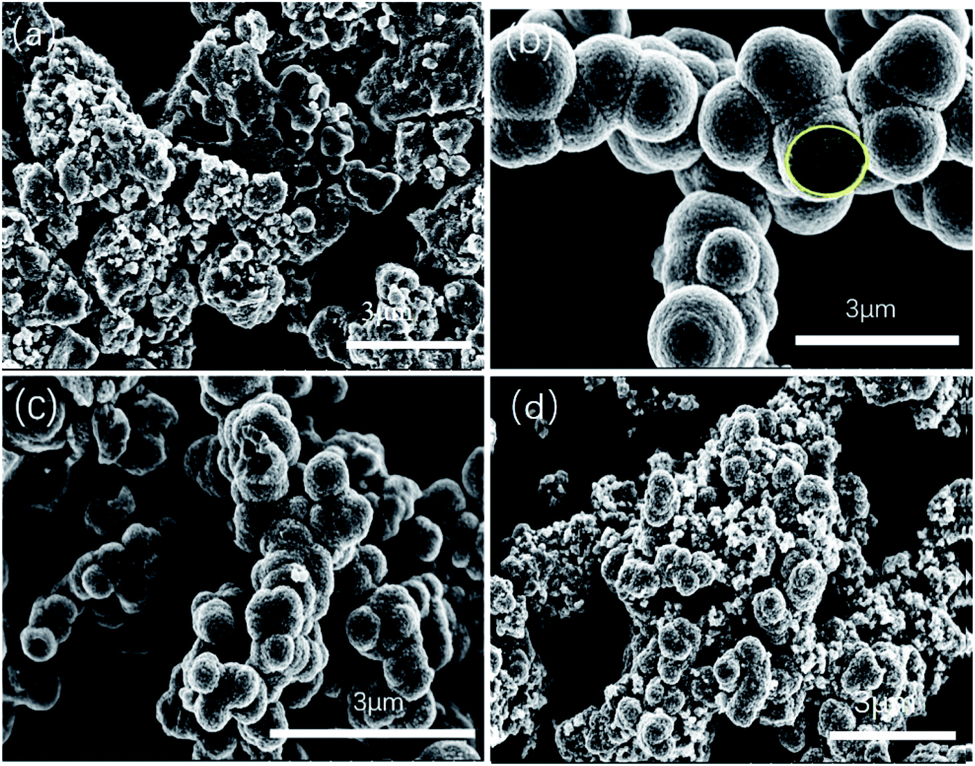 | ||
| Fig. 1 SEM images of the prepared catalysts of SnO2-1:3 (a), SnO2-1:4 (b) hollow sphere, SnO2-1:5 (c) hollow sphere, SnO2-1:6 (d). | ||
As shown in Fig. S1 in ESI,† Cu3P is very small in size, similar in shape to cotton mass with a diameter of about 250 nm. Fig. 2a demonstrated the morphology of Cu3P/SnO2 composites, SnO2 was a sphere with much larger size than that of Cu3P, with a diameter of about 1 μm. Cu3P nanoparticles were clustered on the surface of SnO2 microspheres, with a solid–solid interface formed between the two chemicals. These results demonstrated that Cu3P had been successfully installed on the surface of SnO2.
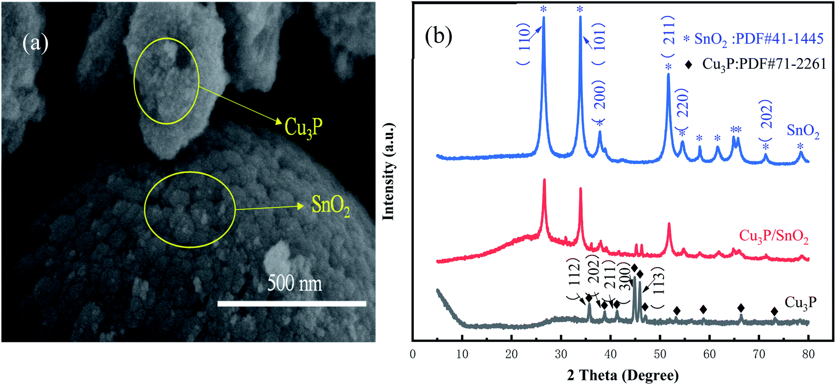 | ||
| Fig. 2 SEM images of Cu3P/SnO2 heterostructure (a) and XRD patterns of the prepared catalysts (b). | ||
XRD patterns in Fig. 2b showed crystalline structures of the synthesized parent materials of Cu3P and SnO2, and the Cu3P/SnO2-3 heterostructure. From XRD pattern of SnO2, the weaker diffraction peaks located at 37.949°, 54.757° and 71.276° which belonged to the (200), (220) and (202) lattice planes of SnO2, while the stronger diffraction peaks located at 26.611°,33.893° and 51.780°, which is attributed to the (110), (101) and (211) lattice planes of SnO2 respectively. XRD pattern of SnO2 in Fig. 2 were keeping up with the standard card (JPDF no. 41-1445).
XRD pattern of Cu3P in Fig. 2 was consistent with the standard card (JPDF no. 71-2261), and the diffraction peaks were at 36.005°, 39.078°, 41.577°, 45.091° and 46.158°, which was corresponded to (112), (202), (211), (300) and (113) lattice planes of Cu3P, respectively. Besides, the purity of Cu3P was very high since there is no extra impurity peak. It is worth noting that both diffraction peak of Cu3P and diffraction peak of SnO2 were plotted in the XRD diffraction pattern (Fig. 2) of the Cu3P/SnO2 heterostructure, indicating the successful combination of Cu3P and SnO2.
Compared with the XRD peaks on the (110), (101) and (211) lattice planes (Fig. 2) of SnO2, the peak width of the Cu3P/SnO2 heterostructure became smaller, reflecting bigger average crystallite size. From Table 1, the average crystallite size of the (110), (101) and (211) lattice planes of SnO2 was 97, 130 and 121 nm. The average crystallite size of Cu3P and SnO2 in the composite increased to some extent. The average crystallite size of the (110), (101) and (211) lattice planes of Cu3P/SnO2 heterostructure was to 143, 168 and 138 nm.
| Sample | Average crystallite size of (110) lattice plane (nm) | Average crystallite size of (101) lattice plane (nm) | Average crystallite size of (211) lattice plane (nm) |
|---|---|---|---|
| SnO2 | 97 | 130 | 121 |
| Cu3P/SnO2 | 143 | 138 | 138 |
The pore size and BET specific surface area were determined by N2 adsorption of the synthesized samples (Fig. 3). Fig. 3a showed the N2 adsorption and desorption isotherms of SnO2 and Cu3P/SnO2-1, 2, 3, and 4. According to the classification standard, the isotherm of the composite Cu3P/SnO2 at a relative pressure (p/p0) of 0.5–1.0 belonged to the IV type isotherm, and a typical H3 hysteresis loop. This verified that composite Cu3P/SnO2 heterostructure was a mesoporous material. Compared with pure SnO2, the BET specific surface area of the heterostructure Cu3P/SnO2-3 increased significantly. According to the BET theoretical calculation model, Table 2 was categorized with the specific surface area of pure SnO2 was 3.7892 m2 g−1, while the specific surface area of Cu3P/SnO2-3 was 53.1470 m2 g−1, which was about 14 times that of SnO2. Fig. 3b showed the pore size distribution curves of Cu3P/SnO2 samples. The pore size of Cu3P/SnO2 heterostructure was distributed around 5–20 nm. Based on BJH theoretical calculation model, the pore volume of SnO2 was 0.003904 cm3 g−1, and the pore volume of Cu3P/SnO2-3 heterostructure was 0.046550 cm3 g−1, with a tremendous increase of 12 times (Table 2). From Table 2, the specific surface area of Cu3P/SnO2-3 was the largest (53.1470 m2 g−1) while the average pore size was the smallest (3.8213 nm). The increase in the surface area were attributed to the surface modification of Cu3P nanoclusters on SnO2. The larger the specific surface area of the sample, the easier of the sample to expose active sites on the surface. As a photocatalyst, it increased the photocatalytic activity of the pollutant tetracycline (TC-HCl).
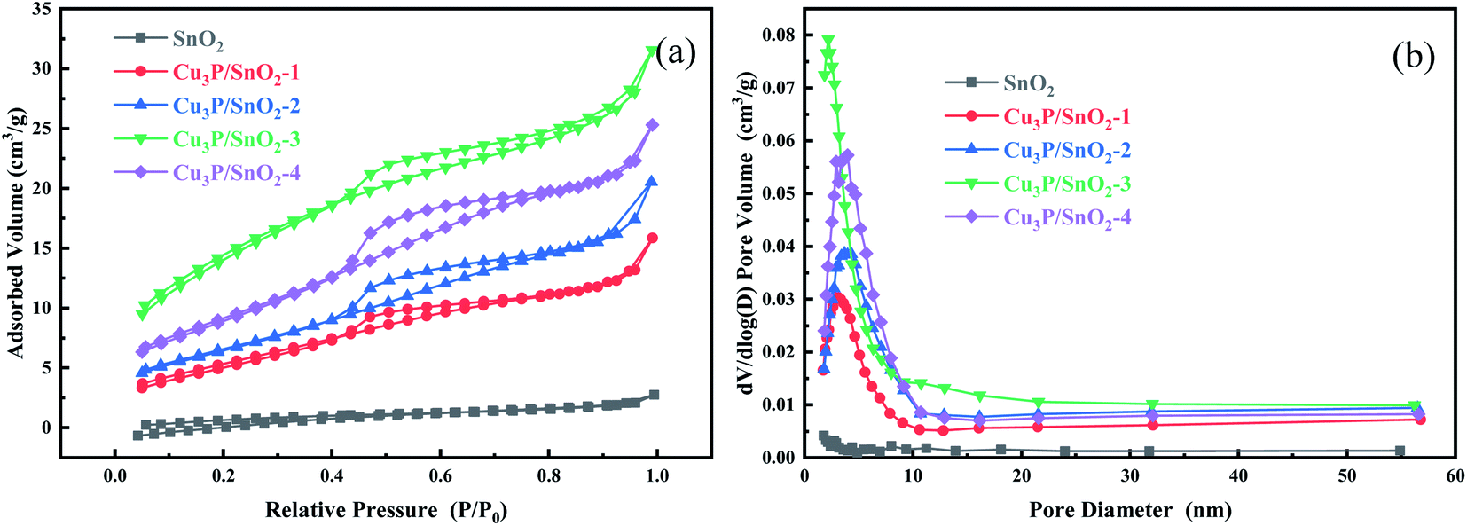 | ||
| Fig. 3 Nitrogen adsorption and desorption isotherms (a) and pore diameter distribution curves (b) of SnO2 and Cu3P/SnO2-1, 2, 3 and 4 composites. | ||
| Sample | Specific surface area (m2 g−1) | Pore volume (cm3 g−1) | Average pore size (nm) |
|---|---|---|---|
| SnO2 | 3.7892 | 0.003904 | 5.4221 |
| Cu3P/SnO2-1 | 20.2940 | 0.023992 | 4.7529 |
| Cu3P/SnO2-2 | 24.3244 | 0.032098 | 4.5883 |
| Cu3P/SnO2-3 | 53.1470 | 0.046650 | 3.8213 |
| Cu3P/SnO2-4 | 33.9863 | 0.039631 | 4.2267 |
In order to study the modification effect of mesoporous Cu3P nanoclusters on SnO2 microspheres to improve its photocatalytic performance, UV-vis DRS was applied to analyze absorption properties of SnO2, Cu3P and Cu3P/SnO2-1–4 heterostructure. Fig. 4a showed the UV-vis absorption spectrum of SnO2, Cu3P and heterostructure Cu3P/SnO2-1, 2, 3, and 4 samples. Cu3P has strong absorption strength in the whole wavelength range, especially in the visible light range. The SnO2 has a strong absorption intensity in range of 200–360 nm (UV), while there was negligible absorption intensity above 400 nm (visible). This indicated that SnO2 can only be excited by ultraviolet photons to undergo electronic transitions, without any optical response in the visible wavelength range. Compared with bare SnO2, the absorption intensity of Cu3P/SnO2 heterostructure was quite different, with a higher absorption intensity in the visible range of 400–800 nm, which was related to the modification effect of mesoporous Cu3P nanoclusters on the surface of SnO2 nanosheets. This indicated a strong interaction between Cu3P and SnO2, which was beneficial to improving the migration efficiency of electron–hole pairs and inhibited their rapid recombination. Furthermore, the band gap values were estimated by Tauc plots and plotted in Fig. 4b. From the Fig. 4b the Eg for Cu3P and SnO2 samples are about 1.31 eV and 3.54 eV, respectively.
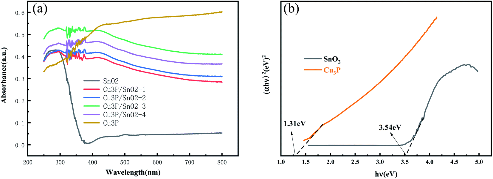 | ||
| Fig. 4 Ultraviolet-visible absorption spectra of SnO2, Cu3P and heterostructure Cu3P/SnO2-1, 2, 3 and 4 samples (a); the gap width of SnO2 and Cu3P samples (b). | ||
Fig. 5 showed the EIS measurements of pure SnO2 and Cu3P/SnO2 samples. The arc size of the Nyquist plot of SnO2 were large due to its large energy gap. In the EIS Nyquist diagram, the smaller the arc size, the smaller the charge transfer resistance and the higher the efficiency of electron–hole separation. Based on previous publications of SnO2 materials,44 different studies reported different results, from 20 to 1250 ohms.45,46 From Fig. 5 the arc diameter of SnO2 was about 120, reflecting the charge transfer resistance Rct of 120 ohms. The Rct of Cu3P/SnO2-3 sample was the smallest (40 ohms), followed by the order of Cu3P/SnO2-1 (80 ohm) > Cu3P/SnO2-2 (60 ohm) and Cu3P/SnO2-4 (50 ohm), respectively. The results indicated that the optimal Cu3P loading is 30% wt. The tight solid–solid interface generated between the two semiconductors of Cu3P and SnO2 turned into a channel for charge transfer, which reduced the charge transfer resistance in interface and improved the migration rate of electric load current carrier.
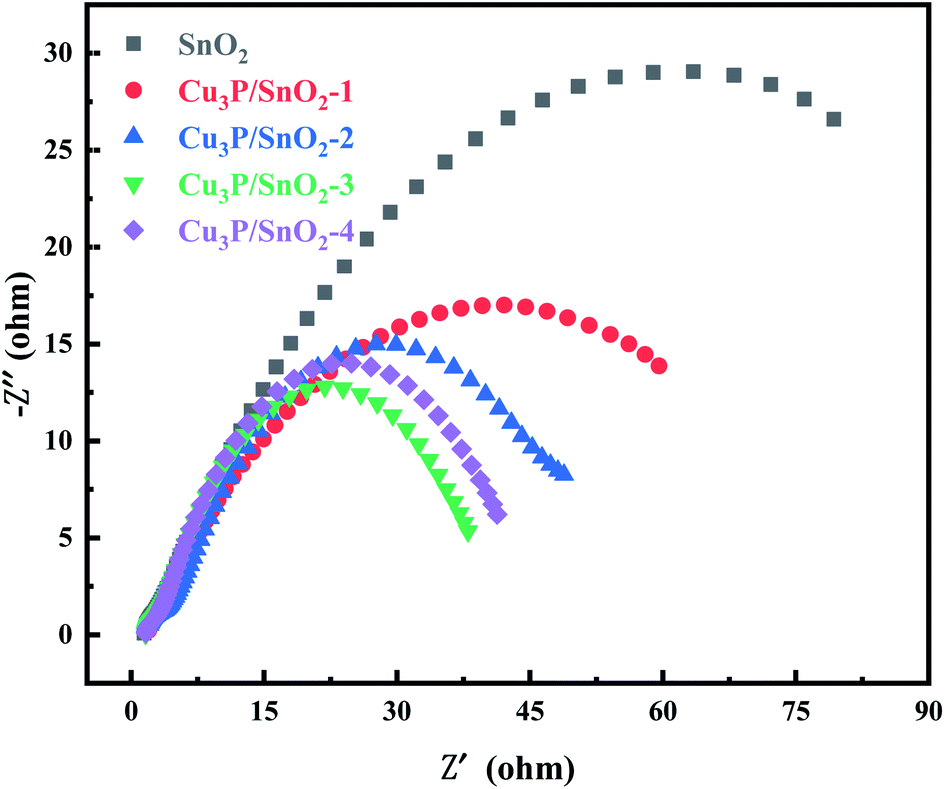 | ||
| Fig. 5 The Nyquist plots of SnO2 and heterostructure Cu3P/SnO2-1, 2, 3 and 4 samples. | ||
3.2. Adsorption and photocatalytic activity evaluation
From the photocatalytic experiment, the photocatalytic activity was explored of different samples under visible light radiation. Fig. 6a showed the dynamic curves of SnO2, Cu3P and composite material heterostructure Cu3P/SnO2-1, 2, 3 and 4 in the photocatalytic degradation of tetracycline. The samples underwent dark reaction adsorption for 30 minutes, and then was irradiated under visible light for 140 minutes. The results showed that after adsorption equilibrium was achieved in the dark, the maximum adsorption capacity was 10% of the heterostructure Cu3P/SnO2-3, and the adsorption capacity of SnO2 sample was 5%, which indicated that the increase of physical adsorption capacity. Such difference was due to the morphological structure of Cu3P/SnO2 composite system increased their specific surface area.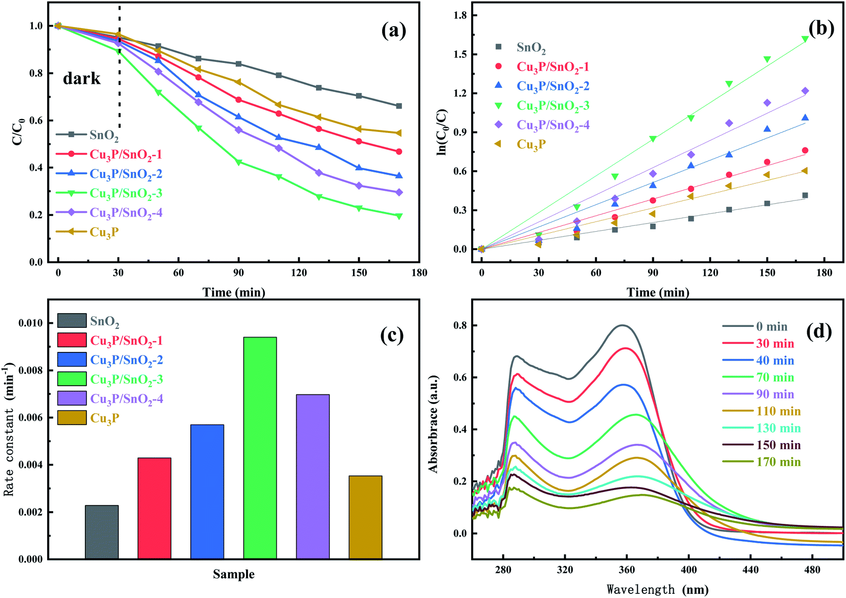 | ||
| Fig. 6 Photocatalytic degradation dynamic curves of SnO2, Cu3P and composite Cu3P/SnO2-1–4 under visible light radiation (a); first-order dynamics fitting curve(b); degradation rate constants of different samples (c); absorption spectra of tetracycline by Cu3P/SnO2-3 at different time points (d). | ||
In the 140 minutes visible light irradiation stage, the degradation effect on tetracycline was obvious. The degradation effects were different of heterostructure materials Cu3P/SnO2-1, 2, 3 and 4 with different composite ratios. The degradation efficiency SnO2 samples was only 35%, since SnO2 cannot fully absorb visible light, and ultraviolet light accounts for a small proportion of visible light. When Cu3P was introduced into the SnO2 material and Cu3P/SnO2 was generated, the photocatalytic degradation effect was significantly enhanced. The photocatalytic degradation effect of Cu3P/SnO2-3 became the best among rest samples and the degradation efficiency reaches 80%. From Fig. 6a, the order of degradation efficiency was: Cu3P/SnO2-3 (80%) > Cu3P/SnO2-4 (70%) > Cu3P/SnO2-2 (64%) > Cu3P/SnO2-1 (53%) > Cu3P(45%) > SnO2 (34%), the higher the better.
Fig. 6b showed the kinetic curves of Fig. 6a, which fitted to the first-order kinetic model ln(C0/C) = kt. The photo degradation process was first order reaction. Fig. 6c was a histogram of the rate constant K of degradation of tetracycline by SnO2, Cu3P and composite heterostructure Cu3P/SnO2-1, 2, 3 and 4. The rate constant k of pure SnO2 and Cu3P were 0.00228 and 0.00353 min−1, while the rate constant k of the sample Cu3P/SnO2-3 was the maximum (k = 0.00940 min−1), which was 4.1 times and 2.7 times than that of SnO2 (k = 0.00228 min−1) and Cu3P (k = 0.00353 min−1), indicating the Cu3P/SnO2 effectively enhanced the photocatalytic degradation efficiency. The rate constant k of the other samples Cu3P/SnO2-1, 2 and 4 were 0.00429, 0.00570 and 0.00697 min−1, respectively. These results verified that the optimal composite percent was 30% wt of Cu3P/SnO2 composite, with the best photocatalytic performance for tetracycline. In addition, Fig. 6d showed the absorption spectra of Cu3P/SnO2-3 for tetracycline at different times. With the gradual extension time of visible light radiation, the characteristic absorption wavelength of 360 nm of tetracycline absorption showed a significant downward trend. This indirectly confirmed that with increased period of visible light radiation, tetracycline gradually was decomposed and opens the ring to breakdown into small molecules or ions.
Table 3 categorized several photocatalysts that had been reported in literature. The results showed that Cu3P/SnO2-3 contained 80% degradation rates, which was comparable with different reported catalysts, such as FeOOH/FeS2 of 90%,47 Ag/Bi3TaO7 of 85% (ref. 48) and Bi12O15Cl6/Bi2WO6 of 81%.49 This work is better than BiFeO3/TiO2 of 72% (ref. 50) and In2S3/InVO4 of 71%.51 Besides, the dosage (Wcat/TC) of Cu3P/SnO2-3 was 25 mg mg−1, which was the minimum around the rest 5 types of catalysts around 50–100 mg mg−1. The amount of catalysts Cu3P/SnO2-3 used in photocatalytic experiment was much less with less pollution and lower cost. This indicates that the catalyst is more favorable to treat the wastewater containing relatively high tetracycline.
| Photocatalysts | Catalyst dosage (mg L−1) | TC concentration (mg L−1) | Wcat/TC (mg mg−1) | Dark (min) | Illumination (min) | Removal rate | Reference |
|---|---|---|---|---|---|---|---|
| FeOOH/FeS2 | 500 | 10 | 50 | 30 | 150 | 90% | Guo et al.47 |
| Ag/Bi3TaO7 | 1000 | 10 | 100 | 60 | 120 | 85% | Luo et al.48 |
| Bi12O15Cl6/Bi2WO6 | 500 | 10 | 50 | 30 | 60 | 81% | Wu et al.49 |
| BiFeO3/TiO2 | 1000 | 10 | 100 | 60 | 180 | 72% | Liao et al.50 |
| In2S3/InVO4 | 500 | 10 | 50 | 60 | 120 | 71% | Yuan et al.51 |
| Cu3P/SnO2 | 1250 | 50 | 25 | 30 | 180 | 80% | This study |
3.3. Stability and degradation mechanism studies 6tb
To evaluate the stability and reusability of the Cu3P/SnO2 heterostructure as a photocatalyst, we conducted five cycles of photodegradation experiments on the Cu3P/SnO2-3 catalyst. After completing a cycle of photodegradation experiment, the catalyst was collected by simple centrifugation, and treated with rinse, drying and other operations. The collected catalyst was prepared for the next cycle experiment. Fig. 7a and b showed the degradation curves and removal efficiency of tetracycline after five cycles. After multiple photodegradation cycles, the degradation efficiency of tetracycline changed a little, from 80% to 75%. After 5 consecutive cycles, it only dropped by 5%. These results proved stability of Cu3P/SnO2-3 as a photocatalyst, and it can be recycled with treatment, which effectively reduced the cost of catalyst production.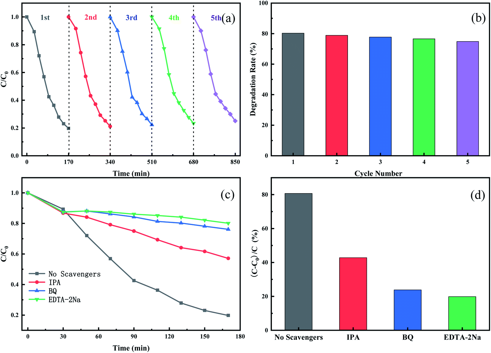 | ||
| Fig. 7 The cyclic degradation curve of tetracycline over heterogeneous Cu3P/SnO2-3 composite catalyst (a); column comparison of degradation rates (b); degradation dynamic curve after the addition of capturing agent (c); histogram of degradation efficiency of different capture agents (d). | ||
The reaction mechanism of tetracycline breakdown was studied by adding active oxidant species capture agent in the photocatalytic reaction stage. Isopropyl alcohol (IPA), benzoquinone (BQ) and ethylene diamine tetra acetic acid disodium salt (EDTA-2Na) were used to capture hydroxyl radical (˙OH), photogenerated holes (h+) and superoxide radicals (˙O2−) of active oxidizing species, respectively. From the kinetic degradation curve (Fig. 7c) and the histogram (Fig. 7d) of degradation efficiency, the degradation of tetracycline by Cu3P/SnO2-3 catalysts was greatly different with different capture reagents. Results showed that the addition of active species capture agent did take into effect. After adding EDTA-2Na and BQ as capturing reagents for h+ and ˙O2− to the photocatalytic reaction pathway, the degradation efficiency of TC-HCl is dropped down to 19% and 24%, much lower than the blank test of non-capturing reagents (80%). This strong inhibitory effect indicated that h+ and ˙O2− played a key role in the degradation of tetracycline, and the effect of h+ was slightly higher than that of ˙O2−. However, if IPA was used as a capture agent for ˙OH, the degradation efficiency of tetracycline drops from 80% to 57%, indicating that ˙OH plays a minor role in the degradation of TC-HCl. In summary, in the process of tetracycline degradation by Cu3P/SnO2 composite, the role of h+, ˙O2− and ˙OH follows h+ > ˙O2− > ˙OH of the degradation reaction.
The ESR measurements were further used to identify ˙O2− in Cu3P/SnO2-3 composite catalysts. As shown in Fig. S2 in ESI,† no signal was detected under dark conditions. Under visible light irradiation, ˙O2− appeared obviously, which proved that the production of the active substance was consistent with the free radical trapping experiment. Therefore, Cu3P/SnO2 photocatalyst showed good performance with the help of reactive oxygen species.
Fig. 8 showed the possible mechanism of the degradation of TC by heterostructure Cu3P/SnO2 catalyst under visible light. In the previous calculation, the band gap values of Cu3P and SnO2 were 1.31 eV and 3.54 eV, respectively. Under the visible light radiation, SnO2 and Cu3P are respectively excited, and the electrons in the valence band (VB) migrate to the conduction band (CB), leaving the hole h+ in the VB. Part of the electrons in the CB of Cu3P were transferred to the CB of SnO2 through the heterostructure interface. H2O molecules trap holes h+ in the VB and convert them into ˙OH, and part of the oxygen O2 molecules adsorbed on the catalyst surface trap electrons e− in the CB and converted them into superoxide radical ˙O2−. Finally, the holes h+, ˙O2− and ˙OH directly oxidize the tetracycline TC molecules. This was the general degradation principles of tetracycline TC by the studied Cu3P/SnO2 heterostructure. The specific and detailed degradation mechanism of tetracycline molecules await future research.
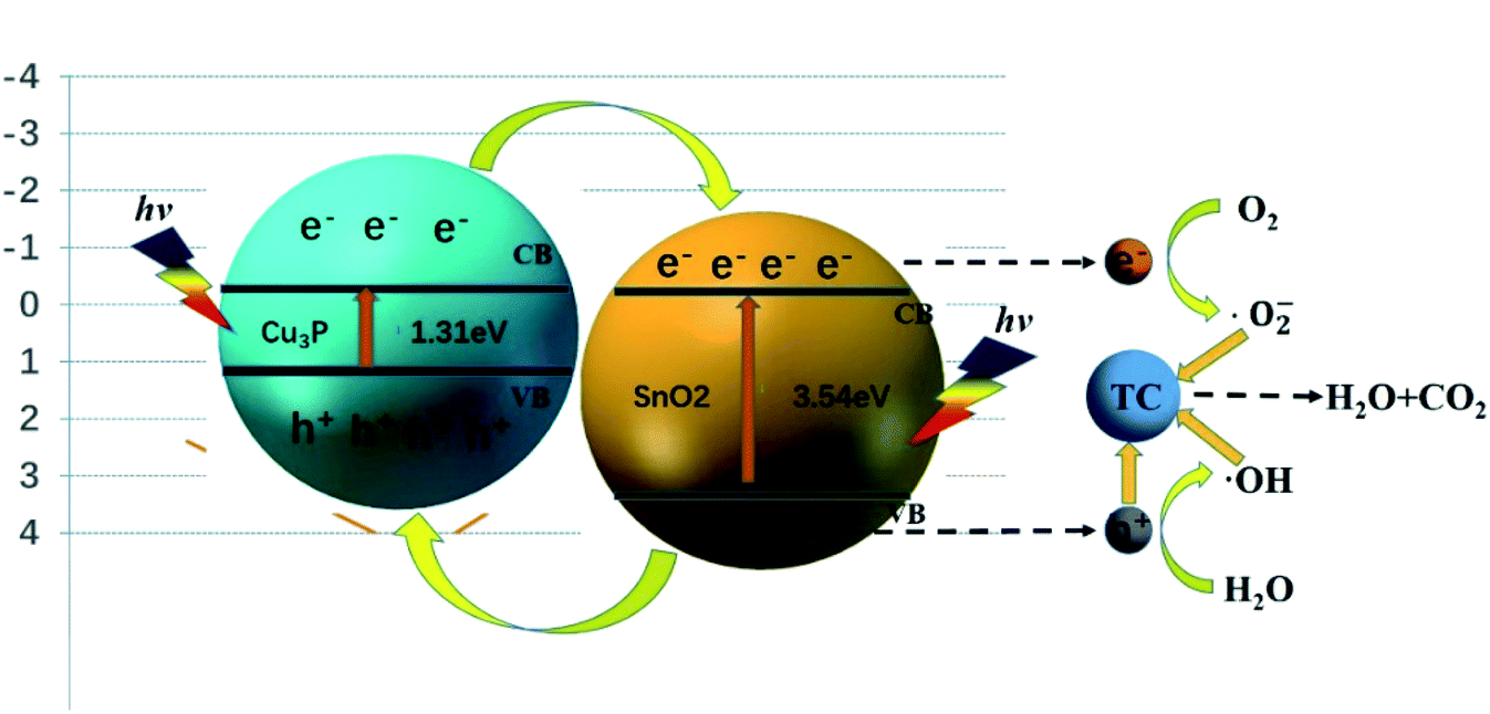 | ||
| Fig. 8 Mechanism diagram of photocatalytic degradation of TC by heterogeneous Cu3P/SnO2. | ||
4. Conclusion
Cu3P/SnO2, the p–n type heterostructure, was proved to be an efficient photocatalyst for the degradation of antibiotic drug pollutants like TC-HCl. Among different Cu3P loaded samples, Cu3P/SnO2-3 (30% load) after 30 minutes of dark reaction adsorption and 140 minutes of photodegradation, the removal efficiency reached 80%, which is 2.3 times of the removal efficiency of SnO2. The improved photocatalytic activity was benefited from the heterogeneous interface between SnO2 and Cu3P, which effectively enhances the efficient charge transfer and retarders the recombination of electron hole pairs. Furthermore, the cyclic photodegradation experiments verified that the heterojunction Cu3P/SnO2-3 was stable and the efficiency dropped 5% after 5 runs. From mechanistic study, the active oxidant species as h+, ˙O2−, and ˙OH were all involved in photocatalytic system. It seems that h+ and ˙O2− played the major role in the photocatalytic degradation of tetracycline by Cu3P/SnO2 composites. Further work may involve the improvement of catalyst with better degradation activity.Conflicts of interest
There are no conflicts to declare.References
- I. Grgic, A. M. Cizmek, S. Babic, D. Ljubas and M. Rozman, J. Environ. Manage., 2021, 289, 112389 CrossRef CAS PubMed.
- I. T. Carvalho and L. Santos, Environ. Int., 2016, 94, 736–757 CrossRef PubMed.
- S. R. Li, W. L. Huang, P. Z. Yang, Z. D. Li, B. Q. Xia, M. J. Li, C. Xue and D. F. Liu, Sci. Total Environ., 2021, 754 Search PubMed.
- Z. Shi, Y. Zhang, X. F. Shen, G. Duoerkun, B. Zhu, L. S. Zhang, M. Q. Li and Z. G. Chen, Chem. Eng. J., 2020, 386 Search PubMed.
- Q. Q. Feng, J. B. Zhou and Y. Zhang, J. Mater. Sci., 2019, 30, 19108–19118 CAS.
- C. Cui, R. H. Guo, H. Y. Xiao, E. Ren, Q. S. Song, C. Xiang, X. X. Lai, J. W. Lan and S. X. Jiang, Appl. Surf. Sci., 2020, 505 Search PubMed.
- L. L. Yu, W. Cao, S. C. Wu, C. Yang and J. H. Cheng, Ecotoxicol. Environ. Saf., 2018, 164, 289–296 CrossRef CAS PubMed.
- S. S. Xin, G. C. Liu, X. H. Ma, J. X. Gong, B. R. Ma, Q. H. Yan, Q. H. Chen, D. Ma, G. S. Zhang, M. C. Gao and Y. J. Xin, Appl. Catal., B, 2021, 280 Search PubMed.
- L. H. Huang, G. F. Liu, G. H. Dong, X. Y. Wu, C. Wang and Y. Y. Liu, Chem. Eng. J., 2017, 316, 525–533 CrossRef CAS.
- A. Dehghan, M. H. Dehghani, R. Nabizadeh, N. Ramezanian, M. Alimohammadi and A. A. Najafpoor, Chem. Eng. Res. Des., 2018, 129, 217–230 CrossRef CAS.
- S. C. Chang, Q. Zhang, Y. K. Lu, S. Z. Wu and W. Wang, Sep. Purif. Technol., 2020, 238 Search PubMed.
- H. Shi, X. Yang, H. Feng, J. Fu, T. Zou, J. Yao, Z. Wang, L. Jiang and P. Tontiwachwuthikul, Ind. Eng. Chem. Res., 2021, 60, 7352–7366 CrossRef CAS.
- C. Y. Jin, M. Wang, Z. L. Li, J. Kang, Y. Zhao, J. Han and Z. M. Wu, Chem. Eng. J., 2020, 398 Search PubMed.
- M. Shekofteh-Gohari, A. Habibi-Yangjeh, M. Abitorabi and A. Rouhi, Crit. Rev. Environ. Sci. Technol., 2018, 48, 806–857 CrossRef CAS.
- A. Akhundi, A. Habibi-Yangjeh, M. Abitorabi and S. R. Pouran, Catal. Rev., 2019, 61, 595–628 CrossRef CAS.
- W. S. Koe, J. W. Lee, W. C. Chong, Y. L. Pang and L. C. Sim, Environ. Sci. Pollut. Res., 2020, 27, 2522–2565 CrossRef CAS PubMed.
- H. Shi, M. Cui, J. Fu, W. Dai, M. Huang, J. Han, L. Quan, P. Tontiwachwuthikul and Z. Liang, Int. J. Greenhouse Gas Control, 2021, 107 Search PubMed.
- Q. Shen, L. Wei, R. Bibi, K. Wang, D. Hao, J. Zhou and N. Li, J. Hazard. Mater., 2021, 413, 125376 CrossRef CAS PubMed.
- H. Song, L. Liu, H. Wang, B. Feng, M. Xiao, Y. Tang, X. Qu, H. Gai and T. Huang, Mater. Sci. Semicond. Process., 2021, 128 Search PubMed.
- W. Mao, L. X. Zhang, T. Y. Wang, Y. C. Bai and Y. T. Guan, Front. Environ. Sci. Eng., 2021, 15 Search PubMed.
- H. Cheema and J. H. Delcamp, Chem.–Eur. J., 2019, 25, 14205–14213 CrossRef CAS PubMed.
- B. L. Zhu, F. Liu, K. Li, K. Lv, J. Wu, Z. H. Gan, J. Liu, D. W. Zeng and C. S. Xie, Ceram. Int., 2017, 43, 10288–10298 CrossRef CAS.
- B. Salah and A. I. Ayesh, Mater. Chem. Phys., 2021, 266 Search PubMed.
- F. Puga, J. A. Navío and M. C. Hidalgo, Sep. Purif. Technol., 2021, 257 Search PubMed.
- H. Z. Wu, C. W. Yuan, R. M. Chen, J. D. Wang, F. Dong, J. Y. Li and Y. J. Sun, ACS Appl. Mater. Interfaces, 2020, 12, 43741–43749 CrossRef CAS PubMed.
- C. Karthikeyan, P. Arunachalam, K. Ramachandran, A. M. Al-Mayouf and S. Karuppuchamy, J. Alloys Compd., 2020, 828 Search PubMed.
- A. M. Al-Hamdi, U. Rinner and M. Sillanpaa, Process Saf. Environ., 2017, 107, 190–205 CrossRef CAS.
- D. Toloman, A. Popa, M. Stefan, T. D. Silipas, R. C. Suciu, L. Barbu-Tudoran and O. Pana, Opt. Mater., 2020, 110 Search PubMed.
- B. Babu, R. Koutavarapu, V. V. N. Harish, J. Shim and K. Yoo, Ceram. Int., 2019, 45, 5743–5750 CrossRef CAS.
- B. Babu, M. Y. Cho, C. Byon and J. Shim, J. Alloys Compd., 2018, 731, 162–171 CrossRef CAS.
- K. Mallikarjuna, G. A. K. M. R. Bari, S. V. P. Vattikuti and H. Kim, Int. J. Hydrogen Energy, 2020, 45, 32789–32796 CrossRef CAS.
- B. Y. Liang, L. J. Zhang, T. C. Zhang, J. Z. Zhang and W. X. Zhang, J. Aust. Ceram. Soc., 2020, 56, 1283–1289 CrossRef.
- H. Lahmar, M. Benamira, S. Douafer, F. Z. Akika, M. Hamdi, I. Avramova and M. Trari, Optik, 2020, 219 Search PubMed.
- R. T. Huang, S. S. Huang, D. Y. Chen, Q. Zhang, T. T. Le, Q. Wang, Z. J. Hu and Z. W. Chen, J. Colloid Interface Sci., 2019, 542, 460–468 CrossRef CAS PubMed.
- Y. Zhang, H. Yang and W. Zou, Micro Nano Lett., 2020, 15, 1033–1037 CrossRef CAS.
- S. F. Chen, F. N. Liu, M. Z. Xu, J. F. Yan, F. C. Zhang, W. Zhao, Z. Y. Zhang, Z. H. Deng, J. N. Yun, R. Y. Chen and C. L. Liu, J. Colloid Interface Sci., 2019, 553, 613–621 CrossRef CAS PubMed.
- H. Bouchaaba, B. Bellal and M. Trari, Theor. Exp. Chem., 2018, 53, 417–422 CrossRef CAS.
- Q. X. Gai, S. T. Ren, X. C. Zheng, W. J. Liu, Q. L. Dong and R. X. Gao, New J. Chem., 2020, 44, 4332–4339 RSC.
- S. Cao, Y. Chen, C. J. Wang, X. J. Lv and W. F. Fu, Chem. Commun., 2015, 51, 8708–8711 RSC.
- W. J. Sun, J. Jia, C. Y. Jin, X. L. Zhang, E. Z. Liu and J. Fan, J. Phys. D: Appl. Phys., 2019, 52(46), 465106 CrossRef CAS.
- X. Z. Yue, S. S. Yi, R. W. Wang, Z. T. Zhang and S. L. Qiu, Nanoscale, 2016, 8, 17516–17523 RSC.
- F. K. Meng, J. T. Li, S. K. Cushing, M. J. Zhi and N. Q. Wu, J. Am. Chem. Soc., 2013, 135, 10286–10289 CrossRef CAS PubMed.
- A. Ioannidi, A. Petala and Z. Frontistis, J. Environ. Chem. Eng., 2020, 8(5), 104340 CrossRef CAS.
- H. C. Shi, Q. M. Wu, L. H. Jiang, L. Wang, M. Huang, B. Han, Z. H. Yu and Y. H. Zuo, Int. J. Electrochem. Sci., 2020, 15, 1539–1547 CrossRef CAS.
- S. Wang, G. S. Li, Z. H. Leng, Y. Wang, S. F. Fang, J. H. Wang, Y. H. Wei and L. P. Wang, Appl. Surf. Sci., 2019, 471, 813–821 CrossRef CAS.
- L. Liao, W. G. Huang, F. G. Cai and Q. Y. Zhang, J. Mater. Sci., 2021, 32, 9540–9550 CAS.
- Y. Guo, C. X. Li, Z. H. Gong, Y. P. Guo, X. G. Wang, B. Gao, W. J. Qin and G. H. Wang, J. Hazard. Mater., 2020, 397 Search PubMed.
- B. F. Luo, D. B. Xu, D. Li, G. L. Wu, M. M. Wu, W. D. Shi and M. Chen, ACS Appl. Mater. Interfaces, 2015, 7, 17061–17069 CrossRef CAS PubMed.
- Z. Y. Wu, X. Yan, H. Shen, J. L. Li and W. D. Shi, Mater. Sci. Eng., B, 2018, 231, 86–92 CrossRef CAS.
- X. L. Liao, T. T. Li, H. T. Ren, Z. Y. Mao, X. F. Zhang, J. H. Lin and C. W. Lou, Ceram. Int., 2021, 47, 10786–10795 CrossRef CAS.
- X. Z. Yuan, L. B. Jiang, J. Liang, Y. Pan, J. Zhang, H. Wang, L. J. Leng, Z. B. Wu, R. P. Guan and G. M. Zeng, Chem. Eng. J., 2019, 356, 371–381 CrossRef CAS.
Footnote |
| † Electronic supplementary information (ESI) available. See DOI: 10.1039/d1ra05905j |
| This journal is © The Royal Society of Chemistry 2021 |