 Open Access Article
A novel purification method for fluoride or chloride molten salts based on the redox of hydrogen on a nickel electrode†
Yong Zuo *abc,
Yu-Long Songabc,
Rui Tangab and
Yuan Qian*abc
aShanghai Institute of Applied Physics, Chinese Academy of Science, Shanghai 201800, China. E-mail: zuoyong@sinap.ac.cn
bDalian National Laboratory for Clean Energy, Chinese Academy of Sciences, Dalian 116023, China. E-mail: qianyuan@sinap.ac.cn
cUniversity of Chinese Academy of Sciences, Beijing 100049, China
First published on 29th October 2021
Abstract
A novel purification process was proposed for molten salts based on the polarization of a hydrogen electrode on nickel, i.e., H+/H2, Ni electrode. The features of the H+/H2, Ni electrode in typical chloride and fluoride molten salts were investigated. Consistent current electrolysis was performed in a feasible polarization range, and the deoxidation efficiency was higher than that of the traditional chemical or electrochemical purification methods in both chloride and fluoride molten salts. Only H2 was used as a purification source gas, and almost no toxic HF or corrosive HCl emissions were used or occurred in the new process. The application range of the proposed method was also discussed.
Introduction
Molten salts attracted considerable attention in energy science and technology due to its unique thermochemical properties,1 such as low vapour pressure at a wide range of liquid working temperatures, high thermal capacity and conductivity, and excellent chemical stability. For instance, fluoride molten salts are employed as a liquid fuel or coolant for molten salt reactor (MSR)2,3 or molten salt fast reactor (MSFR);4 the former was one of the six Generation IV reactors recommended by the GIF.5 The chloride molten salts are regarded as a competitive energy storage medium for the Concentrating Solar Power (CSP) plant.6 The main challenge of the application of molten salts is the compatibility with the structural materials,7–9 usually superalloys10 or just stainless steel.11,12 The impurities, such as water or oxide ion, played an important role in the corrosion mechanisms of molten salt13 since the intrinsic corrosion of high purity fluoride or chloride molten salts is minor.14 Thus, the purification of molten salts is an important work before it was used.15–17The most important and difficult task is to remove O2− from the molten salt because of the pyrohydrolysis of water,18,19 as shown in eqn (1).
| H2O + X− ↔ HX + O2− (or OH−) (X = F, Cl) | (1) |
The threat of HF or HCl is obvious because it can react with the sensitive element of the alloy, usually Cr. The harmfulness of O2− results in two aspects: the first is that the existence of O2− could decrease the oxidation potential of Cr metal, as can be seen from the E–pO2− diagram for Cr,20 which indicates that the Cr in the alloy will be more easily corroded with the aid of O2−. The second is that the O2− in the molten salt may form metal oxide precipitation, such as UO2 in MSR fuel salts21 or MgO in CSP chloride salts.15 The UO2 precipitation may cause a severe nuclear security risk in MSR,22 while the MgO precipitation may cause a flush corrosion or pipe block risk.15 A strict O2− control level was usually set before the purification of fuel salts for MSR.17
The most effective method reported for the purification of fluoride molten salts is the HF–H2 process.17,23,24 The main procedure of the HF–H2 process is the alternate bubbling with H2 and HF & H2 mixture gases for the molten salt. The purification reactions are given in eqn (2)–(5).
| H2 + SO42− → H2O↑ + S2− | (2) |
| HF + O2− → H2O↑ + F− | (3) |
| HF + S2− → H2S↑ + F− | (4) |
| H2 + Mn+ → M↓ + H+ (M = Ni, Fe, Mo…) | (5) |
Oxides, trace sulphate and some metal ion impurities could be removed by the above purification reactions. For our experience,25 the oxide content in the FLiNaK (LiF–NaF–KF, 46.5–11.5–42.0, mol%) salts could be decreased to about 100 ppm with Industrial Excellence Level anhydrous HF (99.96%)26 and 99.999% H2 as the purification source gas. Both the US16,22 and China21,25 employ this HF–H2 process for the purification of fluoride salts for the building of MSRE22 or TMSR.27 Three drawbacks of the process restrict its wide application:25 (1) the time for the single batch lasts too long at about 1 week for 100 kg per batch; (2) the utilization coefficient of HF is lower than 1%, and over 99% of HF directly goes into the off gas during bubbling; (3) trace water, sulphate, and silicon exist in the industrial 99.96% HF, which will restrict the deoxidation level.
For the purification of chloride molten salts, a similar process like HCl–H2 was not reported.28 The corrosion problem of HCl & H2O at high temperature may be an important concern. Mg metal was suggested for use to purify MgCl2–NaCl–KCl (45.4–33.0–21.6, mol%, MNKC) in several works.12,29,30 However, the O2− cannot be removed by Mg, and the excess MgO particles in the salt are still problematic for the application of MNKC in CSP.12,15
The electrochemical purification method was often considered as an alternative for the chemical method.31–34 Electrolysis with graphite electrodes to remove O2− and some transition metal ions from fluoride molten salts was proved to be feasible.31 Recent work by us indicated that the O2− in molten salts can be removed by an SOM anode loaded with liquid Zn as the deoxidizer.34 However, both of the above electrochemical methods have one mutual problem. The current density is too low, and the methods can hardly be applied in large scale. Thus, a novel electrochemical purification method was proposed in this study, which may overcome the problems in traditional chemical or electrochemical methods.
Results and discussion
Electrolytic cell design for the purification of molten salts
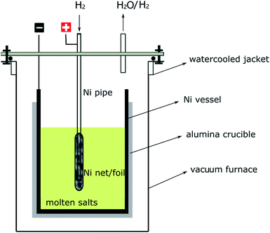
The electrolytic cell shown in Fig. 1 was inspired by the traditional HF–H2 process, in which a nickel pipe was used as a bubbling pipe and nickel vessel as the container for molten salts.25 The nickel bubbling pipe is actually a hydrogen electrode, which can be recorded as H+/H2, Ni. H+ is important for the inhibition of water hydrolysis and the removal of O2− (or S2−) as H2O (or H2S), as can be seen from eqn (1), (3) and (4). If an anodic polarization was performed on the hydrogen electrode, H+ may be produced by the oxidation of H2. So, with the electrolytic cell setup shown in Fig. 1, the molten salts could be purified by electrolysis with only H2 bubbling. The electrode reactions that may happen on the nickel pipe anode or the nickel vessel cathode are given below.Possible anodic reactions:
| H2 – 2e + O2− → H2O(g) | (6) |
| H2 – 2e + 2OH− → 2H2O(g) | (7) |
| H2 – 2e + S2− → H2S(g) | (8) |
| H2 – 2e + 2X− → 2HX(g) (X = F, Cl) | (9) |
Possible cathodic reactions:
| MXn + ne → nX− + M (M = Ni, Fe, Mo…) | (10) |
| SO42− + 8e → S2− + 4O2− | (11) |
| 2OH− + 2e → H2(g) + 2O2− | (12) |
| 2H+ + 2e → H2(g) | (13) |
Except for the above electrochemical reactions, the chemical reactions shown in eqn (2)–(5) may also occur in the bulk solution owing to the existence of H2 and H+ in the salt solution.
The superiority of the new method can be listed as follow:
(1) No need for HF or HCl yet the method can be used for both fluoride and chloride molten salts.
(2) Electrochemical and chemical reactions happened simultaneously; the purification efficiency will be highly improved.
(3) H+ produced at the interface of molten salts, gas and nickel electrode and will be more easily dissolve and diffuse into the molten salt.35 Excessive H+ can be reduced to H2, as shown in eqn (13). These two effects indicated that less HF (or HCl) will go into the off gas, as compared with the traditional HF–H2 process (or the possible HCl–H2 process).
(4) The H+ was transferred from high purity H2, e.g., 99.999%; no impurities (such as water, sulphate, and silicon) can be carried like the industrial 99.96% HF.26 The deoxidation level is expected to be superior to that of the traditional HF–H2 process using industrial HF. After all, the 99.999% H2 is cheap, while the 99.999% HF is very expensive.
More advantages of the new purification method may be examined by experimental research.
Features of hydrogen electrode in MNKC system
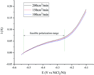
The transfer speed of H2 to H+ is related to the anodic polarization current density and the effective working area of the hydrogen electrode. A nickel net or foil belt could be connected around the export of the nickel pipe to improve the apparent working area (see Fig. 1). The current density of the hydrogen electrode is determined by the polarization over potential and the exchange current density, which is relevant to the H2 velocity and temperature. Fig. 2 and 3 present a group of polarization curves of the H+/H2, Ni electrode under different H2 flow rates in MNKC melts at 600 °C. It can be seen from the i–E curves in Fig. 2 that the current increases with increasing H2 velocity and the increasing over potential.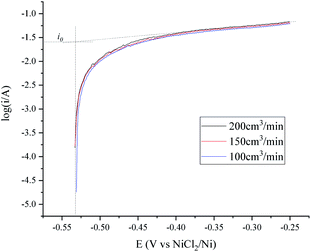 | ||
| Fig. 3 Tafel plots of the H+/H2, Ni electrode under different H2 flow rates in 600 °C MNKC melts. The apparent working area of the H+/H2, Ni electrode is about 12.8 cm2. Scan rate: 0.01 V s−1. | ||
The OCP (Open Circuit Potential) of the H+/H2, Ni electrode was varied slightly with the changing H2 velocity, which may be explained by the minor fluctuations of the H2 partial pressure and the H+ activity on the nickel electrode. A break point at about −0.25 V was found for all of the three i–E curves shown in Fig. 2, which indicated that a new reaction emerged. The potential difference between the break point and the OCP is close to the calculated standard potential difference of the H+/H2 and Ni2+/Ni electrode (see ESI†). Thus, the reaction that emerged at −0.25 V is quite possibly ascribed to the oxidation of nickel. Therefore, to avoid the oxidation of the nickel electrode, a feasible polarization range for the H+/H2, Ni electrode is from the OCP to the breakpoint (Emax), as shown in Fig. 2. The Tafel plots in the feasible polarization range (Fig. 3) could be used to evaluate the exchange current density of the H+/H2, Ni electrode36 under different H2 flow rates. The results are summarized and listed in Table 1. Results indicated that with increasing H2 flow rate, a higher exchange current i0 and maximum polarization current imax in the feasible polarization range could be obtained. It also can be seen from Fig. 2 and 3 that the dependence of the current on the H2 flow rate appears to be not too strong in the experimental conditions. So, only the H2 flow rate of 150 cm3 min−1 was employed in the next experimental study.
| H2 flow rate (cm3 min−1) | |||
|---|---|---|---|
| 100 | 150 | 200 | |
| i0 (mA) | 23.2 | 24.8 | 25.6 |
| OCP (V vs. NiCl2/Ni) | −0.531 | −0.533 | −0.533 |
| Emax (V vs. NiCl2/Ni) | −0.25 | −0.25 | −0.25 |
| imax (mA) | 61.0 | 63.6 | 67.4 |
A temperature dependence research study of the H+/H2, Ni electrode with 150 cm3 min−1 H2 flow rate in MNKC melts was investigated in another group of tests. The polarization curves and Tafel plots are shown in Fig. 4 and 5, respectively. The characteristics of the hydrogen electrode are summarized in Table 2. It can be seen that with increasing temperature, the exchange current i0 and the maximum polarization current imax in the feasible polarization range improved. Meanwhile, the maximum polarization potential Emax seemed to slightly decrease with increasing temperature.
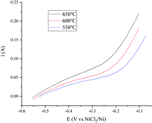 | ||
| Fig. 4 Polarization curves of the H+/H2, Ni electrode at different temperatures in MNKC melts. The apparent working area of the H+/H2, Ni electrode is about 12.8 cm2. Scan rate: 0.01 V s−1. | ||
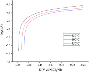 | ||
| Fig. 5 Tafel plots of the H+/H2, Ni electrode at different temperatures in MNKC melts. The apparent working area of the H+/H2, Ni electrode is about 12.8 cm2. Scan rate: 0.01 V s−1. | ||
| Temperature (°C) | |||
|---|---|---|---|
| 550 | 600 | 650 | |
| i0 (mA) | 20.6 | 24.8 | 26.7 |
| OCP (V vs. NiCl2/Ni) | −0.521 | −0.533 | −0.547 |
| Emax (V vs. NiCl2/Ni) | −0.24 | −0.25 | −0.26 |
| imax (mA) | 54.3 | 63.6 | 84.3 |
To avoid the over polarization of the H+/H2, Ni electrode, a consistent current of 20 mA was employed for the purification of 500 g MNKC salts at 600 °C with the H2 flow rate of 150 cm3 min−1. The potential difference between the vessel and the hydrogen electrode (Fig. 1) was recorded (Fig. 6) using the hydrogen electrode itself as a reference electrode in a two-electrode electrochemical measuring system. After 3.5 h electrolysis, the MNKC salts were sampled. The total oxygen content was analysed by a LECO RO600 analyser, and the result was compared with that before electrolysis. The oxygen content before and after electrolysis were 547 and 159 ppm and the analytical RSD were 0.05 and 0.10, respectively. The content of oxygen removed (194.0 mg) was much high than that of the maximum theoretical amount (41.8 mg) that could be removed by electrolysis, as can be evaluated by coulometry from eqn (7). This phenomenon indicated that the chemical purification effect is also working in the electrolysis process.
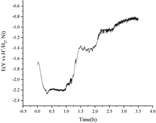 | ||
| Fig. 6 Purification of 500 g MNKC salts by consistent current (20 mA) electrolysis using a H+/H2, Ni electrode with an apparent working area of 12.8 cm2. Temperature: 600 °C. | ||
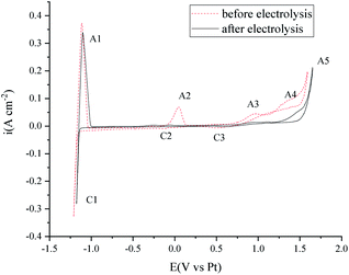
Cyclic voltammetry was also performed before and after the electrolysis to investigate the purity change of the MNKC salts. As can be seen from Fig. 7, the cathodic (C1/A1) and anodic (A5) limit of the curves are the reduction of Mg and the oxidation of Cl−, respectively. The reduction peak of C2 was proved to be the reduction of MgOHCl and A2 is the oxidation of the product of C2.37 The C3/A3 peak may be attributed to the redox of W with the existence of O2−. The peak A4 is attributed to the oxidation of O2−,12 which is the main impurity to be removed for our purpose.
After 3.5 h electrolysis, the C2/A2 peak almost diminished, which may be ascribed to the electrochemical reaction (7) or (12). The height of C3/A3 and A4 decreased a lot, which indicated that the O2− content decreased a lot. The electrochemical investigation is consistent with the oxygen analysis results.
Features of the hydrogen electrode in the FLiNaK system
The features of the H+/H2, Ni electrode in fluoride salts were investigated in the widely researched FLiNaK melts.24,25,38 The polarization curves and Tafel plots of the H+/H2, Ni electrode with 150 cm3 min−1 flow rate are presented in Fig. 8 and 9. The exchange current i0 and maximum polarization current imax in the feasible potential range at different temperatures are listed in Table 3. The characteristic variation trend of the hydrogen electrode is similar to that in the MNKC melts. What is different is that the current is much lower than that in the MNKC melts. The reason why the current of the same H+/H2, Ni electrode in the FLiNaK melts is much lower than that in the MNKC melts is not yet known. More work needs to be done in the future to examine the reason for the difference.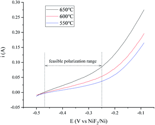 | ||
| Fig. 8 Polarization curves of the H+/H2, Ni electrode at different temperatures in the FLiNaK melts. The apparent working area of the H+/H2, Ni electrode is about 12.8 cm2. Scan rate: 0.01 V s−1. | ||
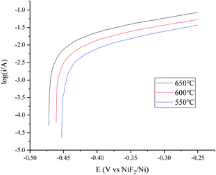 | ||
| Fig. 9 Tafel plots of the H+/H2, Ni electrode at different temperatures in FLiNaK melts. The apparent working area of the H+/H2, Ni electrode is about 12.8 cm2. Scan rate: 0.01 V s−1. | ||
| Temperature (°C) | |||
|---|---|---|---|
| 550 | 600 | 650 | |
| i0 (mA) | 5.81 | 10.2 | 14.6 |
| OCP (V vs. NiF2/Ni) | −0.453 | −0.461 | −0.472 |
| Emax (V vs. NiF2/Ni) | −0.25 | −0.25 | −0.25 |
| imax (mA) | 36.9 | 53.3 | 85.0 |
To improve the transfer rate of H2 to H+ in the purification of the FLiNaK salts, a higher temperature of 650 °C was employed according to the data lists in Table 3. A consistent current of 15 mA was applied for the purification of 500 g FLiNaK salts with the H2 flow rate of 150 cm3 min−1. The potential difference between the nickel vessel and the H+/H2, Ni electrode became stable at about 90 min and the electrolysis stopped at 120 min, as shown in Fig. 10. The total oxygen content in the FLiNaK salts before and after the electrolysis were analysed by LECO RO600 analyser. The results are 665 and 138 ppm with an RSD of 0.05 and 0.10, respectively. The purification efficiency is much higher than that of the traditional HF–H2 process25 or the commonly used electrochemical methods31 (see Table 4).
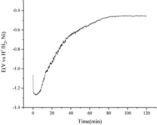 | ||
| Fig. 10 Purification of 500 g FLiNaK salts by consistent current (15 mA) electrolysis using a H+/H2, Ni electrode with an apparent working area of 12.8 cm2. Temperature: 650 °C. | ||
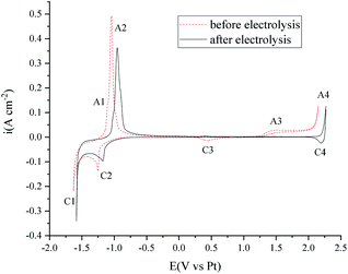
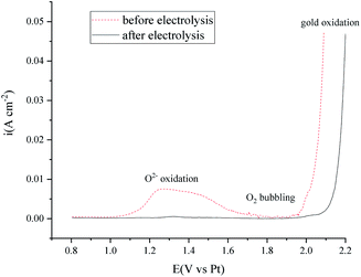
The voltammetry studies of the FLiNaK melts were also performed before and after electrolysis. As shown in Fig. 11, the C1/A1 and C2/A2 peaks on the cyclic voltammetry curves can be attributed to the underpotential deposition of K or Na on the Au electrode.39 Peak A4/C4 is the redox of the Au electrode. The C3 reduction peak may be the transition metal impurities. The A3 peak is attributed to the oxidation of O2− on the Au electrode.40 After 120 min electrolysis (shown in Fig. 10), the peaks C3 and A3 are almost totally diminished.
Further investigation into the oxidation of O2− on the Au electrode by square wave voltammetry method (Fig. 12) indicated that the O2− content in the FLiNaK salts after electrolysis is ultra-low, according to the scale plate from our previous work.40
Why is it a green process?
Up to now, the proposed purification method for fluoride or chloride molten salts have been proved to be feasible by experimental investigation. There are several reasons why we would consider the purification method as a green process.(1) Compared with traditional HF–H2 or the possible HCl–H2 process, no toxic HF or corrosive HCl is needed for the purification of high purity salts.
(2) The produced H+ is more likely to react with O2− or OH−, as shown in eqn (6) and (7), rather than F− or Cl− (as shown in eqn (9)) because of the stronger basicity of the former oxides.41 If the reaction shown in eqn (9) became the major anodic reaction, then it is time to stop the purification process. So, little HF or HCl would go into the off gas, not to mention the possible reduction of excess H+ on the cathode, as shown in eqn (13). While for the traditional HF–H2 process, over 99% of the HF goes into the off gas, as mentioned in the Introduction section.
(3) Electrical power consumption is a great concern for the handling of the molten salts. Although the electrolysis may consume some electrical power, the time for the purification process is greatly shortened as compared to the traditional HF–H2 process. The power for keeping the liquid state of the molten salts decreases to about 10% of the HF–H2 process, which was evaluated from the bubbling time.25 The high efficiency of the new process is due to the coexistence of the chemical and electrochemical purification effects, as mentioned earlier. Otherwise, avoiding the use of the industrial grade HF may also be an important reason for the high efficiency of the new process.
Is it suitable for the purification of all fluorides or chlorides?
The proposed purification process is not suitable for all fluorides or chlorides. Some of the inert transition metal ions, such as Ni2+, Fe2+, and Mo3+, can easily be reduced by H2 in the experimental temperature range (550–650 °C), as shown in eqn (5). Thus, salts like NiCl2 or FeF2 can only “act as impurities” in the proposed process. Cr2+ cannot be reduced to Cr metal, while Cr3+ can be reduced to Cr2+ by H2 in the experimental temperature range, according to thermodynamic calculations (see ESI†). So, if the goal is to obtain high purity salts containing CrF2 or CrCl2, the new method may be attempted. Meanwhile, for CrF3 or CrCl3, it can only act as a source for CrF2 or CrCl2, and not as the constituent of the product.A lenient rule was employed to judge if the salts could be purified by the proposed new process, which is according to the electronegativity value of the metal element. The electronegativity value of Cr, i.e., 1.66, was taken as a criterion.42 Fluoride or chloride salts consisting of a metal element with an electronegativity value of lower than 1.66 may be purified by the proposed method. This criterion is actually also suitable for the traditional HF–H2 or the possible HCl–H2 process. Fig. 13 shows the suggested range of the salt composition in which the new purification process may be applied. Many studies are worthy to be done in the future, as LiF–BeF2, LiF–BeF2–ZrF4–UF4, and LiF–ThF4 are be covered by this new process. These fluoride salts are important coolants or fuel salts for MSR or MSFR and until now, only the HF–H2 purification process could be chosen.16,17,23
 | ||
| Fig. 13 Possible constituents of the salts that can be purified by the proposed new purification process. | ||
Experimental
All of the molten salts including MNKC and FLiNaK were prepared from A.R. grade reagents. The salts were melted in a vertical furnace, which were collected with an Ar atmosphere glove box that has been described in detail in our previous work.21,40 The electrochemical test or electrolysis was also performed in this setup with a CHI1140b potentiostat. O2 and H2O in the glove box under Ar atmosphere were controlled below 2 ppm.The H+/H2, Ni electrode was made from a nickel pipe (φ 6 mm × 3.5 mm) and a nickel foil belt (width: 8 mm; thickness: 0.05 mm), which were bound together by a nickel wire (φ 1 mm) (see ESI†). The apparent working area of the H+/H2, Ni electrode was evaluated by the total surface of the nickel material that was immersed into the molten salts. A nickel vessel was employed as a container for the molten salts, and was taken as a cathode or counter electrode in the electrolysis or electrochemical tests. The purity of all of the nickel materials is over 99.5%.
A NiCl2/Ni reference electrode (20 wt% NiCl2 dissolved in MNKC salts and sealed in a Pyrex glass tube) and a NiF2/Ni reference electrode (20 wt% NiF2 dissolved in FLiNaK salts and sealed in a HBN tube) were employed for the electrochemical investigation of the H+/H2, Ni electrode in MNKC and FLiNaK melts, respectively (see ESI†). While for the voltammetry investigation of the molten salts, a 99.95% Pt wire (φ 1 mm) was used as a pseudo reference electrode in both chloride and fluoride molten salt systems. In two-electrode electrolysis tests, the H+/H2, Ni electrode itself was taken as the reference electrode, as the potential variation of the H+/H2, Ni electrode is minor under a consistent current (see ESI†). A 99.95% W wire (φ 1 mm) was used as the working electrode for the voltammetry tests in chloride molten salts, while a 99.95% Au wire (φ 1 mm) was used for the fluoride molten salts. High purity H2 of 99.999% was supplied for the H+/H2, Ni electrode and a high-precision hydrogen flow meter (KOFLOC 8500) was used to control the flow rate. The total oxygen content in the molten salts were analysed by a LECO RO600 analyzer.
Conclusions
A hydrogen electrode on nickel, i.e., H+/H2, Ni, was employed to convert part of H2 to H+ at the interface of the nickel, H2 gas, and molten salts in the proposed new purification process for fluoride or chloride molten salts. Compared with the traditional HF–H2 process or the commonly used electrolysis method with graphite electrodes, high purification efficiency was proved by experimental methods for the new process in both chloride and fluoride molten salt systems. The coexistence of chemical and electrochemical purification effects may be the reason for the high efficiency. Only H2 was used as a purification source gas, and almost no toxic HF or corrosive HCl emissions were occurred. The proposed new process is highly recommended for the substitution of the HF–H2 process in the purification of fluoride salts for MSR or MSFR. However, the features of the H+/H2, Ni electrode should be carefully examined in different molten salt systems before it is applied.Author contributions
Y. Zuo proposed the ideas of the new process, designed the investigation, and wrote the original draft. Y. L. Song set up the experimental devices. R. Tang provided important materials and reagents. Y. Qian supervised the study and reviewed the draft.Conflicts of interest
There are no conflicts to declare.Acknowledgements
This work was supported by the “Transformational Technologies for Clean Energy and Demonstration”, Strategic Priority Research Program of the Chinese Academy of Sciences, Grant No. XDA21000000.Notes and references
- D. F. Williams, Assessment of candidate molten salt coolant for the NGNP/NHI heat-transfer loop, ORNL/TM−2006/69, 2006 Search PubMed.
- R. R. Romatoski and L. W. Hu, Ann. Nucl. Energy, 2017, 109, 635–647 CrossRef CAS.
- R. W. Moir, Energy Convers. Manage., 2008, 49, 1849–1858 CrossRef CAS.
- B. Merk, D. Litskevich, R. Gregg and A. R. Mount, PLoS One, 2018, 13(3), e0192020 CrossRef CAS PubMed.
- J. Serp, M. Allibert, O. Benes, S. Delpech, O. Feynberg, V. Ghetta, D. Heuer, D. Holcomb, V. Ignatiev, J. L. Kloosterman, L. Luzzi, E. Merle-Lucotte, J. Uhlir, R. Yoshioka and Z. Dai, Prog. Nucl. Energy, 2014, 77, 308–319 CrossRef CAS.
- G. Mohan, M. Venkataraman, J. Gomez-Vidal and J. Coventry, Sol. Energy, 2018, 176, 350–357 CrossRef CAS.
- W. Ding, A. Bonk and T. Bauer, Front. Chem. Sci. Eng., 2018, 12, 564–576 CrossRef CAS.
- S. Guo, J. Zhang, W. Wu and W. Zhou, Prog. Mater. Sci., 2018, 97, 448–487 CrossRef CAS.
- B. A. Pint, J. W. McMurray, A. W. Willoughby, J. M. Kurley, S. R. Pearson, M. J. Lance, D. N. Leonard, H. M. Meyer, J. Jun, S. S. Raiman and R. T. Mayes, Mater. Corros., 2019, 70, 1439–1449 CrossRef CAS.
- N. S. Patel, V. Pavlik and M. Boca, Crit. Rev. Solid State Mater. Sci., 2017, 42, 83–97 CrossRef CAS.
- S. Durra and A. Kundu, Mater. Perform., 2018, 57, 36–39 Search PubMed.
- Y. Zuo, M. Cao, M. Shen and X. Yang, J. Chin. Soc. Corros. Prot., 2021, 41, 80–86 Search PubMed.
- Y. L. Wang, Q. Wang, H. J. Liu and C. L. Zeng, Corros. Sci., 2016, 103, 268–282 CrossRef CAS.
- K. Vignarooban, P. Pugazhendhi, C. Tucker, D. Gervasio and A. M. Kannan, Sol. Energy, 2014, 103, 62–69 CrossRef CAS.
- J. M. Kurley, P. W. Halstenberg, A. McAlister, S. Raiman, S. Dai and R. T. Mayes, RSC Adv., 2019, 9, 25602–25608 RSC.
- J. McFarlane, E. Dominguez-Ontiveros, D. Felde, J. Keiser, J. Massengale, K. Robb, A. Willoughby and G. Yoder, Abstr. Am. Chem. Soc., 2018, 256, 8 Search PubMed.
- J. E. Seifried, R. O. Scarlat, P. F. Peterson and E. Greenspan, Nucl. Eng. Des., 2019, 343, 85–95 CrossRef CAS.
- J. E. Vindstad, H. Mediaas and T. Ostvold, Acta Chem. Scand., 1997, 51, 1192–1200 CrossRef CAS.
- C. F. Baes, J. Nucl. Mater., 1974, 51, 149–162 CrossRef CAS.
- C. L. Zeng, J. Q. Zhang and W. Wu, Corros. Sci. Prot. Technol., 1992, 4, 16–26 Search PubMed.
- Y. Song, M. Shen, S. Zhao, R. Tang, L. Xie and Y. Qian, J. Electrochem. Soc., 2021, 168, 036513 CrossRef CAS.
- M. W. Rosenthal, P. N. Haubenreich and R. B. Briggs, The development status of molten salt breeder reactors, ORNL-4812, 1972 Search PubMed.
- G. Zong and J. Xiao, Chem. Ind. Eng. Prog., 2018, 37, 2455–2472 Search PubMed.
- G. Zong, Z. B. Zhang, J. H. Sun and J. C. Xiao, J. Fluorine Chem., 2017, 197, 134–141 CrossRef CAS.
- Y. Zuo, Y. Wang, R. Tang, S. F. Zhao, X. Z. Su, J. Hou and L. D. Xie, China Pat., CN108376570A, 2016 Search PubMed.
- S. J. Li, T. E. Wang and Y. H. Xu, Industrial Anhydrous Hydrogen Fluoride, GB/T, 7746-2011, 2011 Search PubMed.
- Z. Dai, in Molten Salt Reactors and Thorium Energy, ed. T. J. Dolan, Woodhead Publishing, 2017, pp. 531–540, DOI:10.1016/B978-0-08-101126-3.00017-8.
- K. Zhang, Y. Wang, Y. Xiao, R. Lin, Y. Jia and H. He, J. Nucl. Radiochem., 2018, 40, 382–387 Search PubMed.
- H. Sun, J. Q. Wang, Z. Tang, Y. Liu and C. Wang, Corros. Sci., 2020, 164, 108350 CrossRef CAS.
- B. A. T. Mehrabadi, J. W. Weidner, B. Garcia-Diaz, M. Martinez-Rodriguez, L. Olson and S. Shimpalee, J. Electrochem. Soc., 2017, 164, C171–C179 CrossRef CAS.
- H. Wang, S. Liu, B. Li and Z. Zhao, J. Fluorine Chem., 2015, 175, 28–31 CrossRef CAS.
- W. Ding, F. Yang, A. Bonk and T. Bauer, Sol. Energy Mater. Sol. Cells, 2021, 223, 110979 CrossRef CAS.
- W. Ding, J. Gomez-Vidal, A. Bonk and T. Bauer, Sol. Energy Mater. Sol. Cells, 2019, 199, 8–15 CrossRef CAS.
- Y. Zuo, M. Shen, L. D. Xie, H. W. Xie and Y. C. Zhai, Nucl. Technol., 2020, 43, 110301 Search PubMed.
- K. Wang and P. Chartrand, Phys. Chem. Chem. Phys., 2018, 20, 17324–17341 RSC.
- A. Frignani, C. Monticelli and M. Tassinari, Electrochemical Methods: Fundamentals and Applications, Wiley, New York, 2001 Search PubMed.
- W. Ding, A. Bonk, J. Gussone and T. Bauer, J. Energy Storage, 2018, 15, 408–414 CrossRef.
- F. Y. Ouyang, C. H. Chang, B. C. You, T. K. Yeh and J. J. Kai, J. Nucl. Mater., 2013, 437, 201–207 CrossRef CAS.
- H. Qiao, T. Nohira and Y. Ito, Electrochim. Acta, 2002, 47, 4543–4549 CrossRef CAS.
- M. Shen, H. Peng, M. Ge, Y. Zuo and L. Xie, J. Electroanal. Chem., 2015, 748, 34–39 CrossRef CAS.
- C. Laurence, J. Graton and J. F. Gal, J. Chem. Educ., 2011, 88, 1651–1657 CrossRef CAS.
- J. A. Alonso and L. A. Girifalco, Phys. Rev. B: Condens. Matter Mater. Phys., 1979, 19, 3889–3895 CrossRef CAS.
Footnote |
| † Electronic supplementary information (ESI) available. See DOI: 10.1039/d1ra05794d |
| This journal is © The Royal Society of Chemistry 2021 |

