
 Open Access Article
 This Open Access Article is licensed under a Creative Commons Attribution-Non Commercial 3.0 Unported Licence
Thermophysical properties of lithium thiogallate that are important for optical applications†
Alexey Kurus ab,
Alexander Yelisseyevab,
Sergei Lobanovab,
Pavel Plyusninc,
Maxim Molokeevde,
Leonid Solovyevf,
Dmitry Samoshking,
Sergei Stankusg,
Svetlana Melnikovad and
Lyudmila Isaenkoab
ab,
Alexander Yelisseyevab,
Sergei Lobanovab,
Pavel Plyusninc,
Maxim Molokeevde,
Leonid Solovyevf,
Dmitry Samoshking,
Sergei Stankusg,
Svetlana Melnikovad and
Lyudmila Isaenkoab
aNovosibirsk State University, 2 Pirogov str., Novosibirsk, 630090, Russia. E-mail: kurusaf@igm.nsc.ru
bSobolev Institute of Geology and Mineralogy SB RAS, 3 Kopyug ave., Novosibirsk, 630090, Russia
cNikolaev Institute of Inorganic Chemistry SB RAS, 3 Lavrentyev ave., Novosibirsk, 630090, Russia
dKirensky Institute of Physics SB RAS, Krasnoyarsk, 660036, Russia
eSiberian Federal University, Krasnoyarsk 660041, Russia
fInstitute of Chemistry and Chemical Technology SB RAS, 42 K. Marx str., Krasnoyarsk, 66049, Russia
gKutateladze Institute of Thermophysics SB RAS, 1 Lavrentyev ave., Novosibirsk, 630090, Russia
First published on 8th December 2021
Abstract
Lithium thiogallate LiGaS2 is one of the most common nonlinear crystals for mid-IR due to its extreme beam strength and wide transparency range; however, its thermophysical properties have not yet been practically studied. Large crystals of high optical quality are grown. DTA revealed features at 1224 K below melting point (1304 K) that are associated with the oxygen containing compounds of the LiGaO2−xSx type. The thermal conductivity of LiGaS2 (about 10.05 W (m−1 K−1)) and band gap value (3.93 eV at 300 K) are found to be the highest in the LiBC2 family. Isotropic points in the dispersion characteristics for the refractive index are found and LiGaS2-based narrow-band optical filters, smoothly tunable with temperature changes, are demonstrated. Intense blue photoluminescence of anionic vacancies VS is observed at room temperature after annealing LiGaS2 in vacuum, whereas orange low-temperature emission is related to self-trapped excitons. When LiGaS2 crystals are heated, spontaneous luminescence (pyroluminescence) takes place, or thermoluminescence after preliminary UV excitation; the parameters of traps of charge carriers are estimated. The obtained data confirm the high optical stability of this material and open up prospects for the creation of new optical devices based on LiGaS2.
1. Introduction
Modern science and technology urgently require mid-infrared (mid-IR) lasers for applications in, e.g., IR remote communications, environment monitoring and sensing, and organic tissue imaging.1 The simplest way to obtain tunable coherent radiation in the middle infrared (mid-IR) is the nonlinear converting of the radiation of an all-solid-state laser emitting in the near IR (for example, at 1.06 μm) with optical parametric oscillation (OPO) or differential frequency generation (DFG) processes.1 The main requirements for a nonlinear optical crystal are: transparency in a wide wavelength range (I), high second-order nonlinear susceptibility (II), high optical damage threshold (LDT, III), sufficiently high birefringence Δn ∼ (0.03–0.10) (IV), and the possibility of obtaining large crystals (V).2,3 Note that the simultaneous satisfaction of all above conditions is an enormous challenge because some of them are contradictory. For a long time, only a few crystals met most of these requirements to some extent and were commercially available: silver thiogallate and selenogallate (AgGaS2 and AgGaSe2), as well as ZnGeP2. In the last decade, much attention has also been paid to lithium-containing ternary chalcogenides of the LiBC2 family, where B = In, Ga, and C![[double bond, length as m-dash]](https://www.rsc.org/images/entities/char_e001.gif) S, Se, Te.2,4,5 It is established that the main advantage of these crystals is high LDT value. This is a consequence of the higher phonon energy due to the presence of a light lithium ion in the structure and the increased thermal conductivity, as well as the lower two-photon absorption of pump radiation due to the larger band gap. In this group, the highest LDT (>240 MW cm−2) is shown for orthorhombic LiGaS2 (LGS). This crystal is widely used for high average power frequency down conversion from the 1 μm spectral range,6 although its nonlinear susceptibility (d31 = 5.8 pm V−1)5 is significantly inferior to the parameters AgGaS2, AgGaSe2 and ZnGeP2 (d36 = 18, 32.4 × 18 pm V−1, respectively7).
S, Se, Te.2,4,5 It is established that the main advantage of these crystals is high LDT value. This is a consequence of the higher phonon energy due to the presence of a light lithium ion in the structure and the increased thermal conductivity, as well as the lower two-photon absorption of pump radiation due to the larger band gap. In this group, the highest LDT (>240 MW cm−2) is shown for orthorhombic LiGaS2 (LGS). This crystal is widely used for high average power frequency down conversion from the 1 μm spectral range,6 although its nonlinear susceptibility (d31 = 5.8 pm V−1)5 is significantly inferior to the parameters AgGaS2, AgGaSe2 and ZnGeP2 (d36 = 18, 32.4 × 18 pm V−1, respectively7).
The main part of the work on LiGaS2 is devoted to the development of methods for growing LiGaS2 crystals, and the study of the effect of post-growth annealing in a controlled atmosphere on optical properties, using optical spectroscopy methods and first-principles calculations of main output parameters.8 The structure of some point defects responsible for the characteristic features in the absorption spectra was determined, the nonlinear susceptibility was estimated and phase matching conditions were calculated. As a result, the OPO and DPG modes were implemented.5,6,9
At the same time, it should be noted that there is no information about the temperature dependence of the LiGaS2 lattice parameters and optical characteristics, as well as the thermal conductivity. Thus, for the thermal conductivity of LiGaS2, only preliminary estimates based on results of the vibrational spectroscopy are known to date: 6.2 to 8.0 W (m−1 K−1) depending on crystallographic direction.10 The values of the heat capacity of LiGaS2 in the range of 180 to 460 K are given in ref. 11.
This paper presents the results concerning temperature effects in XRD diffractograms for LiGaS2, thermogravimetric analysis, differential scanning calorimetry and thermal conductivity, as well as temperature dependence of the band gap, birefringence, PL, thermo- and pyroluminescence. Such studies are important for the identification of phase transitions in LiGaS2, calculations in the study of temperature fields during crystal growth and for explaining the reasons for high LDT values, as well as for determining the parameters of point defects and evaluating the prospects for creating new optical devices based on LiGaS2.
2. Results and discussion
2.1. Crystals and their structure
The grown LiGaS2 single crystals were up to 20 mm in diameter and up to 50 mm long (Fig. 1a). The color of the grown boule varies from colorless to light yellow, depending on the set of defects. The transmission spectrum for a 2 mm thick LiGaS2 plate measured at room temperature is shown in Fig. 2. The transparency range is 0.326–12.7 μm at room temperature. | ||
| Fig. 1 The image of the LiGaS2 boule (a) and the LiGaS2 cylinders (b) with axes along different crystallographic directions for measuring the thermal conductivity and the isotropic point. | ||
 | ||
| Fig. 2 Room-temperature transmission spectrum for a 2 mm thick plate cut from as grown LiGaS2. | ||
For laser applications, colorless crystals with maximum transparency and minimal light scattering are selected. For measuring the thermal conductivity and experiments with an isotropic point, polished cylinders made of LiGaS2 (Fig. 1b). LiGaS2 crystals are resistant to temperature changes and can withstand temperature variations in the studied range (77–1000 K), and are suitable for use in various devices.
All peaks were indexed by orthorhombic cell (Pna21) with parameters close to LiGaS2,12 refinement was stable and gives low R-factors (Table 1 and Fig. 3). The z coordinate of Ga ion was fixed because of Pna21 space group has origin in 21 axis and this requires fixing z coordinate of one ion. Coordinates of atoms and main bond lengths are in Tables S1 and S2† respectively. Crystal structure is presented in Fig. 3. To get information on the temperature dependence of the unit cell parameters, 22 X-ray patterns in range 2θ-5–120° were collected from 303 K to 723 K spending 35 minutes on each pattern.
| Compound | LiGaS2 |
|---|---|
| Space group | Pna21 |
| a, Å | 6.51625(7) |
| b, Å | 7.86428(8) |
| c, Å | 6.22055(6) |
| V, Å3 | 318.776(6) |
| Z | 4 |
| 2θ-interval, ° | 10–140 |
| Rwp, % | 6.63 |
| Rp, % | 5.21 |
| Rexp, % | 2.78 |
| χ2 | 2.39 |
| RB, % | 2.27 |
 | ||
| Fig. 3 Crystal structure of LiGaS2. | ||
Tables with fractional atomic coordinates and isotropic displacement parameters (Table S1) and main bond lengths of LiGaS2 (Table S2) are given in the ESI.†
The S-atom lattice is very nearly perfectly hexagonal closest packed. The metal atoms occupy one half of the tetrahedral interstices, namely all tetrahedra which point in the +z direction, but are ordered on these sites so that the Li and the Ga atoms populate alternate puckered (220) sheets.12 The tetrahedra with Ga are smaller than those containing Li and mean S–S distances are 3.733 and 3.973 Å respectively. The Ga atom is displaced from the center of its tetrahedron towards the base by about 0.08 Å, giving rise to the long Ga…S bond. Similar but somewhat larger displacement takes place for Li.
The LiGaS2 structure is similar to that of the enargite mineral, which is the orthorhombic form of Cu3AsS4, with the Pmn21 space group. The latter has closely similar cell dimensions but with interchange of the a and b dimensions. In both structures the tetrahedrally coordinated cations may be regarded as occurring in strings parallel to [010], [210] and [2i0]. In LiGaS2 each [010] string consists of alternate Li and Ga atoms; the other strings contain pairs of Li atoms alternating with pairs of Ga atoms. The puckered (220) sheets govern the registration between the strings. The present compound is strictly isostructural with LiGaO2 and with β-NaFeO2.13
2.2. TGA and DSC results
The TGA-DSC results for LiGaS2 are shown in Fig. 4. When a single-crystal LiGaS2 sample is heated in a high-purity helium atmosphere (Fig. 4), an endothermic peak (onset 1224 K) is first observed on the DSC curve. At the same time, the mass of the sample is practically unchanged. The melting point of the sample is defined as 1304 ± 7 K, which is quite well consistent with the previously obtained 1298 ± 7 K data.11 After melting, there is a noticeable loss of mass, due to the process of incongruous evaporation of the sample.11 Features in the range of 1200–1300 K can be associated with the phase transition.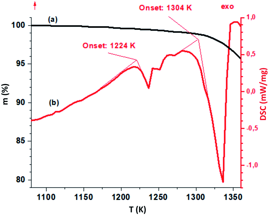 | ||
| Fig. 4 TGA-(black line) and DSC-curves (red) for the LiGaS2 crystal. The heating rate is 10 K min−1 in a helium atmosphere. | ||
2.3. Temperature dependences in XRD
Fig. 5 shows the temperature dependences in the range of 280–750 K for the lattice parameters a, b, c and the volume of the unit cell V in LiGaS2 (blocks (a–d), respectively). It can be seen that all the lattice parameters increase monotonically with increasing temperature, as in the case of other crystals of the LiBC2 family with an orthorhombic structure (LiInS2, LiInSe2 LiGaSe2). The thermal expansion coefficients ΔL/(L × ΔT) for LiGaS2 are aX = 8.13 × 10⁻⁶, aY = 18.9 × 10⁻⁶, and aZ = 6.83 × 10⁻⁶. An important advantage of such crystals in comparison with crystals with the chalcopyrite structure is a less pronounced anisotropy in the thermal expansion coefficients along different crystallographic directions. In the AgGaS2, AgGaSe2, and ZnGeP2 crystals with the chalcopyrite structure, the thermal expansion coefficients along and across the optical axis are quite significant in magnitude, but on the other hand they have a different sign. As a result, when the temperature changes a crystal expands in one direction and contracts in the other. For example, for silver thiogallate, α (⊥c) = 12.5 × 10⁻⁶ and α (‖c) = −13.2 × 10⁻⁶, and this significantly complicates the growth of large crystals of high optical quality.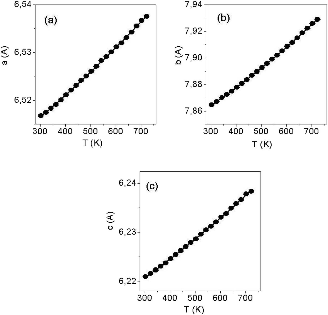 | ||
| Fig. 5 Thermal dependences of cell parameters a (a), b (b) and c (c) of LiGaS2. | ||
To clarify the situation with a possible phase transition near 1224 K, the XRD studies of the LiGaS2 sample was performed with gradual heating until the temperature of the assumed phase transition was reached (Fig. 6). It was found that there is no phase transition, and an additional phase appears above 980 K, the amount of which increases to 1180 K and decreases above 1230 K with the restoration of the reflex intensities of the original LiGaS2 phase. From Fig. 6, it can be seen that the detected compound is stable in the temperature range of 980–1230 K. A comparison of the position of the diffraction peaks (Fig. S2 in ESI†) of the detected additional phase and the LiGaO2 compound suggests that the new phase is an oxygen-containing compound.14 A slight shift of the reflexes towards lower values of 2Theta indicates an increase in the lattice parameters, which may be due to partial sulfur substitution with O2− anions and the formation of an isostructured LiGaO2−xSx compound of rhombic symmetry (Pna21). Thus, the thermal effect detected on the DSC curve indicates the dissolution of LiGaO2−xSx in LiGaS2 in a certain temperature range.
 | ||
| Fig. 6 A series of X-ray diffractograms of the LiGaS2 sample obtained in a high vacuum (∼5 × 10⁻⁴ mBar) at temperatures in the range of 780–1230 K. The dotted line shows the most intense reflexes related to the oxygen-containing phase. On the diffractogram obtained at T = 1080 K, all reflexes related to this phase, supposedly LiGaO2−xSx, are marked with asterisks. | ||
2.4. Thermal diffusivity and thermal conductivity in LiGaS2
To measure the thermal conductivity, one of the non-stationary methods was used, in which the thermal diffusivity is directly measured, and then calculated taking into account the known values of the heat capacity and density. The thermal diffusivity δ is a physical quantity that characterizes the rate of change (equalization) of the temperature of a substance in nonequilibrium thermal processes. Numerically, the thermal conductivity is equal to the ratio of the thermal conductivity to the specific heat capacity at constant pressure cp. The thermal conductivity of the crystal χ can be calculated using the following formula:15| χ = δ × cp × ρ, | (1) |
Measurements at a given temperature T were carried out in a series of two “flashes” of the laser after the sample was thermostated. The interval between the “flashes” was 3 minutes. Since LiGaS2 is transparent at the wavelength of the laser light source generation, the samples were previously coated with a layer of graphite on both ends to increase the absorption capacity of the surfaces. The measurement error of α for solid samples on the LFA-427 unit is 2–5%, depending on the temperature. The obtained values of thermal diffusivity for LiGaS2 and the values of thermal conductivity calculated from them according to the formula (1) for various crystallographic directions (X, Y, Z), as well as the temperature dependence in the range of 20–300 °C for χZ, are presented in Table 2 and Fig. 7. The calculations used the values of the specific heat capacity cp at 300 and 460 K for LiGaS2: 90.08 and 98.6 J mol−1 K−1, respectively, as well as molecular mass M = 140.78 g mol−1 (ref. 17) and density (specific gravity) 2.94 g cm−3.1 The thermal expansion of the samples was not taken into account. Previously, based on the data of vibrational spectroscopy, the values of thermal conductivity at 300 K for LiGaS2 were estimated in the range of 6 ÷ 8 W (m−1 K−1).16 The values of the thermal conductivity χ, measured by us experimentally, were even about 25% higher: 8.440, 9.108 and 10.058 W mK−1 along X, Y, Z, respectively. The maximum values of χ are obtained for room temperature along Z direction. In Fig. 7a one can see that with an increase in temperature to 580 K, the thermal conductivity decreases by more than 2 times. Also for this sample, the thermal conductivity during cooling in the region of 473 K was measured and a good agreement with the data obtained during heating was established. Such behavior of thermal conductivity as a function of temperature is characteristic of the dominant lattice (phonon) contribution to the total thermal conductivity.
| Crystallographic direction, mode | T, K | δ for LiGaS2, mm2 s−1 | χ for LiGaS2 W (m−1 K−1) | χ for LiInS2, W (m−1 K−1) | χ, for AgGaS2, W (m−1 K−1) |
|---|---|---|---|---|---|
| X | 296.5 | 4.662 | 8.440 | 6.2 (ref. 16) | 1.5 (ref. 16) |
| Y, heating | 296.7 | 5.031 | 9.108 | 6.0 (ref. 16) | 1.5 (ref. 16) |
| 371.7 | 3.725 | 7.141 | |||
| 470.7 | 2.635 | 5.222 | |||
| 571.9 | 2.061 | 4.267 | |||
| Y, cooling | 573.6 | 2.035 | 4.213 | ||
| 473.3 | 2.659 | 5.345 | |||
| Z | 296.6 | 5.556 | 10.058 | 7.6 (ref. 16) | 1.4 (ref. 16) |
 | ||
| Fig. 7 Thermal conductivity for chalcogenides: (a) LiGaS2 along X, Y and Z directions at room temperature and temperature deendence for χZ in the 300 to 557 K range. Arrows indicate heating or cooling regime. (b) Comparison of values for commercial AgGaS2, AgGaSe2 and for crystals of the LiBC2 family with B = In, Ga and CS, Se. | ||
Fig. 7b compares the thermal conductivity values for commercial AgGaS2 and AgGaSe2, and the values for members of the LiBC2 family, for which the thermal conductivity has so far been measured experimentally. As you know, the thermal conductivity of materials or energy transfer is determined by elastic vibrations (phonons), and above all by their energy. In turn, the latter is determined by the mass of the participating ions and the energy of the phonons increases with decreasing ion mass. As a consequence, the thermal conductivity is relatively low in silver thiogallate and, as our experiments show, it is almost 7 times higher in lithium thiogallate. Thus, LiGaS2 effectively implements energy dissipation under local heating in the laser scheme and the crystal has a high optical damage threshold. The literature provides LDT values of 34, 40, and more than 240 MW cm−2 at pumping with 1.064 nm, 15 ns pulses for AgGaS2, LiInS2, and LiGaS2, respectively.16
2.5. Thermooptic effects in LiGaS2
Fig. 8 shows the temperature dependence of the birefringence measured in a wide range from 373 K to 1173 K. Features at temperatures above 870 K are associated with the degradation of the polished surface of the crystals: at a higher temperature, the surface becomes matte. The crystal is vaporized, as a result of which the upper surface is covered with plaque flakes, while the lower surface remains unchanged. It can be seen that the birefringence measured at 400 nm increases monotonically and approximately linearly with an increase in temperature from 100 to 950 K. Curves 1–3 are smooth and no special features are detected: thus, there are no phase transitions in this range.
 | ||
| Fig. 8 Temperature dependences of the birefringence of LiGaS2 at a wavelength of about 400 nm: (1) Δnb, (2) Δnc, (3) Δna. | ||
Fig. 9 shows the birefringence dependence of Δnb, Δnc and Δna. for a biaxial LiGaS2 crystal from the wavelength in the range of its transparency. It can be seen that the birefringence values Δna and Δnc are quite close to each other (∼0.04), but they are both quite far from Δnb. In this case, the dependence Δnb = f(T) passes through zero twice, i.e. there are two so-called isotropic points. Fig. 10 shows the transmission spectra for a LiGaS2 plate located between two polaroids when they are crossed (curve (1)) and when the polaroids are parallel (2). In this case, the spectra show characteristic anomalies in the visible region of the spectrum in the form of a narrow dip (1) and in the form of a narrow passband (2) at the same wavelength. A similar feature was previously observed in some anisotropic crystals in the presence of natural or induced gyrotropy at the wavelength of the isotropic point. Examples of such crystals are double single crystals of CdS, CdSe, ZnO, AgJ, MnF2, Al2O3, ZnTe, and mixed compounds based on these crystals.18 Of the triple chalcogenides used in nonlinear optics, such narrow-band filtration was previously observed in AgGaS2 and AgGaSe2 crystals with a chalcopyrite structure (symmetry-42m).19
 | ||
| Fig. 9 Dependence of the birefringence Δn on the wavelength for LiGaS2. The arrows show two isotropic points, where Δn = 0. | ||
 | ||
| Fig. 10 Transmission spectra for (100) LiGaS2 plate with a thickness of 5 mm placed between crossed (1) and parallel (2) film polarizers. | ||
At room temperature, for the (100) LiGaS2 plate, both features are located at 451.5 nm, and they correspond to one of the isotropic points. Another similar feature is expected in the mid-IR, at about 7 μm. It is established that the position of the described line significantly depends on the temperature. Fig. 11 shows a set of transmission lines for the case of crossed polarizers, when the temperature of the LiGaS2 crystal varied in the range from 77 to 550 K (points 1–14). At the same time, the position of the line is shifted from 430 to 490 nm, respectively.
 | ||
| Fig. 11 Transmission spectra for a (100) LiGaS2 plate 5 mm thick placed between the crossed polarizers. Spectra were measured at fourteen different temperatures in the temperature range of 77 K (curve (1)) to 550 K (14). | ||
Fig. 12 shows the dependence of the position of the isotropic point in the visible region of the spectrum as a function of temperature. This dependence is well approximated by the dependence  , where the parameter values are A = 429.75, B1 = 0.02, and B2 = 1.7 × 10⁻⁴. The value of the line width at half-height gradually changes from 2.4 at 77 K to 5.4 nm at 550 K with a spectral resolution of about 0.5 nm. Thus, the LiGaS2 plate in combination with two polarizers can be used as a narrow-band optical filter, smoothly tunable by changing the temperature of the crystal (Fig. 13).
 | ||
Fig. 12 The position of the isotropic point as a function of temperature. The dependence is approximated by the polynomial  , where the parameter values are A = 429.75, B1 = 0.02, and B2 = 1.7 × 10⁻⁴. , where the parameter values are A = 429.75, B1 = 0.02, and B2 = 1.7 × 10⁻⁴. | ||
 | ||
| Fig. 13 Absorption spectra for LiGaS2 in the region of the fundamental absorption edge, measured at 12 different temperatures in the range from 77 to 300 K and presented in coordinates (αhν)2 = f(hν) (Tauc plot). The insert shows the temperature dependence for the band gap in LiGaS2. The points are obtained experimentally, while the line shows the result of the approximation in accordance with the Varshni equation.21 | ||
Fig. 14 shows such constructions for 12 different temperatures in the range of 77–300 K. It can be seen that the absorption edge shifts towards lower energies as the temperature increases. In this case, the band gap Eg, determined by the intersection of the approximating line with the abcissa axis, increases from 4.03 eV at 77 K to 3.88 eV at 300 K. The insert in Fig. 14 shows the temperature dependence for Eg. We found that it is well described by the semi-empirical Varshni equation:21
| Eg(T) = E0 − α1T2/(T + β1) | (2) |
 | ||
| Fig. 14 PL spectra recorded at T = 80 K, at 300 nm (1) and 375 nm (2) excitation for LiGaS2 annealed in vacuum. The insert shows the room temperature PL patterns obtained at UV excitation with 300 nm light (upper image with orange emission) and 375 nm (lower image with blue PL). | ||
The temperature dependence for the PL glow in the main bands is shown in Fig. 15. For both PL bands temperature dependence is well described by the Mott model for two recombination channels, one radiative and one non-radiative, from the relaxed excited state.23 Here the temperature dependence of quantum efficiency η follows the expression:
η(T) ≈ 1/(1 + τRν0![[thin space (1/6-em)]](https://www.rsc.org/images/entities/char_2009.gif) exp(−ΔE/kT)) exp(−ΔE/kT))
| (3) |
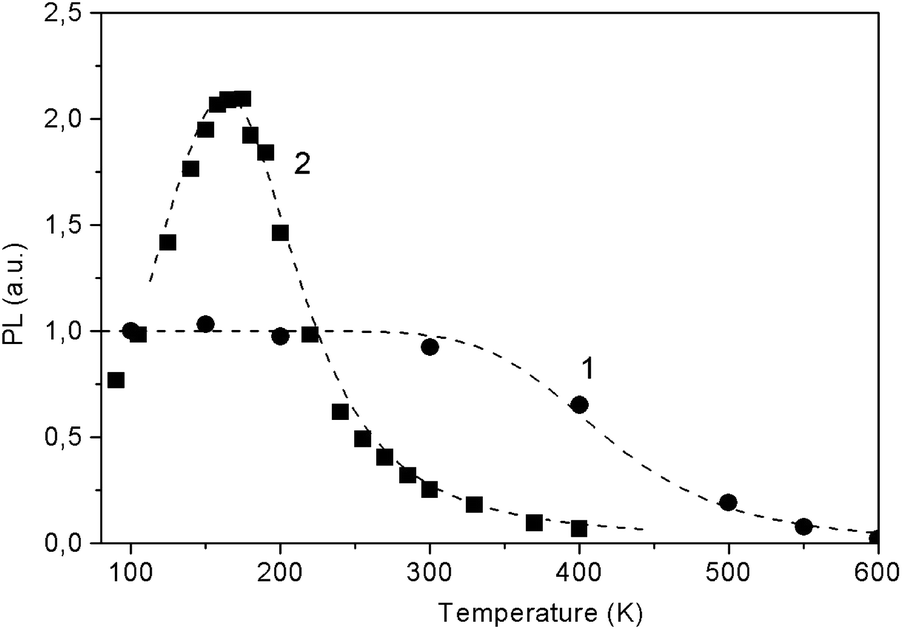 | ||
| Fig. 15 The temperature dependence of the integral PL in the bands of about 600 nm (1) and 425 nm (2) in LiGaS2 at excitation of 300 and 375 nm, respectively. The dots represent the experimental data, while the dotted curves show the results of calculations according to eqn (3) with the parameters ΔE = 0.14 eV, τRν0 = 4 × 10³ (1) and ΔE = 0.35 eV, τRν0 = 1.7 × 10⁴ (2). | ||
Fig. 15 shows the experimental points and the results of their approximation for the orange and blue glow (dotted curves). For the blue glow of VS, the parameters ΔE = 0.35 eV and preexponential factor τRν0 = 1.7 × 10⁴ are well suited, while for the orange glow of STE, the parameters are ΔE = 0.14 eV and τRν0 = 4 × 10³. In the case of STE, there is an initial stage of PL rise with an activation energy of ΔE1 ∼ 0.02 eV, which indicates the need to overcome a small activation barrier for exciton self-localization. Thus, in the case of LiGaS2, it is possible to directly cause intense blue room-temperature PL by special post-growth annealing crystal in vacuum. At 365 nm excitation, the quantum yield of PL in LGS is estimated relative to Rhodamine 640 with a quantum yield η close to unity. At room temperature, the values of η are about 0.1 for the blue luminescence of F-centers and 0.0095 for the glow of STE. As can be seen from Fig. 15, the intensity of blue PL flares increases about 10 times when the temperature drops to 180 K, whereas with a further decrease in temperature, some weakening of the PL is observed. A completely different behavior is demonstrated by a weaker exciton PL: it is constant in the low-temperature range and quenched above room temperature. Low values of η make it difficult to widely use LGS at room temperature, but at 180 K the quantum yield of the blue PL is close to unity. Nevertheless, the analysis of the PL spectra allows us to obtain valuable information about the conditions for growth or annealing crystals, as well as about the state of point defects. It should be noted that a similar (in the blue region) PL associated with F-centers is also observed in LiInS2.
To date, this is the only known case of bright photoluminescence at room temperature in the visible region of the spectrum among the crystals of ternary chalcogenides, including the LiBC2 family. The crystal is considered as promising for use in various optical devices including active media for lasers and light sources.
 | ||
| Fig. 16 TL curve for LiGaS2 after 365 nm excitation at 80 K and the results of deconvolution into 8 components (shown in thin lines). The resulting parameters for the corresponding capture centers are shown in the Table 3 below. | ||
The shape of TL peak is described by the following expression:24
 | (4) |
| NN | Peak maximum position, K | Thermal activation energy, eV | Preexponential coefficient, s−1 |
|---|---|---|---|
| 1 | 115 | 0.23 | 108 |
| 2 | 144 | 0.31 | 3 × 10¹⁰ |
| 3 | 156 | 0.45 | 3 × 10¹² |
| 4 | 190 | 0.36 | 108 |
| 5 | 217 | 0.44 | 3 × 10⁸ |
| 6 | 256 | 0.67 | 1012 |
| 7 | 283 | 0.72 | 1011 |
| 8 | 324 | 0.90 | 1012 |
It can be seen that the TL glow is localized mainly in the low-temperature region of 140–240 K: exactly where the peak in the temperature dependence of the STE luminescence is observed (Fig. 15). It is possible that the traps are involved in the process of radiative recombination of STE maybe as a result of intermediate localization of charge carriers on traps.
![[4 with combining macron]](https://www.rsc.org/images/entities/char_0034_0304.gif) 2d) which are not pyroelectrics. The absence of PEL at temperature greater than 440 K is the result of an increase in electrical conductivity as temperature grows. This increase in conductivity promotes the leak of the pyroelectric charge and the break-down probability becomes smaller. The PEL effect indicates a relatively low LiGaS2 conductivity and, in turn, a low concentration of electrically active defects. PEL intensity decreases until it completely disappears when the crystals are illuminated or after their preliminary illumination: this is due to an increase in electrical conductivity as a result of such processing and charge runoff. It is assumed that PEL can also occur as a result of local heating of a nonlinear crystal during operation in a laser scheme and be one of the mechanisms of laser damage to crystals.
2d) which are not pyroelectrics. The absence of PEL at temperature greater than 440 K is the result of an increase in electrical conductivity as temperature grows. This increase in conductivity promotes the leak of the pyroelectric charge and the break-down probability becomes smaller. The PEL effect indicates a relatively low LiGaS2 conductivity and, in turn, a low concentration of electrically active defects. PEL intensity decreases until it completely disappears when the crystals are illuminated or after their preliminary illumination: this is due to an increase in electrical conductivity as a result of such processing and charge runoff. It is assumed that PEL can also occur as a result of local heating of a nonlinear crystal during operation in a laser scheme and be one of the mechanisms of laser damage to crystals.
 | ||
| Fig. 17 Temperature dependence of spontaneous luminescence in LiGaS2 in the cooling (a) and heating (b) modes. | ||
3. Conclusions
(1) Large LiGaS2 crystals with a length of up to 50 mm, a diameter of up to 20 mm, of high optical quality were grown.(2) DSC shows anomalies of about 1224 K, at a temperature below the melting point (1304 K ± 5). In this case, the lattice parameters and birefringence increase smoothly and monotonically with increasing temperature, which indicates the absence of phase transitions in LiGaS2. Anomalies around 1224 K are associated with the appearance of inclusions of the type LiGaO2−xSx.
(3) The thermal conductivity χ was measured for LiGaS2: the values of 8.44 (X), 9.11 (Y), and 10.05 (Z) W (m−1 K−1) obtained at 300 K are the highest among the crystals of the LiBC2 family where B = In, Ga, CS, Se, Te. The thermal conductivity decreases with increasing temperature in the range of 300–600 K in accordance with the model of the dominant lattice mechanism.
(4) The isotropic points in the dispersion characteristics n = f(λ) for LiGaS2 are revealed. The possibility of using the crystal in narrow-band optical filters smoothly tunable by changing crystal temperature is demonstrated. The position of the transmission line changes from 430 to 490 nm when heated from 77 to 550 K, while the FWHM values increase from 2.4 to 5.4 K. Calibration curves are proposed.
(5) The Tauc analysis shows that band-to-band transitions are determined by direct allowed electronic transitions. The band gap Eg is 4.02 and 3.93 eV at 80 and 300 K, and the dependence Eg = f(T) is described by the semi-empirical Varshni law.
(6) In the PL spectra for LiGaS2, the most common is the low-temperature glow of self-trapped excitons. Post-growth annealing in vacuum produces anionic VS vacancies and corresponding intense blue PL at room temperature.
(7) The thermoluminescence curves are analyzed, and the parameters of the charge carrier capture centers with energies in the range of 0.2–0.9 eV are estimated.
(8) LiGaS2 crystals exhibit pyroluminescene in the range of 80–350 K. This is consistent with the established XRD symmetry of mm2. The latter belongs to one of the 10 crystallographic groups with a non-zero vector of spontaneous polarization.
4. Experimental section
4.1. Crystal growth
LiGaS2 single crystals were grown by the Bridgman–Stockbarger method in a two-zone vertical furnace. The upper and lower parts of the furnace were separated by a diaphragm made of thermal insulation material. The temperature in the melt with an accuracy of ±0.1 °C was maintained at 1423 K, which is ∼100 K higher than the melting point of LiGaS2. The axial temperature gradient was about ∼2° mm−1. The rate of the ampoule lowering varied in the range of 2–10 mm per day. Ga and S of 99.999% purity and Li of 99.9% purity were used as initial chemical reagents for crystal growth. The charge was poured into an ampoule made of glass graphite, which, in turn, was sealed in a quartz ampoule. This design made it possible to avoid chemical interaction between the Li and the walls of the quartz container.4.2. X-ray diffraction studies
Powder X-ray diffraction data were collected on a PANalytical X'Pert PRO diffractometer with a solid state detector PIXcel using Cu Kα radiation over the 2θ range 15–105°. An Anton Paar HTK 1200N camera was used for the high-temperature measurements. The powder diffraction data of LiGaS2 for Rietveld analysis was collected at room temperature with a Bruker D8 ADVANCE powder diffractometer (Cu-Kα radiation) and linear VANTEC detector. The step size of 2θ was 0.016°, and the counting time was 1.5 s per step. The 2θ range of 10–70° was measured with 0.6 mm divergence slit, but 2θ range of 70–140° was measured with 2 mm divergence slit. Rietveld refinement was performed by using TOPAS 4.2 (ref. 26) which accounts esd's of each point by special weight scheme.Larger slits allow noticeably increase intensity of high-angle peaks without loss of resolution because the high-angle peaks are broad enough to be not affected by bigger divergence beam. The esd's σ(Ii) of all points on patterns were calculated using intensities Ii: σ(Ii) = Ii1/2. The intensities and obtained esd's were further normalized: Ii norm = Ii × 0.6/(slit width), σnorm(Ii) = σ(Ii) × 0.6/(slit width), taking into account actual value of divergence slit width which was used to measure each particular intensity Ii, and saved in xye-type file. So transformed powder pattern has usual view in whole 2θ range 10–140°, but all high-angle points have small esd's. Difference Rietveld plot of LiGaS2 is given in Fig. S1 in ESI.†
4.3. Optical properties
Absorption spectra for LiGaS2 were measured using a UV-2501PC Shimadzu spectrometer in the UV to near IR region and a Fourier transform spectrometer Infralum FT-801, in the mid IR. Transmission spectra at different temperatures and temperature dependences in the heating or cooling mode were measured using a metal vacuum cryostat with fused quartz windows. The transmission spectrum for a 2 mm thick LiGaS2 plate measured at room temperature is shown in Fig. 3. The transparency range is 0.326–12.7 μm. Transmission spectra were obtained at 14 different temperatures in the range of 80–350 K, and in each case, the shape of the fundamental absorption edge was analyzed following Tauc20 to determine the mechanism of band-to-band electronic transitions. In the study of pyroluminescence (PEL) and thermoluminescence (TL), the rate of change in temperature β in the range of 80–600 K during heating or cooling was maintained at 30° min−1 and was regulated using liquid nitrogen and an ohmic heater controlled from a temperature controller. The isotropic point was detected by characteristic narrow dips/peaks in the transmission spectra when registering the spectral dependence of the transmission of the LiGaS2 sample located between two parallel-tuned or crossed film polaroids, respectively.The photoluminescence (PL) spectra were recorded on diffraction luminescence spectrometer SDL1 with excitation from a 1 kW Xe lamp through a diffraction MDR2 monochromator. A cooled FEU83 photomultiplier sensitive up to 1.2 μm (1.03 eV) was used to detect the PL emission. The thermoluminescence (TL) curves were obtained by recording the glow of the crystal during its heating at a constant rate of 30 deg. per min after irradiation at a temperature of 80 K.
The birefringence measurements were carried out in the temperature range of 90–950 K with the use of an Axioskop-40 polarization microscope and Linkam LTS 350 and TS1500 heating stages. Birefringence was measured to an accuracy of ±0.00001 by the Berek compensator method with the use of a Leica instrument.
4.4. Thermophysical measurements
Conflicts of interest
There are no conflicts to declare.Acknowledgements
Crystal growth and investigation of physical properties were supported by Russian Science Foundation, Russia (#19-12-00085). Spectroscopic study was performed on a state assignment of the Institute of Geology and Mineralogy, Siberian Branch of Russian Academy of Sciences Russia and Ministry of Science and Higher Education, Russia. Measurements of thermal conductivity were funded by RFBR and Novosibirsk region (grant #20-42-543006\20).References
- D. Nikogosyan, Nonlinear Optical Crystals: A Complete Survey, Springer Science + Business Media, Inc., N.-Y, 2005 Search PubMed
.
- L. Isaenko, A. Yelisseyev, S. Lobanov, A. Titov, V. Petrov, J.-J. Zondy, P. Krinitsin, A. Merkulov, V. Vedenyapin and J. Smirnova, Cryst. Res. Technol., 2003, 38, 379 CrossRef CAS
- H.-M. Zhou, L. Xiong, L. Chen and L.-M. Wu, Angew. Chem., Int. Ed., 2019, 58, 9979 CrossRef CAS PubMed
- L. Isaenko, I. Vasilyeva, A. Merkulov, A. Yelisseyev and S. Lobanov, J. Cryst. Growth, 2005, 275, 217 CrossRef CAS
- V. Petrov, A. Yelisseyev, L. Isaenko, S. Lobanov, A. Titov and J.-J. Zondy, Appl. Phys. B, 2004, 78, 543 CrossRef CAS
-
(a) A. Tyazhev, V. Vedenyapin, G. Marchev, A. Yelisseyev, L. Isaenko, D. Kolker, M. Starikova, S. Lobanov, V. Petrov and J.-J. Zondy, Opt. Mater., 2013, 35, 1612 CrossRef CAS
-
(a) G. Boyd, H. Kasper and J. McFee, IEEE J. Quantum Electron., 1971, 7, 563 CrossRef CAS
-
(a) A. Yelisseyev, Z. S. Lin, M. Starikova, L. Isaenko and S. Lobanov, J. Appl. Phys., 2012, 111, 113507 CrossRef
-
(a) V. Vedenyapin, A. Boyko, D. Kolker, L. Isaenko, S. Lobanov, N. Kostyukova, A. Yelisseyev and V. Petrov, Laser Phys. Lett., 2016, 13, 115401 CrossRef
- L. Isaenko, A. Yelisseyev, S. Lobanov, P. Krinitsin, V. Petrov and J.-J. Zondy, J. Non-Cryst. Solids, 2006, 352, 2434 CrossRef
- V. Drebushchak, L. Isaenko, S. Lobanov, P. Krinitsin and S. Grazhdannikov, J. Therm. Anal. Calorim., 2017, 129, 103 CrossRef CAS
- J. Leal-Gonzalez, S. S. Melibary and A. J. Smith, Acta Crystallogr., Sect. C: Struct. Chem., 1990, 46, 2017 CrossRef
- M. Marezio, Acta Crystallogr., 1965, 18, 481 CrossRef CAS
- G. M. Kuz’micheva, V. B. Rybakov, A. V. Gaister and E. V. Zharikov, Inorg. Mater., 2001, 37, 281–285 CrossRef
- R. Berman, Thermal conduction in solids, Clarendon Press, 1976 Search PubMed
-
(a) L. Isaenko, A. Yelisseyev, S. Lobanov, P. Krinitsin, V. Petrov and J.-J. Zondy, J. Non-Cryst. Solids, 2006, 352, 2434 CrossRef
- Q. Li, J. Wei, H. Sun, K. Zhang, Z. Huang and L. Zhang, Sci. Rep., 2017, 7, 13747 CrossRef PubMed
-
(a) G. H. Henry, Phys. Rev., 1966, 143, 627 CrossRef
-
(a) M. V. Hobden, Acta Crystallogr., Sect. A: Cryst. Phys., Diffr., Theor. Gen. Crystallogr., 1968, 24, 676 CrossRef CAS
- J. Tauc, Mater. Res. Bull., 1967, 3, 37 CrossRef
- Y. P. Varshni, Physica, 1967, 34, 149 CrossRef CAS
- K. S. Song and R. T. Williams, Self-trapped excitons, Springer, 1993 Search PubMed
- B. Henderson and G. F. Imbusch, Optical Spectroscopy of Inorganic Solids, Clarendon, 1989 Search PubMed
- S. W. S. Mc Keever, Thermoluminescence of solids, Cambridge Uni. Press, Cambridge, London, New-York, 1988 Search PubMed
-
(a) A. P. Yelisseyev, L. I. Isaenko and M. K. Starikova, J. Opt. Soc. Am. B, 2012, 29, 1430 CrossRef CAS
- Bruker AXS TOPAS V4: User's Manual, Bruker AXS, Karlsruhe, Germany, 2008 Search PubMed
- NETZSCH Proteus Thermal Analysis v.6.1.0 – NETZSCH-Gerätebau GmbH – Selb/Bayern, Germany, 2013 Search PubMed
-
(a) W. J. Parker, R. J. Jenkins, C. P. Butler and G. L. Abbott, J. Appl. Phys., 1961, 32, 1679 CrossRef CAS
- J. A. Cape and G. W. Lehman, J. Appl. Phys., 1963, 34, 1909 CrossRef
- J. Blumm and J. Opfermann, High Temp. – High Pressures, 2002, 34, 515 CrossRef CAS
Footnote |
| † Electronic supplementary information (ESI) available: Difference Rietveld plot of LiGaS2 (Fig. S1) and tables with fractional atomic coordinates and isotropic displacement parameters (Table S1) and main bond lengths of LiGaS2 (Table S2) are given in the ESI. Comparison of the X-ray diffractograms for LiGaS2 obtained at 1080 K (above) and LiGaO2 is given in Fig. 2S. See DOI: 10.1039/d1ra05698k |
| This journal is © The Royal Society of Chemistry 2021 |