 Open Access Article
Welding partially reduced graphene oxides by MOFs into micro–mesoporous hybrids for high-performance oil absorption†
Lu Sun and
Jun Tang *
*
Department of Polymer Science, Jilin University, Changchun 130012, China. E-mail: chemjtang@jlu.edu.cn
First published on 20th September 2021
Abstract
Partially reduced graphene oxides (PRGOs) with a small number of COOH groups remaining at the edges were interlocked by UiO-66-NH2 nanoparticles into hierarchical porous hybrids (PRGO@UiO-66-NH2) during the synthesis of UiO-66-NH2 in the presence of PRGOs, in which the UiO-66-NH2 nanoparticles provide micropores and the interlocked PRGO skeletons provide mesopores. The peak intensity of the functional groups on the PRGO@UiO-66-NH2 hybrids decrease greatly when compared with the GO@UiO-66-NH2 hybrids and the UiO-66-NH2 nanoparticles, and the number of –COOH at the edge of the PRGOs are approximately 6.3% after reduction, which is confirmed by the FT-IR and XPS results. When the PRGO@UiO-66-NH2 hybrids were embedded in their macropores via hydrogen bonding, melamine foams (MFs) were able to effectively absorb a variety of water-immiscible organic solvents from oil/water biphasic mixtures and, at the same time, suppress water infusion due to Cassie-state surface superhydrophobicity with a water contact angle of 154.2° in air. After 10 cycles, the PRGO@UiO-66-NH2-laden MFs exhibited water contact angles of 148.3°, which indicated that the composite MFs had excellent stability and recycling ability after 10 cycles. The PRGO@UiO-66-NH2-laden MFs had an oil absorption capacity of >10![[thin space (1/6-em)]](https://www.rsc.org/images/entities/char_2009.gif) 000 wt% of the dry mass of absorbents and water absorption capacity of ≈1.76 wt% of the adsorbate, thus highlighting the high absorption selectivity of oil over water.
000 wt% of the dry mass of absorbents and water absorption capacity of ≈1.76 wt% of the adsorbate, thus highlighting the high absorption selectivity of oil over water.
1 Introduction
An oil spill is an example of an anthropogenic disaster with a long-term, severe impact on public health, the environment, and the economy of local communities, in particular where it takes place.1–3 Nowadays small and regular improper disposal of oil into aquatic ecosystem occurs on a regular basis because of the massive amount of transportation of oil across oceans and land, and the increasing use of oil-propelled automobiles. Because of the escalating growth of offshore oil drilling and extraction to meet to the insatiable oil demand worldwide, the occurrence of large-scale oil spills, such as that which happened in the Mexico Gulf in 2010,4 will increase in frequency in the coming years. In addition to traditional methods such as floatation, distillation, solvent extraction and ultrafiltration with large equipment footprints, in recent years there has been rapid development of advanced nanostructured absorbents with a high absorption capacity for oil.5–7 The prevailing oil absorbent design is built on hierarchical porous structures with fairly oleophilic porous surfaces, which are able to not only be readily wetted by oil for effective oil permeation8–10 but also make the surfaces of the porous structures as a whole, superhydrophobic with water contact angles (θw/a) above 150°, which are associated with a large fraction of air trapped in the pores according to the Cassie–Baxter equation.5 The combination of the overall structural surface superhydrophobicity and the surface oleophilicity of individual pores is not easily implemented using conventional polymer sponges or inorganic porous structures coated with low surface energy molecules.11,12In past decades, the progress in materials' science and engineering in preparing oil absorbents is largely driven by two classes of advanced materials, graphene-related and graphene-like two dimensional nanomaterials and metal–organic frameworks (MOFs). In the graphene family, graphene oxides (GOs) rapidly emerge as unique adsorbents thanks to their (quasi-) monolayered non-polar planes of hexagonally arranged carbon atoms with abundant OH groups, and especially COOH groups at edges, which are available for further functionalization.13–15 The MOFs are known as microporous crystalline coordination structures with a high surface area, high porous volume, and high structural stability16–20 and have been extensively exploited as building blocks to functionalize macroporous skeletons by direct growth on the interior macroporous surfaces of polymer sponges21,22 and self-assembly with the aid of polymers23 and inorganic nanoparticles.24–26 An increasing amount of effort has recently been devoted to amalgamating GOs and MOFs into hierarchical porous composites with the aim of joining their unique structural and chemical properties into one composite.27–29 The MOFs can be induced to grow on the surface of GOs by coordination with the metal in the MOFs precursor or by electrostatic attraction. In general, there are two main approaches to synthesizing MOFs and GO composites. One is that the synthesized MOF materials are dispersed in a GO dispersion and the GO@MOF composites are synthesized by electrostatic attraction or a dispersion force. However, the interaction between GOs and MOF materials is weak, which leads to uneven particle mixing. The other is to disperse GOs in the MOF precursor solution, and use the coordination effect between the functional groups on the GO surface and the metal ions to induce the growth of MOFs on the GO surface. In this method, the interaction between the GO and the MOF materials is strong, and the template effect of GO can be used to guide the formation and distribution of MOF particles. Fischer and co-workers recently integrated highly fluorinated GOs and ZIF-8 into a superhydrophobic foam for oil/water separation.30 Because the abundant edge polar groups of GO are beneficial for covalent or non-covalent binding with MOFs to form porous hybrids, they also make the surfaces of the resulting hybrids fairly hydrophilic, thus facilitating infusion of water, which results in poor absorption selectivity of oil over water in applications for oil absorption. Apart from the GOs and MOFs composites, recently reduced GOs (RGOs) and MOF composites have also been fabricated and found to endow better hydrophobicity with the aid of other materials, which leads to more complicated operations in the material preparation process. After reduction of GOs by NaBH4, the resulting RGOs become noticeably hydrophobic but less reactive than GOs due to the loss of COOH groups at the edges.31 Thus, the fully reduced RGOs can barely form strong interactions with the active groups on MOFs and foams,32,33 which may cause difficulties for the adsorption and recovery of crude oil, especially limiting the durability of oil absorbing materials in practical application.
Herein, a simple and effective approach is introduced for preparing a 3D foam of partially reduced GOs (PRGOs) combined with Zr-based MOF-UiO-66-NH2, which unites the challenging needs of superhydrophobicity and structure stability in a single platform. The critical step is that hydriodic acid (HI) was used instead of NaBH4 to reduce the GOs, which yielded PRGOs with a small number of COOH groups remaining at the edge.34,35 When the as-prepared PRGOs were introduced into the reaction media for the synthesis of amine-functionalized UiO-66-NH2, the remaining COOH groups at the edge of the PRGOs were able to form strong coordination bonding with the surface Zr4+ sites of newly grown UiO-66-NH2 nanoparticles to form micro–mesoporous hybrids, denoted as PRGO@UiO-66-NH2. Because of the noticeable hydrophobicity of the PRGOs, the resulting PRGO@UiO-66-NH2 hybrids can effectively repel water. The PRGO@UiO-66-NH2 hybrids were tightly coated onto the macroporous surfaces of the MFs as a result of hydrogen bonding between the former and latter NH2 groups. The resulting PRGO@UiO-66-NH2-laden MFs exhibited an outstanding absorption performance for a broad range of water-immiscible organic solvents, with an absorption capacity in the range of 4900–10![[thin space (1/6-em)]](https://www.rsc.org/images/entities/char_2009.gif) 000 wt% and, at the same time, they possessed Cassie-state superhydrophobic surfaces with a water contact angle in air (θw/a) of 154.2°, and so were able to effectively inhibit the permeation of water into the MFs, and thus ensured a high oil-to-water absorption ratio as high as 50. This universal method of preparing oil-absorbing foams will lead the way for new marine crude oil recovery and water treatment methods.
000 wt% and, at the same time, they possessed Cassie-state superhydrophobic surfaces with a water contact angle in air (θw/a) of 154.2°, and so were able to effectively inhibit the permeation of water into the MFs, and thus ensured a high oil-to-water absorption ratio as high as 50. This universal method of preparing oil-absorbing foams will lead the way for new marine crude oil recovery and water treatment methods.
2 Results and discussion
2.1 Preparation of micro–mesoporous hybrids
The UiO-66-NH2 was chosen for use in the present study because its surface Zr4+ sites were capable of forming strong coordination bonds with the COOH groups on the edges of the PRGOs, and the NH2 groups of its struts were capable of forming hydrogen bonds with the interior macroporous surfaces of the MFs. According to a modified protocol previously reported in the literature,36 the UiO-66-NH2 nanoparticles with sizes of about 50 nm were easily produced via a 24 h incubation of the mixtures of ZrCl4 and 2-amino-1,4-benzenedicarboxylic acid (ABDCA) in N,N-dimethylformamide (DMF) at 120 °C under stirring (Fig. S1, ESI†). Using a modified Hummers' method,37 GOs were produced via oxidation-driven exfoliation of graphite flakes, which were found to be uniform ultrathin sheets (Fig. S2a, ESI†) which possessed abundant COOH groups at the edge, as revealed by X-ray photoelectron spectroscopy (XPS) (Fig. S3a, ESI†). When the synthesis of UiO-66-NH2 was carried out in the presence of GOs, the growing UiO-66-NH2 nanoparticles were expected to ‘stitch’ the edges of the GOs together by coordination between the COOH groups on the GO edge and the Zr4+ sites of the UiO-66-NH2 nanoparticles. The GO@UiO-66-NH2 hybrids were expected to be noticeably hydrophilic, which would be a recognizable technical difficulty for the design of oil absorbents with highly selective absorption of oil over water. However, after the GOs were reduced by NaBH4,38 the resulting hydrophobic RGOs had few COOH groups left at the edge, and thus could hardly form hybrids with the UiO-66-NH2 nanoparticles. To circumvent this, here HI was utilized as the reducing agent to produce the PRGOs.35 Whereas the HI reduction caused little change in morphology between the GOs and the PRGOs (Fig. S2b, ESI†), the fraction of the GO carbon in the form of COOH was reduced from 57.7% for GOs to 6.3% for PRGOs (Fig. S3, ESI†). Because of the small number of COOH groups still remaining at the edges, the resulting PRGOs were expected to interact with UiO-66-NH2 nanoparticles in a way similar to the GOs. To further verify how the number of carboxyl groups changes, Fourier-transform infrared spectroscopy (FT-IR) was applied to determine the content of remaining active groups after reduction by HI (Fig. S4a, ESI†). The concentration of HI was adjusted from 15.7–55 wt% to determine the content of hydroxyl groups on the PRGOs after reduction with different concentrations of HI. The FT-IR spectrum shows that the bending vibration absorptions at 1086 cm−1, 1360 cm−1 and 3600–3800 cm−1 were attributed to the hydroxyl groups at the edge of the PRGOs. The bending bands at approximately 1730–1690 cm−1 were assigned to the C![[double bond, length as m-dash]](https://www.rsc.org/images/entities/char_e001.gif) O on the carboxyl groups and the change of absorption peak position comes from the influence of the hydrogen bonds. The characteristic vibrational signals at 1620 cm−1 should be the C
O on the carboxyl groups and the change of absorption peak position comes from the influence of the hydrogen bonds. The characteristic vibrational signals at 1620 cm−1 should be the C![[double bond, length as m-dash]](https://www.rsc.org/images/entities/char_e001.gif) O on the GOs. The bending bands at approximately 1436 cm−1 and 900 cm−1 were attributed to the hydroxyl groups from the carboxyl groups. It was obvious that all of the peak intensities decreased gradually with the decrease of the concentration of HI. Therefore, to give the composites strong hydrophobicity for the high-performance oil absorption, the PRGOs treated with 55 wt% HI were chosen as the next target for our research. In addition, the PRGO@UiO-66-NH2 hybrids were also characterized by FT-IR. As for the PRGO@UiO-66-NH2 hybrids, the intensity of the characteristic peaks at 1150 cm−1 (stretching vibration of –OH), 1490 cm−1 and 960 cm−1 (bending vibration of –OH on –COOH) and 1560 cm−1 (N–H bending band) were reduced greatly when comparing to those of UiO-66-NH2 and GO@UiO-66-NH2 hybrids, indicating that a small number of COOH groups remaining at the edges were interlocked by the UiO-66-NH2 nanoparticles (Fig. S4b, ESI†). In particular, when the synthesis of UiO-66-NH2 was carried out in the presence of PRGOs, the newly growing UiO-66-NH2 nanoparticles were expected to bind the PRGOs together into PRGO@UiO-66-NH2 hybrids via coordination of the former surface Zr4+ sites with the COOH groups on the edge of the latter (Scheme 1).
O on the GOs. The bending bands at approximately 1436 cm−1 and 900 cm−1 were attributed to the hydroxyl groups from the carboxyl groups. It was obvious that all of the peak intensities decreased gradually with the decrease of the concentration of HI. Therefore, to give the composites strong hydrophobicity for the high-performance oil absorption, the PRGOs treated with 55 wt% HI were chosen as the next target for our research. In addition, the PRGO@UiO-66-NH2 hybrids were also characterized by FT-IR. As for the PRGO@UiO-66-NH2 hybrids, the intensity of the characteristic peaks at 1150 cm−1 (stretching vibration of –OH), 1490 cm−1 and 960 cm−1 (bending vibration of –OH on –COOH) and 1560 cm−1 (N–H bending band) were reduced greatly when comparing to those of UiO-66-NH2 and GO@UiO-66-NH2 hybrids, indicating that a small number of COOH groups remaining at the edges were interlocked by the UiO-66-NH2 nanoparticles (Fig. S4b, ESI†). In particular, when the synthesis of UiO-66-NH2 was carried out in the presence of PRGOs, the newly growing UiO-66-NH2 nanoparticles were expected to bind the PRGOs together into PRGO@UiO-66-NH2 hybrids via coordination of the former surface Zr4+ sites with the COOH groups on the edge of the latter (Scheme 1).
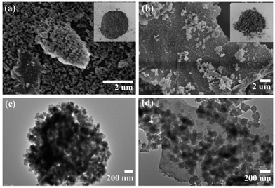
Fig. 1 shows that there was little difference in morphology between the resulting PRGO@UiO-66-NH2 and GO@UiO-66-NH2 hybrids, whereas their color reflected the combination of the constituent UiO-66-NH2 nanoparticles (Fig. S1, ESI†) and GOs or PRGOs (Fig. S2, ESI†). The scanning electron microscopy (SEM) imaging showed that both GO@UiO-66-NH2 and PRGO@UiO-66-NH2 hybrids were obtained as large flat aggregates, whereas either individual UiO-66-NH2 nanoparticles, GOs or PRGOs ultrathin sheets were hardly visible (Fig. 1a, b, S5 and S6, ESI†). Transmission electron microscopy (TEM) images revealed that the ultrathin sheets of GOs or PRGOs were densely bound with UiO-66-NH2 nanoparticles (Fig. 1c and d). Meticulous XPS analysis indicated that the PRGO@UiO-66-NH2 hybrids had less nitrogen content, and that the signal arose solely from the UiO-66-NH2 nanoparticles, rather than the GO@UiO-66-NH2 hybrids (Fig. S7 and Table S1, ESI†). This reflected the fact that the PRGOs had much fewer COOH groups at edge available for complexation with the surface Zr4+ sites of the UiO-66-NH2 nanoparticles than the GOs (Fig. S7, ESI†).
The powder X-ray diffraction (XRD) patterns of the as-prepared GO@UiO-66-NH2 and PRGO@UiO-66-NH2 hybrids revealed peaks at 7.6°, 12.2°, 25.8° and 43.5°, which are characteristic of UiO-66-NH2, thus confirming that there was little impact, by the GOs or PRGOs on the coordination of the Zr4+ ions and ABDCA, on the crystallinity of the resulting UiO-66-NH2 framework (Fig. 2). The mean lattice size (d) of the UiO-66-NH2 nanoparticles formed in the resulting hybrids can be estimated according to Scherrer eqn (1):
d = κλ/β![[thin space (1/6-em)]](https://www.rsc.org/images/entities/char_2009.gif) cos cos![[thin space (1/6-em)]](https://www.rsc.org/images/entities/char_2009.gif) θ θ
| (1) |
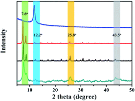 | ||
| Fig. 2 The XRD patterns of the as-prepared GO (blue curve), UiO-66-NH2 nanoparticles (red curve), GO@UiO-66-NH2 hybrids (black curve) and PRGO@UiO-66-NH2 hybrids (green curve). | ||
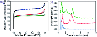
The nitrogen sorption assessment revealed that the as-prepared UiO-66-NH2 nanoparticles exhibited a type-I isotherm which is characteristic of microporous materials, whereas the resulting GO@UiO-66-NH2 and PRGO@UiO-66-NH2 exhibited both type I and type IV isotherms (Fig. 3a), in which the narrow hysteresis loops at the relative pressure (P/P0) in the range of 0.8–1.0 for the GO@UiO-66-NH2 hybrids and 0.4–0.6 for the PRGO@UiO-66-NH2 hybrids signified the coexistence of micropores and mesopores (Fig. S9, ESI†).30 The pore size distributions of the resulting samples in the microporous and mesoporous regions were analyzed by Horvath–Kawazoe (HK) and Barrett–Joyner–Halenda (BJH) methods, respectively. The UiO-66-NH2 nanoparticles obtained in the absence of GOs or PRGOs had micropores in the size range of 0.5–1.5 nm. The GO@UiO-66-NH2 and PRGO@UiO-66-NH2 hybrids displayed both micropores and mesopores. The former micropores (ca. 1.25 nm) were slightly larger than the latter (ca. 0.97 nm), whereas the large fraction of the former mesopores (ca. 3.60 nm) was slightly smaller than that of latter (ca. 3.92 nm). This may be a reflection of the fact that the number of COOH groups on the edge of the PRGO was noticeably smaller than that of the GOs, so after being interlocked by the UiO-66-NH2 nanoparticles, the PRGOs may aggregate into more loosely packed mesoporous structures than the GOs. It should be noted that the micropores sizes of the as-prepared GO@UiO-66-NH2 and PRGO@UiO-66-NH2 hybrids fall in the size range of the mesopores of the UiO-66-NH2 nanoparticles obtained in the absence of GOs or PRGOs. This implied that the micropores of the resulting hybrids were attributed to the UiO-66-NH2 nanocrystals bound between the GOs or PRGOs. The Brunauer–Emmett–Teller method was applied to the surface areas of the as-prepared GO@UiO-66-NH2 and PRGO@UiO-66-NH2 hybrids (Fig. S10, ESI†). When compared with the surface area (966.8 m2 g−1) of the microporous UiO-66-NH2 nanoparticles obtained in the absence of GOs or PRGOs, those of the micro–mesoporous hybrids were noticeably reduced, and the surface area of the GO@UiO-66-NH2 hybrids was 669.1 m2 g−1 and that of the PRGO@UiO-66-NH2 hybrids was 693.4 m2 g−1. These results indicated that the surface Zr4+ sites of the UiO-66-NH2 nanoparticles with the COOH groups on the edges of the GOs or PRGOs, resulted in a big loss in surface porosity of the UiO-66-NH2 nanoparticles, and the loss in the surface area is expected to be larger than that of GOs with more –COOHs on their edges than the PRGOs.
In order to determine the influence of different ratios on the pore size of composite materials, the composites were synthesized with different ratios (20![[thin space (1/6-em)]](https://www.rsc.org/images/entities/char_2009.gif) :
:![[thin space (1/6-em)]](https://www.rsc.org/images/entities/char_2009.gif) 20
20![[thin space (1/6-em)]](https://www.rsc.org/images/entities/char_2009.gif) :
:![[thin space (1/6-em)]](https://www.rsc.org/images/entities/char_2009.gif) 15.5 and 1
15.5 and 1![[thin space (1/6-em)]](https://www.rsc.org/images/entities/char_2009.gif) :
:![[thin space (1/6-em)]](https://www.rsc.org/images/entities/char_2009.gif) 20
20![[thin space (1/6-em)]](https://www.rsc.org/images/entities/char_2009.gif) :
:![[thin space (1/6-em)]](https://www.rsc.org/images/entities/char_2009.gif) 15.5) of GOs/PRGOs, ZrCl4 and ABDCA. The XRD patterns of the as-prepared hybrids with the ratio of 1
15.5) of GOs/PRGOs, ZrCl4 and ABDCA. The XRD patterns of the as-prepared hybrids with the ratio of 1![[thin space (1/6-em)]](https://www.rsc.org/images/entities/char_2009.gif) :
:![[thin space (1/6-em)]](https://www.rsc.org/images/entities/char_2009.gif) 20
20![[thin space (1/6-em)]](https://www.rsc.org/images/entities/char_2009.gif) :
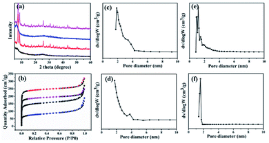
:![[thin space (1/6-em)]](https://www.rsc.org/images/entities/char_2009.gif) 15.5 revealed the presence of peaks at 7.6°, 12.2°, 25.8° and 43.5°, which were similar to those obtained for UiO-66-NH2, thus confirming that was little impact of the GOs or PRGOs on the coordination of Zr4+ ions to form crystals (Fig. 4a). However, for the composites of GOs/PRGOs, ZrCl4 and ABDCA with the ratio of 20
15.5 revealed the presence of peaks at 7.6°, 12.2°, 25.8° and 43.5°, which were similar to those obtained for UiO-66-NH2, thus confirming that was little impact of the GOs or PRGOs on the coordination of Zr4+ ions to form crystals (Fig. 4a). However, for the composites of GOs/PRGOs, ZrCl4 and ABDCA with the ratio of 20![[thin space (1/6-em)]](https://www.rsc.org/images/entities/char_2009.gif) :
:![[thin space (1/6-em)]](https://www.rsc.org/images/entities/char_2009.gif) 20
20![[thin space (1/6-em)]](https://www.rsc.org/images/entities/char_2009.gif) :
:![[thin space (1/6-em)]](https://www.rsc.org/images/entities/char_2009.gif) 15.5, it was obvious that excessive powders of GOs and PRGOs prohibited the formation of the framework of the MOFs. Nitrogen sorption experiments were also made to reveal the pore size distribution as shown in Fig. 4b–f. The composites of GOs/PRGOs, ZrCl4 and ABDCA with the ratio of 20
15.5, it was obvious that excessive powders of GOs and PRGOs prohibited the formation of the framework of the MOFs. Nitrogen sorption experiments were also made to reveal the pore size distribution as shown in Fig. 4b–f. The composites of GOs/PRGOs, ZrCl4 and ABDCA with the ratio of 20![[thin space (1/6-em)]](https://www.rsc.org/images/entities/char_2009.gif) :
:![[thin space (1/6-em)]](https://www.rsc.org/images/entities/char_2009.gif) 20
20![[thin space (1/6-em)]](https://www.rsc.org/images/entities/char_2009.gif) :
:![[thin space (1/6-em)]](https://www.rsc.org/images/entities/char_2009.gif) 15.5 had mesopores in the range of 2–4 nm, whereas the composites of GOs/PRGOs, ZrCl4 and ABDCA with the ratio of 1
15.5 had mesopores in the range of 2–4 nm, whereas the composites of GOs/PRGOs, ZrCl4 and ABDCA with the ratio of 1![[thin space (1/6-em)]](https://www.rsc.org/images/entities/char_2009.gif) :
:![[thin space (1/6-em)]](https://www.rsc.org/images/entities/char_2009.gif) 20
20![[thin space (1/6-em)]](https://www.rsc.org/images/entities/char_2009.gif) :
:![[thin space (1/6-em)]](https://www.rsc.org/images/entities/char_2009.gif) 15.5 only had micropores, and when compared with the GO@UiO-66-NH2 and PRGO@UiO-66-NH2 hybrids they had both micropores and mesopores as mentioned previously. The excessive ZrCl4 and ABDCA would not coordinate with the remaining carboxyl groups on PRGOS, but tended to form MOFs first because of the great disparity of the quantity of active groups, thus forming a microporous structure, and indicating that the necessary conditions for the formation of microporous and mesoporous structures is related to the ratio of the GOs/PRGOs, ZrCl4 and ABDCA.
15.5 only had micropores, and when compared with the GO@UiO-66-NH2 and PRGO@UiO-66-NH2 hybrids they had both micropores and mesopores as mentioned previously. The excessive ZrCl4 and ABDCA would not coordinate with the remaining carboxyl groups on PRGOS, but tended to form MOFs first because of the great disparity of the quantity of active groups, thus forming a microporous structure, and indicating that the necessary conditions for the formation of microporous and mesoporous structures is related to the ratio of the GOs/PRGOs, ZrCl4 and ABDCA.
2.2 Preparation of micro–meso–macroporous foams
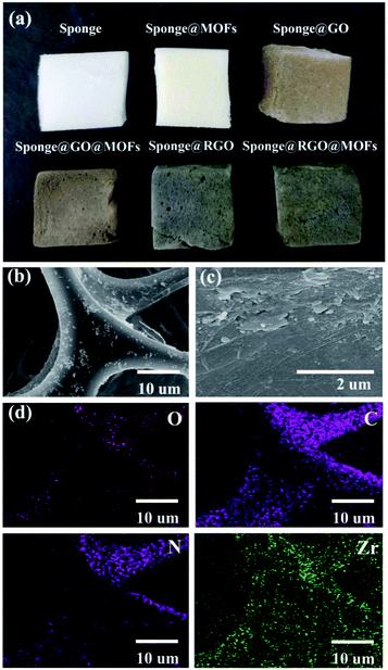
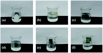
In order to exploit the applicability of the as-prepared PRGO@UiO-66-NH2 hybrids in oil absorption, and especially to determine the impact of their surface wettability on the absorption selectivity of oil over water, commercially available macroporous MFs, shown in Fig. S11 (ESI†), were utilized as hosts to load the as-prepared UiO-66-NH2 nanoparticles, GO@UiO-66-NH2 hybrids and PRGO@UiO-66-NH2 hybrids, because the NH2 groups on the macroporous surfaces of the MFs were expected to form hydrogen bonds with the NH2 groups of the UiO-66-NH2 nanoparticles to secure the loading stability. It should be noted that since their edge OH and COOH groups were also expected to form hydrogen bonds with the NH2 groups on the macroporous surfaces of MFs, GOs and PRGOs, they could adsorb onto the MFs in a similar way with UiO-66-NH2 nanoparticles. After loading, the color of the MF hosts changed from white to a color which was largely dependent on the color of the loaded porous guests (Fig. 5a). Their macroporous structures remained hardly changed with the macroporous surfaces noticeably coated by the functional guests (Fig. 5b, c and S12, ESI†). Energy dispersive X-ray spectroscopy (EDS) mapping further substantiated the uniform surface coverage of the PRGO@UiO-66-NH2 hybrids on the macropores of the MFs (Fig. 5d). To prove the chemical composition of the composite MFs, the FT-IR spectrum was used to prove the chemical composition of the composite MFs. As shown in Fig. S13 (ESI†), the pristine MFs loaded onto the GOs and PRGOs exhibited similar characteristic peaks at 3360 cm−1, 1550 cm−1, 1440 cm−1 and 1320 cm−1 due to the existence of the amine groups. The apparent new peak at approximately 970 cm−1 was attributed to the carboxyl groups at the edge of the GOs/PRGOs. As for the UiO-66-NH2-laden MFs, the GO@UiO-66-NH2-laden MFs and the PRGO@UiO-66-NH2-laden MFs, there was a new peak which appeared at 1650 cm−1 and the peak intensity increased greatly at 3360 cm−1, which was due to the introduction of the –NHCO on UiO-66-NH2 nanoparticles.A moderately hydrophobic solid is both hydrophobic and oleophilic as a result of its surface energy being smaller than the surface tension of water but larger than that of oil.8 The wetting behavior of a solid surface can be noticeably altered provided there are nanostructures molded on the surface according to Wenzel39 and the Cassie–Baxter equations.10 To enhance the oil absorption efficiency and absorption selectivity of oil over water in particular, being able to engineer surface wettability is considered to be the core of novel design of oil absorbents.4 The as-prepared UiO-66-NH2 nanoparticles and GO or PRGO ultrathin sheets, on the macropores of MFs slightly amplified the surface roughness at the nanoscale, whereas their hybrid micro–mesopore introduced nanostructured textures on the surfaces of the MF macropores, which was expected to significantly amplify the surface hydrophobicity as a result of air entrapment in the nanostructures, provided the nanostructured surface was reasonably hydrophobic according to the Cassie–Baxter model.8,40 This accounts for the fact that macroporous MFs loaded with PRGOs or PRGO@UiO-66-NH2 hybrids were able to float well on the surface of water due to the hydrophobicity of PRGOs (Fig. 6e and f). In contrast, the coating of UiO-66-NH2 nanoparticles, GOs, and GO@UiO-66-NH2 was deemed to be sufficiently hydrophilic for effective water wetting, which was the rationale behind the fact that the MFs loaded by these guests readily position themselves underneath the surface of water (Fig. 6b–d).
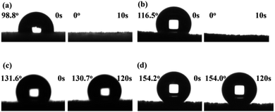
To study the water repellence of the as-prepared composite MFs, water wetting on the foam surfaces in air was measured using the sessile drop method. While the water readily penetrated into pristine MFs with an apparent water contact angle in air (θw/a) of 0° (Fig. S14, ESI†), the composite MFs loaded with GOs or GO@UiO-66-NH2 hybrids display apparent θw/a of 98.8° and 116.3°, respectively, immediately after 2 μL water droplets were placed on top of the MF surfaces (Fig. 7a and b), which was due to air trapping in the mesoporous structures of the GOs and GO@UiO-66-NH2 coatings. However, these large apparent θw/a values rapidly dropped to zero within 10 s, which was indicative of rapid water penetration into the mesoporous coatings on the composite MFs due to the fairly hydrophilic nature of the GOs (Fig. 7a and b). In stark contrast, composite MFs loaded with PRGOs and PRGO@UiO-66-NH2 hybrids exhibited stable apparent θw/a over 120 s of storage in air, and the former θw/a is 131.6° (Fig. 7c) and the latter θw/a is 154.2° (Fig. 7d). The apparent surface superhydrophobicity of PRGO@UiO-66-NH2-laden MFs was expected to enhance the absorption selectivity of oil over water. On the other hand, the oil readily penetrated the PRGO@UiO-66-NH2-laden MFs once it had been placed on top of the MF, and the apparent oil contact angle in air (θo/a) was 0° (Fig. S15, ESI†). In order to determine the hydrophobicity and the stability of the PRGOs-laden MFs after reduction with different concentrations of HI, and the composites of PRGO@UiO-66-NH2-laden MFs, the water repellence of the as-prepared MFs was studied using the sessile drop method. It was observed that the hydrophobicity of the composite MFs was significantly improved when the concentration of HI increased leading to the increase in stability of the composite MFs (Table S2, ESI†). The integration of excellent oil permeation and water repellence in one, therefore means that the PRGO@UiO-66-NH2-laden MFs are promising oil absorbents.
2.3 Assessment of the oil absorption performance of PRGO@UiO-66-NH2-laden MF
The absorption capacity (ηl) of the absorbent for a liquid (l) is calculated by eqn (2):30| ηl = (Mlw − Md)/Md × 100% | (2) |
![[thin space (1/6-em)]](https://www.rsc.org/images/entities/char_2009.gif) 098 wt%) with substantial oil absorption of ηoil of ca. 10
098 wt%) with substantial oil absorption of ηoil of ca. 10![[thin space (1/6-em)]](https://www.rsc.org/images/entities/char_2009.gif) 053 wt%, whereas the MFs loaded with the PRGO@UiO-66-NH2 hybrids exhibited the highest absorption capacity of oil (ηoil of ca. 10
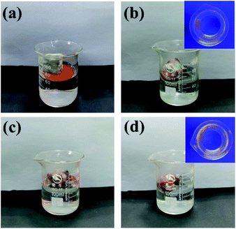
053 wt%, whereas the MFs loaded with the PRGO@UiO-66-NH2 hybrids exhibited the highest absorption capacity of oil (ηoil of ca. 10![[thin space (1/6-em)]](https://www.rsc.org/images/entities/char_2009.gif) 537 wt%) with a negligible absorption of water (ηwater of ca. 176 wt%). Fig. 8b shows that there was nearly a complete blockage of water penetration into the PRGO@UiO-66-NH2-laden MFs, which was evidenced by the barely visible fluorescence of rhodamine B after incubation in rhodamine-stained water. The fluorescence of rhodamine B remained barely visible for PRGO-laden MFs after incubation in the dye solution.
537 wt%) with a negligible absorption of water (ηwater of ca. 176 wt%). Fig. 8b shows that there was nearly a complete blockage of water penetration into the PRGO@UiO-66-NH2-laden MFs, which was evidenced by the barely visible fluorescence of rhodamine B after incubation in rhodamine-stained water. The fluorescence of rhodamine B remained barely visible for PRGO-laden MFs after incubation in the dye solution.
Fig. 9 shows that PRGO@UiO-66-NH2-laden MFs can not only rapidly absorb oil from water within a few seconds but can also easily discharge the absorbed oil by simple squeezing and is then ready for reuse. In the current study it was demonstrated that the MFs could be re-used at least 10 times without noticeable loss in absorption capacity and selectivity. To prove the excellent, recyclability of the PRGO@UiO-66-NH2-laden MFs after 10 cycles of oil adsorption and water repellence, the water contact angles in air of the PRGO@UiO-66-NH2-laden MFs after 10 cycles were measured. As shown in Fig. S16 (ESI†), the PRGO@UiO-66-NH2-laden MFs displayed stable apparent θw/a of 154° before oil absorption (Fig. S16a, ESI†), which was close to the apparent θw/a of 148.3° after 10 cycles (Fig. S16b, ESI†), which indicated that the PRGO@UiO-66-NH2-laden MFs still exhibited surface superhydrophobicity and had excellent recyclability after 10 cycles. As comparison, GO@UiO-66-NH2-laden MFs could absorb the majority but not all of oil from water, and a small amount of oil remained floating on the water (Fig. S17, ESI†). This was attributed to the foams positioning themselves underneath the water surface, and their significant absorption of water and the concomitant leakage of water due to gravity. Fig. 10a shows that PRGO@UiO-66-NH2-laden MFs were able to readily absorb not only VO but also a variety of organic solvents, ranging from hexane, toluene (Tol), dichloromethane, and chloroform (CF), with negligible solubility for diethyl ether (DE), petroleum ether (PE), and ethyl acetate (EA) with tiny but non-negligible solubility in water, and the oil absorption capacity was in the range of 4900 wt% to 10![[thin space (1/6-em)]](https://www.rsc.org/images/entities/char_2009.gif) 000 wt%. Whereas the evaporation of absorbed organic solvents, especially in the case of hexane (Hex) and diether ether may account for an apparent small oil absorption capacity, the oil phase can be reasonably effectively trapped within the hierarchical porous structures of PRGO@UiO-66-NH2-laden MFs, as evidenced by the strong fluorescence of Nile Red after absorption of Nile Red stained organic solvents from water (Fig. 10b). As a reference, the oil absorption ability of various novel existing materials whose hydrophobicity and oil absorption performance are the top 15 so far were compared with the PRGO@UiO-66-NH2-laden MFs fabricated in the research reported in this paper. From Table 1, it can be observed that except for the superhydrophobicity of these novel materials, all of them exhibit excellent superoleophilicity. Because of the superhydrophobicity due to the micro–mesoporous structure, the PRGO@UiO-66-NH2-laden MFs could absorb oil from more than 10 types of organic solvents or oil/water mixtures, and places it among the top three of the existing absorbent materials. It is worth noting that the absorption capacity of the PRGO@UiO-66-NH2-laden MF was superior to those reported in the literature. Except for the intrinsic hydrophobicity of the PRGOs, the micro–mesoporous structure endowed the materials with high pore volumes and high stability which are beneficial to the high oil absorption capacity under the synergistic action of hydrophobic materials and the micro–mesoporous structure. Furthermore, the NH2 groups on the surfaces of the composite MF can form hydrogen bonds with the NH2 groups of the UiO-66-NH2 nanoparticles which secured the loading stability, which was an advantage to improving the recyclability of the PRGO@UiO-66-NH2-laden MFs. The stable entrapment of oil within the PRGO@UiO-66-NH2-laden MFs should offer additional technical benefits to oil removal, because it effectively suppressed the leakage of the oil absorbed therein.
000 wt%. Whereas the evaporation of absorbed organic solvents, especially in the case of hexane (Hex) and diether ether may account for an apparent small oil absorption capacity, the oil phase can be reasonably effectively trapped within the hierarchical porous structures of PRGO@UiO-66-NH2-laden MFs, as evidenced by the strong fluorescence of Nile Red after absorption of Nile Red stained organic solvents from water (Fig. 10b). As a reference, the oil absorption ability of various novel existing materials whose hydrophobicity and oil absorption performance are the top 15 so far were compared with the PRGO@UiO-66-NH2-laden MFs fabricated in the research reported in this paper. From Table 1, it can be observed that except for the superhydrophobicity of these novel materials, all of them exhibit excellent superoleophilicity. Because of the superhydrophobicity due to the micro–mesoporous structure, the PRGO@UiO-66-NH2-laden MFs could absorb oil from more than 10 types of organic solvents or oil/water mixtures, and places it among the top three of the existing absorbent materials. It is worth noting that the absorption capacity of the PRGO@UiO-66-NH2-laden MF was superior to those reported in the literature. Except for the intrinsic hydrophobicity of the PRGOs, the micro–mesoporous structure endowed the materials with high pore volumes and high stability which are beneficial to the high oil absorption capacity under the synergistic action of hydrophobic materials and the micro–mesoporous structure. Furthermore, the NH2 groups on the surfaces of the composite MF can form hydrogen bonds with the NH2 groups of the UiO-66-NH2 nanoparticles which secured the loading stability, which was an advantage to improving the recyclability of the PRGO@UiO-66-NH2-laden MFs. The stable entrapment of oil within the PRGO@UiO-66-NH2-laden MFs should offer additional technical benefits to oil removal, because it effectively suppressed the leakage of the oil absorbed therein.
| Oil absorbents | Preparation methods | θw/a (°) | θo/a (°) | Oil species used for absorption | Absorption capacity (×100%) | Recycle ability | Ref. |
|---|---|---|---|---|---|---|---|
| MOF@rGO sponges | Self-assembles and dip coating | 171 | 0 | Chloroform, toluene ethyl acetate, acetone, silicon oil, bean oil, benzinoform, n-heptane | 14–29 | Good | 27 |
| Conjugated microporous polymers coated sponges | Dip-coating after homocoupling polymerization | 167 | 0 | Vegetable oil, pump oil, octane, dodecane, decane, hexane, phenol, THF, nitrobenzene, chloroform, DMF, 1,2-dichlorobenzene, ethylbenzene, toluene, benzene, DMSO, acetone, ethanol, methanol | 6–23 | Good | 41 |
| Amine-functionalized SiO2/PTFE coated PU sponges | Chemical vapor deposition after dip coating procedure | 165 | 0 | n-Hexane, pentane, heptane, benzene, toluene, silicone oil | 10–12 | Fair | 42 |
| Boron nitride nanosheets | Templating approach | 165 | 0 | Ethanol, toluene, pump oil, used engine oil, ethylene glycol | 20–33 | Good | 43 |
| CNT-coated meshes | Thermal chemical vapor deposition | 163 ± 4 | 0 | Emulsion (diesel, lubricating oil) | n.a. | Good | 44 |
| Polyester fabrics coated with DA-TiO2 and SiO2 | Dip-coating on polyester fabric | 158 | 0 | Hexadecane | n.a. | Good | 45 |
| P2VP-b-PDMS coated meshes | Grafting from then dip-coating | 157.2 | 0 | Gasoline, lubricating oil | n.a. | Good | 46 |
| Spiropyran-containing methacrylate | Copolymerization after solution immersion | 155 ± 27 | n.a. | Silicon oil, pump oil, gasoline, dichloromethane, hexane, DMF, chloroform | 70–154 | Good | 47 |
| PRGO@UiO-66-NH2-laden MFs | In situ synthesis of UiO-66-NH2 in the presence of PRGOs | 154 | 0 | Dichloromethane, hexane, DMF, chloroform, vegetable oil, ether, ethylacetacte, toluene, petroleum ether | 84.5–110.4 | Good | This work |
| Polyester fabrics coated with HFA-TiO2 and SiO2 | Dip-coating on polyester fabric | 152 | 151 | Hexadecane, soybean oil, paraffin oil, diesel | n.a. | Fair | 48 |
| ZIF-8/carbon nitride foam | Fast graphitization and coating | 135 | 0 | Pentane, petroleum ether, hexane, isopropyl ether, decane, ethanol, pump oil, THF, NMP, dichloromethane, chloroform, ethylene glycol | 55–136 | Fair | 49 |
| PNIPAM | In situ polymerization on nylon membranes | 120 ± 30 | 0 | Emulsion, hexane, toluene, lubricating oil, gasoline | 4.6 | Good | 50 |
3 Conclusions
In summary, high-performance 3D foams for use in oil absorption were demonstrated, prepared by a novel strategy utilizing UiO-66-NH2 nanoparticles to weld PRGOs into micro–mesoporous hybrids, where the micropores arise from the periodic frameworks of the resulting UiO-66-NH2 nanoparticles and the mesopores are formed as a result of the UiO-66-NH2 locked aggregation of the PRGOs. After the PRGO@UiO-66-NH2 hybrids were loaded into the macropores of the MF via hydrogen bonding, the whole surface of the resulting composite MFs became superhydrophobic and effectively resistant against penetration of water through the foams. As a result, the present PRGO@UiO-66-NH2-laden MFs displayed excellent absorption performance for a variety of organic solvents with negligible or poor water solubility in water and ultrahigh absorption selectivity of oil over water. Their oil absorption capacity can be as high as 10![[thin space (1/6-em)]](https://www.rsc.org/images/entities/char_2009.gif) 000 wt%, whereas that of water is only ≈1.76 wt% with all the adsorbates tested, which is comparable to the best oil absorption performance of oil absorbents found in literature so far (Table 1). Because of its ease of operation, this approach will lead to new prospects in the development of oil absorbents and, hopefully, stimulate more ingenious design of PRGO@MOF hybrids by taking advantage of the wide spectrum of MOFs currently available to further enhance the oil absorption performance. Furthermore, this work also demonstrates that although they have very few COOH groups at the edge (as low as 6% of carbon), the PRGOs can be readily conjugated with functional nanomaterials in a similar way to how GOs do, which therefore integrates the chemical flexibility of GOs and the physicochemical properties of RGOs in one. As a result, it is hoped that the results of this research will increase the awareness of PRGOs as a promising alternative to RGOs in technical applications especially in catalysis, electrochemical energy storage, electronics, and solar cells.
000 wt%, whereas that of water is only ≈1.76 wt% with all the adsorbates tested, which is comparable to the best oil absorption performance of oil absorbents found in literature so far (Table 1). Because of its ease of operation, this approach will lead to new prospects in the development of oil absorbents and, hopefully, stimulate more ingenious design of PRGO@MOF hybrids by taking advantage of the wide spectrum of MOFs currently available to further enhance the oil absorption performance. Furthermore, this work also demonstrates that although they have very few COOH groups at the edge (as low as 6% of carbon), the PRGOs can be readily conjugated with functional nanomaterials in a similar way to how GOs do, which therefore integrates the chemical flexibility of GOs and the physicochemical properties of RGOs in one. As a result, it is hoped that the results of this research will increase the awareness of PRGOs as a promising alternative to RGOs in technical applications especially in catalysis, electrochemical energy storage, electronics, and solar cells.
Conflicts of interest
There are no conflicts to declare.Acknowledgements
This work was supported by the Science and Technology Development Project of Science and Technology Department of Jilin Province (No. 20180201086GX).References
- E. Barry, J. A. Libera, A. U. Mane, J. R. Avila, D. DeVitis, K. Van Dyke, J. W. Elam and S. B. Darling, Environ. Sci.: Water Res. Technol., 2018, 4, 40–47 RSC.
- M. A. Shannon, P. W. Bohn, M. Elimelech, J. G. Georgiadis, B. J. Mariñas and A. M. Mayes, Nature, 2008, 452, 301–310 CrossRef CAS PubMed.
- R. Das, C. D. Vecitis, A. Schulze, B. Cao, A. F. Ismail, X. Lu, J. Chen and S. Ramakrishna, Chem. Soc. Rev., 2017, 46, 6946–7020 RSC.
- Z. Xu, K. Miyazaki and T. Hori, Adv. Mater. Interfaces, 2015, 2, 1500255 CrossRef.
- J. Ge, H. Y. Zhao, H. W. Zhu, J. Huang, L. A. Shi and S. H. Yu, Adv. Mater., 2016, 28, 10459–10490 CrossRef CAS PubMed.
- H. Guan, Z. Y. Cheng and X. Q. Wang, ACS Nano, 2018, 12, 10365–10373 CrossRef CAS PubMed.
- C. L. Yu, C. M. Yu, L. Y. Cui, Z. Y. Song, X. Y. Zhao, Y. Ma and L. Jiang, Adv. Mater. Interfaces, 2017, 4, 1600862 CrossRef.
- Z. L. Chu, Y. J. Feng and S. Seeger, Angew. Chem., Int. Ed., 2015, 54, 2328–2338 CrossRef CAS PubMed.
- S. Li, J. Huang, Z. Chen, G. Chen and Y. Lai, J. Mater. Chem. A, 2017, 5, 31–55 RSC.
- Q. Ma, H. Cheng, A. G. Fane, R. Wang and H. Zhang, Small, 2016, 12, 2186–2202 CrossRef CAS PubMed.
- M. Tao, L. Xue, F. Liu and L. Jiang, Adv. Mater., 2014, 26, 2943–2948 CrossRef CAS PubMed.
- Y. Zhu, J. Wang, F. Zhang, S. Gao, A. Wang, W. Fang and J. Jin, Adv. Funct. Mater., 2018, 28, 1804121 CrossRef.
- D. Li and R. B. Kaner, Science, 2008, 320, 1170–1171 CrossRef CAS PubMed.
- D. Wu, F. Zhang, H. Liang and X. Feng, Chem. Soc. Rev., 2012, 41, 6160–6177 RSC.
- H. P. Cong, J. J. He, Y. Lu and S. H. Yu, Small, 2010, 6, 169–173 CrossRef CAS PubMed.
- A. Huang, W. Dou and J. Caro, J. Am. Chem. Soc., 2010, 132, 15562–15564 CrossRef CAS PubMed.
- S. Horike, S. Shimomura and S. Kitagawa, Nat. Chem., 2009, 1, 695–704 CrossRef CAS PubMed.
- H. Furukawa, K. E. Cordova, M. O'Keeffe and O. M. Yaghi, Science, 2013, 341, 1230444 CrossRef PubMed.
- J. K. M. Eddaoudi, N. Rosi, D. Vodak, J. Wachter, M. O'Keeffe and O. M. Yaghi, Science, 2002, 295, 469–472 CrossRef PubMed.
- J. L. C. Rowsell and O. M. Yaghi, Microporous Mesoporous Mater., 2004, 73, 3–14 CrossRef CAS.
- Z. Lei, Y. Deng and C. Wang, J. Mater. Chem. A, 2018, 6, 3258–3263 RSC.
- D. Kim, D. W. Kim, O. Buyukcakir, M.-K. Kim, K. Polychronopoulou and A. Coskun, Adv. Funct. Mater., 2017, 27, 1700706 CrossRef.
- T. Kitao, Y. Zhang, S. Kitagawa, B. Wang and T. Uemura, Chem. Soc. Rev., 2017, 46, 3108–3133 RSC.
- S. Zhao, X. Cao, Z. Ma, Z. Wang, Z. Qiao, J. Wang and S. Wang, Ind. Eng. Chem. Res., 2015, 54, 5139–5148 CrossRef CAS.
- G. Huang, Q. H. Yang, Q. Xu, S. H. Yu and H. L. Jiang, Angew. Chem., Int. Ed., 2016, 55, 7505–7509 CrossRef.
- H. Ren, L. Zhang, J. An, T. Wang, L. Li, X. Si, L. He, X. Wu, C. Wang and Z. Su, Chem. Commun., 2014, 50, 1000–1002 RSC.
- J. H. Gu, H. W. Fan, C. X. Li, J. Caro and H. Meng, Angew. Chem., Int. Ed., 2019, 58, 5297–5301 CrossRef CAS PubMed.
- G. H. Yang, D. Q. Zhang, G. Zhu, T. R. Zhou, M. T. Song, L. L. Qu, K. C. Xiong and H. T. Li, RSC Adv., 2020, 10, 8540–8547 RSC.
- R. Heu, M. Ateia and C. Yoshimura, Catalysts, 2020, 10, 711 CrossRef CAS.
- K. Jayaramulu, K. K. Datta, C. Rosler, M. Petr, M. Otyepka, R. Zboril and R. A. Fischer, Angew. Chem., Int. Ed., 2016, 55, 1178–1182 CrossRef CAS PubMed.
- Z. Z. Yang, Q. B. Zheng, H. X. Qiu, J. Li and J. H. Yang, Carbon, 2015, 86, 372 CrossRef.
- L. A. Shi, J. Ge, B. C. Hu, T. Ma, H. Y. Zhao, Y. H. Song, C. Li and S. H. Yu, Nano Res., 2021, 14, 2697–2702 CrossRef CAS.
- T. C. Sun, S. Hao, R. Q. Fan, M. Y. Qin, W. Chen, P. Wang and Y. L. Yang, ACS Appl. Mater. Interfaces, 2020, 12, 56435–56444 CrossRef CAS PubMed.
- M. Qin, Y. Xu, R. Cao, W. Feng and L. Chen, Adv. Funct. Mater., 2018, 28, 1805053 CrossRef.
- J. Ge, L. A. Shi, Y. C. Wang, H. Y. Zhao, H. B. Yao, Y. B. Zhu, Y. Zhang, H. W. Zhu, H. A. Wu and S. H. Yu, Nat. Nanotechnol., 2017, 12, 434–440 CrossRef CAS PubMed.
- Y. Wang, Y. Yu, R. Li, H. J. Liu, W. Zhang, L. J. Ling, W. B. Duan and B. Liu, J. Mater. Chem. A, 2017, 5, 20136–20140 RSC.
- D. Li, M. B. Muller, S. Gilje, R. B. Kaner and G. G. Wallace, Nat. Nanotechnol., 2008, 3, 101–105 CrossRef CAS PubMed.
- L. G. Guex, B. Sacchi, K. F. Peuvot, R. L. Andersson, A. M. Pourrahimi, V. Strom, S. Farris and R. T. Olsson, Nanoscale, 2017, 9, 9562–9571 RSC.
- R. N. Wenzel, Ind. Eng. Chem., 1936, 20, 988–994 CrossRef.
- L. Wen, Y. Tian and L. Jiang, Angew. Chem., Int. Ed., 2015, 54, 3387–3399 CrossRef CAS PubMed.
- A. Li, H. X. Sun, D. Z. Tan, W. J. Fan, S. H. Wen, X. J. Qing, G. X. Li, S. Y. Li and W. Q. Deng, Energy Environ. Sci., 2011, 4, 2062–2065 RSC.
- G. H. Jiang, R. B. Hu, X. G. Xi, X. H. Wang and R. J. Wang, J. Mater. Res., 2013, 28, 651–656 CrossRef CAS.
- W. W. Lei, D. Portehault, D. Liu, S. Qin and Y. Chen, Nat. Commun., 2013, 4, 1777 CrossRef PubMed.
- C. H. Lee, N. Johnson, J. Drelich and Y. K. Yap, Carbon, 2011, 49, 669–676 CrossRef CAS.
- Z. G. Xu, Y. Zhao, H. X. Wang, H. Zhou, C. X. Qin, X. G. Wang and T. Lin, ACS Appl. Mater. Interfaces, 2016, 8, 5661–5667 CrossRef CAS PubMed.
- L. Zhang, Z. Zhang and P. Wang, NPG Asia Mater., 2012, 4, e8 CrossRef.
- H. G. Zhu, S. Yang, D. Y. Chen, N. J. Li, Q. F. Xu, H. Li, J. H. He and J. M. Lu, Adv. Mater. Interfaces, 2016, 3, 1500683 CrossRef.
- Z. G. Xu, Y. Zhao, H. X. Wang, X. G. Wang and T. Lin, Angew. Chem., Int. Ed., 2015, 54, 4527–4530 CrossRef CAS PubMed.
- D. Kim, D. W. Kim, O. Buyukcakir, M.-K. Kim, K. Polychronopoulou and A. Coskun, Adv. Funct. Mater., 2017, 27, 1700706 CrossRef.
- W. F. Zhang, N. Liu, Q. D. Zhang, R. X. Qu, Y. N. Liu, X. Y. Li, Y. Wei, L. Feng and L. Jiang, Angew. Chem., Int. Ed., 2018, 57, 5740–5745 CrossRef CAS PubMed.
Footnote |
| † Electronic supplementary information (ESI) available. See DOI: 10.1039/d1ra05644a |
| This journal is © The Royal Society of Chemistry 2021 |


