 Open Access Article
Creative Commons Attribution 3.0 Unported Licence
Porous ZIF-8@polyacrylonitrile composite beads for iodine capture†
Qiang Yu *a,
Xiaohui Jiang
 *a,
Zhengjun Chenga,
Yunwen Liaoa and
Ming Duan*b
aChemical Synthesis and Pollution Control Key Laboratory of Sichuan Province, China West Normal University, Nanchong, Sichuan, PR China 637009. E-mail: jxh2314508@163.com; 1924163238@qq.com
bState Key Laboratory of Oil and Gas Reservoir Geology and Exploitation, Southwest Petroleum University, Chengdu, Sichuan, PR China 610500. E-mail: mduan@126.com
First published on 10th September 2021
Abstract
The safe and effective capture and storage of iodine from nuclear waste is of great significance in industry. This article reports the preparation of a series of millimeter-sized ZIF-8@polyacrylonitrile composite beads with high specific surface area and porosity by the phase inversion method for iodine capture. The composite beads showed a higher capture capacity (4150 mg g−1) under excess iodine vapor. The amount of iodine adsorbed in the organic solution is also as high as 643 mg g−1, and the adsorption conforms to the Freundlich isotherm and the pseudo-second-order kinetic model. Moreover, composite beads also exhibit higher thermal stability (310 °C). Therefore, ZIF-8@polyacrylonitrile composite beads show great potential as a material for capturing and temporarily storing radioactive iodine.
1. Introduction
With the development of society and economy, nuclear energy has become one of the most important energy sources, and the safe and effective disposal of nuclear waste has become an important issue.1 Radioactive iodine is produced by 235U in nuclear fission.2,3 Radioactive iodine is widely used in nuclear accident detection, discovery of underground pipeline leaks, medical diagnosis, and treatment, etc.4 Every coin has two sides. Iodine is easy to accumulate and accumulate in the thyroid.5 Once the human body takes in a certain amount of radioactive iodine, it will cause human metabolism disorders and seriously affect human health.6–9 Among the radioactive iodine isotopes, the radioactive iodine isotopes that are more harmful to the environment are 129I and 131I. 129I has the characteristics of a high mobility and volatile pollutant with a half-life of 1.52 × 10⁷ years.10 It needs to be captured and reliably stored after a long period of decay. In contrast, 131I is another highly reactive, volatile and short-lived isotope of iodine with a short half-life (about 8.02 d) and requires immediate capture upon release. Many nuclear leaks (such as the Chernobyl and Fukushima accidents) have shown that the volatile iodine is mainly present in the gas in the form of I2.7,11,12 Once radioactive iodine leaks out of the nuclear reactor uncontrollably, it will cause serious damage to the local area and even the world.11 Therefore, the effective and safe disposal of radioactive iodine has become a topic of great significance.As far as we know, the adsorption method has been recognized as one of the most effective methods among the methods of capturing iodine. Currently, a variety of techniques have been developed to capture gaseous radioactive iodine from plant exhaust, including wet scrubbing and solid adsorption.3 Among the iodine capture methods in waste gas, solid adsorption method has the advantages of simple, reliable, non-corrosive, simple design, low maintenance and operation cost; wet cleaning requires the use of corrosive acids or bases, so the solid adsorption method has advantages over wet cleaning.3,13 Nowadays, many materials for capturing iodine have been developed, such as silver-based zeolite,14–16 mordenite,17–20 activated carbon (AC),21–23 porous organic polymer (POPs),24–26 metal–organic framework (MOFs),27–34 etc. Currently, among these methods of capturing iodine, the mainstream method is to use silver-based zeolite to capture iodine.18 However, due to the high cost, low iodine capture and toxicity characteristics of silver-based materials, their large-scale application in practice is restricted. Metal–organic frameworks (MOFs) are crystalline materials with 1D, 2D or 3D structures,35,36 which are formed by the self-assembly of organic ligands and metal ions or clusters through coordination bonds.37–40 Recently, a variety of metal–organic frameworks (MOFs) with high specific surface area and porous structure have been proven to be useful for iodine capture.33,41–44 Zeolitic Imidazolate Framework-8 (ZIF-8) is a kind of porous crystal material with large specific surface area and high porosity formed by self-assembly of zinc ion and 2-methylimidazole coordination, which ensures good iodine vapor capture ability.29,45–48 ZIF-8 also has higher thermal and chemical stability, and its structure is not easily damaged by external influences.48,49 In addition, ZIF-8 is relatively low-cost and easy to manufacture, which is helpful for industrial use. However, powdered ZIF-8 is inconvenient to store and transport, and it is difficult to recycle after use, which limits its industrial application. MOFs-based composite beads or composite membranes can solve these limitations.31,44,50 Kyriakos C. Stylianou et al. reported the use of millimeter-sized HKUST-@polymer beads for iodine capture.27 Wen Zhang et al. studied MOF-808@PVDF composite beads to capture iodine in gas.41 Juan-Tao Jiang et al. reported the removal of iodine in solution by PVDF/ZIF-8 nanocomposite membrane,28 etc.
Based on the above work inspiration, coupled with the excellent performance of ZIF-8, we believe that ZIF-8 may be one of the good options for capturing iodine. Therefore, in this work, we prepared ZIF-8 with methanol as a solvent at room temperature, and used polyacrylonitrile (PAN) as a substrate according to our previous work,18 and combined them to prepare ZIF-8@PAN composite beads. ZIF-8@PAN composite beads overcome the disadvantages of the powder mentioned above, which makes ZIF-8 more mechanically stable during the I2 adsorption process. We conducted a systematic study on the performance of ZIF-8@PAN composite beads to capture iodine, and proposed the mechanism of iodine capture. Our work strongly proves the feasibility of ZIF-8@PAN composite beads to capture iodine, which not only improves the ability of pure ZIF-8 to capture iodine vapor, but is also easy to handle and store, thereby overcoming the disadvantages of powder materials.27 Therefore, ZIF-8@PAN material is one of the attractive composite materials that effectively capture iodine.
2. Experimental section
2.1. Materials
2-Methylimidazole, methanol, iodine (I2), polyvinylpyrrolidone (PVP, K30), polyacrylonitrile (PAN, average Mw 15![[thin space (1/6-em)]](https://www.rsc.org/images/entities/char_2009.gif) 000), dimethyl sulfoxide (DMSO) and cyclohexane were purchased from Shanghai Macklin Biochemical Technology Co., Ltd. Zinc acetate dihydrate ((CH3COO)2Zn·2H2O) was purchased from Tianjin Fuchen Chemical Reagent Factory.
000), dimethyl sulfoxide (DMSO) and cyclohexane were purchased from Shanghai Macklin Biochemical Technology Co., Ltd. Zinc acetate dihydrate ((CH3COO)2Zn·2H2O) was purchased from Tianjin Fuchen Chemical Reagent Factory.
2.2. Preparation of ZIF-8 crystal
All purchased medicines do not require further purification and are used as they are. ZIF-8 crystals were synthesized according to the literature.51,52 In a typical synthesis, first dissolve zinc acetate dihydrate (2.093 g) in methanol (200 mL); then dissolve 2-methylimidazole in methanol (200 mL); finally mix the two solutions at room temperature stir for 5 minutes, then let stand for 24 hours. After that, the supernatant was discarded and centrifuged to obtain a white product, and then methanol was added to repeat the centrifugal washing 3 times, and finally the white product was dried in an oven at 70 °C for 24 hours. The yield of the prepared ZIF-8 sample was 47% (based on Zn).2.3. Preparation of PAN beads and ZIF-8@PAN composite beads
ZIF-8@PAN composite beads are prepared according to different ZIF-8![[thin space (1/6-em)]](https://www.rsc.org/images/entities/char_2009.gif) :
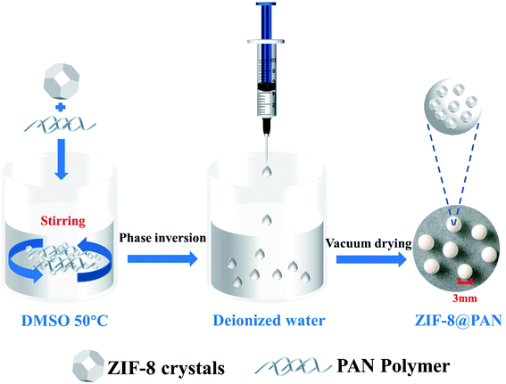
:![[thin space (1/6-em)]](https://www.rsc.org/images/entities/char_2009.gif) PAN weight ratios, and PAN beads do not add ZIF-8. The preparation scheme is as follows (Scheme 1): first, dissolve an appropriate amount of polyacrylonitrile (PAN) in an appropriate amount of dimethyl sulfoxide (DMSO) at 50 °C to form a solution. Secondly, add an appropriate amount of surfactant (PVP) to the solution to make PAN fully stirred until it is clear, which is conducive to the full dispersion of the subsequent ZIF-8. Third, add the corresponding amount of ZIF-8 to the above solution and stir, then ultrasound for 30 minutes, and stir again until fully mixed. After that, the mixed solution was dropped from a pipette into deionized water to form solid beads, and after standing for 10 minutes, washing was repeated several times to remove PVP. Finally, the beads were dried in a vacuum oven at 60 °C for 24 hours. A series of composite beads were prepared with seven different ZIF-8
PAN weight ratios, and PAN beads do not add ZIF-8. The preparation scheme is as follows (Scheme 1): first, dissolve an appropriate amount of polyacrylonitrile (PAN) in an appropriate amount of dimethyl sulfoxide (DMSO) at 50 °C to form a solution. Secondly, add an appropriate amount of surfactant (PVP) to the solution to make PAN fully stirred until it is clear, which is conducive to the full dispersion of the subsequent ZIF-8. Third, add the corresponding amount of ZIF-8 to the above solution and stir, then ultrasound for 30 minutes, and stir again until fully mixed. After that, the mixed solution was dropped from a pipette into deionized water to form solid beads, and after standing for 10 minutes, washing was repeated several times to remove PVP. Finally, the beads were dried in a vacuum oven at 60 °C for 24 hours. A series of composite beads were prepared with seven different ZIF-8![[thin space (1/6-em)]](https://www.rsc.org/images/entities/char_2009.gif) :
:![[thin space (1/6-em)]](https://www.rsc.org/images/entities/char_2009.gif) PAN weight ratios of 1
PAN weight ratios of 1![[thin space (1/6-em)]](https://www.rsc.org/images/entities/char_2009.gif) :
:![[thin space (1/6-em)]](https://www.rsc.org/images/entities/char_2009.gif) 4, 1
4, 1![[thin space (1/6-em)]](https://www.rsc.org/images/entities/char_2009.gif) :
:![[thin space (1/6-em)]](https://www.rsc.org/images/entities/char_2009.gif) 3, 1
3, 1![[thin space (1/6-em)]](https://www.rsc.org/images/entities/char_2009.gif) :
:![[thin space (1/6-em)]](https://www.rsc.org/images/entities/char_2009.gif) 2, 1
2, 1![[thin space (1/6-em)]](https://www.rsc.org/images/entities/char_2009.gif) :
:![[thin space (1/6-em)]](https://www.rsc.org/images/entities/char_2009.gif) 1, 2
1, 2![[thin space (1/6-em)]](https://www.rsc.org/images/entities/char_2009.gif) :
:![[thin space (1/6-em)]](https://www.rsc.org/images/entities/char_2009.gif) 1, 3
1, 3![[thin space (1/6-em)]](https://www.rsc.org/images/entities/char_2009.gif) :
:![[thin space (1/6-em)]](https://www.rsc.org/images/entities/char_2009.gif) 1, 4
1, 4![[thin space (1/6-em)]](https://www.rsc.org/images/entities/char_2009.gif) :
:![[thin space (1/6-em)]](https://www.rsc.org/images/entities/char_2009.gif) 1, respectively labeled as ZIF-8@PAN-1:4, ZIF-8@PAN-1:3, ZIF-8@PAN-1:2, ZIF-8@PAN-1:1, ZIF-8@PAN-2:1, ZIF-8@PAN-3:1, ZIF-8@PAN-4:1. Pure PAN beads are prepared in the same way except that ZIF-8 is not added. By weighing the quality of ZIF-8@PAN composite beads, the measured yields were 96%, 94%, 95%, 94%, 92%, 93%, and 92%, respectively. The specific proportions of the reagents in the preparation process of the composite beads are shown in the following table (Table 1).
1, respectively labeled as ZIF-8@PAN-1:4, ZIF-8@PAN-1:3, ZIF-8@PAN-1:2, ZIF-8@PAN-1:1, ZIF-8@PAN-2:1, ZIF-8@PAN-3:1, ZIF-8@PAN-4:1. Pure PAN beads are prepared in the same way except that ZIF-8 is not added. By weighing the quality of ZIF-8@PAN composite beads, the measured yields were 96%, 94%, 95%, 94%, 92%, 93%, and 92%, respectively. The specific proportions of the reagents in the preparation process of the composite beads are shown in the following table (Table 1).
| Samples | ZIF-8 (mg) | PAN (mg) | DMSO (mL) | PVP (mg) |
|---|---|---|---|---|
| ZIF-8@PAN-1:4 | 25 | 100 | 1.5 | 6.2 |
| ZIF-8@PAN-1:3 | 33.3 | 100 | 1.5 | 6.6 |
| ZIF-8@PAN-1:2 | 50 | 100 | 1.5 | 7.5 |
| ZIF-8@PAN-1:1 | 100 | 100 | 1.5 | 10 |
| ZIF-8@PAN-2:1 | 200 | 100 | 1.5 | 15 |
| ZIF-8@PAN-3:1 | 300 | 100 | 1.5 | 20 |
| ZIF-8@PAN-4:1 | 400 | 100 | 1.5 | 25 |
| PAN | 0 | 100 | 1.5 | 5 |
2.4. Materials characterization
The Fourier transform infrared (FTIR) spectrum of the sample was obtained with a Nicolet-6700 FT-IR spectrometer. Transmission electron microscope (TEM) is used to observe the microstructure of ZIF-8 particles and ZIF-8@PAN samples (FEI Tecanai G2 F20). The scanning electron microscope (SEM) image and energy dispersive X-ray spectroscopy (EDS) of the sample were obtained with a ZEISS GeminiSEM 500 instrument. The PXRD data of the samples were recorded in the range of 3–80° (2θ) with a SmartLab X-ray diffractometer. The micromeritics ASAP 2460 instrument was used to record the prepared pore structure and BET surface area at 77 K. Thermogravimetric analysis (TGA) was performed by a thermogravimetric analyzer Labsys evo in a nitrogen atmosphere at a temperature increase/decrease rate of 10 °C min−1, and the test temperature range is from room temperature to 800 °C.2.5. Batch adsorption process
The formula for calculating the adsorption capacity of iodine vapor is as follows:
 | (1) |
 | (2) |
The ZIF-8@PAN composite beads after adsorbing iodine can desorb iodine in ethanol, and the iodine release rate can be calculated by an UV-vis spectrophotometer.
3. Results and discussion
3.1. Characterization of ZIF-8, PAN and ZIF-8@PAN
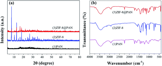
The XRD pattern, FT-IR spectrum, SEM image and energy spectrum X-ray energy spectrum (EDS) of the prepared samples were analyzed to confirm the successful preparation of ZIF-8@PAN composite beads. As shown in Fig. 1a, the diffraction peak of the synthesized ZIF-8 crystal sample corresponds to the diffraction peak reported in the literature to confirm the phase purity.51 The XRD pattern (Fig. 1a) shows that ZIF-8@PAN composite beads have almost the same characteristic peaks as ZIF-8, but the peak intensity is slightly weaker, which indicates that ZIF-8 crystals have been successfully loaded into PAN beads.54 As shown in the FT-IR spectrum (Fig. 1b), the peaks near 2921 cm−1 and 2851 cm−1 are attributed to the methylene and methyl stretching vibrations in polyacrylonitrile.55 The absorption band at about 2245 cm−1 is related to the tensile vibration of the –C![[triple bond, length as m-dash]](https://www.rsc.org/images/entities/char_e002.gif) N group in PAN.55 The mixed vibration peak of –CN appeared near 1046 cm−1.55 The absorption peaks near 3335 cm−1 and 2921 cm−1 are related to the stretching vibration of the methyl group of 2-methylimidazole and the C–H bond in the imidazole ring.29 The peak near 1580 cm−1 is the tensile vibration of the C
N group in PAN.55 The mixed vibration peak of –CN appeared near 1046 cm−1.55 The absorption peaks near 3335 cm−1 and 2921 cm−1 are related to the stretching vibration of the methyl group of 2-methylimidazole and the C–H bond in the imidazole ring.29 The peak near 1580 cm−1 is the tensile vibration of the C![[double bond, length as m-dash]](https://www.rsc.org/images/entities/char_e001.gif) N bond in the imidazole ring,29 and the peak near 421.27 cm−1 is the tensile vibration of the Zn–N bond.29 For ZIF-8@PAN, the peaks in the sample are caused by loading ZIF-8 into PAN. Combined with the FT-IR spectrum analysis of ZIF-8, PAN and ZIF-8@PAN, no new peaks appeared in ZIF-8@PAN. This shows that the process of loading ZIF-8 into PAN to prepare ZIF-8@PAN composite beads only involves physical mixing.
N bond in the imidazole ring,29 and the peak near 421.27 cm−1 is the tensile vibration of the Zn–N bond.29 For ZIF-8@PAN, the peaks in the sample are caused by loading ZIF-8 into PAN. Combined with the FT-IR spectrum analysis of ZIF-8, PAN and ZIF-8@PAN, no new peaks appeared in ZIF-8@PAN. This shows that the process of loading ZIF-8 into PAN to prepare ZIF-8@PAN composite beads only involves physical mixing.
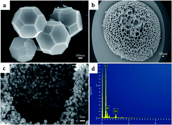
As shown in Fig. 2a, the synthesized ZIF-8 sample has a dodecahedron structure. According to Fig. 2b, the cross-section of the pure polyacrylonitrile beads reflects the internal hollow porous structure. Fig. 2c shows that the ZIF-8 crystal loaded into the PAN maintains its original form. Fig. S1a1, a2, b1, b2, c1 and c2† show the SEM images of ZIF-8, PAN and ZIF-8@PAN-2:1 at different magnifications. Analysis of the EDS of ZIF-8, PAN and ZIF-8@PAN (Fig. 2d and S2†) showed that Zn is present in the ZIF-8@PAN beads. Combined with Fig. 2, S1 and S2,† it shows that the ZIF-8 crystal has been successfully filled into the inner cavity of the pure PAN beads. In order to fully identify the microstructure of ZIF-8 and ZIF-8@PAN-2:1 samples, HRTEM images were taken through transmission electron microscope (TEM). Fig. S3 and S4† show the HRTEM images of ZIF-8 and ZIF-8@PAN-2:1 samples at different magnifications. It can be inferred that the ZIF-8 particles are wrapped around the PAN, and the ZIF-8 micron-level particles are opaque to electrons. All in all, the above characterization results (XRD, FT-IR, SEM, EDS and HRTEM) proved the successful preparation of ZIF-8@PAN composite beads, and the ZIF-8 in the composite beads retained its original crystal structure.
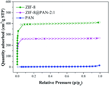
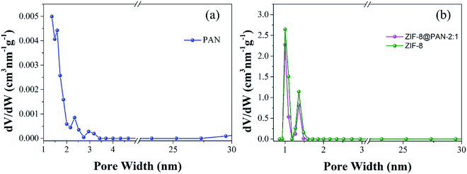
Brunauer–Emmett–Teller (BET) analysis was used to characterize the porous characteristics of ZIF-8PAN by nitrogen adsorption–desorption method at 77 K. As shown in Fig. 3, ZIF-8 crystals and ZIF-8@PAN-2:1 composite beads exhibit steep nitrogen absorption under low relative pressure (P/P0 = 0–0.01), which indicates that they have a typical type I isotherm. However, PAN beads show obvious adsorption only when the relative pressure (P/P0) is close to 1, showing a typical type III adsorption isotherm. The porosity parameters are shown in Table 2: the BET surface areas of PAN beads, ZIF-8@PAN composite beads and ZIF-8 crystals are 10.0126, 777.4763 and 1193.5031 m2 g−1, respectively. Compared with ZIF-8 crystals, due to the low loading of ZIF-8 in the polyacrylonitrile carrier, the BET surface area of ZIF-8@PAN-2:1 composite beads is reduced by about 33%. According to the single-point method, the corresponding total pore volumes of the samples were 0.018804, 0.410185, and 0.632431 cm3 g−1, respectively. As shown in the corresponding NLDFT pore size distribution curve (Fig. 4), (a) PAN pore size distribution is mainly distributed in 1–2 nm, indicating that there is mainly a microporous structure, but also a small amount of mesoporous structure; (b) ZIF-8 and ZIF-8@PAN sample, the pore size is mainly distributed in 1–2 nm, indicating that it is mainly a microporous structure.
| Materials | SBET (m2 g−1) | Vtotal (cm3 g−1) |
|---|---|---|
| PAN | 10.0126 | 0.018804 |
| ZIF-8@PAN-2:1 | 777.4763 | 0.410185 |
| ZIF-8 | 1193.5031 | 0.632431 |
3.2. ZIF-8@PAN captures iodine in vapor
As shown in Fig. 5, the maximum captured iodine of the sample beads was calculated according to the gravimetric method. The iodine absorption capacity of pure PAN beads is only 1.8 wt%. However, ZIF-8@PAN-1:4, ZIF-8@PAN-1:3, ZIF-8@PAN-1:2, ZIF-8@PAN-2:1, ZIF-8@PAN-3:1, ZIF-8@PAN-4:1 and ZIF-8 crystals have higher iodine adsorption capacity, 240, 260, 277, 266, 366, 415, 376 and 234 wt% respectively. It seems that as the loading rate of ZIF-8 in the composite beads increases, the ability to capture iodine increases, but when the iodine increases to 3![[thin space (1/6-em)]](https://www.rsc.org/images/entities/char_2009.gif) :
:![[thin space (1/6-em)]](https://www.rsc.org/images/entities/char_2009.gif) 1, the iodine absorption capacity decreases slightly. The composite bead sample formed by embedding ZIF-8 in PAN has a higher ability to capture iodine gas than pure ZIF-8 crystal, which indicates that the combination of the two has a synergistic effect. The introduction of ZIF-8 crystals into polyacrylonitrile will cause its chain sequence to change, thereby forming free cells, through which iodine can reach the surface of ZIF-8 crystals and be captured.27 The composite beads with low ZIF-8 content have less ZIF-8 content, so the iodine capture ability is low, while the content of ZIF-8 crystals is too large, and the porosity of the polyacrylonitrile beads decreases, which leads to a decrease in the ability to capture iodine.29 The XRD pattern, FT-IR spectrum, SEM image and energy spectrum X-ray energy spectrum (EDS) analysis of the composite beads after capturing gaseous iodine showed that the skeleton of the ZIF-8 crystal had collapsed. Therefore, ZIF-8@PAN composite beads can be used as a temporary storage material for capturing gaseous iodine.
1, the iodine absorption capacity decreases slightly. The composite bead sample formed by embedding ZIF-8 in PAN has a higher ability to capture iodine gas than pure ZIF-8 crystal, which indicates that the combination of the two has a synergistic effect. The introduction of ZIF-8 crystals into polyacrylonitrile will cause its chain sequence to change, thereby forming free cells, through which iodine can reach the surface of ZIF-8 crystals and be captured.27 The composite beads with low ZIF-8 content have less ZIF-8 content, so the iodine capture ability is low, while the content of ZIF-8 crystals is too large, and the porosity of the polyacrylonitrile beads decreases, which leads to a decrease in the ability to capture iodine.29 The XRD pattern, FT-IR spectrum, SEM image and energy spectrum X-ray energy spectrum (EDS) analysis of the composite beads after capturing gaseous iodine showed that the skeleton of the ZIF-8 crystal had collapsed. Therefore, ZIF-8@PAN composite beads can be used as a temporary storage material for capturing gaseous iodine.
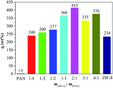 | ||
Fig. 5 Iodine vapor capture capacity of pure PAN beads, ZIF-8@PAN beads with different ZIF-8![[thin space (1/6-em)]](https://www.rsc.org/images/entities/char_2009.gif) : :![[thin space (1/6-em)]](https://www.rsc.org/images/entities/char_2009.gif) PAN mass ratios and pure ZIF-8 powder. PAN mass ratios and pure ZIF-8 powder. | ||
The XRD image of ZIF-8@PAN–I2 (Fig. 6a) shows that the characteristic peaks of the ZIF-8 crystal disappeared after iodine absorption, indicating that the crystal structure was destroyed. In the FT-IR image (Fig. 6b) of iodine captured by the composite beads, the characteristic peak near 421.27 cm−1 disappeared, indicating that the Zn–N bond was destroyed.
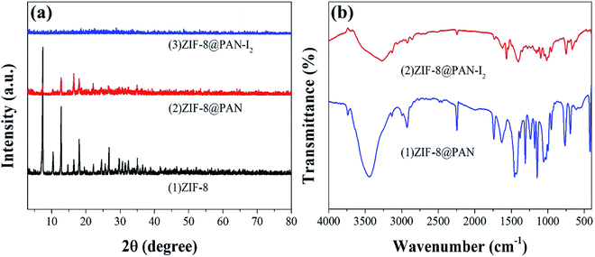 | ||
| Fig. 6 (a) XRD patterns of ZIF-8, ZIF-8@PAN and ZIF-8@PAN–I2; (b) FT-IR spectra of ZIF-8@PAN and ZIF-8@PAN–I2. | ||
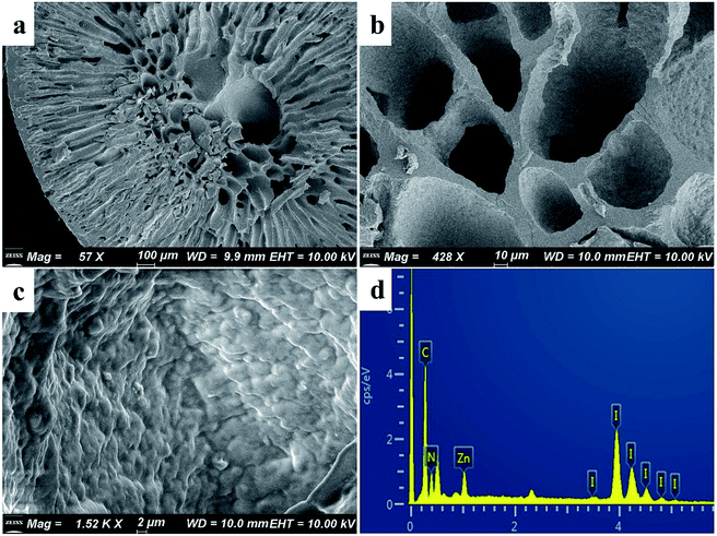
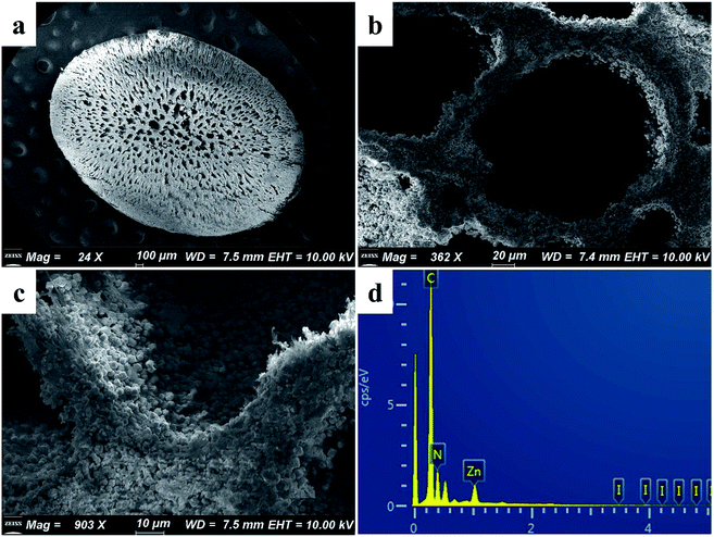
The SEM images of ZIF-8@PAN–I2 (Fig. 7a–c) show that the dodecahedral ZIF-8 crystals have disappeared, again proving that the crystal structure of ZIF-8 was destroyed after capturing excess iodine. The EDS of ZIF-8@PAN–I2 (Fig. 7d) shows that I2 was successfully captured. In summary, after the composite beads capture iodine, the frame of the ZIF-8 crystal in the beads is destroyed after the excessive I2 is captured.29 Therefore, in practical applications, ZIF-8@PAN composite beads require post-processing after capturing I2.48
3.3. The capture of iodine in organic solution by ZIF-8@PAN
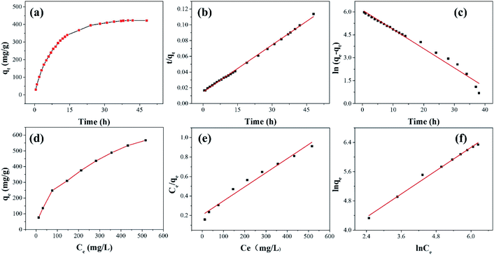
As shown in Fig. 8 and Table 3, the adsorption process of I2 by ZIF-8@PAN-2:1 is described by a pseudo-first-order model (eqn (3)) and a pseudo-second-order model (eqn (4)).
ln(qe − qt) = ln![[thin space (1/6-em)]](https://www.rsc.org/images/entities/char_2009.gif) qe − k1t qe − k1t
| (3) |
 | (4) |
| qe (mg g−1) | Pseudo-first-order kinetics | Pseudo-second-order kinetics | ||||
|---|---|---|---|---|---|---|
| 423 | k1 (1/h) | qe (mg g−1) | R2 | k2 (g mg−1 h−1) | qe (mg g−1) | R2 |
| 0.126 | 453 | 0.979 | 2.74 × 10⁻⁴ | 500 | 0.999 | |
The results show (Fig. 8b, c and Table 3) that the correlation coefficient R2 (R2 = 0.999) of the pseudo-second-order kinetic equation is relatively large, and the adsorption process of I2 on ZIF-8@PAN is best defined as a pseudo-second-order equation.
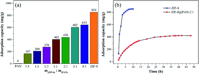
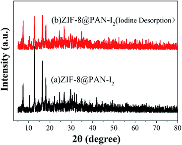
As shown in Fig. 9a, the iodine adsorption capacity of ZIF-8@PAN composite beads with different ZIF-8 content in a 500 mg L−1 I2/cyclohexane solution increased with the increase of ZIF-8 loading. The time required for ZIF-8@PAN-2:1 composite beads to reach the equilibrium of iodine adsorption is significantly longer than that of ZIF-8, and the adsorption capacity is lower. This is attributed to the fact that some ZIF-8 in the ZIF-8@PAN composite beads is embedded in the PAN, which causes the I2 to diffuse to its surface and be captured for a longer time.34 However, since the iodine adsorption capacity of ZIF-8@PAN composite beads is related to the loading of ZIF-8, the larger the load, the greater the adsorption capacity, so the adsorption capacity of composite beads is lower than that of pure ZIF-8 crystals. The ability of ZIF-8@PAN composite beads to capture iodine in I2/cyclohexane solution is significantly lower than that of gaseous iodine; due to the low loading of I2 (Fig. 5 and 9a), the ZIF-8 inside the composite beads retains the original crystal structure after capturing I2 (Fig. 10a–c). As shown in Fig. 10d, the EDS after adsorbing I2 from ZIF-8 in the solution has I element present in the composite beads, which indicates the successful capture of I2. After iodine absorption, ZIF-8@PAN composite beads can desorb iodine in ethanol, and the iodine recovery rate can reach 69%. The XRD pattern (Fig. 11) shows that ZIF-8@PAN composite beads retain the characteristic peaks of ZIF-8 after absorbing and desorbing iodine in the solution, which proves that it also maintains the original crystal structure.52
 | (5) |
ln![[thin space (1/6-em)]](https://www.rsc.org/images/entities/char_2009.gif) qe = ln qe = ln![[thin space (1/6-em)]](https://www.rsc.org/images/entities/char_2009.gif) KF + n KF + n![[thin space (1/6-em)]](https://www.rsc.org/images/entities/char_2009.gif) ln ln![[thin space (1/6-em)]](https://www.rsc.org/images/entities/char_2009.gif) Ce Ce
| (6) |
According to the isothermal parameters (Table 4) and the fitting line (Fig. 8d–f), the Freundlich model (R2 = 0.992) is more suitable than the Langmuir model (R2 = 0.972), indicating that ZIF-8@PAN-2:1 performs multilayer adsorption in this type of adsorption process.49
| qe (mg g−1) | Freundlich model | Langmuir model | ||||
|---|---|---|---|---|---|---|
| 436 | n | KF (mg g−1) | R2 | b (L mg−1) | qmax (mg g−1) | R2 |
| 0.530 | 21.78 | 0.992 | 7.06 × 10⁻³ | 690 | 0.972 | |
| Adsorbent | Iodine state | T (°C) | Eq. time | Adsorption capacity (mg g−1) | Ref. |
|---|---|---|---|---|---|
| Ag0Z | I2 (g) | 100–200 | 130–500 h | 100–170 | 14 |
| Ag@Mon-POF | I2 (g) | 70 | — | 250 | 56 |
| Ag-ETS-2 | I2 (g) | 80 | 72 h | 255 | 57 |
| Cg-5P | I2 (g) | 140 | 20 days | 870 | 58 |
| CC3 | I2 (g) | 20 | 350 h | 364 | 59 |
| SnSg | I2 (g) | 125 | 25 days | 683 | 1 |
| Al–O–F | I2 (g) | 90 | 4 h | 10–49 | 60 |
| MgAl–NO3-LDH | I2 water solution | RT | 2 h | 41.2 | 61 |
| MgO | I2 (g) | 25 | 3 h | 196 | 62 |
| KOH–AC | Cyclohexane solution of I2 | RT | 6 h | 308 | 21 |
| ZIF-8 | I2 (g) | 75 | 12 h | 1250 | 29 |
| ZIF-8@PU | Cyclohexane solution of I2 | RT | 96 h | 330 | 44 |
| HKUST-1@polymer | I2 (g) | 75 | 100 h | 348–538 | 27 |
| Cu-BTC@PES | I2 (g) | 75 | 75 h | 639 | 34 |
| ZIF-8@PAN | I2 (g) | 75 | 38 h | 643 | This work |
3.4. Iodine adsorption mechanism
Since the capture of iodine by ZIF-8@PAN composite beads as a whole includes PAN and ZIF-8, we will discuss their capture mechanisms separately. First, we will discuss the minute quantity capture of iodine on PAN. According to our previous work, there is only a small amount of physical capture of iodine in PAN.18 Through the FT-IR, XRD, EDS, and TG analysis of the ZIF-8@PAN composite beads after capturing I2, the mechanism of ZIF-8 capturing iodine was studied, which once again confirmed the previous reports on the mechanism of ZIF-8 capturing I2. Dorina F. Sava and his partners29 reported in detail the mechanism of ZIF-8 capturing iodine through experiments and molecular simulation calculations. The β cage in the ZIF-8 crystal is connected by a six-membered ring (6 MR) hole with a diameter of 3.4 Å, so the directional diffusion of iodine (3.35 Å) can be achieved, while the smaller four-membered ring (4 MR) hole is too restricted, unable to diffuse any guest molecules. The reaction sites for capturing iodine on the 2-methylimidazole linker of ZIF-8 molecular sieve are the –CH3 group and –CH2 group on the imidazole ring, through the mutual interaction of I⋯H and I⋯C effect.29,46,49 Each ZIF-8 framework can hold up to 5.4 I2 molecules. As mentioned above, ZIF-8@PAN composite microspheres capture iodine in an environment with excessive iodine vapor, showing a strong capture ability, but the load of I2 exceeds the maximum capacity of the frame, and the ZIF-8 frame will deform or even collapse. However, the amount of iodine captured by ZIF-8@PAN composite beads in I2/cyclohexane is lower than the maximum capacity of the frame, and ZIF-8 maintains a good crystal structure (shown in Fig. 10a–c). We performed thermogravimetric analysis on ZIF-8@PAN composite beads and ZIF-8@PAN composite beads after capturing iodine in I2/cyclohexane solution. As shown in Fig. 12, the TGA curve of ZIF-8@PAN–I2 and the ZIF-8@PAN precursor for comparison. From the TGA curve of ZIF-8@PAN, it can be seen that ZIF-8@PAN has high thermal stability (stable to 310 °C), indicating that it has the prospect of trapping iodine waste gas (150 °C) in practical applications. For ZIF-8@PAN–I2, the first drop of approximately 7% observed before 230 °C is due to the removal of iodine physically adsorbed by the composite beads, and the evaporation of adsorbed water and residual solvent in the composite beads. After 230 °C, due to the decomposition of ZIF-8@PAN and the release of I2, the mass of the product began to lose a lot, indicating a strong interaction between I2 and ZIF-8. It proves once again that the predecessor's conclusion that I2 captured before the ZIF-8 crystal frame is not destroyed is firmly bound in the cage.29,48 This also shows that ZIF-8@PAN composite beads can be used as a medium for capturing I2 and temporary storage.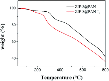 | ||
| Fig. 12 TGA plots of ZIF-8@PAN composite beads and ZIF-8@PAN composite beads after capturing iodine in solution. | ||
4. Conclusions
In summary, we report a ZIF-8@PAN composite bead with a porous structure that can be used for I2 capture in the gas and liquid phases. Through XRD, SEM, TGA and FTIR analysis, we confirmed that ZIF-8 embedded in polyacrylonitrile maintains a good crystal structure. Compared with the easily dispersible ZIF-8 powder, the millimeter-sized ZIF-8@PAN composite beads are easier to store and handle, and are more suitable for practical applications. The thermogravimetric analysis (TGA) results of ZIF-8@PAN composite beads show that it is stable below 310 °C. The ZIF-8@PAN composite beads capture iodine for a long time in an atmosphere with excessive I2 vapor, and the loading of I2 far exceeds the maximum limit of the ZIF-8 framework, causing the framework to deform or even collapse. While capturing iodine in I2/cyclohexane, due to the low I2 loading (643 mg g−1), the ZIF-8 of the composite beads maintains this good original crystal structure. Our work also provides new ideas for the application of ZIF-8@polymer and even MOF@polymer in the removal of iodine in nuclear waste treatment.Conflicts of interest
There are no conflicts to declare.Acknowledgements
This work was supported by the National Natural Science Foundation of China (21176201).References
- B. J. Riley, D. A. Pierce, J. Chun, J. Matyas, W. C. Lepry, T. G. Garn, J. D. Law and M. G. Kanatzidis, Environ. Sci. Technol., 2014, 48, 5832–5839 CrossRef CAS PubMed.
- Y. Wang, Y. Wang, L. Zhang, L. Chen, Z. Liu, X. Yin, D. Sheng, J. Diwu, J. Wang, N. Liu, Z. Chai and S. Wang, Inorg. Chem., 2017, 56, 3702–3708 CrossRef CAS PubMed.
- S. U. Nandanwar, K. Coldsnow, V. Utgikar, P. Sabharwall and D. Eric Aston, Chem. Eng. J., 2016, 306, 369–381 CrossRef CAS.
- L. Zhan, Y. Bo, T. Lin and Z. Fan, Energy Strategy Rev., 2021, 34, 100630 CrossRef.
- R. Gronnestad, G. D. Villanger, A. Polder, K. M. Kovacs, C. Lydersen, B. M. Jenssen and K. Borga, Environ. Pollut., 2018, 240, 10–16 CrossRef PubMed.
- X. Wang, L. Chen, L. Wang, Q. Fan, D. Pan, J. Li, F. Chi, Y. Xie, S. Yu, C. Xiao, F. Luo, J. Wang, X. Wang, C. Chen, W. Wu, W. Shi, S. Wang and X. Wang, Sci. China: Chem., 2019, 62, 933–967 CrossRef CAS.
- Y. Wang, Z. Liu, Y. Li, Z. Bai, W. Liu, Y. Wang, X. Xu, C. Xiao, D. Sheng, J. Diwu, J. Su, Z. Chai, T. E. Albrecht-Schmitt and S. Wang, J. Am. Chem. Soc., 2015, 137, 6144–6147 CrossRef CAS PubMed.
- P. Gu, S. Zhang, X. Li, X. Wang, T. Wen, R. Jehan, A. Alsaedi, T. Hayat and X. Wang, Environ. Pollut., 2018, 240, 493–505 CrossRef CAS PubMed.
- J. Zhang, L. Chen, X. Dai, L. Zhu, C. Xiao, L. Xu, Z. Zhang, E. V. Alekseev, Y. Wang, C. Zhang, H. Zhang, Y. Wang, J. Diwu, Z. Chai and S. Wang, Chem, 2019, 5, 977–994 CAS.
- J. Huve, A. Ryzhikov, H. Nouali, V. Lalia, G. Augé and T. J. Daou, RSC Adv., 2018, 8, 29248–29273 RSC.
- X. Hou, P. P. Povinec, L. Zhang, K. Shi, D. Biddulph, C. C. Chang, Y. Fan, R. Golser, Y. Hou, M. Jeskovsky, A. J. Jull, Q. Liu, M. Luo, P. Steier and W. Zhou, Environ. Sci. Technol., 2013, 47, 3091–3098 CrossRef CAS PubMed.
- Z. Zhang, K. Ninomiya, Y. Yamaguchi, K. Kita, H. Tsuruta, Y. Igarashi and A. Shinohara, Environ. Sci. Technol., 2018, 52, 9917–9925 CrossRef CAS PubMed.
- H. Zou, F. Yi, M. Song, X. Wang, L. Bian, W. Li, N. Pan and X. Jiang, J. Hazard. Mater., 2019, 365, 81–87 CrossRef CAS PubMed.
- Y. Nan, L. L. Tavlarides and D. W. DePaoli, AIChE J., 2017, 63, 1024–1035 CrossRef CAS.
- T. M. Nenoff, M. A. Rodriguez, N. R. Soelberg and K. W. Chapman, Microporous Mesoporous Mater., 2014, 200, 297–303 CrossRef CAS.
- A. Al-Mamoori, M. Alsalbokh, S. Lawson, A. A. Rownaghi and F. Rezaei, Chem. Eng. J., 2020, 391, 123583 CrossRef CAS.
- T. C. T. Pham, S. Docao, I. C. Hwang, M. K. Song, D. Y. Choi, D. Moon, P. Oleynikov and K. B. Yoon, Energy Environ. Sci., 2016, 9, 1050–1062 RSC.
- Q. Yu, X. Jiang, Z. Cheng, Y. Liao, Q. Pu and M. Duan, New J. Chem., 2020, 44, 16759–16768 RSC.
- B. Azambre, M. Chebbi, O. Leroy and L. Cantrel, Ind. Eng. Chem. Res., 2018, 57, 1468–1479 CrossRef CAS.
- N. Mnasri, C. Charnay, L.-C. de Ménorval, Y. Moussaoui, E. Elaloui and J. Zajac, Microporous Mesoporous Mater., 2014, 196, 305–313 CrossRef CAS.
- H. Sun, P. La, Z. Zhu, W. Liang, B. Yang and A. Li, J. Mater. Sci., 2015, 50, 7326–7332 CrossRef CAS.
- S. U. Nandanwar, K. Coldsnow, M. Green, V. Utgikar, P. Sabharwall and D. E. Aston, Chem. Eng. J., 2016, 287, 593–601 CrossRef CAS.
- C.-C. Chien, Y.-P. Huang, W.-C. Wang, J.-H. Chao and Y.-Y. Wei, Clean: Soil, Air, Water, 2011, 39, 103–108 CAS.
- G. Xu, Y. Zhu, W. Xie, S. Zhang, C. Yao and Y. Xu, Chem.–Asian J., 2019, 14, 3259–3263 CrossRef CAS PubMed.
- W. Zhang, Y. Mu, X. He, P. Chen, S. Zhao, C. Huang, Y. Wang and J. Chen, Chem. Eng. J., 2020, 379, 122365 CrossRef CAS.
- Y. Zhu, Y.-J. Ji, D.-G. Wang, Y. Zhang, H. Tang, X.-R. Jia, M. Song, G. Yu and G.-C. Kuang, J. Mater. Chem. A, 2017, 5, 6622–6629 RSC.
- B. Valizadeh, T. N. Nguyen, B. Smit and K. C. Stylianou, Adv. Funct. Mater., 2018, 28, 1870211 CrossRef.
- X. Long, Y.-S. Chen, Q. Zheng, X.-X. Xie, H. Tang, L.-P. Jiang, J.-T. Jiang and J.-H. Qiu, Sep. Purif. Technol., 2020, 238, 116488 CrossRef CAS.
- D. F. Sava, M. A. Rodriguez, K. W. Chapman, P. J. Chupas, J. A. Greathouse, P. S. Crozier and T. M. Nenoff, J. Am. Chem. Soc., 2011, 133, 12398–12401 CrossRef CAS PubMed.
- P. Chen, X. He, M. Pang, X. Dong, S. Zhao and W. Zhang, ACS Appl. Mater. Interfaces, 2020, 12, 20429–20439 CrossRef CAS PubMed.
- L. Peng, X. Zhang, Y. Sun, Y. Xing and C. Li, Environ. Res., 2020, 188, 109742 CrossRef CAS PubMed.
- B. Qi, Y. Liu, T. Zheng, Q. Gao, X. Yan, Y. Jiao and Y. Yang, J. Solid State Chem., 2018, 258, 49–55 CrossRef CAS.
- W. Xie, D. Cui, S.-R. Zhang, Y.-H. Xu and D.-L. Jiang, Mater. Horiz., 2019, 6, 1571–1595 RSC.
- Q. Zhao, L. Zhu, G. Lin, G. Chen, B. Liu, L. Zhang, T. Duan and J. Lei, ACS Appl. Mater. Interfaces, 2019, 11, 42635–42645 CrossRef CAS PubMed.
- L. Zhong, J. Ding, J. Qian and M. Hong, Coord. Chem. Rev., 2021, 434, 213804 CrossRef CAS.
- D. Chen, C. Han, Q. Sun, J. Ding, Q. Huang, T.-T. Li, Y. Hu, J. Qian and S. Huang, Green Energy Environ., 2021 DOI:10.1016/j.gee.2021.04.003.
- H. E. Emam, H. B. Ahmed, E. Gomaa, M. H. Helal and R. M. Abdelhameed, J. Photochem. Photobiol., A, 2019, 383, 111986 CrossRef CAS.
- S. L. James, Chem. Soc. Rev., 2003, 32, 276–288 RSC.
- A. U. Czaja, N. Trukhan and U. Muller, Chem. Soc. Rev., 2009, 38, 1284–1293 RSC.
- J. Xie, Y. Wang, W. Liu, X. Yin, L. Chen, Y. Zou, J. Diwu, Z. Chai, T. E. Albrecht-Schmitt, G. Liu and S. Wang, Angew. Chem., Int. Ed. Engl., 2017, 56, 7500–7504 CrossRef CAS PubMed.
- L. Wang, P. Chen, X. Dong, W. Zhang, S. Zhao, S. Xiao and Y. Ouyang, RSC Adv., 2020, 10, 44679–44687 RSC.
- Z. J. Li, Y. Ju, H. Lu, X. Wu, X. Yu, Y. Li, X. Wu, Z. H. Zhang, J. Lin, Y. Qian, M. Y. He and J. Q. Wang, Chemistry, 2021, 27, 1286–1291 CrossRef CAS PubMed.
- A. Sarkar, A. Adhikary, A. Mandal, T. Chakraborty and D. Das, Cryst. Growth Des., 2020, 20, 7833–7839 CrossRef CAS.
- E. M. Mahdi, A. K. Chaudhuri and J.-C. Tan, Mol. Syst. Des. Eng., 2016, 1, 122–131 RSC.
- Y. R. Lee, X. H. Do, K. Y. Cho, K. Jeong and K.-Y. Baek, ACS Appl. Nano Mater., 2020, 3, 9852–9861 CrossRef CAS.
- A.-N. Au-Duong and C.-K. Lee, Cryst. Growth Des., 2017, 18, 356–363 CrossRef.
- Y. Pan, Y. Liu, G. Zeng, L. Zhao and Z. Lai, Chem. Commun., 2011, 47, 2071–2073 RSC.
- J. T. Hughes, D. F. Sava, T. M. Nenoff and A. Navrotsky, J. Am. Chem. Soc., 2013, 135, 16256–16259 CrossRef CAS PubMed.
- Z. Wang, Y. He, L. Zhu, L. Zhang, B. Liu, Y. Zhang and T. Duan, Mater. Chem. Phys., 2021, 258, 123964 CrossRef CAS.
- Y. Yu, L. Ren, M. Liu, S. Huang, X. Xiao, R. Liu, L. Wang and W. Xu, ACS Appl. Mater. Interfaces, 2019, 11, 31291–31301 CrossRef CAS PubMed.
- N. L. Torad, M. Hu, Y. Kamachi, K. Takai, M. Imura, M. Naito and Y. Yamauchi, Chem. Commun., 2013, 49, 2521–2523 RSC.
- Y. Pan, D. Heryadi, F. Zhou, L. Zhao, G. Lestari, H. Su and Z. Lai, CrystEngComm, 2011, 13, 6937 RSC.
- S. Ma, S. M. Islam, Y. Shim, Q. Gu, P. Wang, H. Li, G. Sun, X. Yang and M. G. Kanatzidis, Chem. Mater., 2014, 26, 7114–7123 CrossRef CAS.
- X. Yang, Y. Zhou, Z. Sun, C. Yang and D. Tang, Colloids Surf., A, 2020, 603, 125292 CrossRef CAS.
- S. Madakbaş, E. Çakmakçı and M. V. Kahraman, Thermochim. Acta, 2013, 552, 1–4 CrossRef.
- A. P. Katsoulidis, J. He and M. G. Kanatzidis, Chem. Mater., 2012, 24, 1937–1943 CrossRef CAS.
- L. Wu, J. A. Sawada, D. B. Kuznicki, T. Kuznicki and S. M. Kuznicki, J. Radioanal. Nucl. Chem., 2014, 302, 527–532 CrossRef CAS.
- B. J. Riley, J. Chun, J. V. Ryan, J. Matyáš, X. S. Li, D. W. Matson, S. K. Sundaram, D. M. Strachan and J. D. Vienna, RSC Adv., 2011, 1, 1704–1715 RSC.
- T. Hasell, M. Schmidtmann and A. I. Cooper, J. Am. Chem. Soc., 2011, 133, 14920–14923 CrossRef CAS PubMed.
- A. Miller and Y. Wang, J. Environ. Radioact., 2014, 133, 35–39 CrossRef CAS PubMed.
- L. Kentjono, J. C. Liu, W. C. Chang and C. Irawan, Desalination, 2010, 262, 280–283 CrossRef CAS.
- S. U. Nandanwar, J. Dantas, K. Coldsnow, M. Green, V. Utgikar, P. Sabharwall and D. E. Aston, Adsorption, 2016, 22, 335–345 CrossRef CAS.
Footnote |
| † Electronic supplementary information (ESI) available. See DOI: 10.1039/d1ra05223c |
| This journal is © The Royal Society of Chemistry 2021 |

