
 Open Access Article
 This Open Access Article is licensed under a Creative Commons Attribution-Non Commercial 3.0 Unported Licence
A facile template-assisted electrodeposition approach to porous Cu/Cu2O nanowires†
Jin Zhang‡
 ab,
Jia Hao Ma‡b,
Jingyuan Bai*c,
Dalong Yanga,
Meilin Zhangc,
Zhou Yanga,
Longyi Fana,
Xiao Lin Chenab and
Ren Guo Guan*a
ab,
Jia Hao Ma‡b,
Jingyuan Bai*c,
Dalong Yanga,
Meilin Zhangc,
Zhou Yanga,
Longyi Fana,
Xiao Lin Chenab and
Ren Guo Guan*a
aEngineering Research Center of Continuous Extrusion, Ministry of Education, Dalian Jiaotong University, Dalian 116028, P. R. China. E-mail: guanrenguo@sina.com
bState Key Laboratory of Solidification Processing, Center of Advanced Lubrication and Seal Materials, Northwestern Polytechnical University, Xi'an, Shaanxi 710072, P. R. China
cSchool of Materials Science and Engineering, Northeastern University, Shenyang 110819, P. R. China. E-mail: baekkyungwon@163.com
First published on 10th September 2021
Abstract
Although nanoporous materials have been fabricated by electrodeposition using micelles of P-123 as structure-directing entities, the possible geometry obtained has been limited to nanoporous films. Herein, a novel dual-template assisted electrodeposition method to fabricate Cu/Cu2O porous nanowires (PNs) using polymeric micelles as a soft template and polycarbonate membranes as a hard template is reported. These nanowires consist of a porous skeleton with nanosized pores of 20 nm on average and crystallized ligaments. Morphology, composition, and crystal structure are systematically investigated and the formation mechanism is discussed. The as-deposited Cu/Cu2O PNs are found to exhibit high electrocatalytic activity toward electroreduction of nitrate. At an applied cathodic potential of 0.53 V vs. the reference reversible hydrogen electrode, the selectivity for NH3 conversion is 37.3%. Our approach is anticipated to work for the synthesis of PNs of other materials that could be obtained via electrochemical means.
Introduction
The fabrication of one-dimensional (1D) nanomaterials, such as nanowires, nanotubes, nanobelts, and nanorods, has sparked great interest due to their unique physicochemical properties relative to bulk.1,2 The specific confinement effects and significant surface effect have made them important building blocks of nanotechnology.3 Porous nanowires (PNs) are specific 1D nanomaterials that associate porous structure with 1D geometry. The presence of void space in nanowires can improve the materials utilization efficiency, and more importantly, their catalytic performance can be largely enhanced owing to the high surface area and short diffusion path lengths for ions and electrons. Given their great potential, several techniques have been put forward in order to create pores in nanowires, by either one-step nanofabrication4 or stepwise synthetic approaches.5 To date, most of the PNs are prepared based on the second approach, which requires firstly the construction of nanowire backbones and, subsequently etch away the intermediaries. This method combines different techniques, such as hydrothermal synthesis,6 electrodeposition,7 electrospining,8 chemical vapor deposition,9 to name a few. Electrodeposition stands out from the rest as it can be used to fabricate PNs at low cost PNs using removable nanotemplates.7 However, the desired product and the sacrificial materials need to be chemically/electrochemically very different, which often limits precise composition design and tailoring.Lately, hydrogen bubbles, a green and promising dynamic template, have been intensively studied for electrodeposition of 2D and 3D hierarchical porous nanostructures.10 In those cases, H2 bubbles are continuously generated, and coalesce freely. When bubble growth is confined inside nanopores of a hard template, i.e., dual-template assisted electrodeposition, PNs can be straightforwardly prepared. For example, Podlaha11 and coworkers successfully fabricated Fe–Ni–Co PNs into porous polycarbonate membranes at low pH by adopting nanosized hydrogen bubbles as a dynamic template. This method strongly relies upon the concentrations of protons and the bubble stabilizer to maintain sufficient, however nanosized, bubble generation. Nanotube formation presents an additional challenge to hydrogen templating within a nanoporous membrane owing to vigorous bubble aggregation in the center of a template pore.
A soft template consisting of spherical micelles of di- or triblock copolymers (e.g., polystyrene-block-poly(oxyethylene), known as KLE, or poly(ethylene glycol)-block-poly (propylene glycol)-block-poly(ethylene glycol), known as P-123) appears to be more suitable for PN dual-template assisted electrofabrication owing to simultaneous metal deposition and micelle assembly in liquid without involving any gas phase.12,13 Very recently, we demonstrated the electrodeposition of mesoporous Ni and CuNi films with tunable pore alignment and morphology from an aqueous surfactant electrolyte using P-123 as the structure-directing entity.13 P-123 also has been applied to control metal growth inside deep channels of alumina membranes.14 However, instead of forming PNs, nanotube was obtained, due to alumina exhibits outstanding adsorption ability to P-123 micelles. A P-123 micelle-phobic template should be carefully chosen to make PN deposition possible.
Dual template-assisted electrodeposition, is a very effective approach for the synthesis of PNs due to its reliability and controllability in terms of composition and properties. To date, metal oxide or composite PNs have shown appealing applications in electrochemical performance, water remediation, and energy storage.15–17 For example, metallic copper and cuprous oxide (Cu2O) bi-phase composites exhibit remarkable electrocatalytic conversion for nitrate ion reduction, because they can smartly relay electrons.18 Moreover, Cu1+ can strongly bind and preserve reaction intermediates for long time on the surface, which is a key factor in electrocatalytic reactions.19 However, the preparation of bi-phase Cu/Cu2O PNs is difficult, not only because Cu2O shows metastability and instability, but also because Cu has a strong preference for forming nanodendrites and wires instead of extended networks.20
For the aforementioned reasons, it is envisaged that the development of dual-template assisted electrodeposition to fabricate Cu/Cu2O PNs emerges as a challenging industrial issue that could trigger the development of novel green synthesis of NH3 from nitrate-contaminated water. Compared to fully dense nanocomposite materials, a porous network makes the material better suited as an electrocatalyst.
Herein, we report on the synthesis of Cu/Cu2O PNs with one-step potentiotatic electrodeposition by adopting P-123 as a soft template and commercial porous polycarbonate (PC) membrane as a hard template. The P-123 micelles confine the nucleation events, resulting in a highly porous structure. The electrochemical characteristics toward nitrate reduction are evaluated. We found that the NO3− is electroreduced with approximately 37% NH3 selectivity at −0.53 V vs. the reference reversible hydrogen electrode (RHE). The presented dual-template assisted electrodeposition process is a new way to prepare PNs using abundant materials, more efficiently and at low cost.
Experimental
Synthesis of Cu/Cu2O PNs
All chemicals were purchased from Energy Chemical Co. and used as received. Milli-Q water was used throughout the experiments. Electrochemical fabrication of Cu/Cu2O PNs was carried out in a CHI760B electrochemical workstation (CH Instruments Inc., Austin, TX) with a standard three-electrode cell system. PC membranes with 200 nm nominal pore diameter (Whatman Ltd) were used as the working electrode (WE). A thin film of Pt is sputtered onto one side of PC templates to render them conductive and the Pt layer was put in contact with a copper plate held inside a commercial holder. A circular area of 19.635 cm2 was exposed to the electrolyte for deposition. A platinum wire served as counter electrode (CE). The WE and CE were mounted parallel to each other with a distance of 2 cm. A double junction Ag/AgCl 3 M KCl electrode was used as the reference electrode (RE).The electrolyte consisted of 0.25 M Cu(Ac)2 and 37 g L−1 P-123. Prior to deposition, at least 1 h stirring time was required to assure the Cu2+ is well incorporated within the hydrophilic domain of the P-123 micelles. The deposition of Cu/Cu2O PNs was carried out potentiostatically at E = −0.3 V. N2 (99.99% purity) was bubbled through the electrolyte during electrodeposition. The electrodeposition of fully dense Cu nanowires was carried out by applying a constant potential of −0.3 V in a bath containing 0.5 M CuSO4. Fully dense Cu/Cu2O nanowires were electrodeposited from a solution containing 0.25 M Cu(Ac)2 at −0.3 V. The pH was left unprepared for the electrodeposition of Cu/Cu2O PNs (pH = 5.2). All the experiments were conducted at 25 °C. After the depositions were completed, PC residues were removed by soaking the membranes in chloroform for 24 h. The obtained black powders were centrifuged and washed with water and ethanol for several times. The products were then vacuum dried at 60 °C for 8 h.
Structural characterization
Scanning electron microscopy (SEM) images and EDX analyses were performed on a FEI Themis Z microscope operated at 5 kV and 10 kV, respectively. Transmission electron microscopy (TEM) and HRTEM analyses were performed on a FEI Themis Z microscope operated at 200 kV. X-ray diffraction (XRD) were recorded with a Bruker diffractometer in the 25–80° 2θ range using Cu Kα radiation. The ultraviolet-visible (UV-Vis) absorbance spectra were measured on a PerkinElmer LAMBDA 365 spectrophotometer. Dynamic light scattering (DLS) was performed on a Malvern Zetasizer Nano.Electroreduction of NO3−
The electroreduction of nitrate was carried out with a two-compartment cell consisting of a Pt wire as CE and an Ag∣AgCl (3 M KCl) electrode as reference electrode. The two compartments were separated with a Nafion film. The Cu/Cu2O PNs were resuspended in a mixture consisting of isopropanol and Nafion (20 vol%) to form a 5 mg mL−1 catalyst ink. 20 μL of the catalyst ink was drop-casted onto a glassy carbon electrode with a diameter of 5 mm. The PN-modified glassy carbon WE was then dried under ambient conditions. In the cathode electrode chamber, 0.1 M K2SO4 with 50 ppm KNO3 solution was used, while 0.1 M K2SO4 solution only was used in the CE chamber. Ar (99.99% purity) gas was bubbled through the cathode electrolyte before the nitrate-electroreduction test to eliminate dissolved N2 and O2. Linear sweep voltammetry (LSV) was conducted at a rate of 10 mV s−1 and potentiostatic testing was performed at −0.53 V vs. RHE for 10 h at a stirring rate of ∼300 rpm. For the sake of comparison, the electroreduction behaviors of fully dense Cu nanowires and Cu/Cu2O nanowires were also measured using the same conditions. The NO3− and the produced NO2− and NH3 were quantified based on the standard method21 using UV-Vis spectrophotometry. The UV-Vis absorption spectra and the corresponding calibration curves are shown in Fig. S1.†Calculation of the current efficiency, yield, and selectivity
The current efficiency was calculated according to the charge consumed for synthesizing the NH4+ and the total charge passed through the electrode, using eqn (1):21| Current efficiency = (8F × cNH4+ × V) /(MNH4+ × Q) | (1) |
![[thin space (1/6-em)]](https://www.rsc.org/images/entities/char_2009.gif) 485 C mol−1) and Q is the total charge passing through the electrode.
485 C mol−1) and Q is the total charge passing through the electrode.
The yield of NH3(aq) was calculated using eqn (2):21
| YieldNH3 = (cNH4+ × V) /(MNH4+ × t × m) | (2) |
The selectivity of NH3(aq) was calculated using eqn (3):21
| Selectivity = c/ΔcNO3− × 100% | (3) |
Results and discussion
The block co-polymer poly(ethylene glycol)-block-poly(propylene glycol)-block-poly(ethylene glycol) (Pluronic P-123) has shown the ability to organize metal or oxides into a variety of mesoporous forms, via the mediation of concentration, temperature, or electrostatic, covalent, and van der Waals interactions.22–24 The P-123-assisted electrodeposition has been successfully applied to the preparation of porous films and nanotubes.14,22 When using P-123 micelles to direct metal growth inside the channels of PC membrane, two factors need to be considered: (1) P-123 micelles should not be strongly adsorbed by the channel walls and (2) the micelle spheres should be smaller than the channel diameter. In this work, PC membranes with a pore size of 200 nm were selected due to their poor adsorption ability.25 The concentration of P-123 used is 37 g L−1, which is above the critical micelle concentration (CMC) but well below the threshold for lyotropic liquid structures, thus, the viscosity of the solution is low enough for the electroactive species to penetrate inside the channel and enable electrodeposition. Shown in Fig. 1 is the typical preparation process. The detailed mechanism of micelle-driven porous structure formation was explained in our previous reports.12,13 The mean size of the micelle spheres in solution is 20 nm, as measured by DLS (Fig. S2†). Once the soft template-containing solution and the hard template were ready, an external potential was applied to direct the nanosized micelles to enter the channels, eventually forming PNs.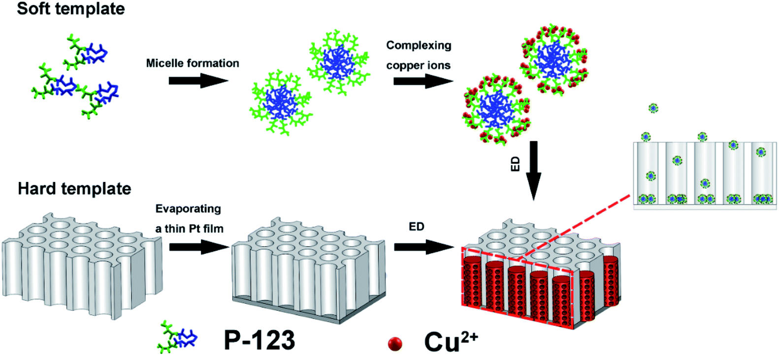 | ||
| Fig. 1 Schematic illustration of P-123 micelles assembly strategy for the preparation of Cu/Cu2O PNs. ED stands for electrodeposition. | ||
Fig. 2 depicts typical SEM images of Cu/Cu2O PNs grown by electrodeposition at a constant potential of −0.3 V for 2100 s.
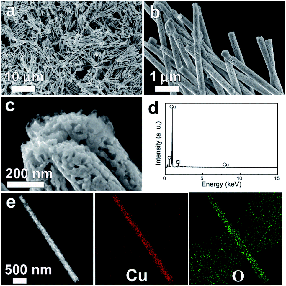 | ||
| Fig. 2 (a) low-magnification, (b) high-magnification, and (c) ultrahigh magnification SEM images of the as-prepared Cu/Cu2O PNs. (d) EDX spectrum. (e) TEM image and the corresponding Cu and O EDX mapping. | ||
The SEM micrographs clearly show that the PNs can be obtained in high yields with a length of around 9 μm and a diameter of approximately 270 nm (see also the corresponding TEM image in Fig. 2e). The diameter of the as-prepared PNs is slightly larger than the nominal pore size, because the channels inside PCs are not completely cylindrical.26 The PNs all have similar lengths, indicating that the P-123 micelle-driven growth proceeds at the same rate from the bottom of the channel to the top. This is an important feature to avoid nanotube formation. Moreover, high-magnification SEM (Fig. 2b) demonstrates that nanopores are homogeneously distributed throughout the entire nanowires. The pore sizes, shown in Fig. 2c, are found to be around 20 nm, which is consistent with the DLS result of P-123 micelle sizes. Energy-dispersive X-ray spectroscopy (EDX) (Fig. 2d) confirms that the PNs are composed of Cu and O. The silicon signal comes from the silicon substrate, onto which the PNs were drop-casted for SEM observation. TEM and the associated elemental distribution images (Fig. 2e) reveal that Cu and O are homogeneously distributed.
Although some researchers have reported that it is difficult to modify micelle size by simply increasing concentration once its CMC had been exceeded,14 the amount of P-123 in the electrolyte plays a key role in nanoporous structure formation. In our laboratory, attempts to deposit PNs from aqueous solution containing 8 g L−1 P-123 failed. Although 8 g L−1 is much lower than 37 g L−1, yet well above the CMC. Specifically, as shown in Fig. S3,† nanowires with a rough surface were obtained instead. This could be explained by the varying amount of structure-directing agent. When the micelle concentration is low, the interstices left by this soft template are rather large, leading to the formation of relative dense looking nanowires.
A typical XRD pattern of the as-deposited Cu/Cu2O PNs embedded in PC membranes is shown in Fig. 3. It can be seen that Cu and Cu2O coexist in the PNs. In the case of Cu2O, five characteristic peaks located at 29.6°, 36.4°, 42.3°, 61.4°, and 73.6° are clearly observed, which can be indexed to the (110), (111), (200), (220), and (311) crystal planes of Cu2O (pattern: JCPDS no. 05-0667).27,28 With respect to Cu, three representative peaks located at 43.3°, 50.4°, and 74.1° for the indices (111), (200), (220) can be detected, which match well with the JCPDS pattern no. 04-0836.18 It is worth noting that no impurities or extra phases are observed in the XRD pattern and metastable Cu2O survives the template removal and subsequent drying.
 | ||
| Fig. 3 XRD pattern of the Cu/Cu2O PNs. Peaks denoted Δ and □ belong to Cu and Cu2O phases, respectively. | ||
Stable Cu/Cu2O PNs were successfully deposited from a bath containing Cu(Ac)2 and P-123 at a preparation pH value of 5.2. It is already well-established that at low overpotential, Cu2O deposition is favored, while pure Cu will be obtained when deposition overpotential is high.29 Simultaneous formation of Cu and Cu2O is possible at intermediate potentials. Due to the low solubility of monovalent copper in an aqueous acidic solution, the reduction of Cu2+ into Cu+ followed by precipitation as Cu2O can occur. Therefore, the possible reactions are expressed in the following equations:30
| Cu2+ + 2e− ⇔ Cu | (4) |
| Cu2+ + e− ⇔ Cu+ | (5) |
| 2Cu+ + H2O ⇔ Cu2O + 2H+ | (6) |
Shown in Fig. S4† is the change of current density during deposition, in which three different stages are observed. For the first 500 s, negative current density increases to the maximum, which can be ascribed to the initial Cu/Cu2O formation. As deposition proceeds, the formation of semiconductor Cu2O decreases the conductivity of PNs, and thus decreased the negative current density. Analogous current density changes were previous observed in the growth of electrodeposited Cu2O thin films.31 Further experimental proof is nevertheless needed to gain deeper knowledge of the formation mechanism of Cu/Cu2O PNs.
The inner porous microstructure and crystallinity of Cu/Cu2O PNs were further investigated by TEM. Fig. 4a shows a lower magnification TEM image to capture the overall morphology. The nanowires embrace a porous region and a denser region featuring brighter contrast. This can be attributed to the pores inside PC do not have a constant cross section, so as to the nanowires that duplicate their morphology. The dense region is probably too thick for electrons to traverse. A zoomed view of the porous region taken by TEM is shown by Fig. 4b, in which the occurrence of open-cell porosity can be observed. A detailed high-resolution TEM (HRTEM) image, exhibited in Fig. 4c, revealed that the Cu/Cu2O PNs are highly crystalline and the lattice fringes are definite. The interplanar distances (0.246 nm, 0.208 nm) shown on the image can be ascribed to the (111) planes of the cubic Cu2O and (111) planes of the face-centered cubic (fcc) Cu, respectively. In addition, an empty zone, enclosed by a red dotted area, can be regarded as one pore of about 20 nm in diameter. This result is in accordance with DLS observations regarding the size of the P-123 micelle. Fig. 4d shows the corresponding selected area electron diffraction (SAED) pattern, for which the continuous rings can be attributed to the reflection planes of Cu and Cu2O. In particular, no evidence for other compounds or crystals is detected.
 | ||
| Fig. 4 (a) TEM, (b) zoomed TEM, and (c) high-resolution TEM images of the as-deposited Cu/Cu2O PNs, (d) corresponding selected area electron diffraction (SAED) pattern with the Miller indices of the diffraction rings. Diffraction rings denoted by Δ and □ belong to Cu and Cu2O phases, respectively. | ||
Copper-based materials are known to be very efficient in producing ammonia by electroreduction of nitrate.32–35 It is reported that adsorbed NO is the key reactive intermediate in the formation of NH3. Electrons transfer from Cu2O to Cu could facilitate the intermediate formation and suppress the H2 evolution reaction.36 However, the weak adsorption capability of Cu to NO will result in low NH3 conversion efficiency.37,38 Moreover, Cu2O demonstrates higher adsorption energy of nitrate and nitrito ions compared to that of Cu, indicating that more reactive species will be trapped by the electrocatalyst37,39,40 and eventually facilitate ammonia electrosynthesis. In view of the highly porous morphology, the as-deposited Cu/Cu2O PNs are expected to be suitable candidates for electrosynthesis of NH3 from nitrate. Electroreduction of NO3− was performed in an H-type cell separated by a proton-exchange membrane (see Fig. 5a). The WE was constructed by drop-casting Cu/Cu2O PNs on glassy carbon. LSV of the PN-modified glassy carbon electrode in 0.1 M K2SO4 electrolyte with and without KNO3 were performed under ambient conditions. Fig. 5b shows that in the presence of KNO3 the current density abruptly increased, indicating the availability of Cu/Cu2O for NO3− electroreduction. To identify products generated, a potentiostatic test was performed at a constant potential of −0.53 V vs. RHE, which is relatively low so as to avoid hydrogen evolution. Because the nitrate destruction rate strongly depends on the applied potential,33,35 product analysis was carried out after 10 h of reduction. Both ammonia and nitrite are detected in the solution as nitrate-electroreduction products.
 | ||
| Fig. 5 (a) Schematic illustration of the electrocatalytic cell configuration, (b) LSV of the electrode in 0.1 M K2SO4 with and without KNO3, (c) selectivity of NO3− electroreduction products at −0.53 V vs. RHE, and (d) NH3 yields with Cu and Cu/Cu2O fully dense nanowires and Cu/Cu2O PNs. | ||
The amounts of different products generated are illustrated in Fig. 5c, in which 37.3% is ammonia, 30.9% is nitrite, and the other reductive products included NO2−, NOx, N2, and N2H4.13 For comparison, potentiostatic tests for fully dense Cu nanowires and Cu/Cu2O nanowires were performed at the same conditions. Cu nanowires were electrodeposited from a bath containing copper sulfate (Fig. S5†), because attempts to produce pure Cu nanowires from copper acetate solution failed. Cu/Cu2O nanowires could be obtained from the copper acetate bath when the porous structure-directing agent P-123 is absent (Fig. S6†). Fig. 5d shows the NH3 yields of different materials, and the Cu/Cu2O PNs outperform the two fully dense counterparts. The NH3 yield, selectivity, and current efficiency for the three samples are calculated and shown in Table 1. As expected, introducing Cu2O into Cu (fully dense Cu/Cu2O nanowires) facilitates nitrate electroreduction to ammonia, in which the yields (1.53 mmol h−1 g−1), selectivity (15.4%), and current efficiency (21.2%) are greatly improved compared to Cu (NH3 yields 1.17 mmol h−1 g−1, selectivity 11.4%, current efficiency 17.5%). In addition, the highly porous structure, i.e., Cu/Cu2O PNs, further enhances the electrocatalytic performance, and the NH3 yield, selectivity, and current efficiency are 2.73 mmol h−1 g−1, 37.3%, and 35%, respectively. The eletrocatalytic performance of reported metal or composite nanocatalysts is listed in Table S1.† The as-deposited Cu/Cu2O PNs shows moderate NH3 yield and selectivity. Considering the feasibility of the synthetic route, non-noble metal-based catalyst and the relatively low applied potential, our work would open a new avenue for constructing efficient 1D porous materials for ammonia synthesis from nitrate electroreduction.The morphology and crystallinity of Cu/Cu2O PNs after the 10 h electroreduction test were analyzed by SEM and XRD. As can be seen from Fig. S7 and S8,† no obvious structural collapse or morphology worsen can be observed after the test, demonstrating the high durability of Cu/Cu2O PN electrodes for NO3− electroreduction. Note that in the SEM image (Fig. S7†) the organics attached on the surface of the PNs is Nafion.
| Sample | NH3 yields/mmol h−1 g−1 | Selectivity/% | Current efficiency/% |
|---|---|---|---|
| Cu/Cu2O PNs | 2.73 | 37.3 | 35 |
| Cu/Cu2O nanowires | 1.53 | 15.4 | 21.2 |
| Cu nanowires | 1.17 | 11.4 | 17.5 |
Conclusions
In this study, we demonstrate the preparation of Cu/Cu2O PNs based on a novel electrodeposition method within porous PC membranes where P-123 micelles are used to direct the growth of porous structure. Cu/Cu2O is deposited in the interstices left by the P-123 micelles, thus a relatively high P-123 concentration is desired to produce a highly porous structure. SEM and TEM observations revealed that nanopores are well distributed throughout the nanowires. Moreover, the Cu/Cu2O PNs show enhanced selectivity (37.3%) and current efficiency (35%) for nitrate electroreduction to ammonia over fully dense Cu or Cu/Cu2O nanowires. We found that the presence of the Cu2O phase and the porous structure are the key factors for nitrate conversion to ammonia. Our results presented here not only indicate the capability of creating nanoporous structures in 1D geometry by electrodeposition, but also present a new green synthesis process for NH3 at low cost with abundant materials.Author contributions
Conceptualization, J. Z.; methodology, J. H. M. and J. Y. B.; validation, J. Z. and J. Y. B.; formal analysis, J. H. M. and X. L. C.; investigation, L. F., Z. Y., M. Z. and J. H. M.; resources, J. Z.; data curation, J. Z.; writing—original draft preparation, J. Z. and J. H. M.; writing—review and editing, R. G. G. and J. Y. B.; visualization, J. Z.; supervision, R. G. G.; project administration, D. Y.; funding acquisition, J. Z. All authors have read and agreed to the published version of the manuscript.Conflicts of interest
There are no conflicts to declare.Acknowledgements
Financial support provided by the National Natural Science Foundation of China (51901186), China Postdoctoral Science Foundation (2018M643730), Liaoning Province “Xingliao Talent Plan” (XLYC2002070) is acknowledged.Notes and references
- C. R. Martin, Science, 1994, 266, 1961 CrossRef CAS PubMed.
- H. Q. Cao, Y. Xu, J. Hong, H. Liu, C. Yin, B. Li, C. Tie and Z. Xu, Adv. Mater., 2001, 13, 1393 CrossRef CAS.
- N. P. Dasgupta, J. Sun, C. Liu, S. Brittman, S. C. Andrews, J. Lim, H. Gao, R. Yan and P. Yang, Adv. Mater., 2014, 26, 2137 CrossRef CAS PubMed.
- X. Zhang, D. Li, L. Bourgeois, H. Wang and P. A. Webley, ChemPhysChem, 2009, 10, 436 CrossRef CAS PubMed.
- L. Liu, E. Pippel, R. Scholz and U. Gösele, Nano Lett., 2009, 9, 4352 CrossRef CAS PubMed.
- J. Jiang, J. Liu, R. Ding, X. Ji, Y. Hu, X. Li, A. Hu, F. Wu, Z. Zhu and X. Huang, J. Phys. Chem. C, 2010, 114, 929 CrossRef CAS.
- F. Li, J. He, W. L. Zhou and J. B. Wiley, J. Am. Chem. Soc., 2003, 125, 16166 CrossRef CAS PubMed.
- C. Niu, J. Meng, X. Wang, C. Han, M. Yan, K. Zhao, X. Xu, W. Ren, Y. Zhao, L. Xu, Q. Zhang, D. Zhao and L. Mai, Nat. Commun., 2015, 6, 7402 CrossRef PubMed.
- C. X. Shan, Z. Liu, Z. Z. Zhang, D. Z. Shen and S. K. Hark, J. Phys. Chem. B, 2006, 110, 11176 CrossRef CAS PubMed.
- J. Zhang, M. D. Baró, E. Pellicer and J. Sort, Nanoscale, 2014, 6, 12490 RSC.
- D. Li and E. J. Podlaha, Nano Lett., 2019, 19, 3569 CrossRef CAS PubMed.
- A. Quintana, E. I. Isarain-Chávez, E. Menéndez, R. Cuadrado, R. Robles, M. D. Baró, M. Guerrero, S. Pané, B. J. Nelson, C. M. Müller, P. Ordejón, J. Nogués, E. Pellicer and J. Sort, Adv. Funct. Mater., 2017, 27, 1701904 CrossRef.
- J. Zhang, A. Quintana, E. Menéndez, M. Coll, E. Pellicer and J. Sort, ACS Appl. Mater. Interfaces, 2018, 10, 14877 CrossRef CAS PubMed.
- F. Tao, M. Guan, Y. Jiang, J. Zhu, Z. Xu and Z. Xue, Adv. Mater., 2006, 18, 2161 CrossRef CAS.
- C. Perego and R. Millini, Chem. Soc. Rev., 2013, 42, 3956 RSC.
- B. Kong, C. Selomulya, G. Zheng and D. Zhao, Chem. Soc. Rev., 2015, 44, 7997 RSC.
- A. Vu, Y. Qian and A. Stein, Adv. Energy Mater., 2012, 2, 1056 CrossRef CAS.
- A. K. Sasmal, S. Dutta and T. A. Pal, Dalton Trans., 2016, 45, 3139 RSC.
- S. Lee, D. Kim and J. Lee, Angew. Chem., Int. Ed. Engl., 2015, 54, 14701 CrossRef CAS PubMed.
- C. Li, B. Jiang, Z. Wang, Y. Li, M. S. Hossain, J. H. Kim, T. Takei, J. Henzie, Ö. Dag, Y. Bando and Y. Yamauchi, Angew. Chem., Int. Ed. Engl., 2016, 55, 12746 CrossRef CAS PubMed.
- Y. Wang, Y. Yu, R. Jia, C. Zhang and B. Zhang, Natl. Sci. Rev., 2019, 6, 730 CrossRef CAS.
- E. Isarain-Chávez, M. D. Baró, E. Pellicer and J. Sort, Nanoscale, 2017, 9, 18081 RSC.
- S. Ohya, T. Hyodo, Y. Shimizu and M. Egashira, J. Ceram. Soc. Jpn., 2004, 112, 619 CrossRef CAS.
- Y. Y. Liu, J. G. Li, Q. F. Zhang, N. Zhou, E. Uchaker and G. Z. Cao, Electrochem. Commun., 2011, 13, 1276 CrossRef CAS.
- L. Weltje, W. D. den Hollander and H. T. Wolterbeek, Environ. Toxicol. Chem., 2003, 22, 265 CrossRef CAS PubMed.
- M. Motoyama, Y. Fukunaka, T. Sakka, Y. H. Ogata and S. Kikuchi, J. Electroanal. Chem., 2005, 584, 84 CrossRef CAS.
- W. Chen, Z. Fan and Z. Lai, J. Mater. Chem. A, 2013, 1, 13862 RSC.
- M. J. Nine, B. Munkhbayar, M. S. Rahman, H. Chung and H. Jeong, Mater. Chem. Phys., 2013, 141, 636 CrossRef CAS.
- T. D. Golden, M. G. Shumsky, Y. Zhou, R. A. VanderWerf, R. A. Van Leeuwen and J. A. Switzer, Chem. Mater., 1996, 8, 2499 CrossRef CAS.
- J. Tu, Y. Yuan, H. Jiao and S. Jiao, RSC Adv., 2014, 4, 16380 RSC.
- Y. Yang, J. Han, X. Ning, W. Cao, W. Xu and L. Guo, ACS Appl. Mater. Interfaces, 2014, 6, 22534 CrossRef CAS PubMed.
- Z. Mácová, K. Bouzek and J. Šerák, J. Appl. Electrochem., 2007, 37, 557 CrossRef.
- K. Bouzek, M. Paidar, A. Sadílková and H. Bergmann, J. Appl. Electrochem., 2001, 31, 1185 CrossRef CAS.
- R. Abdallah, F. Geneste, T. Labasque, H. Djelal, F. Fourcade, A. Amrane, S. Taha and D. Floner, J. Electroanal. Chem., 2014, 727, 148 CrossRef CAS.
- D. Reyter, D. Bélanger and L. Roué, Electrochim. Acta, 2008, 53, 5977 CrossRef CAS.
- Y. Wang, W. Zhou, R. Jia, Y. Yu and B. Zhang, Angew. Chem., Int. Ed., 2020, 59, 5350 CrossRef CAS PubMed.
- D. P. Butcher Jr and A. A. Gewirth, Nano Energy, 2016, 29, 457 CrossRef.
- G. E. Dima, A. C. A. de Vooys and M. T. M. Koper, J. Electroanal. Chem., 2003, 554–555, 15 CrossRef CAS.
- A. Balkis, J. Crawford and A. P. O'Mullane, Nanomaterials, 2018, 8, 756 CrossRef PubMed.
- E. V. Filimonov and A. I. Shcherbakov, Prot. Met., 2004, 40, 280 CrossRef CAS.
Footnotes |
| † Electronic supplementary information (ESI) available. See DOI: 10.1039/d1ra04770a |
| ‡ Both authors contributed equally to the work. |
| This journal is © The Royal Society of Chemistry 2021 |