 Open Access Article
Creative Commons Attribution 3.0 Unported Licence
Sulfated zirconium oxide-decorated magnetite KCC-1 as a durable and recyclable adsorbent for the efficient removal of asphaltene from crude oil
Farhad Bohlooli Shaafia,
Alireza Motavalizadehkakhky*b,
Rahele Zhiani *bc,
Seyed Mohammad Mahdi Nourid and
Malihesadat Hosseinyb
aDepartment of Chemical Engineering, Faculty of Sciences, Neyshabur Branch, Islamic Azad University, Neyshabur, Iran
bDepartment of Chemistry, Faculty of Sciences, Neyshabur Branch, Islamic Azad University, Neyshabur, Iran. E-mail: R_zhiani2006@yahoo.com
cNew Materials Technology and Processing Research Center, Department of Chemistry, Neyshabur Branch, Islamic Azad University, Neyshabur, Iran
dChemical Engineering Department, Hakim Sabzevari University, Sabzevar, Iran
First published on 29th July 2021
Abstract
Sulfated zirconium oxide (ZrO2/SO42−) as a highly durable acidic reagent was immobilized on magnetite KCC-1 nanoparticles (Fe3O4@SiO2/KCC-1@ZrO2/SO42− NPs), and the resulting hybrid was used as a highly efficient recyclable adsorbent for the adsorption and removal of asphaltene from crude oil. The presence of ZrO2/SO42− groups not only promotes the adsorption capacity, but also helps recycle the adsorbents without any significant efficiency loss arising from its high chemical resistance. The results showed an obvious synergistic effect between the magnetic core (Fe3O4 NPs), fibrous silica (KCC-1) and the sulfated zirconium oxide groups with high correlation for asphaltene adsorption. The effective parameters in asphaltene adsorption, including initial asphaltene concentration, catalyst concentration and temperature, were investigated. Maximum adsorption occurred in the presence of 0.7 g L−1 of the adsorbent, at a concentration of 2000 mg L−1 of asphaltene. The asphaltene adsorption by NPs follows a quasi-second order adsorption kinetics. Asphaltene adsorption kinetics were studied by Langmuir, Freundlich, and Temkin isotherms. The prominent advantage of the adsorbent is its ability to be recovered after each adsorption by acid treatment, so that no significant reduction in adsorbent adsorption activity was observed, which can be directly attributed to the presence of ZrO2/SO42− groups in the hybrid.
Introduction
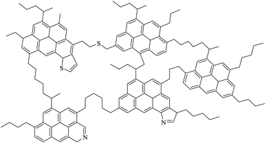
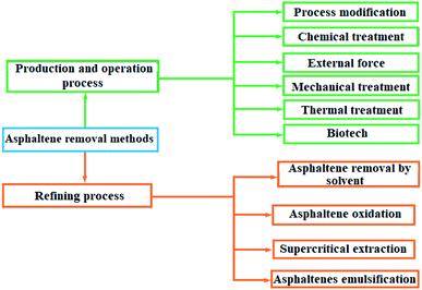
Sedimentation of heavy hydrocarbon materials includes two groups of asphaltene and wax. The closure of wells and process transmission lines, the failure of process equipment for operation, as well as a severe decline in catalyst efficiency are among the problems of sediment formation. In the face of the problem of asphaltene deposition in upstream industries, two strategies have been considered to prevent sediment formation and descaling treatment.1,2 In the process modification method, in addition to thermodynamic equilibrium conditions, fluid retention time is one of the effective factors in creating sediment. Chemical treatment, external force application, mechanical treatment, heat treatment and biotechnology method are among the methods of asphaltene removal in the production and operation processes. There are four methods to remove asphaltene from the bottom products of the vacuum distillation tower, which are solvent asphalting, asphalt oxidation, supercritical extraction and asphalt emulsion.3Asphaltene (Scheme 1) is a section of crude oil or other carbonated source. Asphaltene contains complex molecules, which dissolve in toluene or dichloromethane but are insoluble in low boiling point paraffin solvents, such as normal heptane. Asphaltenes can be derived from crude oil, coal or oil shale. They are a polycystic cluster structure that has been alternately replaced by alkyl groups, and has heteroatoms (oxygen, nitrogen, sulfur) and very small amounts of metal (such as nickel and iron).4 The molecular formula of C74H87NS2O is proposed for the structure of a medium asphaltene. However, the exact molecular formula of asphaltene is unclear and its structure varies depending on its source. Scheme 1 shows a schematic of the asphaltene structure.5,6
Various factors are effective in the formation and deposition of heavy organic materials from crude oil, which can be pointed to the characteristics and composition of the percentage of crude oil, the type of fluid injected, pressure, temperature, and the characteristics of canals (e.g., well pipes) that the reservoir fluid flows through.7 The presence of asphaltene in crude oil has many problems, so that its non-removal from crude oil causes great and irreparable damage to the petrochemical industry. Hence, a wide variety of methods have been developed to remove asphaltene. Asphaltene removal methods are schematically shown in Fig. 1.
One of the effective methods to control asphaltene deposition is the use of chemical additives, such as surfactants,3 polymeric inhibitors6 and adsorbents. So far, several adsorbents for the adsorption of asphaltene from a petroleum solution have been developed, such as β-zeolite,2 minerals (kaolin, calcite, and dolomite), clay and source rock, and various types of metal oxide nanoparticles, such as MgO, TiO2, NiO, CaO, Fe3O4, and Al2O.8 The high surface-to-volume ratio and smaller size of NPs make them easier to use in porous media, and improves the fluid flow performance in oil extraction.9,10
The amount of adsorbed asphaltene on nanoparticles strongly depends on the type of surface chemistry of the NPs, and the type of interaction force between the asphaltene and the nanoparticles. Different types of forces for asphaltene adsorption on nanoparticles mainly include asphaltene surface charge, van der Waals force and acid–base interaction between the nanoparticle surface and polar asphaltene particles.11
Previous studies have shown that these nanoparticles are good options for the adsorption and catalytic oxidation of asphaltene in the process of improving the properties of crude oil. However, the difference in the adsorption rate is due to the nature and different properties of the nanoparticles. The functional groups in asphaltene make it possible for nanoparticles to absorb electrons by sharing them with asphaltene molecules at their surface.8 Various predictions have been made for the asphaltene adsorption on nanoparticles. Several researchers have predicted the presence of oxygen and nitrogen as an important factor in the asphaltene adsorption on nanoparticles. It has been found that many factors, such as the nitrogen content, water content and H/C ratio (or aromatic rings), affect the amount of adsorption. There have been several reports of metallic nanoparticles for asphaltene removal. Franco et al.12 tested 12 different types of nanoparticles for asphaltene removal. The results showed that asphaltene adsorption has a downward trend for AlNi15, SNi15, SNi5, AlNi5, silica gel (amorphous), silica gel (crystalline), Al(II), zeolite, PdNi/Al, Al(I), and commercial silica gel. Nassar et al. showed that Ni–Pd bimetallic nanoparticles containing oxide substrates, such as SiO2, Al2O3 and TiO2, have higher adsorption capacity and catalytic activity toward asphaltene adsorption than nanoparticles that do not have oxide substrate and can be easily decomposed after adsorption.13 Magnetic metal oxides have also shown significant adsorption to asphaltene. Setoodeh et al. studied the close relationship between magnetic properties and the phenomenon of adsorption, and stated that the adsorption in paramagnetic compounds is much greater.14 The advantage of these compounds is their easy recovery after adsorption by an external magnetic field.
Due to their high specific surface area and high porosity, mesoporous materials show high surface activity, which has led to their widespread use as adsorbents, catalyst substrates and catalysts.15 The porous microstructure of these materials allows the creation of active catalytic sites on a large internal surface of porosities. This phenomenon leads to improved catalytic activity of the system. However, poor access to these active sites within the pores limits their use in cases where high mass transfer is required.16 Types of silica mesoporous materials include HMM (Hiroshima mesoporous materials), FSM (folded sheet mesoporous silica), MSU (MSU represents Michigan State University), KSW, SBA-15 (Santa Barbara Amorphous), MCM-41 (Mobil Composition of Matter) and KCC-1 (KCC represents KAUST Catalysis Centre), which have different shapes of porosities and sizes depending on the method of preparation. Among them, KCC-1 has excellent properties such as high specific surface area, morphology, fibrous surface, high mechanical stability and good thermal and hydrothermal stability, and is introduced as the best material for a catalyst substrate. KCC-1 was first invented in 2010 by Polshettiwar et al. as a new member of the mesoporous silica materials (MSMs) family in the KAUST Catalysis Centre.16 The fibrous silica KCC-1, like all members of the MSMs family, was synthesized by surfactant and silica molding, followed by mold removal. KCC-1 had a high surface area and pore volume due to the presence of fibrous silica and meso- and micro-porosities on these fibers. Polshettiwar reported that the large surface area of the material is due to the presence of dendrimeric fibrous silica and their associated channels, which in turn makes KCC-1 the first of its kind.16 It is also a good option for use in drug release, hydrogen storage and in the preparation of nanocomposites. Modification of the surface of mesoporous materials with minerals can change their properties, and improve their use for catalytic application or adsorption of certain compounds.15,16
Sulfated zirconium oxide is one of the compounds that has unique properties, such as high thermal stability, high chemical resistance, good catalytic activity and flexible modifiability, so that it has become a reliable candidate in catalytic applications. Limited reports of zirconium oxide are available for the adsorption and removal of organic/inorganic compounds. Previously, Pan et al. used a nano-hydrated zirconium oxide/polystyrene hybrid adsorbent for the removal of arsenic from water.17 Zirconium oxide-modified biochar for the adsorption of sulfate from water,18 hydrous zirconium oxide-based nanocomposite for the removal of phosphate from water,19 and zirconium sulfate-surfactant micelle mesostructure immobilized on a polymer matrix for the removal of phosphate from water20 are some of the applications of the zirconium oxide hybrids for adsorption goals. Ciesla and colleagues studied the potential of zirconium oxide as a precursor for the preparation of porous hybrids. Although its adsorption activity on a specific compound was not examined in this study, they showed that the resulting hybrid has high porosity and has high thermal stability.21 Therefore, modification of the KCC-1 surface with sulfated zirconium oxide is expected to improve its properties in order to adsorb and remove asphaltene. However, in a study on iron oxide, Nassar et al. showed that in the presence of iron oxide nanoparticles along with asphaltene, a significant reduction in the average activation energy is observed, which indicates the high catalytic activity of iron oxide. They concluded that iron oxide nanoparticles could be an excellent adsorbent or catalyst to improve the quality of heavy oil.22 In this work, magnetic Fe3O4 nanoparticles will be used to adsorb and remove asphaltene from oil. First, Fe3O4 nanoparticles were coated by silica groups, and then the KCC-1 shell is formed in situ on Fe3O4@SiO2 NPs. ZrO2/SO42− groups were then immobilized on silicate fibers in KCC-1, and the resulting Fe3O4@SiO2/KCC-1@ZrO2/SO42− nanoparticles were then used as a strong and recoverable adsorbent to remove asphaltene. The high acid stability of sulfated zirconium oxide groups in an acidic environment not only causes high adsorption stability during successive cycles, but also causes the adsorbent to maintain its adsorption activity after acid treatment.
Experimental
Materials
A sample of crude oil extracted from East Asaluyeh oil refinery, located in Asaluyeh (in Bandar Bushehr, IRAN), was investigated. Normal hexane, normal heptane and toluene with 99% purity were prepared by Merck, and used as received. Filter paper of 0.22 μm was used for asphaltene filtration. Other materials were provided from Merck and used as received. Solvents used were of analytical grade, and dried before use.Instrumentation
FT-IR spectra were obtained on a JASCO FT/IR 4600 spectrophotometer using a KBr disk. Field emission scanning electron microscopy (FE-SEM) images were taken using an FEI Quanta 200 apparatus. Energy dispersive X-ray (EDX) spectroscopy analyses were conducted on a JEOL 7600F FE-SEM instrument equipped with an energy dispersion X-ray spectrometer from Oxford Instruments. Transmission electron spectroscopy (TEM) images were taken using a Philips EM208S microscope operated at 100 kV. Magnetic behavior of the NPs was studied by vibrating sample magnetometer (VSM) method using a Lake Shore Cryotronics 7407 at room temperature. UV-Vis analyses were recorded with a SPECORD 210 PLUS Analytikjena spectrophotometer. Crystal structures of the samples were studied by X-ray diffraction (XRD) method with a Bruker D8/Advance powder X-ray diffractometer. The surface area, pore diameter, and pore volume of the samples were studied by N2 physisorption method at −196 °C with a Micromeritics ASAP 2000 instrument, surface area and pore size analyzer, using the BET (Brunauer–Emmett–Teller) method.Methods
![[thin space (1/6-em)]](https://www.rsc.org/images/entities/char_2009.gif) :
:![[thin space (1/6-em)]](https://www.rsc.org/images/entities/char_2009.gif) 3 mixing ratio of Zr
3 mixing ratio of Zr![[thin space (1/6-em)]](https://www.rsc.org/images/entities/char_2009.gif) :
:![[thin space (1/6-em)]](https://www.rsc.org/images/entities/char_2009.gif) S. The mixture was aged for 12 h at 80 °C, followed by calcination at 400 °C (10 °C) for 3 h under air atmosphere. The resulting ZrO2/SO42− was washed with deionized water three times (each by 10 mL), and then dried at 50 °C (Scheme 2).
S. The mixture was aged for 12 h at 80 °C, followed by calcination at 400 °C (10 °C) for 3 h under air atmosphere. The resulting ZrO2/SO42− was washed with deionized water three times (each by 10 mL), and then dried at 50 °C (Scheme 2).
 | ||
| Scheme 2 Preparation of sulfated-zirconium oxide from the ZrCl4 precursor.23,24 | ||
![[thin space (1/6-em)]](https://www.rsc.org/images/entities/char_2009.gif) :
:![[thin space (1/6-em)]](https://www.rsc.org/images/entities/char_2009.gif) EtOH solution (15 mL, 1
EtOH solution (15 mL, 1![[thin space (1/6-em)]](https://www.rsc.org/images/entities/char_2009.gif) :
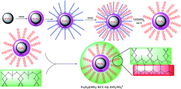
:![[thin space (1/6-em)]](https://www.rsc.org/images/entities/char_2009.gif) 3, v/v) for 15 min. Separately, ZrO2/SO42− (0.4 g) was dispersed in EtOH (10 mL), and added dropwise to the first solution that underwent sonication during a span of 10 min at room temperature. Then, 15 mL of 10% w/w NaOH was added dropwise to the solution and stirred for 24 h. The obtained Fe3O4@SiO2/KCC-1@ZrO2/SO42− was separated from the mixture by applying an external magnetic field, then isolated at room temperature after washing by deionized water and drying for 12 h at 50 °C. Scheme 3 shows a schematic view for this preparation.
3, v/v) for 15 min. Separately, ZrO2/SO42− (0.4 g) was dispersed in EtOH (10 mL), and added dropwise to the first solution that underwent sonication during a span of 10 min at room temperature. Then, 15 mL of 10% w/w NaOH was added dropwise to the solution and stirred for 24 h. The obtained Fe3O4@SiO2/KCC-1@ZrO2/SO42− was separated from the mixture by applying an external magnetic field, then isolated at room temperature after washing by deionized water and drying for 12 h at 50 °C. Scheme 3 shows a schematic view for this preparation.
In order to separate asphaltene from the filter paper, 70 mL of toluene was poured into the balloon. The third reflux was performed until the filter paper returned to its original color. The solution was poured into a weighed cylinder, and placed at room temperature to evaporate the solvent. After 24 hours, the mass of the cylinder was measured.
 | (1) |
 | (2) |
Results and discussion
Catalyst characterization
Fe3O4@KCC-1 and Fe3O4@SiO2/KCC-1@ZrO2/SO42− NPs were studied by different characterization methods. Fig. 2 shows the FTIR spectra of Fe3O4@SiO2, Fe3O4@KCC-1, ZrO2/SO42−, and Fe3O4@SiO2/KCC-1@ZrO2/SO42− NPs. Two characteristic peaks at 1100 and 800 cm−1 represent the Si–O–Si asymmetrical and symmetrical stretching vibrations, respectively, for the Fe3O4@SiO2 NPs. The presence of a characteristic peak at 560 cm−1 related to Fe–O vibrations (Str.) represents the incorporation of Fe3O4 nanoparticles within the Fe3O4@SiO2 framework.34 Fig. 2b shows the vibrations related to KCC-1 nanoparticles by two characteristic peaks at 1030, 780 cm−1, respectively, related to symmetric and asymmetric Si–O–Si vibrations, respectively, in full agreement with the literature.35 Sulfated zirconium oxide (ZrO2/SO42−) was characterized by three characteristic peaks at 1142, 1045 cm−1, and a shoulder at 994 cm−1 related to the asymmetric and symmetric modes of the S![[double bond, length as m-dash]](https://www.rsc.org/images/entities/char_e001.gif) O or S–O stretching vibrations coordinated to a metal cation.36 The series of peaks appearing at 466–748 cm−1 were attributed to the Zr–O–Zr asymmetric stretching vibrations (Fig. 2c).37 In addition, two peaks at 3420 cm−1 (broad) and 1636 cm−1 (medium) represent the stretching and bending vibrations, respectively, related to the adsorbed (or coordinated) water molecules into sulfate groups in ZrO2/SO42− in agreement with the literature (Fig. 2c).38 The immobilization of ZrO2/SO42− on Fe3O4@SiO2/KCC-1 caused the formation of a new peak at 802 cm−1 related to Zr–O–Si stretching vibration (Fig. 2d).34 In addition, all vibrations related to both ZrO2/SO42− and Fe3O4@KCC-1 could be found in the FTIR spectrum of Fe3O4@SiO2/KCC-1@ZrO2/SO42− (Fig. 2d).
O or S–O stretching vibrations coordinated to a metal cation.36 The series of peaks appearing at 466–748 cm−1 were attributed to the Zr–O–Zr asymmetric stretching vibrations (Fig. 2c).37 In addition, two peaks at 3420 cm−1 (broad) and 1636 cm−1 (medium) represent the stretching and bending vibrations, respectively, related to the adsorbed (or coordinated) water molecules into sulfate groups in ZrO2/SO42− in agreement with the literature (Fig. 2c).38 The immobilization of ZrO2/SO42− on Fe3O4@SiO2/KCC-1 caused the formation of a new peak at 802 cm−1 related to Zr–O–Si stretching vibration (Fig. 2d).34 In addition, all vibrations related to both ZrO2/SO42− and Fe3O4@KCC-1 could be found in the FTIR spectrum of Fe3O4@SiO2/KCC-1@ZrO2/SO42− (Fig. 2d).
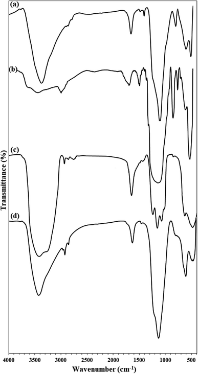 | ||
| Fig. 2 FTIR spectra of (a) Fe3O4@SiO2, (b) Fe3O4@KCC-1, (c) ZrO2/SO42−, (d) Fe3O4@SiO2/KCC-1@ZrO2/SO42−. | ||
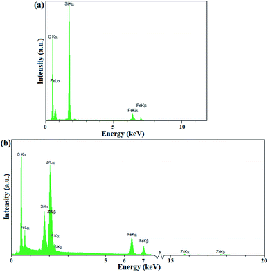
The presence of elements in Fe3O4@KCC-1 and Fe3O4@SiO2/KCC-1@ZrO2/SO42− was investigated by EDX analysis. As shown in Fig. 3a, Fe3O4@KCC-1 shows three elements of O, Fe, Si, which is in agreement with the previously reported literature.35 The EDX spectrum of Fe3O4@SiO2/KCC-1@ZrO2/SO42− also confirmed its structure by detection of all expected elements, including O, Fe, Zr, Si, and S. More importantly, the absence of any additional peaks in the EDX spectra of Fe3O4@KCC-1 and Fe3O4@SiO2/KCC-1@ZrO2/SO42− indicates the high purity of the prepared compounds.
The crystal structure of the nanoparticles was studied by X-ray diffraction analysis. The X-ray diffraction pattern of ZrO2/SO42− fully confirms its structure according to previously reported structures.27,36
As shown in Fig. 4a, the zirconium X-ray diffraction pattern has 3 characteristic peaks at 2θ = 30.5°, 50.3°, and 60.1°, which are in accordance with the ZrO2/SO42− high-crystalline tetragonal structure (JCPDS 17-0923).36,39 The crystal structure of Fe3O4 NPs is completely in line with the X-ray diffraction pattern of the cubic phase of Fe3O4 particles (Fig. 4b).40,41 Six characteristic peaks at 2θ = 30.0°, 35.5°, 43.1°, 53.7°, 57.1°, and 62.5° corresponding to the planes (indices) (220), (311), (400), (422), (511), and (440) respectively, were exactly in line with the known X-ray diffraction pattern for Fe3O4 NPs (reference JCPDS card no. 19-629).34 The coating of these nanoparticles with amorphous silicate groups reduced the crystallinity of the peaks and also caused the appearance of an amorphous peak at 2θ = 12.5°, which confirms the successful coating of the nanoparticles by silicate groups (Fig. 4c).34 The immobilization of KCC-1 groups on Fe3O4@SiO2 NPs was also confirmed by the broad amorphous peak at 2θ = 22.3° (specified in the spectrum) for the fibrous silicate in KCC-1 (Fig. 4d).42 The presence of peaks related to the crystal structure of Fe3O4 and SiO2 indicates that the crystal structure of the nanoparticles does not change during the functionalization process. Immobilization of the sulfated zirconium oxide groups on silicate fibers in KCC-1 produces characteristic peaks related to the crystal structure of ZrO2/SO42− (specified with cyclopentane markings) in the X-ray diffraction pattern of Fe3O4@SiO2/KCC-1@ZrO2/SO42−. In addition, the crystal structure of Fe3O4 is well illustrated by maintaining its characteristic peaks (with little displacement) in the X-ray diffraction pattern of the absorber with black stars. The peak corresponding to the KCC-1 groups is also shown at 2θ = 22.5° with a green star (Fig. 4e).43
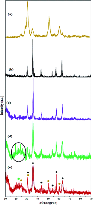 | ||
| Fig. 4 XRD patterns of (a) ZrO2/SO42−, (b) Fe3O4, (c) Fe3O4@SiO2, (d) Fe3O4@KCC-1, and (e) Fe3O4@SiO2/KCC-1@ZrO2/SO42−. | ||
The study on the magnetic properties of nanoparticles by VSM method showed that all nanoparticles have superparamagnetic properties due to the magnetic behavior of Fe3O4 nanoparticles (with coercivity equal to zero). As shown in Fig. 5, the saturation magnetization of Fe3O4, Fe3O4@SiO2, Fe3O4@KCC-1, and Fe3O4@SiO2/KCC-1@ZrO2/SO42− NPs are equal to 70, 40, 28, and 18 emu g−1, respectively. The decrease in the amount of magnetization at each stage of the functionalization of Fe3O4 indicates the successful immobilization of different groups on it (Fig. 5b–d).
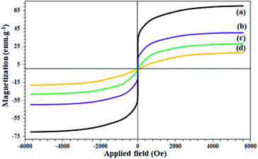 | ||
| Fig. 5 VSM curves of (a) Fe3O4, (b) Fe3O4@SiO2, (c) Fe3O4@KCC-1, and (d) Fe3O4@SiO2/KCC-1@ZrO2/SO42−. | ||
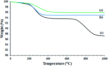
Despite the reduction of magnetization of Fe3O4-containing nanoparticles to 18 units, the nanoparticles were easily separated from the reaction mixture even after less asphaltene adsorption by applying an external magnetic field (Fig. 5d). The study on the thermal behavior of nanoparticles Fe3O4@SiO2, Fe3O4@KCC-1, and Fe3O4@SiO2/KCC-1@ZrO2/SO42− NPs showed that all of them have good stability and good correlation with other analyses, as well as their structures.
As shown in Fig. 6, Fe3O4@SiO2 NPs show only one peak at 220 °C in accordance with the 3% weight loss. This is consistent with the removal of water trapped in the nanoparticle structure, and is fully consistent with the literature (Fig. 6a).34,41,44 A slight weight loss below 220 °C was also attributed to the removal of adsorbed water (Fig. 6a).34 Fe3O4@KCC-1 nanoparticles also showed a weight loss of 5% at around 220 °C, and no further weight loss was observed up to 1000 °C (Fig. 6b). The Fe3O4@SiO2/KCC-1@ZrO2/SO42− NPs showed two weight losses at 220 °C and 750 °C, respectively, in accordance with the removal of trapped water and the removal/decomposition of sulfate groups on ZrO2/SO42−.27,36,39 The presence of a peak at 750 °C with a weight loss of about 7% confirms the successful immobilization of ZrO2/SO42− groups on Fe3O4@KCC-1 NPs. In addition, the absence of any other weight loss peaks in the TGA spectrum of Fe3O4@SiO2/KCC-1@ZrO2/SO42− indicates high purity, as well as high stability of the hybrid.
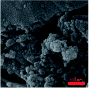
Fig. 7 shows the FE-SEM image of Fe3O4@SiO2/KCC-1@ZrO2/SO42− nanoparticles. The nanoparticles have a homogeneous morphology according to previously reported SEM images.27,36,39
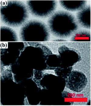
A TEM image of the Fe3O4@KCC-1 NPs showed that they have uniform fibers of silica that are growing from the center to the outside with a mean diameter of 200 nm and homogeneous morphology (Fig. 8a).
Immobilization of ZrO2/SO42− groups on silicate groups in Fe3O4@SiO2/KCC-1 caused a change in the particle morphology, according to what is shown in Fig. 8. As shown in Fig. 8, the particles have been coming out from the fibrous state of the silicate, which confirms the immobilization of the zirconium groups by the formation of Zr–O–Si bonds. The proposed structure for adsorbent NPs in Scheme 3 was also proposed in accordance with these results. The significant reduction in the crystal structure of the particles resulting from the analysis of X-ray diffraction of the adsorbent also confirms that the crystalline groups of ZrO2/SO42− are in contact with the fibrous and amorphous silicate.
Immobilization of porous sulfated zirconium oxide groups on the framework of Fe3O4@SiO2/KCC-1 and on silicate groups caused a significant increase in the porosity by 0.925 cm3 g−1 (Table 1). Significant reduction of the average porosity radius (1.992 nm) after immobilization of the sulfated zirconium oxide groups on silicate groups also reflects the successful immobilization of these groups (Table 1).
| Entry | Sample | Specific surface area (m2 g−1) | Pore volume (cm3 g−1) | Average pore radius (nm) |
|---|---|---|---|---|
| 1 | ZrO2/SO42− | 126 | 0.392 | 6.571 |
| 2 | Fe3O4 | 480 | 0.815 | 1.255 |
| 3 | Fe3O4@SiO2 | 450 | 0.786 | 1.788 |
| 4 | Fe3O4@KCC-1 | 370 | 0.520 | 6.652 |
| 5 | Fe3O4@SiO2/KCC−1@ZrO2/SO42− | 120 | 0.925 | 1.992 |
This increase in porosity along with the increased acidity of the Fe3O4@SiO2/KCC-1@ZrO2/SO42− catalyst will increase the efficiency of the catalyst to adsorb asphaltene. As will be discussed in the next section, the presence of sulfated zirconium oxide groups in the catalyst results in greater stability and maintenance of the catalytic activity of the catalyst during successive cycles, while Fe3O4@KCC-1 nanoparticles suffer a decrease in catalytic activity during successive cycles. It can be attributed to the poisoning of catalytically active sites during successive cycles. In addition, a significant reduction of the specific surface area in the final catalyst indicates a successful and significant immobilization of sulfate groups on Fe3O4@KCC-1 nanoparticles.
Asphaltene adsorption
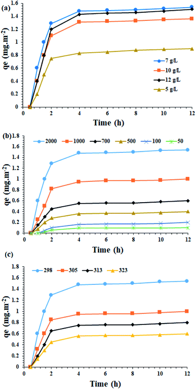
Catalyst amount. In the first step, the effect of different concentrations of Fe3O4@SiO2/KCC-1@ZrO2/SO42− on asphaltene adsorption was studied. As shown in Fig. 9a, the highest adsorption rates of 1.54 mg m−2 occurred in 0.7 g L−1 (in toluene) of the adsorbent.
Effect of the initial asphaltene concentration. In order to evaluate the effect of the initial asphaltene concentration, experiments with an initial asphaltene concentration of 50 to 2000 mg L−1 were performed over the Fe3O4@SiO2/KCC-1@ZrO2/SO42− adsorbent at a contact time of 12 h at 298 K. The results in Fig. 9b show that the initial concentration of aspartate has a significant effect on the rate of asphaltene adsorption by the absorbents. So, by increasing the initial concentration of asphaltene from 50 to 2000 mg L−1, the amount of asphaltene adsorption on both absorbents has increased. This could be due to the higher concentration gradient between the asphaltene solution and the adsorbent, which results in a stronger driving force for adsorption and consequently a higher adsorption capacity. As the initial concentration of asphaltene increases, the propulsive force of mass transfer increases, which in turn increases the amount of adsorption capacity.28 In other words, increasing the initial amount of adsorbent improves its propulsive force to penetrate or transfer this component in the thickness of the film layer, and also increases the adsorption speed.
This allows the adsorbent to reach its maximum capacity in the shortest possible time. The results obtained in this regard are in accordance with the results presented by the researchers.28,30,45 This study shows that at different temperatures, increasing the asphaltene concentration increases the adsorption on the adsorbent. Thus, after 2 h, the adsorbent is saturated and reaches its equilibrium adsorption capacity (Fig. 9b). At ambient temperature for 100 mg L−1, the experimental equilibrium adsorption qe for the adsorbent was found to be 0.2 mg m−2. When the concentration increased to 2000 mg L−1, it reaches 1.54 mg m−2. The equilibrium adsorption rate of the adsorbent has a higher adsorption rate than materials, such as titanium oxide, magnesium oxide and calcium oxide, which indicates the suitability of these NPs for use as an asphaltene adsorbent. The results clearly show the strong adsorption capacity for Fe3O4@SiO2/KCC-1@ZrO2/SO42−, which can be directly attributed to the presence of KCC-1, as well as ZrO2/SO42− groups immobilized on the Fe3O4@SiO2 framework. As will be shown in the control experiments, the strong adsorption on the Fe3O4@SiO2/KCC-1@ZrO2/SO42− NPs adsorbent could be attributed to the synergistic effect of the adsorbent groups KCC-1 and ZrO2/SO42−, as each has a significant absorption of asphaltene. In addition, the presence of ZrO2/SO42− groups in a spherical structure and on silicate fibers caused the maximal adsorption of asphaltene.
Temperature effect. In the next step, the amount of adsorbed asphaltene at the optimal concentration of 2000 mg L−1 was examined at different temperatures of 298, 305, 313 and 323 K. An optimal concentration of 0.7 g L−1 of the adsorbent was utilized. Fig. 9c shows the results of the effect of temperature on asphaltene adsorption on Fe3O4@SiO2/KCC-1@ZrO2/SO42− NPs. As shown in Fig. 9c, when the temperature drops from 298 to 323 K, the adsorption capacity of the asphaltene on the adsorbent decreases. Therefore, it can be concluded that the lower temperature facilitates the adsorption of asphaltene on the adsorbent, completely in accordance with previous published papers.28,30–32,46
Therefore, kinetic studies at 2000 mg L−1 of asphaltene at optimal value of 0.7 g L−1 of Fe3O4@SiO2/KCC-1@ZrO2/SO42 NPs adsorbent was studied. Asphaltene adsorption over Fe3O4@KCC-1 and over Fe3O4@SiO2/KCC-1@ZrO2/SO42− were studied by FTIR analysis. Asphaltene has a strong absorption related to the ![[double bond, length as m-dash]](https://www.rsc.org/images/entities/char_e001.gif) C–H and –C–H stretching vibrations at 2900–3050 cm−1. A series of peaks appearing at 1580–1610 cm−1 were assigned to C
C–H and –C–H stretching vibrations at 2900–3050 cm−1. A series of peaks appearing at 1580–1610 cm−1 were assigned to C![[double bond, length as m-dash]](https://www.rsc.org/images/entities/char_e001.gif) C bond stretching vibrations.33 In addition, a weak absorption at 1737 cm−1 was related to the C
C bond stretching vibrations.33 In addition, a weak absorption at 1737 cm−1 was related to the C![[double bond, length as m-dash]](https://www.rsc.org/images/entities/char_e001.gif) O stretching vibration in carbonyl groups. A peak at 1160 cm−1 was assigned to ester/ether bonds in the asphaltene framework (Fig. 10). Fig. 10 shows the FTIR spectra of asphaltene adsorption by Fe3O4@KCC-1, and Fe3O4@SiO2/KCC-1@ZrO2/SO42−. As shown in the figure, the presence of three characteristic peaks related to the structure of asphaltene in 2917, 2855 and 1452 cm−1 shows the physical adsorption of asphaltene on each of the nanoparticles.
O stretching vibration in carbonyl groups. A peak at 1160 cm−1 was assigned to ester/ether bonds in the asphaltene framework (Fig. 10). Fig. 10 shows the FTIR spectra of asphaltene adsorption by Fe3O4@KCC-1, and Fe3O4@SiO2/KCC-1@ZrO2/SO42−. As shown in the figure, the presence of three characteristic peaks related to the structure of asphaltene in 2917, 2855 and 1452 cm−1 shows the physical adsorption of asphaltene on each of the nanoparticles.
Adsorption isotherms
The study of the adsorption equilibrium behavior is necessary for the design and optimization of adsorption processes. In this study, the adsorption isotherm of asphaltene on Fe3O4@SiO2/KCC-1@ZrO2/SO42− adsorbent was studied using Langmuir, Freundlich, and Temkin models. Fig. 11 shows the diagrams for each of the isotherms. For this purpose, several experiments with different initial concentrations of asphaltene were performed under optimal conditions for 12 h. The parameters of all three isotherm models along with their correlation coefficients are given in Table 2. The values obtained for 1/n in the range of 5 < 1/n < 1 indicate that the adsorption is well done; if it is 1 < 1/n < 5, adsorption is relatively difficult, and if it is 1/n > 1, adsorption is very poor.33 As shown in Table 2, the values of 1/n for both adsorbents for all three models were less than 1.0, which reflects the desirability of the adsorption process.33,47 In addition, by comparing the results of the correlation coefficient (R2 values), it can be concluded that the Langmuir model has a more suitable range than the Freundlich and Temkin models, which means that the adsorption of asphaltene by both adsorbents occurs through the same mechanism as a single layer by uniform distribution of adsorption sites. This adsorption behavior for Fe3O4@SiO2/KCC-1@ZrO2/SO42− is completely consistent with the published reports of asphaltene adsorption behavior on nanoparticles. In the study of asphaltene adsorption on beta-zeolite, Kashefi et al. noticed that the Langmuir model describes the adsorption behavior of this process well.48 The results showed that the KL values for Fe3O4@SiO2/KCC-1@ZrO2/SO42− were equal to 0.0040 L mg−1, and the maximum asphaltene equilibrium adsorption (qm) was equal to 1.409 mg m−2. Metal oxide NPs, such as magnesium oxide and calcium oxide, also follow the Langmuir isotherm in asphaltene adsorption.47 However, Al and Al2O3 followed the Freundlich isotherm,28 which indicates the nature of the NPs in asphaltene adsorption.28,30,31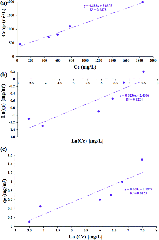 | ||
| Fig. 11 The linearized asphaltene (a) Langmuir, (b) Freundlich, (c) Temkin adsorption isotherms for Fe3O4@SiO2/KCC-1@ZrO2/SO42− NPs. | ||
According to the measurement of asphaltene adsorption by Fe3O4@SiO2/KCC-1@ZrO2/SO42− NPs, their adsorption kinetics can be predicted. To determine the kinetic mechanism of asphaltene adsorption, a duration of 12 h was chosen for this process. At times higher than 12 h, there may be some fluctuations in the adsorption process, although the best time to balance is 24 h.33,47 Data fitting with the linear form of the relationships was performed to study the adsorption kinetics of three models: (i) quasi-first-order (eqn (3)), (ii) quasi -second-order (eqn (4)), and (iii) intraparticle diffusion (eqn (5)).49 The equations for each are shown below:
Intraparticle diffusion:
| qt = k1t0.5 + 1 | (3) |
Quasi -second-order:
 | (4) |
Quasi -first-order:
| Ln(qe − qt) = Ln(qe) − k1t | (5) |
Using the slope and y-intercept of the curves, the constancy of the kinetic relations of these models was calculated and given in Table 3. The correlation coefficient (R2) of the data with the kinetic relationships for the quasi-second-order adsorption kinetics for both adsorbents is very close to 1.0. In addition, the experimental values of the equilibrium adsorption of asphaltene qe and the values obtained from the quasi-second-order adsorption kinetic relationship are very close to each other (for both adsorbents). As a result, it can be concluded that the asphaltene adsorption by Fe3O4@SiO2/KCC-1@ZrO2/SO42− NPs follows the quasi-second adsorption kinetics, and the reaction between the adsorbent surface and the asphaltene is the rate-determining step of the asphaltene adsorption process. Adaptation of the data to the quasi-second-order adsorption kinetics model can be a reason for eliminating the diffusion phase from the adsorption phenomenon, which has led to a reduction in the equilibrium time. The results are consistent with previous studies in this field that have used NPs such as alumina, nickel oxide, and titania, and have followed quasi-second-order adsorption kinetics.28,30–32,46
| Parameters | qe (mg m−2) | Kinetic models | ||||||||
|---|---|---|---|---|---|---|---|---|---|---|
| Quasi-first-order | Quasi-second-order | Intraparticle diffusion | ||||||||
| R2 | k1 (1 h−1) | qe (mg m−2) | R2 | k2 (m2 mg−1 h−1) | qe (mg m−2) | R2 | kI (mg m−2 h−0.5) | I | ||
| Value | 1.54 | 0.923 | 1.138 | 1.478 | 0.994 | 1.439 | 1.390 | 0.894 | 0.728 | 0.010 |
Control tests
In order to clarify the superiority of the Fe3O4@SiO2/KCC-1@ZrO2/SO42− adsorbent, the adsorption capability of their raw materials, including Fe3O4, Fe3O4@SiO2, ZrO2/SO42−, and KCC-1, under optimal conditions (at room temperature, in optimal amount of 0.7 g L−1 and at a concentration of 2000 mg L−1 of asphaltene) was studied during the contact time of 12 h.According to the results, Fe3O4@SiO2, ZrO2/SO42−, KCC-1, and Fe3O4@SiO2/KCC-1 showed 0.41, 0.62, 0.75, and 1.11 mg m−2 asphaltene adsorption, respectively. Fe3O4 NPs did not show any adsorption during 12 h contact time. By comparing the results with the two adsorbents, it can be concluded that the resulting hybrids with a possible synergistic effect increase the ability of ZrO2/SO42− to adsorb asphaltene. The results show that the immobilization of ZrO2/SO42− on the Fe3O4@SiO2/KCC-1 framework causes a significant increase in the adsorption capacity of asphaltene molecules.
Although ZrO2/SO42− groups have an asphaltene adsorption of 0.62 mg m−2, this significant difference with respect to the Fe3O4@SiO2/KCC-1@ZrO2/SO42− adsorbent can be directly attributed to the ZrO2/SO42− groups immobilized on the fibrous KCC-1. This, along with the spherical structure of the adsorbent nanoparticles, causes a significant increase in surface to volume ratio and consequently a maximum increase in adsorption.
Reusability
In order to show the stability and adsorption activity of the Fe3O4@SiO2/KCC-1@ZrO2/SO42− adsorbent, the adsorbent recovery was studied for 5 consecutive cycles. In order to influence the role of the ZrO2/SO42− groups, the recoverability of Fe3O4@SiO2/KCC-1 with Fe3O4@SiO2/KCC-1@ZrO2/SO42− for asphaltene adsorption was evaluated and compared in successive cycles. The adsorbent was separated from the asphaltene solution at each step by applying an external magnetic field, then washed with water and acid, and reused after heating to 150 °C. Fig. 12 shows the results of the recovery studies under optimal conditions (at room temperature, in an optimal amount of 7 g L−1 and at a concentration of 2000 mg L−1 of asphaltene) for a contact time of 12 h. A similar value of 0.7 g L−1 was used to evaluate the adsorption of Fe3O4@SiO2/KCC-1.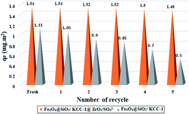 | ||
| Fig. 12 Recyclability of Fe3O4@SiO2/KCC-1@ZrO2/SO42− and Fe3O4@SiO2/KCC-1 over the asphaltene adsorption. | ||
Results were reported based on qe (in mg m−2). As shown in Fig. 12, Fe3O4@SiO2/KCC-1@ZrO2/SO42− has a higher resistance to adsorption properties than Fe3O4@SiO2/KCC-1. Subsequently, negligible activity drops were observed during successive cycles of asphaltene adsorption/desorption. As shown in Fig. 12, the value of Qe shifts from 1.54 to 1.48 mg m−2 for Fe3O4@SiO2/KCC-1@ZrO2/SO42− NPs after 5 consecutive adsorptions/desorption of asphaltene. Meanwhile, this change for Fe3O4@SiO2/KCC-1 increases from 1.11 to 0.5 mg m−2 during successive cycles, which is very significant compared to Fe3O4@SiO2/KCC-1@ZrO2/SO42−.
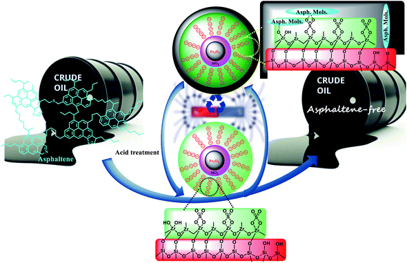
Due to the acidic and thermal treatment of the adsorbents after each asphaltene adsorption, the results reflect the high stability of the adsorbents while maintaining their adsorption properties. The presence of sulfated zirconium oxide groups not only causes stronger and better adsorption of asphaltene on the adsorbent surface, but the adsorption activity is also maintained during successive cycles. Fe3O4@KCC-1 NPs appeared to be poisoned during successive cycles, so that even with acid treatment, the catalyst activity was not restored. The high acid stability of sulfated zirconium oxide groups in an acidic environment not only causes high adsorption stability during successive cycles, but also causes the adsorbent to maintain its adsorption activity after acid treatment.
This difference can be directly attributed to the presence of KCC-1 and ZrO2/SO42− groups in the Fe3O4@SiO2/KCC-1@ZrO2/SO42− adsorbent. Due to its nature, it not only causes stronger and better adsorption of asphaltene on its surface, but the adsorption activity of the adsorbent is also maintained in successive cycles.
In another useful study, BET analysis was performed over the recovered adsorbent before and after acid treatment in successive cycles. As shown in Table 4, the specific surface area of the adsorbent decreased sharply after asphaltene exposure. The remarkable point was the successful recovery of adsorbents after acid treatment in such a way that the specific surface area returns to its original value. This reflects the stability and high activity of the adsorbent, which has maintained its surface properties. According to the results of BET (Table 4), it can be concluded that on average, about 35% of the surface of nanoparticles in each cycle is occupied by asphaltene groups. This amount also reflects the full activation of the surface after each recovery and treatment.
| Cycle | Treatment | Adsorbent |
|---|---|---|
| Specific surface area (m2 g−1) | ||
| Fresh | — | 120 |
| 1st | Before treatment | 74 |
| After treatment | 118 | |
| 2nd | Before treatment | 78 |
| After treatment | 122 | |
| 3rd | Before treatment | 78 |
| After treatment | 116 | |
| 4th | Before treatment | 75 |
| After treatment | 118 | |
| 5th | Before treatment | 78 |
| After treatment | 114 |
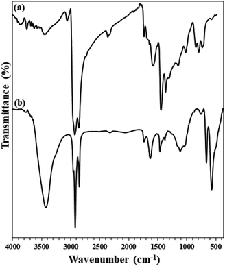
In addition, FTIR analysis of both recovered adsorbents (after heat and acid treatment) clearly confirms their high stability. As shown in Fig. 13, the FTIR spectra of the adsorbents recovered after the fifth cycle are quite similar to those of the freshly prepared ones. No change in their structure was achieved, despite acidic and thermal treatments.
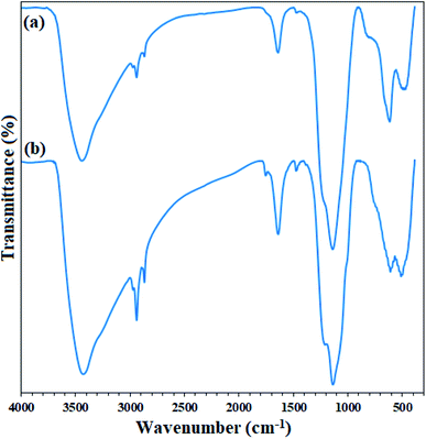 | ||
| Fig. 13 FTIR spectra of (a) freshly prepared Fe3O4@SiO2/KCC-1@ZrO2/SO42− and (b) its recovered spectrum after the 5th recycling over the asphaltene adsorption (after treatment). | ||
Conclusion
In conclusion, a highly efficient, highly durable, and recyclable adsorbent has been developed for the efficient adsorption/removal of asphaltene from crude oil by immobilization of sulfated zirconium oxide (ZrO2/SO42−) on Fe3O4@SiO2/KCC-1 NPs (Fe3O4@SiO2/KCC-1@ZrO2/SO42− NPs). The physical and structural properties of the adsorbent was studied by FTIR, XRD, VSM, BET, FE-SEM, and TEM analyses. The maximum adsorption occurred at ambient temperature in the presence of 0.7 g L−1 of the adsorbent at a concentration of 2000 mg L−1 of asphaltene. The asphaltene adsorption by the NPs follows a quasi-second order adsorption kinetics, which indicates that the adsorption process is dependent on the asphaltene concentration. Upon isotherm studies over both nanoparticles, the Langmuir model is more efficient than the Freundlich and Temkin models, which means that the adsorption of asphaltene by nanoparticles has a monolayer nature with a uniform distribution of adsorption sites. Another advantage of NPs was their ability to be recovered and reused after acid and heat treatment as an asphaltene adsorbent for several consecutive runs without significant reduction in activity. Due to the acid and heat treatment of both adsorbents after each adsorption of asphaltene, the results reflect the high stability of the adsorbents while maintaining their adsorption properties. Comparative results from control experiments showed that the immobilization of KCC-1 and ZrO2/SO42− nanoparticles on the Fe3O4@SiO2 structure significantly increased its adsorption activity towards asphaltene, which was better than Fe3O4@SiO2/KCC-1 and ZrO2/SO42−. Fe3O4@SiO2/KCC-1@ZrO2/SO42− hybrid, with the simultaneous presence of active and adsorbent groups KCC-1 and ZrO2/SO42−, creates a synergistic effect for the physical adsorption of asphaltene. The results of the control experiments showed that each of the compounds KCC-1 and ZrO2/SO42− alone can adsorb asphaltene, but have a significant difference when they are together in the catalyst hybrid. In general, the results show that Fe3O4@SiO2/KCC-1@ZrO2/SO42− nanoparticles have the ability to adsorb asphalt under mild conditions, and can be used for this purpose in the relevant industries.Conflicts of interest
The authors declare that they have no conflict of interest.Acknowledgements
This work was supported by the Research Council of Islamic Azad University, Neyshabur Branch.References
- N. N. Nassar, A. Hassan and P. Pereira-Almao, Energy Fuels, 2011, 25, 3961–3965 CrossRef CAS.
- J. J. Adams, Energy Fuels, 2014, 28, 2831–2856 CrossRef CAS.
- S. Wang, Q. Liu, X. Tan, C. Xu and M. R. Gray, Colloids Surf., A, 2016, 504, 280–286 CrossRef CAS.
- M. F. González, C. S. Stull, F. López-Linares and P. Pereira-Almao, Energy Fuels, 2007, 21, 234–241 CrossRef.
- T. F. Yen and G. V. Chilingarian, Asphaltenes and asphalts, 2: Part B, Elsevier, 2000, pp. 29–54 Search PubMed.
- M. O. González, B. I. Kharisov, T. S. Quezada, O. V. Kharissova, L. G. Hernández and I. G. de la Fuente, J. Dispersion Sci. Technol., 2019, 40, 1121–1128 CrossRef.
- G. Raj, E. Larkin, A. Lesimple, P. Commins, J. Whelan and P. Naumov, Energy Fuels, 2019, 33, 2030–2036 CrossRef CAS.
- M. S. Mazloom, A. Hemmati-Sarapardeh, M. M. Husein, H. S. Behbahani and S. Zendehboudi, Fuel, 2020, 279, 117763 CrossRef.
- J. Castillo, V. Vargas, V. Piscitelli, L. Ordoñez and H. Rojas, J. Pet. Sci. Eng., 2017, 151, 248–253 CrossRef CAS.
- S. A. Hosseini, R. Hagjoo and M. Baninaam, Pet. Sci. Technol., 2019, 37, 2330–2337 CrossRef CAS.
- M. A. Nasseri, M. Kazemnejadi, B. Mahmoudi, F. Assadzadeh, S. A. Alavi and A. Allahresani, J. Nanopart. Res., 2019, 21, 214 CrossRef.
- C. A. Franco, T. Montoya, N. N. Nassar, P. Pereira-Almao and F. B. Cortés, Energy Fuels, 2013, 27, 7336–7347 CrossRef CAS.
- N. N. Nassar, T. Montoya, C. A. Franco, F. B. Cortés and P. Pereira-Almao, Energy Fuels, 2015, 29, 4210–4221 CrossRef CAS.
- N. Setoodeh, P. Darvishi and A. Lashanizadegan, J. Dispersion Sci. Technol., 2018, 39, 452–459 CrossRef CAS.
- V. Vargas, J. Castillo, R. Ocampo-Torres, C. P. Lienemann and B. Bouyssiere, Pet. Sci. Technol., 2018, 36, 618–624 CrossRef CAS.
- V. Polshettiwar, D. Cha, X. Zhang and J. M. Basset, Angew. Chem., Int. Ed., 2010, 49, 9652–9656 CrossRef CAS PubMed.
- B. Pan, Z. Li, Y. Zhang, J. Xu, L. Chen, H. Dong and W. Zhang, Chem. Eng. J., 2014, 248, 290–296 CrossRef CAS.
- H. Ao, W. Cao, Y. Hong, J. Wu and L. Wei, Sci. Total Environ., 2020, 708, 135092 CrossRef CAS PubMed.
- L. Chen, X. Zhao, B. Pan, W. Zhang, M. Hua, L. Lv and W. Zhang, J. Hazard. Mater., 2015, 284, 35–42 CrossRef CAS PubMed.
- N. Pitakteeratham, A. Hafuka, H. Satoh and Y. Watanabe, Water Res., 2013, 47, 3583–3590 CrossRef CAS PubMed.
- U. Ciesla, M. Fröba, G. Stucky and F. Schüth, Chem. Mater., 1999, 11, 227–234 CrossRef CAS.
- N. N. Nassar, A. Hassan, L. Carbognani, F. Lopez-Linares and P. Pereira-Almao, Energy Fuels, 2012, 95, 257–262 CrossRef CAS.
- M. Kazemnejadi, M. A. Nasseri, S. Sheikh, Z. Rezazadeh and S. A. A. Gol, RSC Adv., 2021, 11, 15989–16003 RSC.
- M. A. Nasseri, S. A. Alavi, M. Kazemnejadi and A. Allahresani, ChemistrySelect, 2019, 4, 8493–8499 CrossRef CAS.
- S. Azizi, J. Soleymani and M. Hasanzadeh, Appl. Organomet. Chem., 2020, 34, e5440 CAS.
- S. Azizi and N. Shadjou, Heliyon, 2021, 7, e05915 CrossRef PubMed.
- M. A. Nasseri, M. Kazemnejadi, A. Allahresani and M. HussainZadeh, New J. Chem., 2021, 45, 7741–7757 RSC.
- N. N. Nassar, Energy Fuels, 2010, 24, 4116–4122 CrossRef CAS.
- IP 143/84, Asphaltene Precipitation with Normal Heptane, Standard Methods for Analysis and Testing of Petroleum and Related Products, Institute of Petroleum, London, 1988, vol. 1 Search PubMed.
- C. Franco, E. Patiño, P. Benjumea, M. A. Ruiz and F. B. Cortés, Fuel, 2013, 105, 408–414 CrossRef CAS.
- A. W. Marczewski and M. Szymula, Colloids Surf., A, 2002, 208, 259–266 CrossRef CAS.
- H. Alboudwarej, D. Pole, W. Y. Svrcek and H. W. Yarranton, Ind. Eng. Chem. Res., 2005, 44, 5585–5592 CrossRef CAS.
- S. Panahi, A. R. Sardarian, F. Esmaeilzadeh and D. Mowla, Mater. Res. Express, 2018, 5, 095022 CrossRef.
- B. Mahmoudi, A. Rostami, M. Kazemnejadi and B. A. Hamah-Ameen, Green Chem., 2020, 22, 6600–6613 RSC.
- R. Karimi, B. Bayati, N. C. Aghdam, M. Ejtemaee and A. A. Babaluo, Powder Technol., 2012, 229, 229–236 CrossRef CAS.
- M. A. Nasseri, S. A. Alavi, M. Kazemnejadi and A. Allahresani, RSC Adv., 2019, 9, 20749–20759 RSC.
- F. Heshmatpour and R. B. Aghakhanpour, Adv. Powder Technol., 2012, 23, 80–87 CrossRef CAS.
- D. Sarkar, D. Mohapatra, S. Ray, S. Bhattacharyya, S. Adak and N. Mitra, Ceram. Int., 2007, 33, 1275–1282 CrossRef CAS.
- J. Rodriguez, D. B. Culver and M. P. Conley, J. Am. Chem. Soc., 2019, 141, 1484–1488 CrossRef CAS PubMed.
- M. A. Nasseri, Z. Rezazadeh, M. Kazemnejadi and A. Allahresani, J. Am. Chem. Soc., 2019, 16, 2693–2705 CAS.
- M. Kazemnejadi, B. Mahmoudi, Z. Sharafi, M. A. Nasseri, A. Allahresani and M. Esmaeilpour, Appl. Organomet. Chem., 2020, 34, e5273 CAS.
- S. M. Sadeghzadeh, Appl. Organomet. Chem., 2016, 30, 835–842 CrossRef CAS.
- S. Azizi, N. Shadjou and J. Soleymani, Appl. Organomet. Chem., 2021, 35, e6031 CrossRef CAS.
- M. A. Nasseri, Z. Rezazadeh, M. Kazemnejadi and A. Allahresani, Catal. Lett., 2021, 151, 1049–1067 CrossRef CAS.
- M. Debost, P. B. Klar, N. Barrier, E. B. Clatworthy, J. Grand, F. Laine, P. Brázda, L. Palatinus, N. Nesterenko, P. Boullay and S. Mintova, Angew. Chem., Int. Ed., 2020, 59, 23491–23495 CrossRef CAS.
- G. J. DiLeo, M. E. Neff and P. E. Savage, Energy Fuels, 2007, 21, 2340–2345 CrossRef CAS.
- M. Madhi, A. Bemani, A. Daryasafar and M. R. Khosravi Nikou, Pet. Sci. Technol., 2017, 35, 242–248 CrossRef CAS.
- S. Kashefi, M. N. Lotfollahi and A. Shahrabadi, Oil Gas Sci. Technol., 2018, 73, 2 CrossRef.
- N. N. Nassar, A. Hassan and P. Pereira-Almao, Energy Fuels, 2011, 25, 1017–1023 CrossRef CAS.
| This journal is © The Royal Society of Chemistry 2021 |

