
 Open Access Article
 This Open Access Article is licensed under a Creative Commons Attribution-Non Commercial 3.0 Unported Licence
Nickel hydroxide as a non-noble metal co-catalyst decorated on Cd0.5Zn0.5S solid solution for enhanced hydrogen evolution
Dan Chen *,
Yao Xu,
Yingying Zhang,
Wenyu Sheng and
Guangren Qian
*,
Yao Xu,
Yingying Zhang,
Wenyu Sheng and
Guangren Qian
School of Environmental and Chemical Engineering, Shanghai University, No. 99 Shangda Road, Shanghai 200444, China. E-mail: dchen@shu.edu.cn
First published on 8th June 2021
Abstract
The study of non-noble metal photocatalysts provides practical significance for hydrogen evolution applications. Herein, new Cd0.5Zn0.5S/Ni(OH)2 catalysts were fabricated through simple hydrothermal and precipitation methods. The photocatalytic performance of the Cd0.5Zn0.5S/Ni(OH)2 composites under visible light was significantly improved, which was attributed to the wider visible light absorption range and less recombination of electron–hole pairs. The composite with a Ni(OH)2 content of 10% showed the best hydrogen evolution rate of 46.6 mmol g−1 h−1, which was almost 9 times higher than that of pristine Cd0.5Zn0.5S. The severe photo-corrosion of Cd0.5Zn0.5S was greatly improved, and the Cd0.5Zn0.5S/Ni(OH)2 composite exhibited a very high hydrogen evolution rate after three repeated tests. The excellent photocatalytic performance was due to the non-noble metal Ni(OH)2 co-catalyst. The excited electrons were transferred to the co-catalyst, which reduced electron–hole recombination. Moreover, the co-catalyst offered more sites for photocatalytic reactions. This study researched the mechanism of a co-catalyst composite, providing new possibilities for non-noble metal photocatalysts.
1. Introduction
Energy shortages and environmental pollution have become serious problems plaguing the development of various countries; thus, the search for green energy has aroused widespread concern.1–4 Hydrogen energy is characterized by low environmental pollution and high energy density,5–7 and is expected to become a substitute for fossil fuels.8–12 Since the Honda–Fujishima effect was discovered in 1972,13 water splitting photocatalytic technology has been considered the most potent method for obtaining hydrogen energy.14 However, the bandgap of TiO2 is relatively wide (3.2 eV), and TiO2 can only respond to ultraviolet light, which occupies 3% to 5% of solar energy.15,16 Low light availability blocks the further application of photocatalysis. Thus, many new photocatalysts with promising visible light responses have been researched and reported.17–20In the past few years, sulfide has drawn wide attention due to its low price and strong visible light absorption.21,22 Cd0.5Zn0.5S solid solution, a catalyst coupling CdS and ZnS, has a suitable bandgap width and band edge position, and has seen extensively investigated in the field of photocatalysis.23,24 However, the fast carrier recombination and severe photo-corrosion of this material have a great adverse influence on photocatalytic activity.25,26 To date, researchers have tried a variety of methods to address these problems. Xue et al. constructed 2D mesoporous ultrathin Cd0.5Zn0.5S nanosheets, and the hydrogen evolution rate was 2.2 times higher than that of Cd0.5Zn0.5S nanoparticles.27 Zhang et al. reported a NiSe2/Cd0.5Zn0.5S type-II heterojunction whose photocatalytic hydrogen evolution rate was approximately 2.1 times that of pristine Cd0.5Zn0.5S.28 Other works, such as those investigating Co2P/Cd0.5Zn0.5S,29 ZIF-8/Cd0.5Zn0.5S,30 Bi2S3/Cd0.5Zn0.5S,31 and g-C3N4/Cd0.5Zn0.5S,32 showed the feasibility of facilitating photogenerated electron migration. However, work on co-catalyst-modified Cd0.5Zn0.5S is relatively lacking.
Currently, nickel hydroxide co-catalyst is widely studied because of its low price, easy synthesis and layered structure.33–35 Many studies have shown that nickel hydroxide co-catalyst can enhance responsiveness to visible light, and promote the separation of photo-generated electron–hole pairs. Cao et al. used an electrostatic method to decorate negatively charged 3D g-C3N4 with positively charged 2D Ni(OH)2 nanosheets, and the synthesized composite released approximately 76 times more hydrogen than pristine g-C3N4.36 Liu et al. constructed a new 2D/2D layer-like Ni(OH)2/Bi4Ti3O12 composite with fast separation of electron–hole pairs due to the interfacial interaction and coupling interfaces.37 In addition, some studies have revealed that nickel hydroxide co-catalyst can provide reductive active sites. For example, Liu et al. prepared Ni(OH)2 with a three-dimensional nano-flower structure, and the special structure inhibited interlamellar superposition, and provided more active sites.38 Furthermore, Li et al. reported that doped Ni2+ exhibited a doping energy level, which accelerated the separation of photogenerated electrons, improving the full-spectrum activation.39 In short, it can be expected that nickel hydroxide co-catalyst loaded on Cd0.5Zn0.5S will have excellent photocatalytic performance.
In this study, Cd0.5Zn0.5S solid solution was synthesized by a simple hydrothermal method. Our work explored a new combination of Ni(OH)2 and Cd0.5Zn0.5S in which Ni(OH)2 was decorated as a co-catalyst on Cd0.5Zn0.5S by a chemical deposition method. Cd0.5Zn0.5S/Ni(OH)2 composites with different Ni(OH)2 contents of 5%, 10%, 15%, and 20% were prepared to explore the impact of diverse co-catalyst contents on hydrogen evolution activity. In this system, the modification of Ni(OH)2 greatly improved the photoactivity of pristine Cd0.5Zn0.5S, and the electron–hole pairs were effectively separated. The composite was characterized through ultraviolet-visible diffuse reflectance spectroscopy (UV-vis DRS), photoluminescence (PL) spectroscopy, X-ray photoelectron spectroscopy (XPS), etc., and a possible photocatalytic mechanism was proposed. This research is expected to provide new ideas for non-noble metal photocatalysts, reducing the cost of photocatalysts, which is meaningful to the practical application of photocatalytic hydrogen evolution.
2. Experimental sections
All analytical reagents were obtained from Sinopharm Chemical Reagent Co., Ltd.2.1 Preparation of Cd0.5Zn0.5S
First, 5 mmol Cd(AC)2·2H2O and 5 mmol Zn(AC)2·2H2O were mixed with 20 ml deionized water. Second, 10 ml of Na2S·9H2O (1.250 g) aqueous solution was added dropwise to the beaker under magnetic stirring. Third, the above-synthesized yellow suspension was transferred to a polytetrafluoroethylene reactor for hydrothermal reaction at a temperature of 200 °C for 12 h. Fourth, the precipitate was centrifuged, washed a few times with deionized water and absolute ethanol and then dried at 60 °C for 12 h. The prepared Cd0.5Zn0.5S catalyst was named CZS.2.2 Preparation of CZS/Ni
A total of 0.400 g CZS was added to 50 ml 0.25 M NaOH solution and subjected to ultrasonic dispersion for 0.5 h. A total of 3.3 ml, 6.6 ml, 9.9 ml, or 13.2 ml of 0.05 M Ni(NO3)2 aqueous solution was added dropwise under continuous stirring. Then, the mixture was stirred at ambient temperature for 2 h. After that, the product was washed several times with deionized water and ethanol. Then, the precipitate was dried at 60 °C for 12 h, and named CZS/Ni-5, CZS/Ni-10, CZS/Ni-15, or CZS/Ni-20, respectively.2.3 Characterizations
X-ray diffraction (XRD, Rigaku Ultimate IV) was carried out to analyse the crystallinity of the materials. The morphology and surface structure were determined by scanning electron microscopy (SEM, SU8010, Hitachi Japan). The microstructure was analysed by transmission electron microscopy (TEM, JEM-2100F). The surface composition and chemical state were recorded on a ThermoFisher ESCALAB 250Xi X-ray photoelectron spectroscopy (XPS) instrument equipped with a monochromatic Al Ka X-ray source (hv = 1486.6 eV). UV-vis absorption spectroscopy was performed on a UV-vis spectrophotometer (UV-2600, Shimadzu, Japan). The Brunauer–Emmett–Teller (BET) surface area and pore size distribution were tested with an Autosorb-IQ2 automatic specific surface area and pore size distribution analyser (Quantachrome, America). PL analysis was performed using a Gangdong Technology F-320 PL spectrophotometer.2.4 Photocatalytic experiments
The photoactivity of the above-fabricated materials was examined by an online photocatalytic reaction system (CEL-SPH2N, Beijing), with a 300 W Xe lamp (CEL-SPH2N, Beijing) under visible light illumination (λ ≥ 420 nm). A cooled circulating water system was adopted to keep the reaction at approximately 6 °C. In general, 25 mg and 50 ml of aqueous solutions containing 10 ml lactic acid and 40 ml deionized water were mixed. Before visible light irradiation, the air in the system was evacuated to keep the reaction system under a vacuum state throughout the reaction. A gas chromatograph (GC-7920, China, N2 as carrier) was employed to analyse the evolution of hydrogen every 0.5 h.2.5 Photoelectrochemical measurements
The photoelectrochemical experiment was carried out by using an electrochemical workstation (CHI 760E, Shanghai Chenhua Co., Ltd.). To mimic a traditional electrochemical system, the photocatalyst was applied to the surface of the working electrode. Pt foil was used as the counter electrode, and a saturated calomel electrode (SCE) was used as the reference electrode. During all tests, the experimental effective area was 0.8 × 1 (cm). The preparation process for the working electrode was as follows. First, 10 mg of photocatalyst was mixed with 1 ml deionized water. Then, after adding 50 μl Nafion to the mixture, the sample was sonicated for 30 min to achieve uniform mixing. Finally, 30 μl of the obtained suspension was added dropwise to an indium tin oxide (ITO) glass plate and dried at room temperature. Photocurrent response characterization was conducted by using a 300 W Xe lamp as the light source (λ > 420 nm). The bias voltage and the illumination time interval were 0 V and 20 s, respectively. The frequency range of electrochemical impedance spectroscopy (EIS) was 0.1–100 kHz.3. Results and discussion
3.1 Structural analysis
The crystallinity and phase purity of the samples were determined by XRD, as shown in Fig. 1. The XRD pattern of CZS was not a simple superposition of the patterns of CdS and ZnS (JCPDS PDF#05-0566). Compared with the pattern of pristine CdS (JCPDS PDF#06-0314), the XRD peaks of the synthesized composites shifted to higher values, which may be due to the different ionic radii of Cd2+ (0.97 Å) and Zn2+ (0.74 Å). Hence, the synthesized CZS showed a special solid solution structure, which was consistent with other works.40–42 The pristine CZS and CZS/Ni composites showed the same XRD patterns, revealing that modified the Ni(OH)2 co-catalyst did not destroy the original structure of CZS. The pristine CZS and CZS/Ni composites showed characteristic peaks at 2θ = 25.7°, 27.3°, 29.0°, 45.3°, 49.3° and 53.7°, which were consistent with the (100), (002), (101), (110), (103) and (112) planes, respectively. However, the XRD patterns of the CZS/Ni composites did not exhibit the diffraction peaks of Ni(OH)2 because of the low content of co-catalyst. The existence of Ni(OH)2 in the CZS/Ni composites needed to be further confirmed.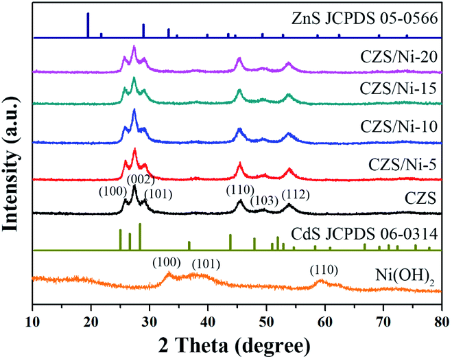 | ||
| Fig. 1 XRD patterns of pristine CZS and CZS/Ni composites. | ||
The microscopic morphology of the CZS/Ni-10 composite was observed by SEM, and Fig. 2 shows the results. From Fig. 2a and b, the synthesized composite resembled irregular nanoparticles with a size of approximately 10–50 nm. This result revealed that CZS and Ni(OH)2 were both nanostructure ed. The compositional distribution of the composite was analysed by EDS mapping. The results showed that Cd (Fig. 2d), Zn (Fig. 2e), and S (Fig. 2f) were evenly distributed. In addition, Ni (Fig. 2g) was uniformly dispersed, with a content less than that of CZS, indicating the successful doping of Ni(OH)2. According to Fig. 2c, the content ratio of Cd2+ and Zn2+ in the CZS/Ni-10 composite was 0.99![[thin space (1/6-em)]](https://www.rsc.org/images/entities/char_2009.gif) :1, which was close to the theoretical ratio of 1:1, further proving that the synthesized CZS was Cd0.5Zn0.5S. The results indicated that the Ni(OH)2 co-catalyst had been modified on CZS and the CZS/Ni-10 composite was successfully synthesized.
:1, which was close to the theoretical ratio of 1:1, further proving that the synthesized CZS was Cd0.5Zn0.5S. The results indicated that the Ni(OH)2 co-catalyst had been modified on CZS and the CZS/Ni-10 composite was successfully synthesized.
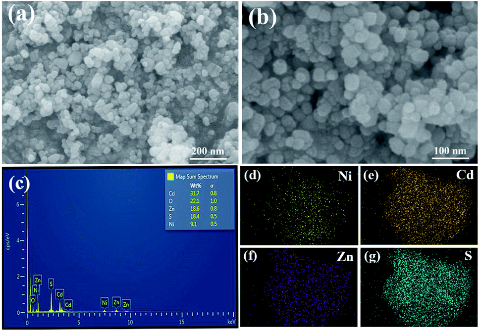 | ||
| Fig. 2 (a and b) SEM images at different magnifications of the CZS/Ni composites and the corresponding element mapping for (d) Cd, (e) Zn, (f) S and (g) Ni. | ||
The synthesis of the composite was further verified by TEM. From Fig. 3a, the Ni(OH)2 co-catalyst was anchored uniformly on the CZS. Exploring the crystal plane (Fig. 3b), we observed lattice fringes at 0.32 nm and 0.26 nm, according to the XRD results and Bragg equation, which were consistent with the (002) plane of CZS and (100) plane of Ni(OH)2, respectively, matching well with the SEM mapping results. These results indicated the successful loading of Ni(OH)2, which further proved the synthesis of the CZS/Ni-10 composite.
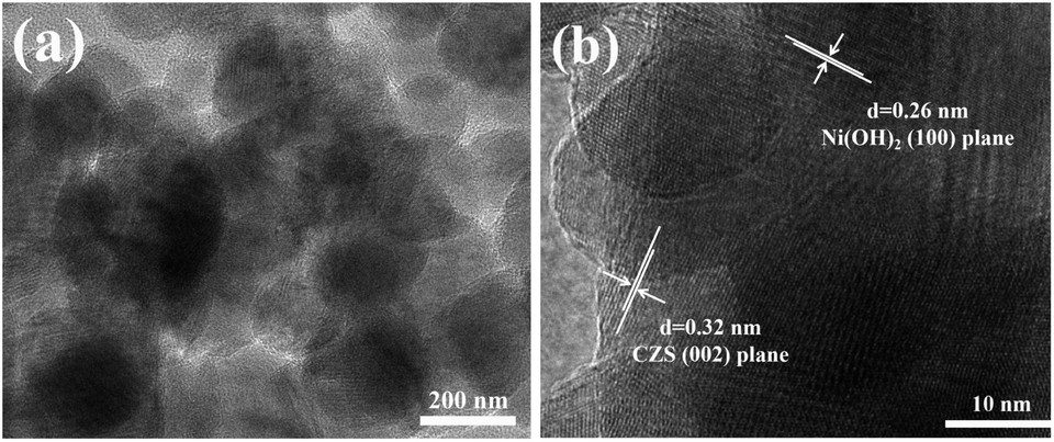 | ||
| Fig. 3 (a) TEM, and (b) HRTEM images of CZS/Ni-10 composite. | ||
The elemental composition and chemical state of the CZS/Ni-10 composite were further analysed by XPS. The Cd 3d spectrum of the composite in Fig. 4b shows peaks at 411.65 and 404.9 eV, matching well with the peaks of Cd 3d3/2 and Cd 3d5/2, respectively, indicating the typical binding energy of Cd2+.31 Similar to the Cd 3d spectrum, the Zn 2p spectrum (Fig. 4c) of the composite with peaks at Zn 2p1/2 and Zn 2p3/2 showed the oxidation state of Zn2+. The S 2p spectrum of the composite (Fig. 4d) can be separated into two different peaks at 162.62 and 161.44 eV, which correspond well to S 2p1/2 and S 2p3/2. The binding energy difference between the two peaks was limited to 1.2 eV, and the area restriction p(1/2)/p(3/2) = 1:2, indicating the presence of S2-in the composite. In Fig. 4e, the binding energies at 873.49 and 855.75 eV correspond to the characteristic peaks of Ni 2p1/2 and Ni 2p3/2, respectively, with satellite peaks of 879.50 and 861.48 eV, which conform to the standard peaks of nickel hydroxide.43–45 The results proved the coexistence of CZS and Ni(OH)2 in the CZS/Ni-10 composite, further indicating the successful synthesis of the composite.
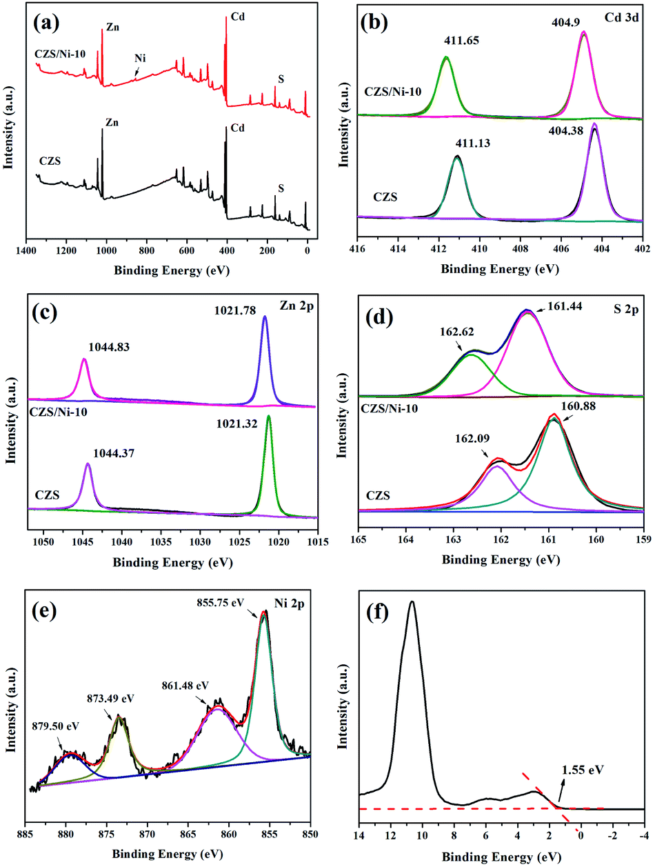 | ||
| Fig. 4 The XPS spectra of (a) CZS/Ni-10 composite, (b) Cd 3d, (c) Zn 2p, (d) S 2p, (e) Ni 2p, and (f) valence-band. | ||
Notably, the binding energies of pristine CZS and the CZS/Ni-10 composite were based on the same calibration of C 1s peak, which was 284.6 eV. Compared with the properties of the pristine CZS, the Cd, Zn, and S in the composite maintained the same state, and the binding energies slightly shifted to higher values (approximately 0.4 eV), indicating that more electrons transferred to the Ni(OH)2 co-catalyst through interface interactions.46,47 The results showed that photogenerated electrons can transfer to the co-catalyst during the photocatalytic process, promoting the separation of hole–electron pairs. In addition, Fig. 4f shows that the valence band (VB) potential of CZS was located at 1.55 eV.
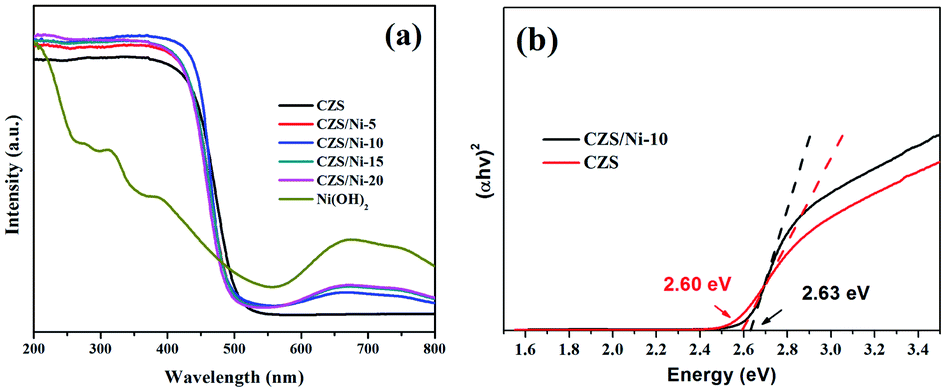
Fig. 5a shows the UV-Vis DRS spectra of the pristine CZS and CZS/Ni composites. As observed in Fig. 5a, Ni(OH)2 showed light absorptions covering the full spectrum due to the transitions of Ni2+ in oxygen octahedral sites,37,48 and CZS showed an absorption edge of 525 nm. Compared with the results for pristine CZS, the CZS/Ni composites exhibited similar absorption band edges. As shown in Fig. 5b, according to the Kubelka–Munk equation, the band gaps of pristine CZS and the CZS/Ni-10 composite were 2.60 eV and 2.63 eV, respectively. The band gap changed was may be due to band bending at the junction of two semiconductors. In addition, the composites showed additional absorption in the range of 550–800 nm, which corresponded to the absorption of Ni(OH)2. It can be inferred that Ni(OH)2 was successfully incorporated and the co-catalyst did not destroy the morphology of the original material. Thus, the CZS/Ni composites had a wider visible light absorption range than CZS, which provided more charge carriers for photocatalytic activity, improving hydrogen evolution.
 | ||
| Fig. 5 (a) UV-Vis DRS spectra of pristine CZS and CZS/Ni composites (b) the estimated band gaps of exfoliated pristine CZS and CZS/Ni-10 composites. | ||
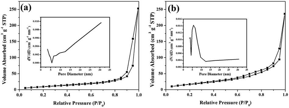
The nitrogen adsorption and desorption isotherms as well as the corresponding pore size distributions of the pristine CZS and CZS/Ni-10 samples are shown in Fig. 6. These absorption–desorption isotherms were classified as type IV,49 with obvious hysteresis loops at a relative pressure of 0.9–1.0. The shapes of the hysteresis loops are consistent with type H3, indicating the mesoporous structure of the samples. Compared with the results for pristine CZS (Fig. 6a), the hysteresis loop of the CZS/Ni-10 (Fig. 6b) composite was narrower, which could imply that the co-catalyst influenced the pore structure. The pore size distributions (inset) showed pore sizes ranging from 3 to 31 nm, which further proved the existence of mesopores. The presence of mesopores favored multilight scattering/reflection, resulting in enhanced harvesting of the exciting light and thus improved photocatalytic activity.50,51
 | ||
| Fig. 6 Nitrogen adsorption–desorption isotherms and corresponding pore size distributions (inset) of (a) pristine CZS and (b) CZS/Ni-10 composite. | ||
Table 1 demonstrates the BET surface areas, pore volume and pore sizes of the pristine CZS and CZS/Ni-10 composite. The BET surface area of the CZS/Ni-10 composite (68.1 m2 g−1) was larger than that of pristine CZS (44.1 m2 g−1), indicating an increased reaction area and therefore providing more active sites.52 Thus, the photocatalytic performance was improved. Moreover, the average pore size of CZS/Ni-10 was significantly reduced, which may be due to some co-catalyst filling the CZS pores.
| Samples | SBET (m2 g−1) | Pore volume (cm3 g−1) | Pore size (nm) |
|---|---|---|---|
| Pristine CZS | 44.1 | 0.25 | 30.7 |
| CZS/Ni-10 | 68.1 | 0.19 | 5.6 |
3.2 Photocatalytic H2 evolution performance
The photocatalytic hydrogen evolution performance of the above-synthesized materials was assessed under visible light illumination (λ ≥ 420 nm), with lactic acid (20%) as the sacrificial reagent. As observed in Fig. 7a, after 3 h of continuous irradiation, the photo-reactivity of pristine CZS was the poorest, producing only 16.6 mmol hydrogen. At a Ni(OH)2 loading content of 5%, the increase in hydrogen evolution was not obvious. The composite with a loading content of 10% had the best hydrogen evolution performance, reaching 46.57 mmol g−1 h−1, which was approximately 8.4 times higher than that of pristine CZS (Fig. 7b). However, with further increases in Ni(OH)2 loading, the photocatalytic activity of the composite decreased dramatically, which might be due to excess co-catalyst covering the active sites of CZS.53 The above results demonstrated that loading Ni(OH)2 co-catalyst can greatly enhance the photocatalytic activity. The reason may be that the migration and separation rates of charge carriers were improved. It should be noted that the photocatalytic hydrogen evolution rate in this work is substantially higher than other reported works,54–57 as shown in Table 2.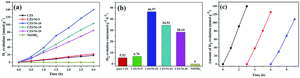 | ||
| Fig. 7 (a) Photocatalytic H2 evolution in 3 h, (b) H2 evolution rate of pristine CZS and CZS/Ni composites, (c) cycling test of photocatalytic H2 evolution of CZS/Ni-10 composite. | ||
| Photocatalyst | Light source | Solution | Activity (mmol h−1 g−1) | Ref. |
|---|---|---|---|---|
| Co0.85Se (1.5 wt%)/Cd0.5Zn0.5S | 300 W Xe lamp (λ ≥ 420 nm) | 0.2 M Na2S and 0.2 M Na2SO3 | 30.37 | 54 |
| 20%-NiTiO3/Cd0.5Zn0.5S | 300 W Xe lamp (λ ≥ 420 nm) | 0.55 M Na2S and 0.15 M Na2SO3 | 26.45 | 55 |
| Cd0.5Zn0.5S/HNTs-3 wt% | 300 W Xe lamp (λ > 400 nm) | 0.1 M Na2S and 0.1 M Na2SO3 | 25.67 | 56 |
| 13 wt% Fe2P/Cd0.5Zn0.5S | 300 W Xe lamp | 20 vol% lactic acid | 24.84 | 57 |
A three-cycle hydrogen evolution experiment was carried out to verify the reusability of the CZS/Ni-10 composite, and Fig. 7c shows the results. After three cycles, the photocatalytic evolution of the composite was decreased (125 mmol g−1 to 108.4 mmol g−1) but was still 6.5 times that of pristine CZS, indicating excellent reusability. Compared with the results of other works on sulfides,58,59 the stability of the composite was significantly increased, avoiding severe photo-corrosion. The decreased hydrogen evolution can be ascribed to the co-catalyst falling off the support; the same phenomena have been observed in similar composites.60,61 Subsequent measures can be taken to prevent the co-catalyst from falling off to maintain high photocatalytic activity.
3.3 Charge transfer studies
PL spectroscopy was performed to study the recombination process of photogenerated electron–hole pairs, and Fig. 8 shows the results. The PL intensity of the CZS/Ni composites was lower than that of pristine CZS, which contributed to the interfacial interaction of CZS and Ni(OH)2, promoting the transfer of electrons to the co-catalyst. The results demonstrated that the photogenerated electron–hole pairs of the CZS/Ni-10 composite had the lowest recombination rate, which was consistent with the effect of photocatalytic evolution.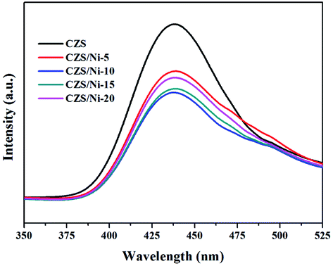 | ||
| Fig. 8 PL spectra of pristine CZS and CZS/Ni composite. | ||
The recombination of charge carriers was identified by transient photocurrent responses (I–t curves). Fig. 9a clearly shows that the photocurrent density of the CZS/Ni-10 composite was higher than that of pristine CZS. It can be inferred that the modification of the co-catalyst enhanced the absorption of visible light, promoting the generation of electrons. Some Ni2+ ions dissociated from Ni(OH)2,62 effectively facilitating the transfer efficiency of photogenerated electrons. In addition, the current density of pristine CZS decreased, indicating severe photo-corrosion. Instead, the CZS/Ni-10 composite retained a stable density, showing excellent resistance to photo-corrosion. EIS Nyquist plots (Fig. 9b) revealed that the arc radius of the CZS/Ni-10 composite was smaller than that of pristine CZS, indicating the higher electron donor density and excellent electrical conductivity of the former,63 which were beneficial to the transfer of electrons. The photoelectrochemical results coincided with the hydrogen evolution results, which indicated that Ni(OH)2 can accelerate the transfer of electrons and reduce the recombination of electron–hole pairs, thereby improving the photocatalytic activity.
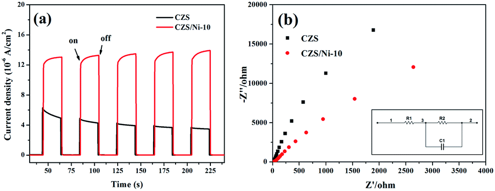 | ||
| Fig. 9 (a) The transient photocurrent responses (I–t curves) and (b) EIS Nyquist plots of pristine CZS and CZS/Ni-10 composite (inset shows the equivalent circuit). | ||
3.4 Photocatalytic mechanism
The mechanism of the CZS/Ni-10 composite was proposed as follows. First, the VB potential of CZS was identified at 1.55 eV according to the XPS spectrum. From the formula Eg = EVB − ECB, the CB potential of CZS was −1.05 eV. According to the previous analysis, the CZS/Ni-10 composite had a wider visible light absorption range and larger surface area, which were beneficial to the generation of photogenerated charge. As seen from Fig. 10, when excited by visible light, electrons transfer to the conduction band (CB). Because the positive potential of Ni2+/Ni0 (−0.23 V vs. NHE, pH = 0) is less negative than that of CZS,64 photogenerated electrons were transferred to Ni(OH)2 and reduced some Ni2+ to Ni0 atoms, finally forming Ni atoms or clusters. These Ni atoms or clusters further promoted the transfer of electrons to Ni(OH)2, and H+ was reduced to produce hydrogen.65 Lactic acid was ionized in the solution, and the positively charged holes on VB were trapped by the negatively charged lactate, which inhibited the oxidation of S2− to S0. The stability and reusability of the CZS/Ni-10 composite significantly increased, avoiding severe photo-corrosion. In short, the modification of CZS with Ni(OH)2 altered the pathway of electrons, which realized the effective separation of photogenerated electron–hole pairs, improving the effect of photocatalytic hydrogen evolution.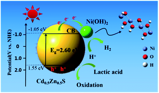 | ||
| Fig. 10 Proposed mechanism of CZS/Ni-10 composite for photocatalytic H2 evolution under visible light irradiation. | ||
4. Conclusions
In this study, a series of new CZS/Ni composites were synthesized through simple hydrothermal and precipitation methods. The results showed that Ni(OH)2 as a co-catalyst can effectively facilitate the migration of photogenerated h+ and e−, provide more reaction sites, and increase the absorption of visible light without changing the original structure of the CZS solid solution. CZS/Ni-10 had the best photocatalytic hydrogen evolution performance (46.6 mmol g−1 h−1), which was 8.4 times that of pristine CZS. In addition, the new composite had excellent recyclability and still showed excellent photocatalytic performance after three cycles. The composite had a good photocatalytic hydrogen evolution effect with low cost, which offers far-reaching significance for the study of non-noble metal photocatalysts.Author contributions
Dan Chen contributed to the conception of the study; Yao Xu performed the experiment and the data analyses and wrote the manuscript; Guangren Qian contributed significantly to analysis and manuscript preparation; Yingying Zhang, Wenyu Sheng helped perform the analysis with constructive discussions.Conflicts of interest
There are no conflicts to declare.Acknowledgements
This research work was supported by the National Nature Science Foundation of China (No. 51274138), the Program for Innovative Research Teams in University (No. IRT13078) and the Innovation Program of Shanghai Municipal Education Commission (14YZ014).Notes and references
- H. Che, C. Liu, G. Che, G. Liao, H. Dong, C. Li, N. Song and C. Li, Nano Energy, 2020, 67, 104273 CrossRef CAS
.
- L. Lu, S. Zou and B. Fang, ACS Catal., 2021, 11, 6020–6058 CrossRef CAS
- J. Liu, G. Chen and J. Sun, ACS Appl. Nano Mater., 2020, 3, 11017–11024 CrossRef CAS
- S. Yu, S. Song, R. Li and B. Fang, Nanoscale, 2020, 12, 19536–19556 RSC
- Y. Liu, S. Shen, Z. Li, D. Ma, G. Xu and B. Fang, Mater. Charact., 2021, 174, 111031 CrossRef CAS
- S. Z. Baykara, Int. J. Hydrogen Energy, 2018, 43, 10605–10614 CrossRef CAS
- B. Fang, M. Kim, J. H. Kim and J.-S. Yu, Langmuir, 2008, 24, 12068–12072 CrossRef CAS PubMed
- C. Li, H. Wu, Y. Du, S. Xi, H. Dong, S. Wang and Y. Wang, ACS Sustainable Chem. Eng., 2020, 8, 12934–12943 CrossRef CAS
- B. Fang, J. H. Kim, M.-S. Kim and J.-S. Yu, Acc. Chem. Res., 2013, 46, 1397–1406 CrossRef CAS PubMed
- D. Zhang, W. Cao, B. Mao, Y. Liu, F. Li, W. Dong, T. Jiang, Y.-C. Yong and W. Shi, Ind. Eng. Chem. Res., 2020, 59, 16249–16257 CrossRef CAS
- Y. Xing, B. Fang, A. Bonakdarpour, S. Zhang and D. P. Wilkinson, Int. J. Hydrogen Energy, 2014, 39, 7859–7867 CrossRef CAS
- G. Liao, J. Fang, Q. Li, S. Li, Z. Xu and B. Fang, Nanoscale, 2019, 11, 7062–7096 RSC
- A. Fujishima and K. Honda, Nature, 1972, 238, 37–38 CrossRef CAS PubMed
- G. Liao, C. Li, X. Li and B. Fang, Cell Rep. Phys. Sci., 2021, 2, 100355 CrossRef
- F. Yi, J. Ma, C. Lin, L. Wang, H. Zhang, Y. Qian and K. Zhang, J. Alloys Compd., 2020, 821, 153557 CrossRef CAS
- J. Feng, X. Zhang, G. Zhang, J. Li, W. Song and Z. Xu, Chemosphere, 2021, 274, 129689 CrossRef CAS PubMed
- R. K. Chava, J. Y. Do and M. Kang, Appl. Surf. Sci., 2018, 433, 240–248 CrossRef CAS
- G. Zhou, M.-F. Wu, Q.-J. Xing, F. Li, H. Liu, X.-B. Luo, J.-P. Zou, J.-M. Luo and A.-Q. Zhang, Appl. Catal., B, 2018, 220, 607–614 CrossRef CAS
- Y. Tan, Z. Shu, J. Zhou, T. Li, W. Wang and Z. Zhao, Appl. Catal., B, 2018, 230, 260–268 CrossRef CAS
- J.-Z. Cheng, L.-L. Liu, G. Liao, Z.-Q. Shen, Z.-R. Tan, Y.-Q. Xing, X.-X. Li, K. Yang, L. Chen and S.-Y. Liu, J. Mater. Chem. A, 2020, 8, 5890–5899 RSC
- G. Liao, Y. Gong, L. Zhang, H. Gao, G.-J. Yang and B. Fang, Energy Environ. Sci., 2019, 12, 2080–2147 RSC
- M. Zhou, L. Li, S. Zhang, J. Yi, Y. Song, H. Li and H. Xu, Phys. Status Solidi A, 2021, 218, 2100012 CrossRef CAS
- F. Liu, F. Xue, Y. Si, G. Chen, X. Guan, K. Lu and M. Liu, ACS Appl. Nano Mater., 2021, 4, 759–768 CrossRef CAS
- K. Khan, X. Tao, M. Shi, B. Zeng, Z. Feng, C. Li and R. Li, Adv. Funct. Mater., 2020, 30, 2003731 CrossRef CAS
- S. Siwatch, V. S. Kundu, A. Kumar, S. Kumar and M. Kumari, Mater. Res. Express, 2019, 6, 085029 CrossRef CAS
- C. Zeng, Y. Hu, T. Zhang, F. Dong, Y. Zhang and H. Huang, J. Mater. Chem. A, 2018, 6, 16932–16942 RSC
- W. Xue, W. Chang, X. Hu, J. Fan and E. Liu, Chin. J. Catal., 2021, 42, 152–163 CrossRef CAS
- X. Zhang, Z. Cheng, P. Deng, L. Zhang and Y. Hou, Int. J. Hydrogen Energy, 2021, 46, 15389–15397 CrossRef CAS
- Z. Liang and X. Dong, J. Photochem. Photobiol., A, 2021, 407, 113081 CrossRef CAS
- J. Qiu, X.-F. Zhang, X. Zhang, Y. Feng, Y. Li, L. Yang, H. Lu and J. Yao, J. Hazard. Mater., 2018, 349, 234–241 CrossRef CAS PubMed
- M. Li, J. Sun, B. Cong, S. Yao and G. Chen, Chem. Eng. J., 2021, 415, 128868 CrossRef CAS
- W. Xue, X. Hu, E. Liu and J. Fan, Appl. Surf. Sci., 2018, 447, 783–794 CrossRef CAS
- L. Dai, Z.-N. Chen, L. Li, P. Yin, Z. Liu and H. Zhang, Adv. Mater., 2020, 32, 1906915 CrossRef CAS PubMed
- L. Sha, K. Ye, J. Yin, K. Zhu, K. Cheng, J. Yan, G. Wang and D. Cao, Chem. Eng. J., 2020, 381, 122603 CrossRef CAS
- T. Kou, S. Wang, J. L. Hauser, M. Chen, S. R. J. Oliver, Y. Ye, J. Guo and Y. Li, ACS Energy Lett., 2019, 4, 622–628 CrossRef CAS
- R. Cao, H. Yang, S. Zhang and X. Xu, Appl. Catal., B, 2019, 258, 117997 CrossRef CAS
- X. Liu, Z. Zhou, D. Han, T. Wang, C. Ma, P. Huo and Y. Yan, J. Alloys Compd., 2020, 816, 152530 CrossRef CAS
- Y. Liu, J. Xu, Z. Ding, M. Mao and L. Li, Chem. Phys. Lett., 2021, 766, 138337 CrossRef CAS
- J. Li, J. Wang, G. Zhang, Y. Li and K. Wang, Appl. Catal., B, 2018, 234, 167–177 CrossRef CAS
- T. Yu, Y. Si, Z. Lv, K. Wang, Q. Zhang, X. Liu, G. Wang, G. Xie and L. Jiang, Int. J. Hydrogen Energy, 2019, 44, 31832–31840 CrossRef CAS
- S. Peng, Y. Yang, J. Tan, C. Gan and Y. Li, Appl. Surf. Sci., 2018, 447, 822–828 CrossRef CAS
- L. Ye, C. Han, Z. Ma, Y. Leng, J. Li, X. Ji, D. Bi, H. Xie and Z. Huang, Chem. Eng. J., 2017, 307, 311–318 CrossRef CAS
- Z. Zhang, Q. Yin, L. Xu, J. Zhai, C. Guo, Y. Niu, L. Zhang, M. Li, H. Wang, L. Guan, R. Zhang and H. Lu, J. Alloys Compd., 2020, 816, 152654 CrossRef CAS
- D. Qin, Y. Xia, Q. Li, C. Yang, Y. Qin and K. Lv, J. Mater. Sci. Technol., 2020, 56, 206–215 CrossRef
- C. Kong, F. Zhang, X. Sun, C. Kai and W. Cai, Inorg. Chem. Commun., 2020, 122, 108264 CrossRef CAS
- H. Sun, W. Xue, J. Fan, E. Liu and Q. Yu, J. Alloys Compd., 2021, 854, 156951 CrossRef CAS
- X. Guo, J. Cao, M. Guo, H. Lin, Y. Chen and S. Chen, Catal. Commun., 2019, 119, 176–179 CrossRef CAS
- R. Zhang, T. Ran, Y. Cao, L. Ye, F. Dong, Q. Zhang, L. Yuan and Y. Zhou, Chem. Eng. J., 2020, 382, 123029 CrossRef CAS
- K. S. W. Sing, Pure Appl. Chem., 1985, 57, 603–619 CAS
- B. Fang, Y. Xing, A. Bonakdarpour, S. Zhang and D. P. Wilkinson, ACS Sustainable Chem. Eng., 2015, 3, 2381–2388 CrossRef CAS
- B. Fang, A. Bonakdarpour, K. Reilly, Y. Xing, F. Taghipour and D. P. Wilkinson, ACS Appl. Mater. Interfaces, 2014, 6, 15488–15498 CrossRef CAS PubMed
- F. Yi, H. Gan, H. Jin, W. Zhao, K. Zhang, H. Jin, H. Zhang, Y. Qian and J. Ma, Sep. Purif. Technol., 2020, 233, 115997 CrossRef CAS
- J. Fu, B. Zhu, W. You, M. Jaroniec and J. Yu, Appl. Catal., B, 2018, 220, 148–160 CrossRef CAS
- X. Sun and H. Du, ACS Sustainable Chem. Eng., 2019, 7, 16320–16328 CrossRef CAS
- B. Li, W. Wang, J. Zhao, Z. Wang, B. Su, Y. Hou, Z. Ding, W.-J. Ong and S. Wang, J. Mater. Chem. A, 2021, 9, 10270–10276 RSC
- S. Lin, Y. Zhang, Y. You, C. Zeng, X. Xiao, T. Ma and H. Huang, Adv. Funct. Mater., 2019, 29, 1903825 CrossRef
- Z. Liang and X. Dong, J. Colloid Interface Sci., 2021, 583, 196–203 CrossRef CAS PubMed
- J. Sun, M. Yin, Y. Li, K. Liang, Y. Fan and Z. Li, J. Alloys Compd., 2021, 874, 159930 CrossRef CAS
- P. Zhao and K. Huang, Cryst. Growth Des., 2008, 8, 717–722 CrossRef CAS
- S. Ma, Y. Deng, J. Xie, K. He, W. Liu, X. Chen and X. Li, Appl. Catal., B, 2018, 227, 218–228 CrossRef CAS
- X. Zong, J. Han, G. Ma, H. Yan, G. Wu and C. Li, J. Phys. Chem. C, 2011, 115, 12202–12208 CrossRef CAS
- J. Zhang, C. Cheng, F. Xing, C. Chen and C. Huang, Chem. Eng. J., 2021, 414, 129157 CrossRef CAS
- J. Shi, S. Li, F. Wang, L. Gao, Y. Li, X. Zhang and J. Lu, J. Alloys Compd., 2018, 769, 611–619 CrossRef CAS
- L. Wang, K. Chen, Z. Gao and Q. Wang, Appl. Surf. Sci., 2020, 529, 147217 CrossRef CAS
- J. Ran, J. Yu and M. Jaroniec, Green Chem., 2011, 13, 2708–2713 RSC
| This journal is © The Royal Society of Chemistry 2021 |