DOI:
10.1039/D1RA03234H
(Paper)
RSC Adv., 2021,
11, 19579-19586
Preparation, filtration, and photocatalytic properties of PAN@g-C3N4 fibrous membranes by electrospinning
Received
25th April 2021
, Accepted 24th May 2021
First published on 1st June 2021
Abstract
Particulate matter and formaldehyde (HCHO) in closed indoor environments are seriously harmful to human health; hence, techniques for the improvement of air quality have attracted significant attention. PAN@g-C3N4 fibrous membranes with high efficiency, low resistance, and photocatalytic activity were prepared by electrospinning with polyacrylonitrile (PAN) and graphite carbon nitride (g-C3N4), followed by the high-temperature polycondensation of melamine. The addition of g-C3N4 to the nanofibrous membrane effectively improved the filtration efficiency of PM2.5. When the amount of added g-C3N4 was 3 wt%, the filtration efficiency of PM2.5 was 99.76 ± 0.3%, the filtration efficiency was stable for 24 hours at a continuous high concentration, and the filtration cycle stability was good. As a photocatalytic material, g-C3N4 causes the photocatalytic degradation of HCHO, and thus, significantly improves the filtration efficiency of the nanofibrous membrane to HCHO. When the amount of added g-C3N4 was 3 wt%, the filtration efficiency of the nanofibrous membrane to HCHO reached 78.0 ± 1.8%. The mechanism of catalytic degradation showed that the PAN fibres first adsorbed and intercepted the HCHO molecules. Under simulated sunlight irradiation, the photogenerated holes generated by the g-C3N4 nanosheets in the fibres oxidised and decomposed the adsorbed HCHO molecules. This study has broad application potential for high-efficiency filters to improve indoor air quality.
Introduction
In recent years, with the increasing industrialisation of cities, the quality of the air environment for human survival has deteriorated, and haze weather has frequently occurred. Air pollutants are usually composed of gaseous pollutants, small droplets, and solid particles.1 Among these, solid particles are the most serious source of pollution. Among particulate pollutants, the most dangerous are fine particles with an aerodynamic equivalent diameter of 2.5 μm or less (i.e., lung particles).2 These particles enter the human body along with the breathing process and carry bacteria, microorganisms, and viruses that cause harm to human health. People usually only use protection against outdoor air pollutants, such as wearing masks. However, masks generally exhibit low breathability and are bulky. Indoor protection from air pollutants is primarily concentrated in modern commercial buildings, which use filter ventilation systems or central air-conditioning,3 residential houses rarely have PM2.5 protection. However, people spend 80–90% of their time indoors and VOCs that are released by building materials, such as binders and paints, have been the source of increasingly poor indoor air quality with the increase in the large-scale use of modern building materials. Therefore, techniques for the improvement of indoor air quality has attracted significant attention.4
At present, commercial air filter materials mainly include ordinary non-woven materials, melt-blown electret fibre materials, and ultra-fine glass fibre materials.5 However, ordinary nonwoven fibres have a large diameter, which limits their ability to filter fine particles. Melt-blown electret fibres are significantly affected by environmental factors and their charge is easily attenuated.6 On the other hand, ultrafine glass fibres have a higher modulus and are relatively brittle and hard, which affects the subsequent processing steps.7 Nanofibrous membranes prepared by electrospinning usually exhibit the advantages of small diameter, large specific surface area, small pore size, and high porosity.8 These membranes have broad application prospects for high-efficiency air filtration. Park et al.23 used nylon 6 as the raw material to study the influence of different spinning processes on the fibre pore size and diameter distribution to change the air filtration efficiency. It was observed that the difference in the filtration efficiency of the fibrous meshes was primarily due to the difference in fibre diameter. As the fibre diameter and pore size decreased, the collection efficiency of the NaCl aerosol particles increased. The filtration efficiency of electrospun nanofibrous membranes has been observed to be much higher than that of commercial glass fibres. Su et al.8 also applied the electrospinning method, using an electrosprayed titanium dioxide (TiO2) suspension and electrospun polyacrylonitrile (PAN) solution to prepare nanoparticle composite membranes with multi-level structures. The enrichment of TiO2 on the surface improved the photocatalytic activity of the nanofibrous membrane, thereby degrading toluene and particulate matter and improving the filtration efficiency. Cho et al.9 directly added TiO2 particles into a PAN solution system via electrostatic spinning. A stimulation current (TSC) test, electron probe analysis, and multi-channel particle media test were performed to study the effect of the TiO2/PAN composite nanofibrous membranes on the air filtration efficiency. The results showed that the method of direct addition caused the high filtration efficiency of the composite nanofibrous membrane and a lower resistance pressure drop. Liu et al.22 sprayed a PAN spinning solution on a glass fibre mesh coated with copper nanoparticles by an electrostatic spinning method to prepare a transparent air filter with natural passive ventilation, which effectively protected indoor air quality through windows. Amin et al.24 manufactured multi-scale nanofibrous filter media by changing the auxiliary stack structure and composition of each fibre in a single layer, thereby obtaining an aerosol particle filtration framework membrane with a controllable filtration efficiency and pressure drop. This nanofibrous filter membrane has potential applications in tuneable ultra-high-efficiency particulate air filters. Gao et al.10 used two-dimensional methacrylic acid-modified PAN and introduced a small amount of titanium carbide nanosheets to prepare nanofibrous membranes for air filter purifiers. The nanofibrous membrane improved the removal efficiency of PM2.5, reduced the pressure drop, had excellent antibacterial activity, and had strong potential for treating bacteria-contaminated air in public places, such as hospitals. Most of these studies focused on forms of protection from particulate matter and aerosols. However, the air composition is more complex and denser indoors compared to outdoors. In addition to solid particulate matter, organic pollutants such as formaldehyde (HCHO), benzene, and its derivatives are also present. HCHO is difficult to eliminate, which has been the focus of previous studies.
In this study, g-C3N4 was added to a polyacrylonitrile electrospinning solution as a photocatalytic degradation material, and a PAN@g-C3N4 nanofiber air filtration membrane was prepared by electrospinning. The capacity of air pollutant capture and the filtration mechanism of the filter membrane were investigated. The addition of g-C3N4 to the nanofibrous membrane effectively improved the filtration efficiency of PM2.5. The filtration efficiency was stable for continuous high concentrations. As a photocatalytic material, g-C3N4 promoted the photocatalytic degradation of HCHO, which significantly improved the filtration efficiency of the nanofibrous membrane to HCHO. The mechanism of catalytic degradation showed that the PAN fibres first adsorbed and then intercepted the HCHO molecules. Under simulated sunlight irradiation, the photogenerated holes generated by the g-C3N4 nanosheets in the fibres oxidised and decomposed the adsorbed HCHO molecules. In this study, a nanofiber membrane material that can filter air pollution and degrade HCHO simulated sunlight was prepared, which has broad application prospects for the efficient filtration and quality improvement of indoor air.
Experimental section
Materials
Polyacrylonitrile (Mn = 150![[thin space (1/6-em)]](https://www.rsc.org/images/entities/char_2009.gif) 000), N,N-dimethylformamide, methylene blue, and formaldehyde were purchased from Sinopharm Group Chemical Reagent Co., Ltd. All chemicals were of analytical grade and used without further purification.
000), N,N-dimethylformamide, methylene blue, and formaldehyde were purchased from Sinopharm Group Chemical Reagent Co., Ltd. All chemicals were of analytical grade and used without further purification.
Fabrication of the g-C3N4
Weigh 5.0 g of melamine into a quartz boat with a lid, put the quartz boat into a tube furnace, use nitrogen as a protective gas, and increase the temperature to 550 °C at a heating rate of 2 °C min−1 and keep it at 550 °C insulation 4 h. After the reaction is completed, the tube furnace is naturally cooled to room temperature, and the crude sample is taken out for grinding, and then the ground powder is washed alternately with absolute ethanol and distilled water and dried at 60 °C overnight. The preparation of the dried sample was milled to obtain g-C3N4.11
Fabrication of electrospun nanofibrous membranes
First, a 14 wt% PAN spinning solution was prepared by diluting the purchased PAN solution with DMF solvent. PAN solutions containing 1, 3 and 5 wt% graphite-like phase carbon nitride (g-C3N4) nanoparticles (NPs) were obtained by adding different contents of g-C3N4 NPs. To fabricate the electrospun membrane, the uniform polymer solution was loaded into a 5 mL syringe with a metal nozzle of 0.6 mm inner diameter, for a feed speed of 12 μL min−1 and a supplied voltage of 15 kV. The film was then received on an aluminium foil that was overlaid on the grounded roller, with a rotating speed of 50 rpm, and the tip-to-collector distance was 18 cm. The typical procedure for the fabrication of composite nanofibrous membranes is depicted in Scheme 1, and the spinning temperature and relative humidity were controlled at 23 ± 3 °C and 35 ± 2%, respectively. Additionally, PSA/PAN-0.5B films with different basis weights were electrospun by controlling the time. The fabricated membranes were dried at 80 °C in an oven for 24 h to remove the residual solvent before use.11
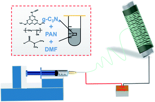 |
| | Scheme 1 Mechanism of diagram electrospinning. | |
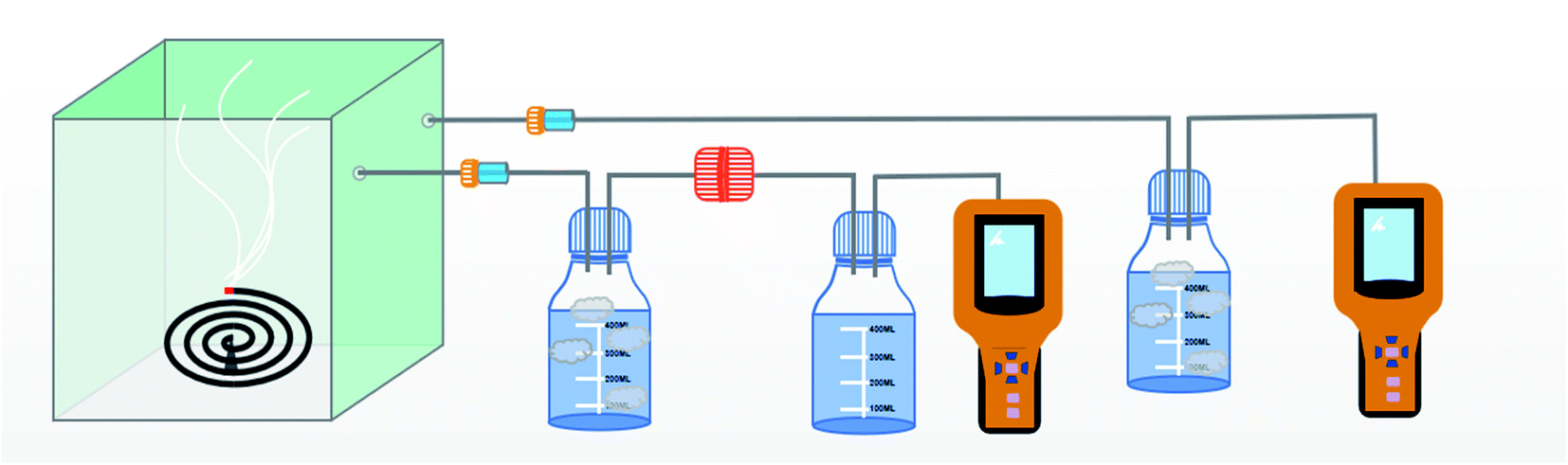
PM generation and evaluation of the filtering efficiency
The schematic of the air filtration set up is given in Scheme 2.12 The particulate matter was produced by burning incense in a closed box connected to two gas detector (Intelligent Gas Detector PGM-300) fitted with peristaltic pump. These detectors measure total particulate matter as well as the PM1, PM2.5, PM5 and PM10 concentration when fitted with air filters of appropriate size. The diameter of the air filters employed in this study is 12 cm. One of the gas detector (GD-2) directly connected to the bottle serves as a control measuring total PM2.5 concentration, in the closed bottle without filtration and the other gas detector (GD-1) connected through the membrane module measuring PM2.5 concentration after filtration.
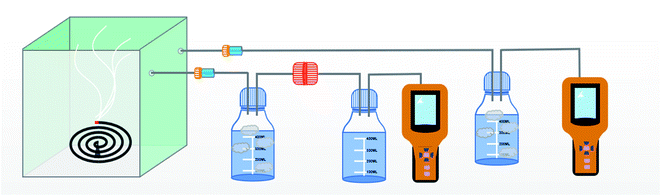 |
| | Scheme 2 Mechanism diagram of PM generation and evaluation of the filtering efficiency. | |
The efficiency of filtration is thus calculated. The data measured by GD-1 is recorded as n1, and the data measured by GD-2 is recorded as n2. The calculation formula of filtration efficiency is as follows: η = (1 − n1/n2) × 100%.13 Further in order to monitor the pressure drop during filtration a differential pressure transmitter (Digital Manometer SD20) was connected across the membrane module as show in Scheme 3. Meanwhile, the quality factor (QF) of air filters employed in this study was calculated as follow:14
where
η is the PM2.5 filtration efficiency and Δ
P is the air drop value across the air filters.
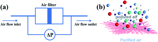 |
| | Scheme 3 Mechanism diagram of the pressure drop test and air filtration model ((a) is mechanism diagram of the pressure drop test and (b) is air filtration model). | |
Evaluation of photocatalytic performance
The methylene blue dye solution (10 mg L−1, 50 mL) was measured into 150 mL quartz test tube, and 0.3 g of fibre film was added. The photocatalyst g-C3N4 and the dye solution reached the equilibrium of adsorption and desorption under the dark condition for 30 min. After the dark reaction, 1.00 mL of the mixed solution was taken, denoted as t = 0 min. Turn on the xenon lamp light source, adjust the power to 15 A, take 1.00 mL of mixed solution every 3 h, which is marked as t = t min, and measure the absorbance of the solution by UV-visible spectrometer (1901PC, Shanghai) in the range of 500–800 nm. According to Lambert–Beer law A = Kbc (where K is the absorption coefficient, in L (g−1 cm−1), b is the distance traveled by the light in the sample (usually the thickness of the cuvette), in cm, c is the concentration of the solution, in g L−1), c1:c2 = A1:A2, with the decrease of absorbance, the concentration also decreased accordingly.15
Characterization
The morphology and structure of the nanofibrous membranes were characterized by field-emission scanning electron microscopy (S-8010, Hitachi, Japan). X-ray diffraction patterns were collected using a Rigaku Ultima IV X-ray diffractometer with Cu Kα X-rays (λ = 0.15418 nm). The fibre diameter distribution was estimated by the statistical analysis of 100 fibres randomly selected by Nano Measure software. Fourier transform infrared (FTIR) spectroscopy was carried out using a Nicolet iS50 instrument (Thermo Fisher Scientific, US). The mechanical properties of the membrane were investigated using a universal strength tester (Instron 6025, Jinan Liangong Testing Technology Co., Ltd., China). The sample was cut into an 8 × 60 mm piece with a thickness of 30 μm, the clamping distance was 20 mm, and the stretching speed was 5 mm min−1. Each sample was subjected to five parallel tests, and the values were averaged.
Results and discussion
Chemical structure of the PAN@g-C3N4 nanofibrous membrane
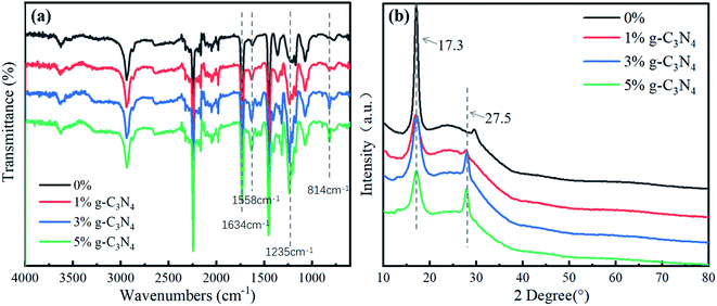
Fig. 1a shows the FTIR spectrum of the nanofibrous membrane, where the peak at 1634 cm−1 represents the C![[double bond, length as m-dash]](https://www.rsc.org/images/entities/char_e001.gif) N stretching vibration. The signal in the range of 1200–1750 cm−1 represents the characteristic peak of CN heterocyclic compounds. This is near 1558 cm−1, which is the peak position of the graphite phase, 1235 cm−1, which is the C–N stretching vibration absorption peak of g-C3N4, and 814 cm−1, which is the characteristic peak of the 3-s-triazine structure.16 With an increase in the content of g-C3N4 in the nanofibrous membrane, the absorption peaks near 1558 cm−1, 1235 cm−1, and 814 cm−1 became stronger, and the peak area gradually increased. Therefore, g-C3N4 was uniformly dispersed and stable in the nanofibrous membrane.
N stretching vibration. The signal in the range of 1200–1750 cm−1 represents the characteristic peak of CN heterocyclic compounds. This is near 1558 cm−1, which is the peak position of the graphite phase, 1235 cm−1, which is the C–N stretching vibration absorption peak of g-C3N4, and 814 cm−1, which is the characteristic peak of the 3-s-triazine structure.16 With an increase in the content of g-C3N4 in the nanofibrous membrane, the absorption peaks near 1558 cm−1, 1235 cm−1, and 814 cm−1 became stronger, and the peak area gradually increased. Therefore, g-C3N4 was uniformly dispersed and stable in the nanofibrous membrane.
 |
| | Fig. 1 The FTIR and XRD of nanofibrous membrane ((a) is FTIR and (b) is XRD). | |
Fig. 1b shows the XRD of the PAN@g-C3N4 composite nanofibrous membrane. The PAN fibre had an obvious strong diffraction peak at 2θ = 17.3°, which is the characteristic diffraction peak of Mellon compounds.17 The crystal standard index was (100). With the addition of g-C3N4, the peak of the (100) crystal plane became weak, and the peak at 2θ = 27.5°, i.e., (002), became stronger, which also indicated that g-C3N4 was dispersed in the PAN composite fibre.
Morphology of the PAN@g-C3N4 nanofibrous membrane
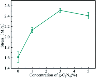
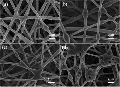
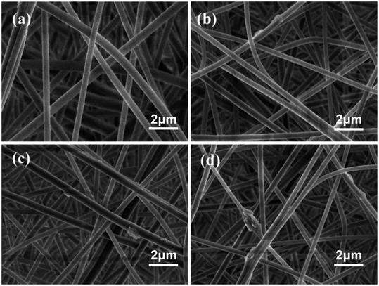
The stability of electrospinning was affected by the lamellar structure of g-C3N4, which led to inhomogeneity of the fibre structure. The morphology of the nanofibrous membrane was also characterised to explain the loading of g-C3N4 on the nanofibrous membrane. Fig. 2 shows the SEM images and Fig. 3 shows the tensile strengths of the PAN@g-C3N4 nanofibrous membranes. With the addition of g-C3N4, smooth PAN fibres appeared as knots, which covered the surface of a single fibre in the form of sheets. With the increase in g-C3N4, the sheet structure gradually increased and nanosheet richness appeared. A tensile testing machine was used to test the breaking strength of the nanofibrous membranes. The obvious enhancement of the mechanical properties of the membrane after the addition of g-C3N4 was due to the structural strengthening caused by the knots.18 However, excessive g-C3N4 aggravated the impurities in the fibre and caused excessive sulfur enrichment at the interface, leading to new shallow energy traps. When g-C3N4 was added at 5%, the fracture strength decreased, confirming this conjecture.
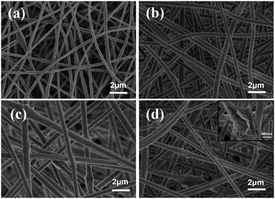 |
| | Fig. 2 SEM image of nanofiber membranes ((a) is pure PAN nanofiber membranes; (b) is PAN@g-C3N4 nanofiber membrane with 1 wt% g-C3N4; (c) is PAN@g-C3N4 nanofiber membrane with 3 wt% g-C3N4; (d) is PAN@g-C3N4 nanofiber membrane with 5 wt% g-C3N4 and the local amplified view). | |
 |
| | Fig. 3 The tensile strengths of the PAN@g-C3N4 nanofibrous membranes. | |
Filtration performance of the PAN@g-C3N4 nanofibrous membrane
Fig. 4 shows the filtration performance of the nanofiber membrane, where (a) is the effect of carbon nitride on the filtration efficiency and filtration pressure of the nanofiber membrane, (b) is the effect of the nanofiber membrane on the filtration stability of PM2.5, (c) is the influence of the weight of the nanofibrous membrane on the filtration performance, and (d) is the influence of the nanofibrous membrane weight on the filter factor. The addition of g-C3N4 significantly improved the filtration performance of the nanofibrous membrane. When the gram weight of the nanofibrous membrane was 0.5 g m−2 and of the amount of added g-C3N4 was 1 wt%, the membrane exhibited a filtration efficiency of 90.21 ± 0.16% and a low pressure drop of 25 ± 0.62 Pa. The improvement in the filtration efficiency may have been due to the reduced fibre diameter and increased specific surface area; further, the surface roughness increased due to the projections, thus increasing the likelihood of a collision between the fibre and intercepted contaminant particles. Further, g-C3N4 is also a good electret, which enhanced the charge storage capacity of the film in this study.19 The increase in charge storage capacity was due to the reorientation of the polar groups in g-C3N4 during the electrospinning process, resulting in the formation of a charge enhancer. Due to different electron transport capabilities at the interface between the polymer and the region, g-C3N4 charge accumulation occurred. Thus, when the charged contaminant particle nanofibrous membrane was formed by PAN, the attractive charges were firmly adsorbed on the fibre, thereby further improving the filtration efficiency of the nanofibrous membrane. Excessive g-C3N4 (i.e., an added amount of 5 wt%) aggravated impurities in the fibre and led to excessive enrichment of the interface.20 This led to new shallow energy traps, resulting in a decrease in the charge storage capacity. In addition, with the agglomeration of g-C3N4, the viscosity and conductivity of the polymer solution, and the increase in the fibre diameter, the filtration performance decreased when the content was 5 wt%. Simultaneously, after cycling, there was no significant reduction in filtration efficiency under a continuous high-concentration environment for 24 hours, indicating that the fibrous membrane had good recycling performance.21
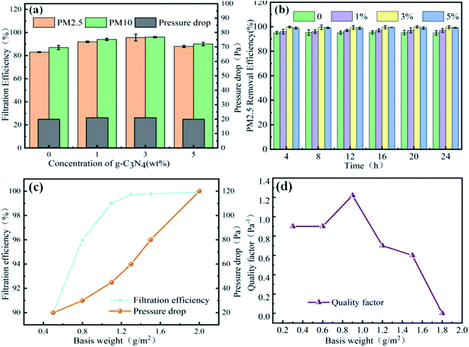 |
| | Fig. 4 Filtration performance of the nanofiber membrane ((a) is filtration efficiency and pressure drop with different g-C3N4 addition, (b) is filtration stability of PM2.5, (c) is filtration efficiency and pressure drop with different weight, (d) is quality factor). | |
As a typical layer-by-layer stacking structure, the pore structure of the nanofibrous membrane is closely related to the thickness of the fibre. The thickness of the membrane is reflected by the basic weight, and there is a negative correlation between the basis weight of the membrane and air permeability. Therefore, by adjusting the basis weight of the membrane, a reasonable balance could be achieved between a high filtration efficiency and low filtration pressure drop. When the unit area weight of the filtration membrane increased from 0.50 g m−2 to 0.75 g m−2, the filtration efficiency increased sharply from 90.2% to 96.0%. The tight packing of fibres improved their ability to intercept and adsorb pollutant particles. When the weight per unit area increased from 1.0 g m−2 to 2.00 g m−2, the filtration efficiency remained approximately constant (99.76 ± 0.3%), and the pressure drop drastically changed from 43 Pa to 120 Pa. Generally, the comprehensive filtration performance is reflected by the quality factor. As can be seen in Fig. 4d, the highest quality factor was 0.121 Pa−1 when the nanofibrous membrane weight was 0.93 g m−2.
Morphology of the PAN@g-C3N4 nanofibrous membrane and captured PM particles
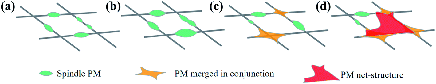
The composition of the smoke produced by burning incense is very similar to the of pollution components in the air. In addition to the presence of fine particles of various sizes, it also includes CO, CO2, NO2, SO2, and volatile organic compounds, such as benzene, toluene, xylene, and aldehyde.22 In addition to polycyclic aromatic hydrocarbons, these components are similar to air pollutants in haze weather; therefore, this experiment used the device, as shown in the figure, as the air filtration system, where the PM particles used were produced by burning sandalwood. To study the mechanism of contaminated air in the nanofibrous membrane filter, we analysed the influence of contaminant particles on the PM nanofibrous membrane morphology. Fig. 5 shows the SEM of nanofibrous membrane with a g-C3N4 addition of 3 wt% filtering polluted air at different duration, and Fig. 6 is a morphology of the particle stacking process. With the extension of the filtering time, the nanofibrous membrane showed fine particles accumulated on the surface of each nanofibrous membrane (Fig. 6a). The particles were stacked on top of tightly wrapped spindle contaminants on the surface of the nanofibrous membrane. The spindle-bonded particulate contaminants then gradually expanded along the fibre direction (Fig. 6b), and the diameter gradually increased such that a crosslinked structure between the fibres occurred (Fig. 6c). With further continued inhalation of smoke, the final morphology of the film resulted in many contaminant aggregates with a mesh structure (Fig. 6d). This was mainly due to the strong surface tension and electrostatic attraction between the charged fine particles and the fibre filter media, the interception effect of Brownian motion, and the electrostatic effect synergistically blocking air pollutants.
 |
| | Fig. 5 SEM of nanofibrous membrane with a g-C3N4 addition of 3 wt% filtering polluted air at different duration ((a) is 1 h, (b) is 3 h, (c) is 5 h, (d) is 8 h). | |
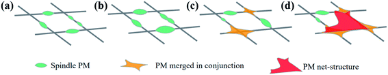 |
| | Fig. 6 Schematic of PAN@g-C3N4 fibrous membrane captured PM particle. (a) is formation of spindle PM, (b) is enlargement of spindle diameter, (c) is the merging of PM in conjunction, (d) is formation of PM net-structure. | |
Photocatalytic properties of the PAN@g-C3N4 nanofibrous membrane
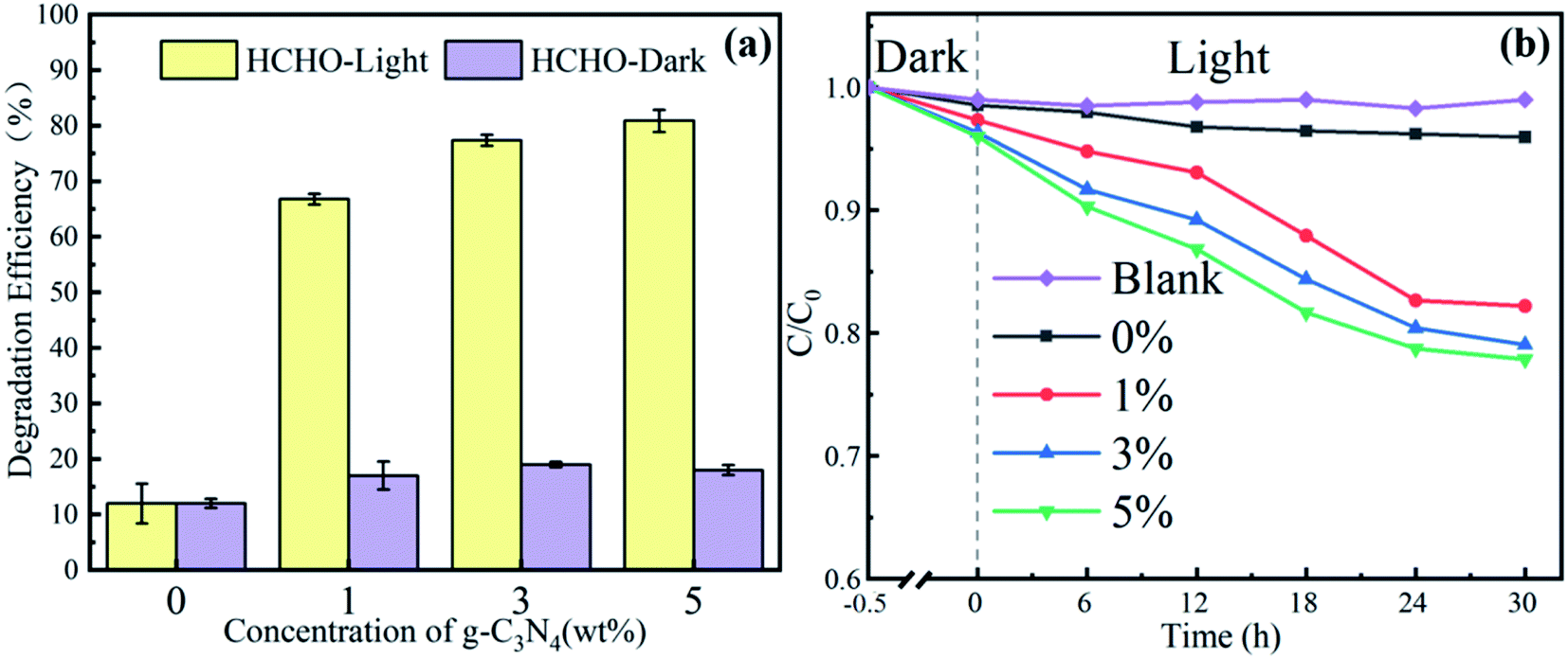
Based on the simulated sunlight photocatalytic properties of g-C3N4, the catalytic degradation performance of the PAN@g-C3N4 nanofibrous membrane on formaldehyde was investigated. Fig. 7a shows the filtration and catalytic degradation experiments of HCHO that were performed under both simulated sunlight radiation and a dark environment. In the dark environment, the nanofibrous membrane adsorbed and intercepted HCHO, and the PAN@g-C3N4 nanofibrous membrane played a role in filtering HCHO, such that the degradation efficiency was low. Therefore, with the addition of g-C3N4, the HCHO defecation performance of the nanofibrous membranes did not significantly increase significantly. Under simulated sunlight irradiation, the HCHO removal efficiency significantly improved. When the g-C3N4 content in the nanofibrous membrane was 3 wt%, the filtration efficiency reached 78.0 ± 1.8%. Simultaneously, the SEM images of the nanofibrous membranes before and after HCHO filtration under simulated sunlight radiation (Fig. 8) showed the morphology of the fibrous membrane, contrasted with Fig. 2, did not significantly change. Therefore, under simulated sunlight irradiation, the nanofibrous membrane adsorbed HCHO molecules, and HCHO was degraded by g-C3N4 on the nanofibrous membrane, leading to its effective removal.
 |
| | Fig. 7 Formaldehyde and methylene blue dye degradation rate of fibrous membrane under both simulated sunlight radiation and a dark environment ((a) is formaldehyde, (b) is methylene blue dye). | |
 |
| | Fig. 8 SEM of fibrous membrane after formaldehyde filtration ((a) is 0 wt%, (b) is 1 wt%, (c) is 3 wt% and (d) is 5 wt%). | |
To further characterise the HCHO removal mechanism of the nanofibrous membrane, the catalytic degradation of methylene blue dye by a nanofibrous membrane under xenon lamp irradiation was investigated, as shown in Fig. 7b. In a dark environment without light radiation, the nanofibrous membrane had a poor ability to remove methylene blue. However, the degradation rate of the pure PAN nanofibrous membrane was 3.45% after 30 h of radiation, and the introduction of g-C3N4 significantly improved the degradation of methylene blue dye to light radiation. The degradation rate of the methylene blue dye increased gradually with an increase in the concentration of g-C3N4. After 30 h of irradiation, the degradation rate of methylene blue dye was 22.39% when the content of g-C3N4 was 5 wt%. Therefore, in the process of dye degradation, the diameter of the nanofibers in the nanofibrous membrane was small, the specific surface area was large, and the dye molecules were quickly adsorbed on the fibre surface. However, the dispersion of g-C3N4 on the fibre surface resulted in photogenerated holes after the absorption of natural light, which oxidised the dye molecules adsorbed on the surface to achieve dye degradation.
Conclusions
In this paper, PAN@g-C3N4 photocatalytic fibrous membrane was successful prepared by electrospinning method. The particle capture ability and formaldehyde filtration mechanism of the nanofibrous membrane were studied. Results show that the addition of g-C3N4 increases the roughness of the fiber, and improves the filtration performance of particulate matter. When the addition amount of g-C3N4 is 3 wt%, the filtration efficiency for PM2.5 reaches 99.76 ± 0.3%, and the filtration efficiency for HCHO reaches 78.0 ± 1.8%. Its catalytic degradation mechanism shows that PAN fiber adsorbs and intercepts HCHO molecules firstly, and then C3N4 dispersed on the surface of the fibre generates photogenerated holes under light irradiation, which oxidizes and degrades formaldehyde molecules to achieve the catalytic degradation. It broadens the application fields of photocatalytic materials and provides new ideas for indoor air filtration materials.
Author contributions
Yahui Cui, completed basic experimental operations and sample performance characterized. Zhenlin Jiang, as the corresponding author, ideas to summarize the integrity of the content are provided and help build the overall writing structure, the final revision of the review was completed. Chenxue Xu, correction and modification in the content of the review writing process. Min Zhu, the review language application, and format was corrected and modified. Weizhen Li, the review language application and format were corrected and modified. Chaosheng Wang, the core concepts of the review were provided and the mid-term content was sorted out, part of the review framework was provided, and the final revision of the review was completed.
Conflicts of interest
There are no conflicts to declare.
Acknowledgements
This work was financially supported by the Young Science and Technology Talent Sailing Project of Shanghai (19YF1417800).
Notes and references
- F. Chen and Z. Chen, Sci. Total Environ., 2021, 755, 142543 CrossRef CAS PubMed.
- Q. Ma, Y. Qi, Q. Shan, S. Liu and H. Hong, Environ. Res., 2020, 189, 109949 CrossRef CAS PubMed.
- Q. Ma, D. Huang, H. Zhang, S. Wang and X. Chen, Int. Immunopharmacol., 2017, 50, 139 CrossRef CAS PubMed.
- Y. Chen, H. Shen, K. R. Smith, D. Guan, C. Chen, G. Shen, J. Liu, H. Cheng, E. Y. Zeng and S. Tao, Environ. Int., 2018, 119, 117 CrossRef CAS PubMed.
- M. E. Yüksekkaya, M. Tercan and G. Doğan, Filtr. Sep., 2010, 47, 36 CrossRef.
- J. H. Park, K. Y. Yoon, H. Na, Y. S. Kim, J. Hwang, J. Kim and Y. H. Yoon, Sci. Total Environ., 2011, 409, 4132 CrossRef CAS PubMed.
- H. S. Park and Y. O. Park, Korean J. Chem. Eng., 2005, 22, 165 CrossRef CAS.
- Y. Su, Z. Zhang, Z. Wang, M. Chen, M. Dong and X. Han, Appl. Surf. Sci., 2017, 425, 220 CrossRef CAS.
- D. Cho, A. Naydich, M. W. Frey and Y. L. Joo, Polymer, 2013, 54, 2364 CrossRef CAS.
- X. Gao, Z. K. Li, J. Xue, Y. Qian, L. Z. Zhang, J. Caro and H. H. Wang, J. Membr. Sci., 2019, 586, 162 CrossRef CAS.
- X. C. Yue, N. L. Ma and C. Sonne, J. Hazard. Mater., 2020, 405, 124138 CrossRef PubMed.
- Y. Xiao, H. Lyu, C. L. Yang, B. B. Zhao, L. Wang and Z. C. Tang, J. Environ. Sci., 2020, 103, 93 CrossRef PubMed.
- M. Faisal, M. Jalalah, F. A. Harraz, A. M. El-Toni, A. Khan and M. S. Al-Assiri, Ceram. Int., 2020, 46, 22090 CrossRef CAS.
- Q. R. Ma, B. Kutilike, N. Kari, A. Shawket and Y. Abliz, Mater. Sci. Semicond. Process., 2021, 121, 105316 CrossRef CAS.
- Z. M. Hao, J. T. Wu, C. L. Wang and J. G. Liu, ACS Appl. Mater. Interfaces, 2019, 11, 11904 CrossRef CAS PubMed.
- O. I. Yakovleva, E. S. Sashina and I. A. Nabieva, Fibre Chem., 2020, 52, 3 Search PubMed.
- Y. H. Zhu, J. Cao, H. Chen, Q. Yu and B. H. Li, J. Mater. Chem. A, 2019, 7, 12 Search PubMed.
- S. Wang, X. L. Zhao, X. Yin, J. Y. Yu and B. Ding, ACS Appl. Mater. Interfaces, 2016, 8, 36 Search PubMed.
- Z. W. Ma, M. Kotaki and S. Ramakrishna, J. Membr. Sci., 2005, 272, 1 Search PubMed.
- Y. Yang, J. Wu and T. Xiao, et al., Appl. Catal., B, 2019, 248, 255 CrossRef.
- Y. Pang, Q. Feng and Z. Kou, et al., Mater. Chem. Front., 2020, 4, 638 RSC.
- J. Liu, T. Wu, Q. Liu, S. Wu and J. Chen, Environ. Pollut., 2020, 262, 114263 CrossRef CAS PubMed.
- J. H. Park, K. Y. Yoon, H. Na, Y. S. Kim, J. Hwang, J. Kim and Y. H. Yoon, Sci. Total Environ., 2011, 409, 4132 CrossRef CAS PubMed.
- A. Amin, A. Akbar, S. Merati, B. Hajir and B. Roohollah, J. Text. Inst., 2017, 108, 9 Search PubMed.
|
| This journal is © The Royal Society of Chemistry 2021 |
Click here to see how this site uses Cookies. View our privacy policy here. 
 Open Access Article
 This Open Access Article is licensed under a Creative Commons Attribution-Non Commercial 3.0 Unported Licence