
 Open Access Article
 This Open Access Article is licensed under a Creative Commons Attribution-Non Commercial 3.0 Unported Licence
Fast conversion of lithium (poly)sulfides in lithium–sulfur batteries using three-dimensional porous carbon†
Xinghua Liang*a,
Xi Wua,
Shuaibo Zeng *b,
Wei Xub,
Xingtao Jianga and
Lingxiao Lana
*b,
Wei Xub,
Xingtao Jianga and
Lingxiao Lana
aGuangxi University of Science and Technology, Guangxi Key Laboratory of Automobile Components and Vehicle Technology, Liuzhou 545006, China. E-mail: lxh304@aliyun.com
bChina School of Automotive and Transportation Engineering, Guangdong Polytechnic Normal University, Guangzhou, 510632, China. E-mail: zsbqiche@163.com
First published on 21st July 2021
Abstract
The slow redox kinetics of polysulfide hinders the rapid and complete conversion between soluble polysulfides and Li2S2/Li2S, resulting in unsatisfactory rate and cycle performance in lithium-sulfur batteries. Electrochemical catalysis, one effective method, promotes the reaction kinetics and inhibits the “shuttle effect”. Here, we present a three-dimensional ordered macro-porous carbon with abundant cobalt–nitrogen–carbon active sites as a matrix catalyst, leading to accelerated polysulfide redox kinetics. In addition, the interconnected conductive frameworks with ordered macro-porous carbon afford fast ion/electron transport and provide sufficient space to adapt to the volume expansion of the sulfur electrode. Owing to the aforementioned advantages, a lithium–sulfur battery with the matrix catalyst delivers a high specific capacity (1140 mA h g−1 at 0.1C) and a low capacity decay rate (0.0937% per cycle over 500 cycles). Moreover, there is a high rate capacity (349.1 mA h g−1) even at the high current density of 2C and sulfur loading of 3.8 mg cm−2 due to the improved polysulfide redox kinetics by a catalytic effect.
Introduction
With the increasing importance of new-energy vehicles powered by lithium-ion batteries, governments all over the world have formulated a timetable for banning the sale of petrol cars to promote the electrification of vehicles.1–3 Within a few short years, various supporting policies were announced to encourage the new-energy automobile industry. However, the actual capacities of automobile power batteries are close to the theoretical capacity of the battery materials, and they still cannot meet the long-cruising demand of electric vehicles.4 Car owners must stop to recharge the batteries during distance driving. The long recharge time and capacity attenuation after multiple charging will thus be an issue. Furthermore, it is difficult for the original battery material system to make a big breakthrough in energy density.5,6 Therefore, new material systems must be developed to meet the ever-changing demands of the new-energy vehicle market.Over the history of the lithium-ion battery, scientists have successively developed a variety of positive, negative, and electrolyte materials.7–11 Compared with the current traditional lithium-ion battery anode materials, sulfur, a geographically ubiquitous element with high theoretical specific capacity (1672 mA h g−1), is regarded as one of the most promising cathode materials for lithium-ion batteries.12–14 However, it still suffers from fatal flaws that delay the pace of engineering application, such as the insulative properties of sulfur and low-order lithium sulfide (Li2S2, Li2S),15,16 solubility of high-order lithium sulfide (Li2S8, Li2S6, Li2S4),17,18 volumetric expansibility during discharge,19,20 and low areal sulfur loading.21,22 These features lead to poor cyclic stability and rate performance.
Many approaches have been proposed to solve the abovementioned problems. Various carbon skeletons have been deployed to hold up sulfur by constructing sulfur–carbon composite materials.23 However, the rate performance of Li–S batteries employed with sulfur/carbon cathode showed no significant improvement due to the lack of interface connectivity and electrical conductivity between particles.24,25 Moreover, dissolution of polysulfide compounds is inevitable because the nonpolar carbon material has only a weak physical restriction on the polar polysulfide.26,27 Furthermore, the slow redox kinetics of polysulfide hinders the rapid and complete conversion between soluble polysulfides and Li2S2/Li2S, which is also an important factor restricting the performance of lithium–sulfur batteries.28–31
Here, we report the preparation of a three-dimensional porous carbon (TDPC) with larger pore volume and electrochemical catalytic activity. Encapsulated sulfur particles in TDPC were synthesized through a removable hard-template method (Fig. 1a). Our electrochemical experiments verified the advantages of TDPC as the sulfur host. Firstly, the abundant uniform mesopores in TDPC enabled high sulfur content (68 wt%), and the high ion conductivity allowed fast ion transfer during the discharge–charge reactions. Secondly, the Co nanoparticles and N-doped carbon composite in TDPC enhanced the catalytic effect, which improved the conversion kinetics between liquid-state Li2S6 and solid-state Li2S. Consequently, the fabricated TDPC@S electrodes were tested for good electrochemistry and featured a high discharge specific capacity of 912.8 mA h g−1 at 1C and a low fading rate of 0.0937% per cycle for 500 cycles.
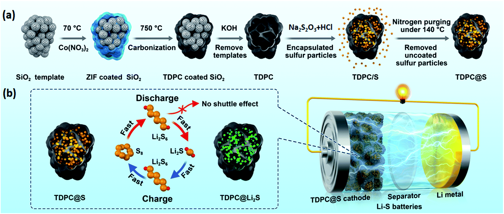 | ||
| Fig. 1 (a) Schematic of the synthetic process for TDPC@S materials, (b) schematic illustration of the effects of TDPC in improving the conversion kinetics between the solid-state polysulfides (Li2S2, Li2S) and liquid-state polysulfides (Li2S8, Li2S6, Li2S4). | ||
Results and discussion
The TDPC@S composite was prepared by the removable template approach illustrated in Fig. 1a. Cobalt nitrate and imidazole ligands were successively mixed with silica nanospheres. A large number of deposition sites were formed on the surface of modified nanospheres, which would be beneficial for the uniform deposition of ZIF-67 in the interspace of silicon nanospheres. In the next steps, a high-temperature carbonization process allowed the production of interconnected carbon skeleton embedded between the silica nanospheres. After template removal by chemical etching, the previous three-dimensional (3D) carbon matrix was not destroyed, maintaining the interconnected mesoporous structure. Then, sulfur element was infused into the structural pores of TDPC to form the TDPC/S composites by a facile melt-diffusion process. Finally, we heated the TDPC/S materials with nitrogen purging to remove the uncoated sulfur particles. This design of TDPC@S exhibits three outstanding beneficial features for the Li–S battery cathode. (i) The robust 3D architecture of TDPC with large surface area and high porosity encapsulates more sulfur, resulting in a higher active material content and providing faster electron transfer and ion diffusion paths; (ii) the TDPC enables spatially controlled deposition of Li2S nanoparticles on the inner surface of the TDPC shell, which effectively prevents the diffusion of soluble polysulfides by physisorption between TDPC and polysulfides; (iii) importantly, the Co nanoparticles and N-doped carbon composite in TDPC function as electrocatalytic sites to accelerate the reversible conversion between high-order lithium polysulfide (Li2S8) and low-order lithium polysulfide (Li2S; Fig. 1b). Benefiting from the aforementioned advantages, the TDPC@S cathodes display a good cycling performance up to 500 cycles.The morphologies and structures of the materials were characterized and analysed by scanning electron microscopy (SEM) combined with energy-dispersive spectrometry (EDS) and transmission electron microscopy (TEM) with elemental mapping. It can be observed that the granuliform SiO2 templates are isolated nanoparticles with a uniform grain size of approximately 400 nm (Fig. 2a). After coating of the packed SiO2 by ZIF, the spherical SiO2 becomes larger and has a dense structure, as shown in Fig. 2b. The EDS clearly reveals the silicon and oxygen element distribution on the ZIF-coated spherical SiO2 (Fig. S1†). As a comparison, there was no silicon element energy spectrum in the EDS spectra after the template was removed, indicating that the SiO2 template has been completely removed by subsequent processes (Fig. S2).† Fig. S3† shows the SEM image of ZIF-coated spherical SiO2 material after carbonization. It is noted that structure of the spherical SiO2 template is not damaged by high temperature. Then, the SiO2 templates were removed by chemical etching technique using KOH as etchant. Fig. 2c shows the SEM image of the obtained TDPC, which presents a good hollow three-dimensional structure. Further study by TEM investigation shows a large number of pore structures inside the TDPC (Fig. 2d). This porous structure can be loaded with more active sulfur, which is conducive to the preparation of high energy density Li–S batteries. At the same time, the high-resolution TEM images also unveil the existence of a mass of cobalt nanoparticles implanted in the TDPC matrix (Fig. 2e and f). To further reveal the elemental distribution within the TDPC matrix, the elemental mappings in overall view and of carbon, cobalt, and nitrogen were performed and are shown in Fig. 2g, demonstrating that there are a large number of holes in the TDPC, and the abovementioned elements are homogenously distributed in the TDPC matrix (Fig. 2h–k). After sulfur impregnation, the obtained TDPC@S maintained the three-dimensional structure (Fig. S4a†). From the elemental mappings shown in Fig. S4b–f,† we clearly observed that the sulfur and cobalt particles are homogenously implanted on the three-dimensional carbon walls.
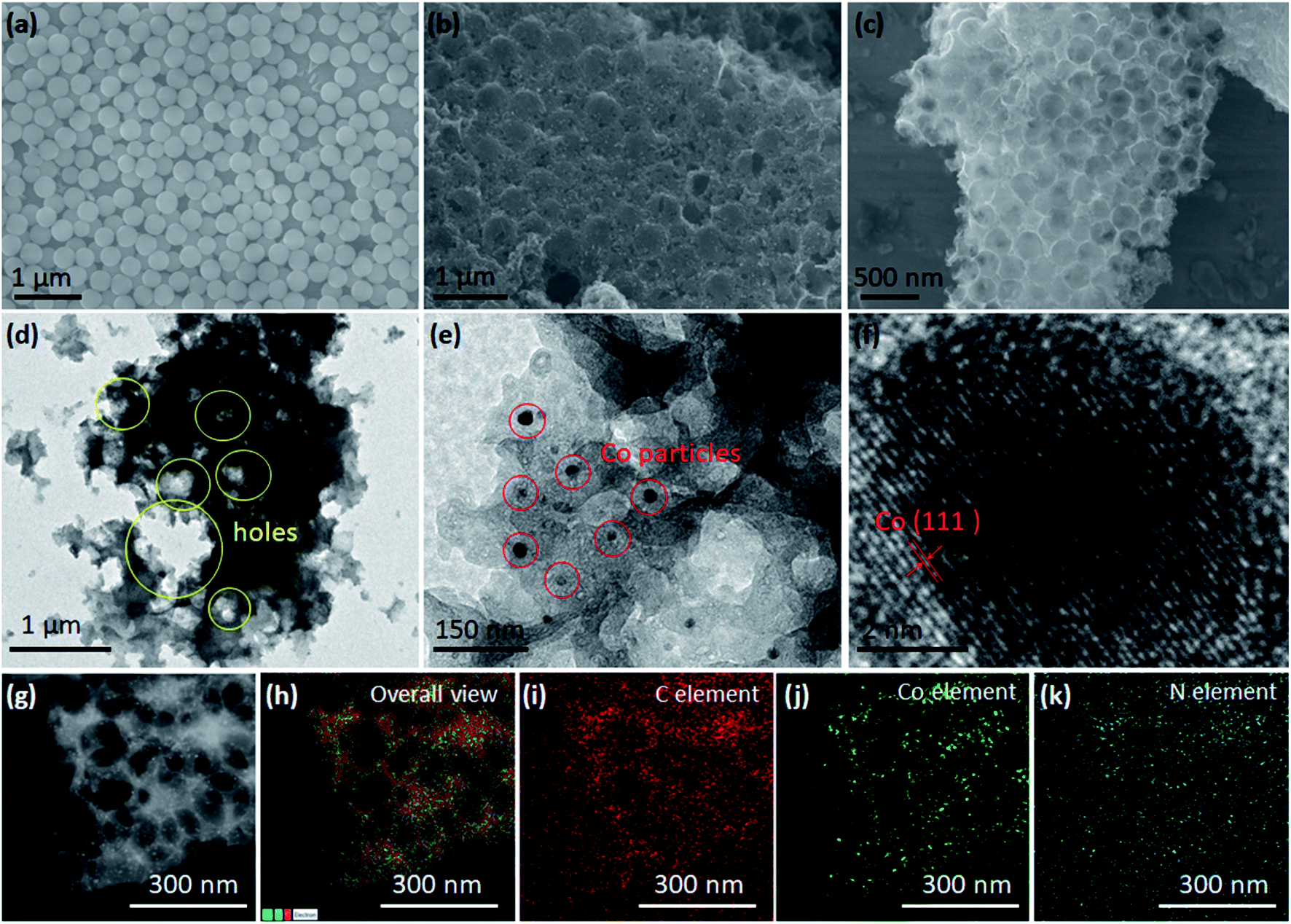 | ||
| Fig. 2 SEM images of (a) SiO2 spherical template, (b) ZIF-coated spherical SiO2, and (c) TDPC. (d–f) TEM images of TDPC. (g) SEM image of TDPC and corresponding elemental maps: (h) overall view, (i) C element, (j) Co element, and (k) N element. | ||
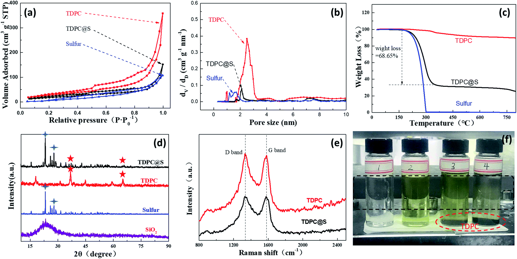
As shown in the nitrogen adsorption–desorption isotherm of the as-prepared TDPC in Fig. 3a, the curves are a type II isotherm associated with an H3 hysteresis loop. The Brunauer–Emmett–Teller (BET) surface area and total pore volume of the TDPC sample are 426.2 m2 g−1 and 0.85 cm3 g−1, respectively, which are higher than those of the TDPC@S sample (43.2 m2 g−1, 0.23 cm3 g−1) because of the introduction of pure sulfur with a smaller pore volume (12.6 m2 g−1, 0.16 cm3 g−1). The corresponding pore size distributions suggest that the three aforementioned samples have hierarchically distributed pores of different sizes, including micropores and mesopores. For quantitative analysis of sulfur content in the TDPC@S sample, thermogravimetric (TG) measurement was performed. From Fig. 3c, the TDPC sample exhibited only a minimal weight loss at the temperature range of 30 °C to 800 °C when it was treated at 800 °C. Meanwhile, the pure sulfur is entirely lost in the temperature range of 150 °C to 300 °C because of sublimation. Thus, it is confirmed that the sulfur content is 68.65% in the TDPC@S composite. X-ray diffraction (XRD) spectrums of the three composites are shown in Fig. 3d. No obvious peaks of SiO2 are observed in the TDPC material, which suggests the SiO2 template has been completely removed. The XRD spectrum of the TDPC@S shows peaks of both TDPC (36.93°) and pure sulfur (23.08°), indicating the presence of both components. The amorphous states of TDPC and TDPC@S were measured by Raman spectroscopy, as shown in Fig. 3e. The intensity ratios between the D band and G band for TDPC and TDPC@S are 1.03 and 1.02, respectively. The above results indicate that introduction of sulfur particles in TDPC did not change the degree of graphitization. An experiment on adsorption of polysulfide lithium was carried out using TDPC, as shown in Fig. 3f. It is obvious that the solution becomes clarified with the addition of TDPC. This phenomenon shows that TDPC has a good adsorption effect for polysulfide lithium. UV-vis spectroscopy defines the liquid intermediates in the discharging process.32,33 We investigated the UV-vis spectra to demonstrate the adsorption of TDPC on lithium polysulfide. The UV-vis spectrum shows the absorption peak at ca. 418 nm for S42− (Fig. S5†), which has been reported in previous literature.34,35 The UV-vis spectrum of solution 4 showed that the absorption peak intensity of S42− was weakened after the addition of TDPC. The evidence above also indicates the adsorption of polysulfide lithium using TDPC. To further investigate the chemical status of carbon, nitrogen, and cobalt elements in the TDPC@S, the full spectrum and high-resolution C 1s, N 1s, and Co 2p spectrums of the TDPC@S sample were illuminated by X-ray photoelectron spectroscopy (XPS). As shown in Fig. 4a, six normal peaks located at 164.43, 227.51, 286.29, 399.37, 533.74, and 799.08 eV were found, which correspond to the binding energy of S 2p, S 2s, C 1s, N 1s, O 1s, and Co 2p.36,37 The surface composition of the elements mentioned above is estimated to be 9.5% for sulfur, 55.7% for carbon, 8.3% for nitrogen, 21.2% for oxygen, and 5.3% for cobalt. From Fig. 4b, the high-resolution C 1s spectrum can be further convoluted into C–C/C![[double bond, length as m-dash]](https://www.rsc.org/images/entities/char_e001.gif) C (284.6 eV), C–N (285.2 eV), and C–O (286.2 eV).38 The high-resolution N 1s spectrum is deconvoluted into four peaks of different signals with binding energies of 398.6, 399.5, 400.6, and 401.3 eV, which are indexed to pyridinic N, pyrrolic N, Co–N, and graphitic N, respectively.39 Peaks at 778.3, 779.6, and 781.5 eV are assigned to metallic Co, Co–O, and Co–N, respectively, which attest to the existence of Co–N bonding.40 Many reports show that the introduction of Co–N bonding and pyridinic-N are beneficial for improving polysulfide redox kinetics.41,42 In the sulfur reduction process, these abundant pyridinic-N and cobalt–nitrogen active sites, as matrix catalyst, accelerate the conversion of lithium polysulfide, leading to enhanced electrode stability.43
C (284.6 eV), C–N (285.2 eV), and C–O (286.2 eV).38 The high-resolution N 1s spectrum is deconvoluted into four peaks of different signals with binding energies of 398.6, 399.5, 400.6, and 401.3 eV, which are indexed to pyridinic N, pyrrolic N, Co–N, and graphitic N, respectively.39 Peaks at 778.3, 779.6, and 781.5 eV are assigned to metallic Co, Co–O, and Co–N, respectively, which attest to the existence of Co–N bonding.40 Many reports show that the introduction of Co–N bonding and pyridinic-N are beneficial for improving polysulfide redox kinetics.41,42 In the sulfur reduction process, these abundant pyridinic-N and cobalt–nitrogen active sites, as matrix catalyst, accelerate the conversion of lithium polysulfide, leading to enhanced electrode stability.43
 | ||
| Fig. 3 (a) Nitrogen desorption curves of as-prepared TDPC, TDPC@S, and pure sulfur; (b) aperture distribution curves of as-prepared TDPC, TDPC@S, and pure sulfur; (c) TGA curves of as-prepared TDPC, TDPC@S, and pure sulfur under an inert atmosphere; (d) XRD patterns of as-prepared TDPC, TDPC@S, pure sulfur, and spherical SiO2; (e) Raman spectra of as-prepared TDPC and TDPC@S; (f) digital photographs of different solutions before and after the addition of various compounds: solution 1, pure electrolyte; solution 2, Li2S added into pure electrolyte; solution 3, TDPC added into solution 2; solution 4, after leaving solution 3 for 30 minutes. | ||
 | ||
| Fig. 4 High-resolution XPS spectra of TDPC: (a) full spectrum, (b) C 1s, (c) N 1s, (d) Co 2p. | ||
The prepared electrode was assembled into a CR2032-type button cell to evaluate the electrochemical performance of TDPC@S as cathode. The TDPC/S cathode and the mixture of sulfur and acetylene black (S/C) cathode were also made into CR2032-type button cells for comparison. Fig. 5a presents the representative electrochemical impedance spectroscopy (EIS) profiles of the batteries with the three aforementioned cathodes at a frequency range of 10−2–105 Hz. According to the equivalent circuit diagram (Fig. S6†), the fitting results show that the TDPC@S electrode has a much smaller Rct than the other two electrodes, indicating that TDPC can effectively facilitate charge transfer and improve the polysulfide redox reactions. To investigate the effects of TDPC on the stability of the electrode, cyclic voltammetry (CV) tests were conducted, as shown in Fig. 5b. The CV profiles display two sulfur reduction peaks, which locate at 2.31 V and 2.03 V in the negative scan, corresponding to the two discharge platforms in Fig. 5d. The fifth CV profile coincides with the first CV profile, verifying that the electrode has good stability. To further evaluate the cycling stability of the Li–S batteries based on TDPC cathode, charge–discharge test was conducted at 0.25C for 100 cycles with a sulfur loading of 3.8 mg cm−2 (Fig. 5c). As shown in Fig. 5d and S7,† the discharge specific capacity of the TDPC@S cathode is 964.36 mA h g−1 at the first cycling. After 100 charge–discharge cycles, the capacity of the electrode dropped to 700.75 mA h g−1, corresponding to a 72.61% capacity retention rate. These values are 60.06% for the TDPC/S cathode and 23.6% for S/C cathode. The potential gap (ΔU) is an important index to evaluate the charge efficiency.44 The ΔU of the TDPC@S electrode is obviously smaller after 100 charge–discharge cycles than that of the other two electrodes, indicating the TDPC@S electrode has a relatively low resistance and polarization. Fig. 5e and f show the rate performance of the three electrodes, which were evaluated at various current densities (from 0.1C to 2C). The discharge specific capacities of the TDPC@S electrode are 1139.2 mA h g−1, 959.9 mA h g−1, 813.5 mA h g−1, 519.6 mA h g−1 and 349.1 mA h g−1 at 0.1, 0.25, 0.5, 1 and 2C, respectively. Those values are 1023.6 mA h g−1, 841.5 mA h g−1, 718.1 mA h g−1, 336.6 mA h g−1, and 151.9 mA h g−1 for the TDPC/S cathode (Fig. S8a†), and 757.8 mA h g−1, 616.0 mA h g−1, 433.1 mA h g−1, 272.1 mA h g−1, and 119.2 mA h g−1 for the S/C cathode (Fig. S8b†) at the relevant rates. More importantly, compared with the other two cathodes, the reversible capacity of the TDPC@S cathode was basically recovered, with the current density back to 0.1C. Such phenomena further prove the TDPC@S cathode has enhanced reaction kinetics.
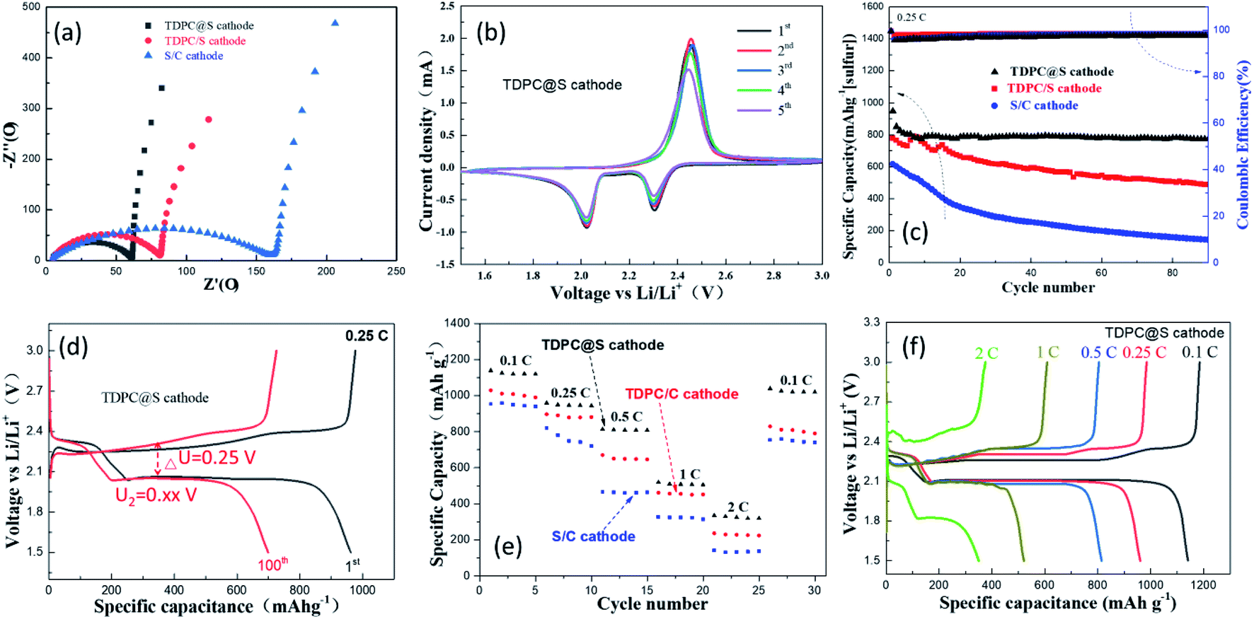 | ||
| Fig. 5 (a) EIS curves of TDPC@S cathode, TDPC/S cathode, and S/C cathode; (b) CV curves of TDPC@S cathode; (c) cycling performance with coulombic efficiency of the TDPC@S, TDPC/S, and S/C cathodes at 0.2C for 100 cycles; (d) charge and discharge curves of the first cycle and the hundredth cycle of the TDPC@S cathode at 0.25C; (e) cyclic stability of the TDPC@S, TDPC/S, and S/C cathodes at different current densities; (f) charge–discharge curves of the TDPC@S cathode at different current densities. | ||
The long-term cycling performance of the three cathodes was tested at a high rate current density of 1C, as shown in Fig. 6. Compared with the other two cathodes, the cycling curve of the TDPC@S cathode exhibits better cycle stability, with the capacity retention of 62.58% after 500 cycles, corresponding to a capacity decay of only 0.0937% per cycle. These values are 0.476% for the TDPC/C cathode and 1.285% for the S/C cathode. These results further validated that the TDPC@S cathode has better cycle stability than the other two cathodes. Table S1† summarizes the performance of sulfur-based cathodes for Li–S batteries in the published literature. Note that the performance of the TDPC@S cathode is better than (or at least comparable to) the leading results reported for other cathodes (Table S1†).
 | ||
| Fig. 6 Cycling performance of TDPC@S, mixture of sulfur and TDPC, and S/C cathodes at 1C over 500 cycles. | ||
Experimental
Synthesis of TDPC and TDPC@S samples
TDPC was synthesized by adopting a procedure based on a removable-template approach.45 In a typical synthesis, 15 mL of deionized water was mixed with 55 mL ethyl alcohol under magnetic stirring. Then, 3 mL of tetraethyl orthosilicate and 4 mL of ammonia were poured into the above solution, respectively. After magnetic stirring for 5 hours, the precipitate was collected by centrifugation at 4000 rpm and washed with deionized water three times. Dry nano-SiO2 particles were obtained after 60 °C heat treatment for 12 hours. Next, 0.873 g of cobalt nitrate hexahydrate was dissolved in 10 mL of anhydrous methanol. The obtained 1.0 g of nano-SiO2 particles were then added into the above solution. After stirring, ultrasonic treatment, and drying, we collected the pink powder. Next, 0.985 g of 2-methylimidazole was dissolved in 10 mL anhydrous methanol, and 1.5 g of the pink powder was added into the anhydrous methanol solution under magnetic stirring. Purple ZIF67@SiO2 composites were obtained after 70 °C heat treatment for 1 hour. Then, we heated the ZIF67@SiO2 composites at 750 °C for 3 hours, and the cooled powder was soaked in KOH (3 M) solution for 8 hours to remove the SiO2 template. Through the above steps, we obtained the TDPC sample.For TDPC@S, firstly, 12.1 g of sodium thiosulfate was dissolved in a mixture of water and ethanol (v/v = 25 mL![[thin space (1/6-em)]](https://www.rsc.org/images/entities/char_2009.gif) :25 mL) under magnetic stirring. Then, 0.3 g of the prepared TDPC was slowly added into the solution. Secondly, 5 mL of diluted hydrochloric acid was added into the solution to form sulfur nanoparticles. We collected the mixture of TDPC and sulfur (TDPC/C) by centrifugation at 8000 rpm for 20 minutes. Lastly, the TDPC@S was obtained after heating at 140 °C for 20 minutes under 200 mL min−1 nitrogen gas flow, which removed the sulfur particles outside the TDPC.
:25 mL) under magnetic stirring. Then, 0.3 g of the prepared TDPC was slowly added into the solution. Secondly, 5 mL of diluted hydrochloric acid was added into the solution to form sulfur nanoparticles. We collected the mixture of TDPC and sulfur (TDPC/C) by centrifugation at 8000 rpm for 20 minutes. Lastly, the TDPC@S was obtained after heating at 140 °C for 20 minutes under 200 mL min−1 nitrogen gas flow, which removed the sulfur particles outside the TDPC.
Materials characterization
The surface morphologies and structures of the prepared samples were analyzed by scanning electron microscopy (SEM) along with energy-dispersive X-ray spectroscopy (Hitachi S-4800), transmission electron microscopy (TEM along with elemental mapping, G2 F20FEI Tecnai G2 F20), and X-ray photoelectron spectroscopy (XPS, PHI). The sulfur content was tested by thermogravimetric analysis (TGA, METTLER) under a N2 atmosphere at a temperature ramp rate of 10 °C min−1. Pore-size distributions and adsorption–desorption isotherms were carried out with a Quadrasorb SIMP apparatus. Raman spectra were performed using an instrument (HORIBA) with an Ar laser source of 633 nm.Electrode and coin-battery assembly
Firstly, 0.02 g of polyvinylidene fluoride (PVDF) was completely dissolved in 2 mL of N-methyl pyrrolidone (NMP). Then, 0.16 g of TDPC@S and 0.2 g of conductive carbon (Super P) were added into the solution to form a uniform slurry. The obtained slurry was cast on the surface of an aluminum film with a thickness of 300 μm. Then, the aluminum film was cut into small round pieces of 12 mm (thickness 0.3 mm, ca. 3.1 mg per disk) in diameter after the slurry was dried. Lastly, coin-type cells (CR 2032) were assembled with TDPC@S as the cathode, a lithium foil (12 mm in diameter, 0.3 mm in thickness) as the anode, Celgard 2400 (14 mm; ca. 1.2 mg per piece) as a diaphragm, and 1.0 mol L−1 lithium bis(trifluoromethanesulfonyl)imide (LiTFSI) with 0.1 mol L−1 of LiNO3 in 1,3-dioxolane and 1,2-dimethoxyethane (v/v = 1:1) as the electrolyte (ca. 13 mg per cell). According to weight and calculation, the sulfur mass loading is around 3.8 mg cm−2.
Electrochemical measurements
The charge–discharge measurements were tested using a CT2001A cell test instrument (Wuhan LAND Electronic Co, Ltd 20 mA). The cyclic voltammetry (CV) and electrochemical impedance spectroscopy (EIS) measurements were conducted with a CHI660E (Shanghai CH Instrument Co, Ltd) electrochemical workstation.Conclusions
In summary, we have successfully synthesized TDPC with a larger pore volume and electrochemical catalytic activity as a new sulfur host for Li–S batteries. With the advantages mentioned above, the TDPC@S composite is loaded with the sulfur content of 68.65% and a high areal mass sulfur loading of 3.8 mg cm−2. Compared with the two other types of cathode, The Li–S batteries with the TDPC@S cathode deliver higher rate capacities and reversible cycling capacities.Conflicts of interest
There are no conflicts to declare.Acknowledgements
This work was supported by the Fund Project of the GDAS Special Project of Science and Technology Development, Guangdong Academy of Sciences Program (No. 2020GDASYL-20200104030); the Innovation Project of Guangxi University of Science and Technology Graduate Education (YCSW2020217); Guangxi Innovation Driven Development Project (No. AA18242036-2); the Fund Project of the Key Lab of Guangdong for Modern Surface Engineering Technology (No. 2018KFKT01); and the Science and Technology Planning Projects of Guangzhou (No. 201803030041).Notes and references
- X. L. Xing, H. B. Dong, S. Y. Zhang, Y. Li, L. X. Liu, D. X. Yu, Y. F. Sheng, C. Y. Yi and G. Han, Energy Storage Sci. Technol., 2020, 9, 239–248 Search PubMed.
- A. Manthiram, X. W. Yu and S. F. Wang, Nat. Rev. Mater., 2017, 2, 16103 CrossRef CAS.
- M. J. Mühlbauer, O. Dolotko, M. Hofmann, H. Ehrenberg and A. Senyshyn, J. Power Sources, 2017, 348, 145–149 CrossRef.
- M. Liu, N. P. Deng, J. G. Ju, L. L. Fan, L. Y. Wang, Z. J. Li, H. J. Zhao, G. Yang, W. M. Kang, J. Yang and B. W. Chen, Adv. Funct. Mater., 2019, 29, 1905467 CrossRef CAS.
- J. H. Kim, Y. H. Lee, S. J. Cho, J. G. Gwon, H. J. Cho, M. Jang and S. Y. Lee, Energy Environ. Sci., 2019, 12, 177 RSC.
- T. Kim, W. T. Song, D. Y. Son, L. K. Ono and Y. B. Qi, J. Mater. Chem. A, 2019, 7, 2942–2964 RSC.
- Y. Z. Song, W. L. Cai, L. Kong, J. S. Cai, Q. Zhang and J. Y. Sun, Adv. Energy Mater., 2019, 1901075 Search PubMed.
- H. Wang, W. Zhang, H. Liu and Z. Guo, Angew. Chem., Int. Ed., 2016, 55, 3992–3996 CrossRef CAS PubMed.
- R. Mo, D. Rooney, K. Sun and H. Y. Yang, Nat. Commun., 2017, 8, 13949 CrossRef CAS PubMed.
- K. Chen, Z. Sun, R. Fang, Y. Shi, H. M. Cheng and F. Li, Adv. Funct. Mater., 2018, 28, 1707592 CrossRef.
- Y. Li, J. Fan, J. Zhang, J. Yang, R. Yuan, J. Chang, M. Zheng and Q. Dong, ACS Nano, 2017, 11, 11417–11424 CrossRef CAS PubMed.
- K. L. Zhu, C. Wang, Z. X. Chi, F. Ke, Y. Yang, A. B. Wang, W. K. Wang and L. X. Miao, Front. Energy Res., 2019, 7, 123 CrossRef.
- X. Gao, Q. Sun, X. Yang, J. Liang, A. Koo, W. Li, J. Liang, J. Wang, R. Li, F. B. Holness, A. D. Price, S. Yang, T. K. Sham and X. Sun, Nano Energy, 2019, 56, 595–603 CrossRef CAS.
- S. Y. Lang, R. J. Xiao, L. Gu, Y. G. Guo, R. Wen and L. J. Wan, J. Am. Chem. Soc., 2018, 140, 8147–8155 CrossRef CAS PubMed.
- D. H. Liu, C. Zhang, G. M. Zhou, W. Lv, G. W. Ling, L. J. Zhi and Q. H. Yang, Adv. Sci., 2018, 5, 1700270 CrossRef PubMed.
- X. J. Liu, T. Qian, J. Liu, J. H. Tian, L. Zhang and C. L. Yan, Small, 2018, 14, 1801536 CrossRef PubMed.
- S. Suriyakumar, S. Gopi, M. Kathiresan, S. Bose, E. B. Gowd, J. R. Nair, N. Angulakshmi, G. Meligrana, F. Bella and C. Gerbaldi, Electrochim. Acta, 2018, 285, 355–364 CrossRef CAS.
- X. J. Yu, G. M. Zhou and Y. Cui, ACS Appl. Mater. Interfaces, 2019, 11, 3080–3086 CrossRef CAS PubMed.
- Y. Xie, G. Y. Pan, Q. Jin, X. Q. Qi, T. Wang, W. Li, H. Xu, Y. H. Zheng, S. Li, L. Qie, Y. H. Huang and J. Li, Adv. Sci., 2020, 7(9), 1903168 CrossRef CAS PubMed.
- Z. W. She, W. Y. Li, J. J. Cha, G. Y. Zheng, Y. Yang, M. T. McDowell, P. C. Hsu and Y. Cui, Nat. Commun., 2013, 4, 1331–1336 CrossRef PubMed.
- H. Kim, J. Lee, H. Ahn, O. Kim and M. J. Park, Nat. Commun., 2015, 6, 7278–7286 CrossRef CAS PubMed.
- K. Park, J. H. Cho, J. H. Jang, B. C. Yu, A. T. De, L. Hoz, K. M. Miller, C. J. Ellison and J. B. Goodenough, Energy Environ. Sci., 2015, 8, 2389 RSC.
- J. Zhang, C. P. Yang, Y. X. Yin, L. J. Wan and Y. G. Guo, Adv. Mater., 2016, 28, 9539–9544 CrossRef CAS PubMed.
- Q. Pang, X. Liang, C. Y. Kwok and L. F. Nazar, Nat. Energy, 2016, 1, 16132 CrossRef CAS.
- M. Agostini and A. Matic, Small, 2019, 1, 1905585 Search PubMed.
- S. B. Zeng, L. G. Li, L. H. Xie, D. K. Zhao, N. Wang and S. W. Chen, ChemSusChem, 2017, 10, 3378–3386 CrossRef CAS PubMed.
- J. Xie, B. Q. Li, H. J. Peng, Y. W. Song, M. Zhao, X. Chen, Q. Zhang and J. Q. Huang, Adv. Mater., 2019, 31, 1903813 CrossRef CAS PubMed.
- C. Zhao, G. L. Xu, T. S. Zhao and K. Amine, Angew. Chem., Int. Ed., 2020, 59(40), 17634–17640 CrossRef CAS PubMed.
- M. Zhao, H. J. Peng, B. Q. Li, X. Chen, J. Xie, X. Y. Liu, Q. Zhang and J. Q. Huang, Angew. Chem., Int. Ed., 2020, 59, 9011–9017 CrossRef CAS PubMed.
- B. Q. Li, L. Kong, C. X. Zhao, Q. Jin, X. Chen, H. J. Peng, J. L. Qin, J. X. Chen, H. Yuan, Q. Zhang and J. Q. Huang, Infomat, 2019, 1(4), 533–541 CrossRef CAS.
- M. Zhao, B. Q. Li, X. Chen, J. Xie, H. Yuan and J. Q. Huang, Chem, 2020, 6(12), 3297–3311 CAS.
- C. Barchasz, F. Molton, C. Duboc, J.-C. Lepretre, S. Patoux and F. Alloin, Anal. Chem., 2012, 84, 3973–3980 CrossRef CAS PubMed.
- Q. He, A. T. S. Freiberg, M. U. M. Patel, S. Qian and H. A. Gasteiger, J. Electrochem. Soc., 2020, 167, 080508 CrossRef CAS.
- H. L. Wu, M. Shin, Y. M. Liu, K. A. See and A. A. Gewirth, Nano energy, 2017, 32, 50–58 CrossRef CAS.
- N. A. Cañas, D. N. Fronczek, N. Wagner, A. Latz and K. A. Friedrich, J. Phys. Chem. C, 2014, 118, 12106–12114 CrossRef.
- X. Peng, K. Huo, J. Fu, X. Zhang, B. Gao and P. K. Chu, Chem. Commun., 2013, 49, 10172–10174 RSC.
- G. Vardar, W. J. Bowman, Q. Y. Lu, J. Y. Wang, R. J. Chater, A. Aguadero, R. Seibert, J. Terry, A. Hunt, I. Waluyo, D. D. Fong, A. Jarry, E. J. Crumlin, S. L. Hellstrom, Y. M. Chiang and B. Yildiz, Chem. Mater., 2018, 30(18), 6259–6276 CrossRef CAS.
- C. Zu and A. Manthiram, Adv. Energy Mater., 2013, 3, 1008–1012 CrossRef CAS.
- C. O. Baker, X. Huang, W. Nelson and R. B. Kaner, Chem. Soc. Rev., 2017, 46, 1510–1525 RSC.
- X. R. Wang, J. Y. Liu, Z. W. Liu, W. C. Wang, J. Luo, X. P. Han, X. W. Du, S. Z. Qiao and J. Yang, Adv. Mater., 2018, 30, 1800005 CrossRef PubMed.
- Y. J. Li, J. B. Wu, B. Zhang, W. Y. Wang, G. Q. Zhang, Z. W. Seh, N. Zhang, J. Sun, L. Huang, J. J. Jiang, J. Zhou and Y. M. Sun, Energy Storage Mater., 2020, 30, 250–259 CrossRef.
- Q. C. Li, Y. Z. Song, R. Z. Xu, L. Zhang, J. Gao, Z. Xia, Z. N. Tian, N. Wei, M. H. Rümmeli, X. L. Zou, J. Y. Sun and Z. F. Liu, ACS Nano, 2018, 12, 10240–10250 CrossRef CAS PubMed.
- R. Wang, J. L. Yang, X. Chen, Y. Zhao, W. G. Zhao, G. Y. Qian, S. N. Li, Y. G. Xiao, H. Chen, Y. S. Ye, G. M. Zhou and F. Pan, Adv. Energy Mater., 2020, 10, 1903550 CrossRef CAS.
- A. Eftekhari, Sustainable Energy Fuels, 2017, 1, 2053 RSC.
- A. I. Douka, Y. Y. Xu, H. Yang, S. Zaman, Y. Yan, H. F. Liu, M. A. Salam and B. Y. Xia, Adv. Mater., 2020, 2002170 CrossRef CAS PubMed.
Footnote |
| † Electronic supplementary information (ESI) available. See DOI: 10.1039/d1ra02704b |
| This journal is © The Royal Society of Chemistry 2021 |