 Open Access Article
In situ fabrication of silver/polyimide composite films with enhanced heat dissipation
So Yoon Leea,
Tae-Hwan Huhb,
Hye Rim Jeongb and
Young-Je Kwark *b
*b
aDepartment of Information Communication, Materials Engineering, Chemistry Convergence Technology, Soongsil University, Seoul, 06978, Republic of Korea
bDepartment of Organic Materials and Fiber Engineering, Soongsil University, Seoul, 06978, Republic of Korea. E-mail: ykwark@ssu.ac.kr
First published on 3rd August 2021
Abstract
In this study, silver/polyimide (Ag/PI) composite films with enhanced heat dissipation properties were prepared. Ag was formed in situ by reducing AgNO3 at various locations according to the reduction method. Two different types of soluble PIs capable of solution processing were used, namely Matrimid and hydroxy polyimide (HPI). Unlike Matrimid with bulky substituents, HPI with polar hydroxy groups formed ion–dipole interactions with Ag ions to form Ag particles with uniform size distribution. The location and distribution of Ag particles affect the heat emission characteristics of the composite films, resulting in better heat dissipation properties with the thermally and photochemically reduced Ag/HPI films having more Ag particles distributed inside of the films than the chemically reduced films.
1. Introduction
Miniaturization of electronic devices has brought about high performance by integrating various functions into a single device.1,2 However, heat generation that shortens the lifetime of the device is inevitable in this process.3–5 In general, a heat sink is used to emit heat from the device. However, physical attachment of the heat sink to the device generates an air gap, which makes it difficult to efficiently dissipate heat.6–8 In order to solve this problem, a layer of a thermal interface material is introduced as an intermediate layer to effectively transmit heat.9–11 In this type of multilayer device, heat conduction can be more efficiently performed in the horizontal direction than the vertical direction. However, in the vertical direction, since the signal of the device is normally operates by being electrically insulated, an electric insulation layer has been separately introduced in the middle of a thermally conductive film in existing research. Since the process of separately forming a thermal conducting layer and an electrical insulating layer is complicated, research on a composite film that exhibits electrical insulation and heat conduction at the same time has been performed.12Existing heat dissipation films use polymers because they have excellent insulation properties and easy processing, and are economical. However, since most polymers have no thermal conductivity, additional fillers such as graphite, carbon fiber, carbon nanotubes, aluminum nitride, aluminum oxide, boron nitride, and silver (Ag) are used to attain sufficient thermal conductivity.13–18 In particular, Ag has high thermal conductivity (429 W m−1 K−1) and low reduction potential (E0 = 0.80 V). Since the reduction potential is low, it is easy to form Ag particles directly in the composites by reducing precursor materials.19,20 Many polymers, such as epoxy,21–24 nano-fibrillated cellulose,25 poly(vinylidene fluoride),26 polytetrafluoroethylene,27 and polyamide,28 are used as a matrix in heat dissipation films. Polyimides (PIs) have been widely used as heat dissipation materials due to their high-performance with excellent mechanical/thermal properties and chemical resistance.29–32 However, the insolubility and infusibility of PIs generally give limitations in preparing metal–PI complexes. As a result, solution processible poly(amic acid) (PAA) has been used as a precursor to PI,33–36 or surface modification with Ag on a PI fiber/film via ion-exchange self-metallization.37–41 PAA provides sufficient processibility to form a composite with well-distributed Ag particles in the entire film, but it requires a subsequent imidization step to form PI. On the other hand, the ion-exchange self-metallization on PI films forms Ag particles on the surface only.
To manufacture metal–polymer composite films, metal particles can be introduced into a polymeric matrix by physical vapor deposition, chemical vapor deposition, or other physical methods (ex situ), or by reducing a metal precursor in organic polymers or their solution (in situ).42–44 The ex situ methods have the advantage of being suitable for mass production in industrial applications, but have the disadvantage of poor dispersibility and/or using other unnecessary additives because of the incompatibility between metal particles and organic polymers.45,46 These problems can be overcome in the in situ methods using metal precursors. The chemical interaction between the metal precursor and organic polymer affects the morphology of the prepared composite and consequently can prevent macroscopic phase separation between the metal filler and the organic polymer matrix. Lin et al. demonstrated that Ag nanoparticles have a uniform particle size distribution due to the ion–dipole interaction between the hydroxy groups of the polymer chains and silver ion (Ag+) in preparing composites from a solution of Ag precursor and poly(vinyl alcohol).47 Even with the chemical interaction, the in situ generated Ag particles preferentially form on the surface of the composites due to the migration of Ag+ ions or Ag metal during the thermal reduction process in the polymer matrix with a lower glass transition temperature (Tg) than the processing temperature.48
In this study, we fabricated Ag/soluble PI (SPI) composite films. Since SPI can be solution processed in its imidized form, the in situ metallization method can be applied without any subsequent imidization process. Moreover, PI has a high Tg above 300 °C, which makes it possible to increase the reduction temperature to 300 °C to induce sufficient reduction of Ag+ ions without causing excessive aggregation of the reduced Ag particles.49–53 We used two different types of SPI, non-polar Matrimid (MI) and polar hydroxy group-containing PI (HPI). MI has a structure that inhibits a planar structure by introducing a bulky substituent, and HPI has a structure which imparts flexibility and polarity to the polymer chain by introducing an electronegative bridging group and hydroxy functional group. The polar hydroxy groups introduce chemical interactions with Ag+ ions to control the distribution of the in situ generated Ag particles.
In addition, we prepared films with three different in situ methods using SPI and an Ag precursor, and these methods are as follows; (1) chemical reduction using reducing agent, (2) thermal reduction at above or below Tg of SPI using a convection oven, and (3) photochemical reduction using a UV lamp. As a result, depending on the reduction method and the presence of polar groups in PI, the size and location of the prepared Ag phase, and eventually the thermal conductivity of the prepared composite film, were affected.
2. Experimental
2.1 Materials and characterization
2,2-Bis(3-amino-4-hydroxyphenyl)hexafluoropropane (bis-ap-af, >98%, Tokyo chemical industry), 4,4'-(hexafluoroisopropylidene)diphthalic anhydride (6FDA, 99%, Sigma-Aldrich), 1-methyl-2-pyrrolidinone (NMP, anhydrous, 99.5%, Sigma-Aldrich), m-xylene (anhydrous, ≥99%, Sigma-Aldrich), and nitric acid silver(I) salt (AgNO3, ≥99%, Sigma-Aldrich) were used without further purification. All other chemicals were obtained from commercial suppliers as first grade and used without further purification. Matrimid (MI), a soluble polyimide, was purchased from Alfa Aesar and used without purification.Fourier-transform infrared (FT-IR, Vertex 70, Bruker) spectra were recorded in the range of 4000–600 cm−1 at a resolution of 2 cm−1. Proton nuclear magnetic resonance (1H-NMR, Advance 400 NMR spectrometer, 400 MHz, Bruker) spectra were obtained using DMSO-d6 as a solvent. Molecular weight and its distribution were measured using gel permeation chromatography (GPC, Waters) with a series of two PL gel Mixed-C columns (5 μm, Agilent) and polystyrene standards (1090–116![[thin space (1/6-em)]](https://www.rsc.org/images/entities/char_2009.gif) 000 Da, Varian). Samples were diluted to about 1% (w/v) in THF and then passed through a 0.45 μm filter before injection. Tg was measured by differential scanning calorimetry (DSC, DSC 25, TA Instruments) under N2. DSC samples of about 5 mg were heated from −90 to 400 °C at a rate of 10 K min−1. The surface and cross-section morphology of the composite film samples were observed by field emission scanning electron microscopy (FE-SEM, Gemini 300, Zeiss) at an accelerating voltage of 3.0 kV for the surface imaging and 15 kV for the cross-sectional imaging. In order to confirm the size and distribution of Ag particles in the Ag/PI composite film, a transmission electron microscope (TEM, JEM-F200, Jeol) was used. The cross-section of the film used for FE-SEM was carved and observed via focused ion beam technology (Crossbeam 540, Zeiss). The thermal dissipation property of the Ag/PI composite film was confirmed using a thermal imaging camera (Ti105, Fluke) by preparing a film with a size of 20 × 20 mm and placing it on a plate of 50 °C. In addition, a Joule heating test was performed to confirm the percolation of Ag particles on the surface of the prepared Ag/PI composite film.
000 Da, Varian). Samples were diluted to about 1% (w/v) in THF and then passed through a 0.45 μm filter before injection. Tg was measured by differential scanning calorimetry (DSC, DSC 25, TA Instruments) under N2. DSC samples of about 5 mg were heated from −90 to 400 °C at a rate of 10 K min−1. The surface and cross-section morphology of the composite film samples were observed by field emission scanning electron microscopy (FE-SEM, Gemini 300, Zeiss) at an accelerating voltage of 3.0 kV for the surface imaging and 15 kV for the cross-sectional imaging. In order to confirm the size and distribution of Ag particles in the Ag/PI composite film, a transmission electron microscope (TEM, JEM-F200, Jeol) was used. The cross-section of the film used for FE-SEM was carved and observed via focused ion beam technology (Crossbeam 540, Zeiss). The thermal dissipation property of the Ag/PI composite film was confirmed using a thermal imaging camera (Ti105, Fluke) by preparing a film with a size of 20 × 20 mm and placing it on a plate of 50 °C. In addition, a Joule heating test was performed to confirm the percolation of Ag particles on the surface of the prepared Ag/PI composite film.
2.2 Synthesis of HPI
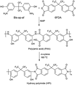
To a three-necked flask were added bis-ap-af (1.36 × 10⁻² mol), 6FDA (1.39 × 10⁻² mol), and NMP (25.4 mL) under a nitrogen atmosphere. The reaction was carried out at room temperature for 12 h with continuous stirring to give PAA. The PAA was dissolved in m-xylene (10 mL), and thermal imidization was carried out at 160 °C for 8 h.54 In this process, water produced by the dehydration reaction was separated using a Dean–Stark trap as an azeotropic mixture with m-xylene. The overall mechanism of the synthesis reaction is shown in Fig. 1. After the completion of the reaction, the solution was dropped into an excess amount of methanol/water (3![[thin space (1/6-em)]](https://www.rsc.org/images/entities/char_2009.gif) :
:![[thin space (1/6-em)]](https://www.rsc.org/images/entities/char_2009.gif) 7) mixture to precipitate a white powder. The resulting powder was dried in a vacuum oven at 130 °C for 24 h to give HPI. The number average molecular weight and polydispersity index of the synthesized HPI were determined using GPC as 36
7) mixture to precipitate a white powder. The resulting powder was dried in a vacuum oven at 130 °C for 24 h to give HPI. The number average molecular weight and polydispersity index of the synthesized HPI were determined using GPC as 36![[thin space (1/6-em)]](https://www.rsc.org/images/entities/char_2009.gif) 500 and 1.41, respectively.
500 and 1.41, respectively.
2.3 Preparation of the Ag/PI composite film
An AgNO3/PI mixed solution was prepared by dropping the AgNO3 solution in dimethylformamide (DMF) (0.05 M) into the PI solution in DMF (15 wt%) at room temperature. The prepared AgNO3/PI solution was cast on a glass slide and pre-baked in a vacuum oven before applying three different reduction processes. In the chemical reduction process, the pre-baked film was immersed in a 0.5 M NaBH4 aqueous solution for 10 min. The film was naturally desorbed from the glass substrate, and dried in an oven at 60 °C for 24 h.55,56 The thermal reduction process was performed by heating the pre-baked film to 300 °C in 1 h and holding it at that temperature for an additional 3 h in an oven under a nitrogen atmosphere. After cooling to room temperature, the film was immersed in distilled water to induce separation from the glass slide, and dried in an oven at 60 °C for 24 h.57,58 In the photochemical reduction process, the pre-baked film was irradiated with a UV/O3 cleaner at a constant wavelength (λabs = 300 to 450 nm) for 30 min. After irradiation, the film was immersed in distilled water, separated from the glass substrate, and dried in an oven at 60 °C for 24 h.59 The overall process is illustrated in Fig. 2.3. Results and discussion
Hydroxy group-containing PI was synthesized by reacting bis-ap-af and 6FDA to form PAA, followed by a thermal imidization process. The overall mechanism of the synthesis reaction is shown in Fig. 1. The number average molecular weight and polydispersity index of the synthesized HPI were determined using GPC to be 36![[thin space (1/6-em)]](https://www.rsc.org/images/entities/char_2009.gif) 500 and 1.41, respectively.
500 and 1.41, respectively.
The chemical structure of HPI was characterized using FT-IR and 1H-NMR. The FT-IR spectrum of HPI shows the absorption bands of the imide carbonyl (C![[double bond, length as m-dash]](https://www.rsc.org/images/entities/char_e001.gif) O) stretching vibration peak and C–N–C bending vibration peak at around 1800 and 1370 cm−1, respectively. Furthermore, the absence of amide carbonyl peaks at 1660 and 1700 cm−1 indicates complete imidization. In addition, it was confirmed that the PI containing hydroxyl groups was synthesized via the O–H stretching vibration peak at 3300 cm−1 (Fig. 3a). The 1H-NMR spectrum also shows the O–H proton and aromatic proton peaks at 10.5 and 7–8 ppm, respectively, suggesting the successful synthesis of HPI (Fig. 3b). The Tg of the synthesized HPI and MI was determined to be 315 and 330 °C, respectively (Fig. 4). The high Tg would be beneficial in applying a high temperature for the thermal reduction process.
O) stretching vibration peak and C–N–C bending vibration peak at around 1800 and 1370 cm−1, respectively. Furthermore, the absence of amide carbonyl peaks at 1660 and 1700 cm−1 indicates complete imidization. In addition, it was confirmed that the PI containing hydroxyl groups was synthesized via the O–H stretching vibration peak at 3300 cm−1 (Fig. 3a). The 1H-NMR spectrum also shows the O–H proton and aromatic proton peaks at 10.5 and 7–8 ppm, respectively, suggesting the successful synthesis of HPI (Fig. 3b). The Tg of the synthesized HPI and MI was determined to be 315 and 330 °C, respectively (Fig. 4). The high Tg would be beneficial in applying a high temperature for the thermal reduction process.
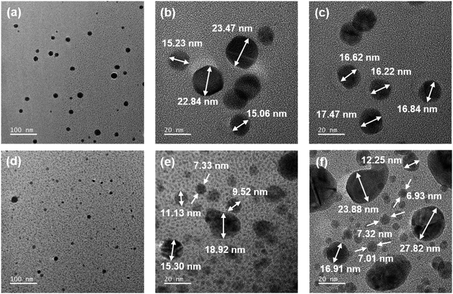
AgNO3/PI films with a thickness of 45–60 μm could be prepared by a solution casting method, and Ag particles were formed in situ by applying three different reduction methods. We expected that the position and size of the reduced Ag particles could be controlled according to the reduction method. In the case of the chemical reduction method, it is expected that Ag particles will be formed on the surface of the composite film because the reduction proceeds only when AgNO3 reacts with the reducing solution present on the film surface. On the other hand, in the case of the thermal and photochemical reduction methods, unlike the chemical reduction method, Ag particles would be uniformly formed in the composite film by applying reducing energy to the entire composite film. In addition, we expected that Ag particles would grow more uniformly inside the HPI matrix due to the ion–dipole interaction between Ag+ and the hydroxyl groups in the Ag/HPI composite film. In the FE-SEM photographs, when the chemical reduction method using NaBH4 aqueous solution was applied, reduced Ag particles were observed on the surface of the film in both the Ag/HPI-C and Ag/MI-C composite films (Fig. 5a and b). In order to confirm the internal Ag distribution of the composite film, we checked the EDS images of the film cross-section. Fig. 6a and b showed that, in both Ag/HPI-C and Ag/MI-C composite films, the element C of the PI was detected in the whole area, while Ag was detected on the surface only. On the other hand, in the case of the Ag/HPI-T and Ag/MI-T, thermally reduced at a temperature below Tg, the Ag particles were seen on the film surface (Fig. 5c and d). Ag particles exposed on the surface of the composite film were observed because the HPI and MI on the surface was corroded by the catalytic effect of Ag particles formed at the beginning of the thermal reduction process. As a result of confirming the cross-sectional morphology of the Ag/MI-T and Ag/HPI-T composite films, Ag particles were found in the entire cross-section of both composite films, but it was found that the Ag/MI-T composite films formed more pronounced Ag surface layers (Fig. 6c and d). This is presumed to be due to the ion–dipole interaction between the hydroxyl groups in the HPI main chain and Ag+ ions, while there is no functional group to interact with the Ag+ ions in MI. To clarify this fact, after thermal reduction at a temperature above Tg of HPI and MI, the cross-sectional morphology and EDS of the composite film were confirmed through FE-SEM. In the cross-sectional morphology of the Ag/HPI-HT and Ag/MI-HT, the overall Ag particle formation pattern was similar to that of Ag/HPI-T and Ag/MI-T, but the surface Ag layer was much thicker than that of Ag/MI-HT and Ag/HPI-HT (Fig. 6e and f). As a result, even if thermal reduction is performed at high temperatures in which both HPI and MI have chain mobility, Ag particles are formed more uniformly in Ag/HPI-HT, indicating that the hydroxyl group in HPI interacts with Ag+ ions. On the other hand, in Ag/HPI-P and Ag/MI-P composite films prepared by the photochemical reduction method, Ag particles were uniformly formed inside the composite film instead of forming an Ag layer on the film surface (Fig. 6g and h). In addition, unlike Ag/HPI-T and Ag/MI-T, Ag particles were not observed on the surface of the Ag/HPI-C and Ag/MI-C composite films, because they did not show the catalytic effect of Ag by thermal treatment and therefore the surface was not corroded (Fig. 5e and f). TEM analysis was performed to confirm the growth of Ag particles according to the presence or absence of a functional group on PI in the composite film prepared by the photochemical reduction method (Fig. 7). In the Ag/HPI-P, Ag particles were stabilized during the growth process due to the hydroxyl groups of the HPI polymer chain to form the particles with a relatively uniform size from 15 to 23 nm. On the other hand, in the Ag/MI-P, although Ag particles were formed inside the film like Ag/HPI-P due to the photochemical reduction method, Ag particles having a very wide distribution size were formed. Through the above results, it was confirmed that the hydroxyl groups could form ion–dipole interactions with Ag+ to control the size of Ag particles inside the film.
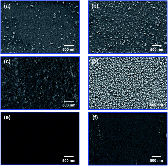 | ||
| Fig. 5 FE-SEM images of the composite film surface of (a) Ag/HPI-C, (b) Ag/MI-C, (c) Ag/HPI-T, (d) Ag/MI-T, (e) Ag/HPI-P, and (f) Ag/MI-P. | ||
 | ||
| Fig. 6 EDS mapping data of the composite film cross-section: (a) Ag/HPI-C, (b) Ag/MI-C, (c) Ag/HPI-T, (d) Ag/MI-T, (e) Ag/HPI-HT, (f) Ag/MI-HT, (g) Ag/HPI-P, and (h) Ag/MI-P. | ||
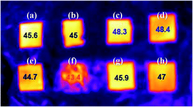
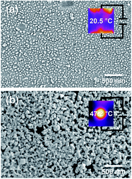
The heat dissipation property of the Ag/PI composite films was tested. Along with the films prepared by chemical, thermal, and photochemical reduction methods, composite films in which the formation of more Ag particles was induced on the surface of the composite film by additional thermal treatment of 300 °C after chemical reduction, Ag/HPI-CT and Ag/MI-CT, were also tested. Fig. 8 shows the surface temperature of the Ag/PI composite films on a hot plate thermostated at 55 °C. Among the Ag/PI composite films tested, Ag/HPI-T and Ag/HPI-P showed the highest temperatures of 48.3 and 48.4 °C, respectively. This is probably because the Ag particles were uniformly formed inside the thermally and photochemically reduced films, as shown in the previous FE-SEM and EDS images. In addition, as confirmed in the TEM image, since the Ag/HPI films formed Ag particles with more uniform size than the Ag/MI films, heat was efficiently conducted and exhibited a higher surface temperature. These results could be interpreted as that heat was transferred by the phonon transfer mechanism inside the composite film,60 and as a result, heat was released in the vertical direction of the film to show almost the same temperature as the underlaying hot plate. On the other hand, the Ag/MI-CT composite film having more Ag particles on the film surface by additional thermal reduction showed the lowest surface temperature. Heat transfer can occur via the electron transfer mechanism as well as phonon transfer. In the case of Ag/MI-CT, it was assumed that heat transfer occurred by the electron transfer mechanism due to the excessive Ag particles formed on the surface to release heat through the horizontal direction of the film. To confirm the electron heat transfer behavior, a Joule heating test was performed (Fig. 9). The Ag/MI-C film showed a lower Joule heating temperature of 20.5 °C due to the small amount of Ag particles, as shown in the FE-SEM images, whereas the Ag/MI-CT film shows a higher Joule heating temperature of 47.2 °C. As a result, as shown in Fig. 8, Ag/MI-CT showed the lowest heating temperature because the heat transfer was performed not only in the vertical direction but also in the horizontal direction of the composite film by the electron heat transfer mechanism.
4. Conclusion
In this study, Ag/PI composite films exhibiting enhanced heat dissipation properties were fabricated by an in situ reduction process using AgNO3 as a Ag precursor. The amount and position of the reduced Ag particles were dependent on the applied reduction method and chemical structure of the matrix polymer, PI. The chemically reduced Ag particles preferentially presented on the surface of the film, whereas the thermally and photochemically reduced Ag particles were formed uniformly inside of the composite film. In addition, Ag particles were distributed more evenly inside the HPI composite film due to the ion–dipole interaction with the hydroxy groups in HPI. It was found that heat dissipation was affected by the position of the reduced Ag particles to give the best result with the Ag/HPI composite films with uniform distribution of Ag particles inside the film. This study confirmed the feasibility of fabricating Ag/PI composite films using a simple process as heat releasing films in microelectronics applications.Author contributions
Lee and Huh contributed equally to this work.Conflicts of interest
There are no conflicts to declare.Acknowledgements
This work was supported by the Soongsil University Research Fund of 2017.Notes and references
- K. Fushinobu, A. Majumdar and K. Hijikata, J. Heat Transfer, 1995, 117, 25 CrossRef CAS.
- Y. He, B. E. Moreira, A. Overson, S. H. Nakamura, C. Bider and J. F. Briscoe, Thermochim. Acta, 2000, 357–358, 1 CrossRef CAS.
- M. R. Krames, O. B. Shchekin, R. Mueller-Mach, G. O. Mueller, L. Zhou, G. Harbers and M. G. Craford, J. Disp. Technol., 2007, 3, 160 CAS.
- L. Meysenc, M. Jylhäkallio and P. Barbosa, IEEE Trans. Power Electron., 2005, 20, 687 CrossRef.
- R. Mahajan, C.-P. Chiu and G. Chrysler, Proc. IEEE, 2006, 94, 1476 Search PubMed.
- R. Viswanath, V. Wakharkar, A. Watwe and V. Lebonheur, Intel Technol. J., 2000, Q3, 1 Search PubMed.
- D. D. L. Chung, J. Mater. Eng. Perform., 2001, 10, 56 CrossRef CAS.
- R. Prasher, Proc. IEEE, 2006, 94, 1571 CAS.
- R. S. Prasher, J. Heat Transfer, 2001, 123, 969 CrossRef CAS.
- L. C. Sim, S. R. Ramanan, H. Ismail, K. N. Seetharamu and T. J. Goh, Thermochim. Acta, 2005, 430, 155 CrossRef CAS.
- N. Han, T. V. Cuong, M. Han, B. D. Ryu, S. Chandramohan, J. B. Park, J. H. Kang, Y.-J. Park, K. B. Ko, H. Y. Kim, H. K. Kim, J. H. Ryu, Y. S. Katharria, C.-J. Choi and C.-H. Hong, Nat. Commun., 2013, 4, 1 Search PubMed.
- S. Mateti, K. Yang, X. Liu, S. Huang, J. Wang, L. H. Li, P. Hodgson, M. Zhou, J. He and Y. Chen, Adv. Funct. Mater., 2018, 28, 1707556 CrossRef.
- Y.-M. Chen and J.-M. Ting, Carbon, 2002, 40, 359 CrossRef CAS.
- S.-Y. Yang, C.-C. Ma, C.-C. Teng, Y.-W. Huang, S.-H. Liao, Y.-L. Huang, H.-W. Tien, T.-M. Lee and K.-C. Chiou, Carbon, 2010, 48, 592 CrossRef CAS.
- W. Wang, X. Yang, Y. Fang, J. Ding and J. Yan, Appl. Energy, 2009, 7–8, 1196 CrossRef.
- X. Zhao and L. Ye, J. Appl. Polym. Sci., 2009, 111, 759 CAS.
- A. Bjorneklett, L. Halbo and H. Kristiansen, Int. J. Adhes. Adhes., 1992, 12, 99 CrossRef CAS.
- H. Yu, L. Li and Y. Zhang, Scr. Mater., 2012, 66, 931 CrossRef CAS.
- G. Liao, J. Chen, W. Zeng, C. Yu, C. Yi and Z. Xu, J. Phys. Chem. C, 2016, 120, 25935 CrossRef CAS.
- G. Liao, Q. Li, W. Zhao, Q. Pang, H. Gao and Z. Xu, Appl. Catal., A, 2018, 549, 102 CrossRef CAS.
- A. Yu, P. Ramesh, M. E. Itkis, E. Bekyarova and R. C. Haddon, J. Phys. Chem., 2007, 111, 7565 CAS.
- S. H. Song, K. H. Park and B. H. Kim, Adv. Mater., 2013, 25, 732 CrossRef CAS PubMed.
- X. Huang, C. Zhi and P. Jiang, J. Phys. Chem. C, 2012, 116, 23812 CrossRef.
- M. A. Raza, A. V. K. Westwood, C. Stirling and R. Ahmad, Compos. Sci. Technol., 2015, 120, 9 CrossRef CAS.
- Z. Shen and J. Feng, ACS Appl. Mater. Interfaces, 2018, 10, 24193 CrossRef CAS PubMed.
- Z. Li, L. Zhang, R. Qi, F. Xie and S. Qi, J. Appl. Polym. Sci., 2016, 133, 43554 Search PubMed.
- H. Jung, S. Yu, N.-S. Bae, S. M. Cho, R. H. Kim, S. H. Cho, I. Hwang, B. Jeong, J. S. Ryu, J. Hwang, S. M. Hong, C. M. Koo and C. Park, ACS Appl. Mater. Interfaces, 2015, 7, 15256 CrossRef CAS PubMed.
- D. Parida, P. Simonetti, R. Frison, E. Bülbül, S. Altenried, Y. Arroyo, Z. Balogh-Michels, W. Caseri, Q. Ren, R. Hufenus and S. Gaan, Chem. Eng. J., 2020, 389, 123983 CrossRef.
- Q. Li, G. Lia, S. Zhang, L. Pang, H. Tong, W. Zhao and Z. Xu, Appl. Surf. Sci., 2018, 427, 437 CrossRef CAS.
- Q. Li, G. Liao, J. Tian and Z. Xu, Macromol. Mater. Eng., 2018, 303, 1700407 CrossRef.
- Q. Li, R. Chen, Y. Guo, F. Lei, Z. Xu, H. Zhao and G. Liao, Polymers, 2020, 12, 88 CrossRef CAS PubMed.
- Y. Li, Y. Zhu, G. Jiang, Z. P. Cano, J. Yang, J. Wang, J. Liu, X. Chen and Z. Chen, Small, 2020, 16, 1903315 CrossRef CAS PubMed.
- Q. Zhang, D. Wu, S. Qi, Z. Wu, X. Yang and R. Jin, Mater. Lett., 2007, 61, 4027 CrossRef CAS.
- D. S. Thompson, L. M. Davis, D. W. Thompson and R. E. Southward, ACS Appl. Mater. Interfaces, 2009, 1, 1457 CrossRef CAS PubMed.
- A. V. Gaikwad and T. K. Rout, J. Mater. Chem., 2011, 21, 1234 RSC.
- M. Zhang, J. Li, L. Kang, N. Zhang, C. Huang, Y. He, M. Hu, X. Zhou and J. Zhang, Nanoscale, 2020, 12, 3988 RSC.
- B. Carlberg, L.-L. Ye and J. Liu, Mater. Lett., 2012, 75, 229 CrossRef CAS.
- D. Y. Zhang, J. Liu, Y. S. Shi, Y. Wang, H. F. Liu, Q. L. Hu, L. Su and J. Zhu, J. Membr. Sci., 2016, 516, 83 CrossRef CAS.
- W. Chunbo, L. Liaoliao, J. Haifu, T. Dongbo, Q. Wei, L. Changwei, Z. Xiaogang, C. Chunhai and W. Daming, RSC Adv., 2018, 8, 21728 RSC.
- P. Bi, X. Liu, Y. Yang, Z. Wang, J. Shi, G. Liu, F. Kong, B. Zhu and R. Xiong, Adv. Mater. Technol., 2019, 4, 1900426 CrossRef CAS.
- R. Li, X. Lv, J. Yu, X. Wang and P. Huang, High Perform. Polym., 2020, 32, 1181 CrossRef CAS.
- G. Liao, Y. Gong, C. Yi and Z. Xu, Chin. J. Chem., 2017, 35, 1157 CrossRef CAS.
- L. Xiao, M. Deng, W. Zeng, B. Zhang, Z. Xu, C. Yi and G. Liao, Ind. Eng. Chem. Res., 2017, 56, 12354 CrossRef CAS.
- G. Liao, J. Fang, Q. Li, S. Li, Z. Xu and B. Fang, Nanoscale, 2019, 11, 7062 RSC.
- Z. Yuan, N. H. Dryden, J. J. Vittal and R. J. Puddephatt, Chem. Mater., 1995, 7, 1696 CrossRef CAS.
- P. F. Green and L. L. Berger, Thin Solid Films, 1993, 224, 209 CrossRef.
- S. Lin, R. Z. Wang, Y. Yi, Z. Wang, L. M. Hao, J. H. Wu, G. H. Hu and H. He, Int. J. Nanomedicine, 2014, 9, 3937 CrossRef PubMed.
- C.-G. Yuan, S. Guo, J. Song, C. Huo, Y. Li, B. Gui and X. Zhang, RSC Adv., 2017, 7, 4830 RSC.
- C. E. Sroog, Prog. Polym. Sci., 1991, 16, 561 CrossRef CAS.
- L. Zhai, S. Yang and L. Fan, Polymer, 2012, 53, 3529 CrossRef CAS.
- W. Volksen, R. D. Miller and G. Dubois, Chem. Rev., 2010, 110, 56 CrossRef CAS PubMed.
- J. Y. Do, S. K. Park, J.-J. Ju, S. Park and M.-H. Lee, Macromol. Chem. Phys., 2003, 204, 410 CrossRef CAS.
- B. S. Ghanem, R. Swaidan, E. Litwiller and I. Pinnau, Adv. Mater., 2014, 26, 3688 CrossRef CAS PubMed.
- T. Omote, K. Koseki and T. Yamaoka, Macromolecules, 1990, 23, 4788 CrossRef CAS.
- H.-L. Jiang and Q. Xu, J. Mater. Chem., 2011, 21, 13705 RSC.
- L. B. Devi and A. B. Mandal, RSC Adv., 2013, 3, 5238 RSC.
- R. E. Southward and D. W. Thompson, Chem. Mater., 2004, 16, 1277 CrossRef CAS.
- Y. Zhao, Q. Lu, D. Chen and Y. Wei, J. Mater. Chem., 2006, 16, 4504 RSC.
- S. N. Ostad, S. Dehnad, Z. E. Nazari, S. T. Fini, N. Mokhtari, M. Shakibaie and A. R. Shahverdi, Avicenna J. Med. Biotechnol., 2010, 2, 187 CAS.
- A. Li, C. Zhang and Y.-F. Zhang, Polymers, 2017, 9, 437 CrossRef PubMed.
| This journal is © The Royal Society of Chemistry 2021 |

