
 Open Access Article
 This Open Access Article is licensed under a Creative Commons Attribution-Non Commercial 3.0 Unported Licence
Acid-treated multi-walled carbon nanotubes as additives for negative active materials to improve high-rate-partial-state-of-charge cycle-life of lead-acid batteries†
Li
Dong
ab,
Chunhua
Chen
a,
Jiejie
Wang
a,
Hongwei
Li
a,
Hui
Zheng
a,
Wei
Yan
*a,
Joey
Chung-Yen Jung
 a and
Jiujun
Zhang
*a
a and
Jiujun
Zhang
*a
aInstitute for Sustainable Energy, College of Sciences, Shanghai University, Shanghai, 200444, P.R. China. E-mail: yveayan@shu.edu.cn; jiujun.zhang@i.shu.edu.cn
bZhaoqing Leoch Battery Technology Co. Ltd., Guangdong Province, 518000 China
First published on 23rd April 2021
Abstract
In this work, a trace amount of acid-treated multi-walled carbon nanotubes (a-MWCNTs) is introduced into the negative active materials (NAMs) of a lead acid battery (LAB) by simply dispersing a-MWCNTs in the water, which is then added into the dry mixture of lead oxide powder, expanders and carbon black for lead paste preparation. The abundant oxygen-containing groups on the a-MWCNTs show significant influence on the chemical reactions happening during the curing process, leading to the improved properties of NAMs. Specifically, after formation, the NAMs containing 100 ppm a-MWCNTs display a spongy-like structure comprised of interconnected domino-like Pb slices, giving favorable porosity and electroactive surface area of the NAMs. Moreover, the quasi-rod structure of Pb slices provides the channels for fast electron transfer. These two features greatly accelerate the electrochemical reaction between Pb and PbSO4, and hence hinder the accumulation of PbSO4 crystals. As a result, the high-rate partial-state-of-charge (HRPSoC) cycle-life of the simulated cell constructed from the a-MWCNTs-containing negative plate achieves a HRPSoC cycle-life more than 1.5 times longer than the cell constructed when the negative plate contains only carbon black. Since our method is of great convenience and low-cost, it is expected to have a great feasibility in the LAB industry.
1. Introduction
Recently, the fast consumption of the reserves-limited fossil fuels and the associated environmental pollution have spurred people to explore clean and sustainable energy sources such as solar, wind, waterfall, geothermal, etc. To store and smooth the intermittent electricity energy generated from these energy sources for applications, the electrochemical energy storage and conversion technologies such as batteries, fuel cells, supercapacitors, water electrolysis, etc. have been recognized as the most efficient, reliable, and practical devices. Regarding practically usable rechargeable batteries, including lithium-ion batteries, lead acid batteries (LAB), nickel-hydrogen batteries, etc., LAB still occupies the largest market due to it having the most mature industrial manufacture process, reliability and safety, the lowest-cost, and the almost full recyclability of the spent battery when compared to other types of batteries.1,2 However, the relatively low energy density and insufficient cycle-life of LAB have been identified to be the limitation. Particularly, when LAB is applied in the scenario of hybrid vehicles, it has to be operated under the high-rate partial-state-of-charge (HRPSoC) condition, implying that the battery will experience short charge and discharge events with large currents and should have an extremely long cycle-life.3 Therefore, prolonging the HRPSoC cycle-life of a LAB is one of the most important requirements specifically for applications of the hybrid vehicles, meaning that further research and development for further improving the HRPSoC performance of the LAB is necessary.One of the major challenges liming the HRPSoC cycle-life of a LAB has been identified to be that during the HRPSoC duty, the PbSO4 crystals on the negative plates could not be effectively converted back to Pb, such nonconductive PbSO4 crystals would gradually accumulate on the surface of negative plates, decreasing the charge acceptance of negative plates, and leading to degradation and eventually failure of the battery.4 Therefore, accelerating the electrochemical reduction of PbSO4 to Pb should be the major approach in improving HRPSoC cycle-life of a LAB. According to Palvov and Nikolov,5 the reduction of PbSO4 crystals obeys the “dissolution-precipitation” mechanism. Firstly, PbSO4 crystals are dissolved and dissociated into Pb2+ and SO42− ions, as expressed by eqn (1). Then, Pb2+ ions receive electrons from the negative plates and are reduced into Pb atoms (eqn (2)), while the SO42− ions react with protons to form H2SO4 (eqn (3)).
| PbSO4 → Pb2+ + SO42− | (1) |
| Pb2+ + 2e− → Pb | (2) |
| SO42 + 2H+ → H2SO4 | (3) |
Based on eqn (1)–(3), the effective strategies to address the accumulation issue of PbSO4 crystals on the negative plates should be to increase the solubility of PbSO4 by decreasing the size of PbSO4 crystals, to accelerate the reduction of Pb2+ ions by increasing the surface area and charge transfer ability of negative active materials (NAMs), and to facilitate the combination of SO42− and protons by promoting the diffusion of SO42− ions.
In the effort to accelerate the electrochemical reduction of PbSO4 to Pb, it has been found that adding carbon additives can effectively alleviate the sulfation issue of negative plates through speeding up all reactions expressed by eqn (1)–(3). As identified, the functions of carbon additives can be summarized as follows: (1) offering extra nucleation sites to form small PbSO4 crystals and meanwhile acting as the spacer to restrict the growth of particles;5,6 (2) increasing both the surface area and conductivity of to accelerate the electrochemical reduction of Pb2+ ions;7,8 and (3) increasing the porosity of NAMs to promote the diffusion of SO42− ions and facilitating the combination of SO42− and H+ ions.9,10 In particular, it is worth to mention that the increased porosity of NAMs allow SO42 ions to diffuse into the interior of, leading to the formation of small PbSO4 crystals throughout the negative plates instead of accumulation of large PbSO4 crystals on the surface of plates.11,12 With respect to this, various carbon materials, such as graphite,13–15 activated carbons,5,7,16 carbon nanotubes (CNTs)15,17 and graphene5,15,18 have been explored as the additives for NAMs, and the HRPSoC cycle-life of LAB have been improved after introduction of these carbon materials.19,20
CNTs are an allotrope of carbon and possess many unique structural, mechanical, thermal and electronic properties, which have been widely explored as the material for electrochemical energy storage and conversion devices such as batteries,21–23 supercapacitors24,25 and fuel cells.26 Many researchers also tried to incorporate CNTs into NAMs to improve the performance of LAB for start-stop battery of automobiles.6,27–32 Few researches have tried to improve the HRPSoC performance of LAB as the auxiliary power for hybrid vehicles.15,32,33 For example, 0.25 wt% CNTs were introduced into the negative lead paste as the only carbon additives by dry mixing CNTs with lead oxide powder and expanders before blending with water and sulfuric acid. Compared to the conventional LAB which contains 0.2 wt% carbon black in NAMs, the HRPSoC cycle-life with 0.25 wt% CNTs were greatly improved. However, the relatively high-cost of CNTs has impeded their large-scale application in LAB industry. In our previous study, we have successfully improved the HRPSoC cycle-life through incorporating a small amount of graphene oxide nanosheets into conventional negative lead paste by simply blending the dry mixture of lead oxide powder, expanders and carbon black with aqueous dispersion of graphene oxide nanosheets. During the formation process, the trace amount of graphene oxide nanosheets could induce the growth of one-dimensional (1D) porous Pb sticks. Such 1D structure of Pb sticks could provide fast electron transport channel, while the pores on Pb sticks and the voids among Pb sticks could facilitate electrolyte transportation. As a result, the accumulation of PbSO4 crystals was suppressed, and the HRPSoC cycle-life was greatly improved. Furthermore, the hydrogen evolution rate on the cathode was not changed by the adding of graphene oxide nanosheets in NAMs probably due to the content of graphene oxide nanosheets was too low.34 However, despite only 2 ppm of graphene oxide nanosheets were introduced into the negative lead paste, the high-price and low availability of graphene products still not favorable for large-scale application.
In this work, a trace amount of multi-walled CNTs (MWCNTs), which are cheaper and also higher available than graphene oxide nanosheets, is added into conventional negative lead paste to improve the HRPSoC cycle-life of LAB. The negative lead paste is made by dispersing acid-treated MWNCTs (a-MWCNTs) in water, and blended with the dry mixture of lead oxide paste, expanders and carbon black, followed by addition of H2SO4 drop by drop. As a-MWCNTs carry abundant oxygen-containing groups on their surfaces, which will react with other substances in negative lead paste. The incorporation of even trace amount of a-MWCNTs has a great effect on the morphology of the formed NAMs. When 100 ppm a-MWCNTs is introduced, the formed NAMs presented a spongy-like structure consisted of interconnected domino-like Pb slices, which increases the porosity and surface area of the NAMs. In addition, the quasi-rod structure of Pb slices offers channels for fast electron transfer. Thus, the electrochemical transformation between Pb and PbSO4 is accelerated, and the accumulation of PbSO4 crystals is hindered. The HRPSoC cycle-life of the simulated cell increases by more than 150% from 21![[thin space (1/6-em)]](https://www.rsc.org/images/entities/char_2009.gif) 328 to 32010 cycles. It is believed that our method will find a great value in LAB industry.
328 to 32010 cycles. It is believed that our method will find a great value in LAB industry.
2. Experimental
2.1. Materials
Lead oxide powder (oxidation degree = 72%), vanisperse A and Vulcan carbon XC-72R (VC-72) were provided by Leoch International Technology Co. Ltd. (Shenzhen, China). MWCNTs were bought from Nanjing XFNANO Materials Tech Co. Ltd. (Nanjing, China). Sulfuric acid (H2SO4, 98%), nitric acid (HNO3, 56%) and barium sulfate (BaSO4) were purchased from Sinopharm Chemical Reagents Co. Ltd. (Shanghai, China). All reagents were used as received without further purification, and distilled water was used throughout the experiments.a-MWCNTs were prepared by refluxing MWCNTs in nitric acid for several hours to remove the impurities. In the meantime, the surfaces of MWCNTs were functionalized with abundance of oxygen-containing groups. After refluxing, the a-MWCNTs were washed by distilled water and centrifuged until a neutral pH. The a-MWCNTs were then re-dispersed in water to obtain an aqueous suspension of 5 mg mL−1.
2.2. Preparation of negative plates and assembly of the simulated batteries
The preparation of negative plates and the assembly of simulated cells are shown in Scheme 1. Negative lead paste was prepared by dry mixing lead oxide powder, VC-72, BaSO4 and vanisperse A in a mass ratio of 100:0.2:0.2:0.8. Then, a certain volume of a-MWCNTs aqueous suspension was dispersed in water and added to the dry mixture very quickly. After several minutes of blending, H2SO4 (1.4 g cm−3) was added dropwise to form the negative lead paste. The negative plates were prepared by manually coating 6.0 g negative paste on a Pb–Sn–Ca grid (45 mm × 26 mm), and then subjected to commercial curation and formation processes. Negative plates of P000, P050, P075, P100 and P125 were obtained by dispersing different volume of a-MWCNTs aqueous dispersion in water, and the mass ratios of a-MWCNTs to lead oxide powder were 0, 50 ppm, 75 ppm, 100 ppm and 125 ppm, respectively. Table 1 lists the compositions of additives in each plate.
 | ||
| Scheme 1 Schematic diagram of the preparation process of the negative plate and the assembly of the simulated cell. | ||
| Negative plates | Expanders | VC-72 | a-MWCNTs |
|---|---|---|---|
| P000 | 0.2 wt% BaSO4 + 0.8 wt% vanisperse A | 0.2 wt% | 0 |
| P050 | 0.2 wt% BaSO4 | 0.2 wt% | 50 ppm |
| 0.8 wt% vanisperse A | |||
| P075 | 0.2 wt% BaSO4 | 0.2 wt% | 75 ppm |
| 0.8 wt% vanisperse A | |||
| P100 | 0.2 wt% BaSO4 | 0.2 wt% | 100 ppm |
| 0.8 wt% vanisperse A | |||
| P125 | 0.2 wt% BaSO4 | 0.2 wt% | 125 ppm |
| 0.8 wt% vanisperse A |
The 2 V/0.75 A h simulated cells were assembled with one negative plate and two commercial positive plates which were separated by 1.5 mm thick absorbent glass mat (AGM) separator. Thus, the performance of the simulated batteries was decided by the negative plate. The simulated cells assembled with P000, P050, P075, P100 and P125 are referred as C000, C050, C075, C100 and C125, respectively.
2.3. Characterization
Transmission electron microscopy (TEM) images were acquired using a JEM-200CX transmission electron microscope operated at an acceleration voltage of 120 KeV. Scanning electron microscopy (SEM) images were obtained using field-emission scanning electron microscope (FE-SEM, Hitachi S-4800). Fourier transform infrared spectroscopic (FTIR) measurements were performed on a Nicolet Avatar370 FTIR instrument (Thermo Nicolet, USA) using KBr pellets. Powder X-ray diffraction (XRD) measurements were performed on a 18 KW D/MAX2500V+/PC instrument using a graphite monochrometer with Cu Ka radiation (k = 1.5406 Å).2.4. Electrochemical measurements
The cyclic voltammograms of negative plates were recorded in H2SO4 (1.28 g cm−3) using a three-electrode electrochemical cell on a Metrohm Multi Autolab/M204 potentiostat equipped with a booster. The potential was scanned between 0 and −1.5 V at 1 mV s−1. In the cell, a negative plate was used as the working electrode, and a commercial positive plate and a Hg/Hg2SO4 electrode were used as the counter electrode and reference electrode, respectively. Electrochemical impedance spectroscopy (EIS) was carried out at the open circuit potential (OCP) with a frequency ranging from 0.1 to 10 kHz with a voltage perturbation of 5 mV amplitude. Peukert plot was obtained by measuring the capacities of the simulated cell at different currents to determine the 1C current for HRPSoC tests.Before HRPSoC tests, the simulated cells were first charged at C10 rate to 2.45 V, followed by a floating charge at 2.45 V for another 18 hours. Then the simulated cells were discharged at 1C rate to 50% state of charge (SoC). The HRPSoC tests were performed based on a simplified profile imitating micro-hybrid driving mode, which comprised charge and discharge pulses at 1C current according to the following schedule: charging at 1C rate for 30 seconds, rest for 10 seconds, discharging at 1C rate for 30 seconds, rest for 10 seconds.5 The tests were stopped when the end-of-discharge voltage (Vdischarge) fell down to 1.6 V or the end-of-charge voltage (Vcharge) rose to 2.83 V. After the HRPSoC tests, the simulated batteries were teared down, and the NAMs were collected for characterizations.
3. Results and discussion
3.1. Characterization of a-MWCNTs
Before used, the commercially obtained MWCNTs were refluxed in nitric acid for several hours to remove the impurities. Fig. 1A and B display the SEM images of MWCNTs before and after refluxing, respectively. As seen, after acid treatment, the length of MWNCTs becomes much shorter, which is ascribed to that the defects of MWCNTs are oxidized and consumed during the refluxing, leading to the shorten tube lengths of MWCNTs.35 The oxidation of defects also generates abundance of oxygen-containing groups on a-MWCNTs. The XRD patterns of MWCNTs and a-MWCNTs are presented in Fig. 1C. As shown, the refluxing has removed most of the impurities, and there are only characteristic diffraction peaks of carbon nanotubes appearing on the XRD pattern of a-MWCNTs. The peaks at 2θ angle ∼26° and ∼43° are from the (002) and (101) diffraction planes, which are related to the periodicity between the graphene layers and within the graphene layer, separately.36 The Raman spectra shows that the ID/IG value of MWCNTs increases a little after acid treatment (Fig. 1D), indicating that the introduction of oxygen-containing group on the surface of MWCNTs has transformed sp2 aromatic carbon into sp3 carbon and therefore increased the level of disorder. Fig. 1E displays the FTIR spectra of MWCNTs and a-MWCNTs. On the FTIR spectra of MWCNTs, it can be seen that compared to MWCNTs, there are two new peaks emerged on the FTIR spectrum of a-MWCNTs. The peak at 1566 cm−1 is relates to O![[double bond, length as m-dash]](https://www.rsc.org/images/entities/char_e001.gif) C–O− stretching vibration,37 while the peak at 1373 cm−1 comes from the C–OH bending vibration.38 These two peaks indicate that the acid treatment had functionalized the surface of MWCNTs with abundant oxygen-containing groups. Such oxygen-containing groups can react with Pb(OH)2 to form Pb10(CO3)6O(OH)6 (lead hydrocarbonate, LH), which is favorable for the combination of a-MWCNTs with NAMs.
C–O− stretching vibration,37 while the peak at 1373 cm−1 comes from the C–OH bending vibration.38 These two peaks indicate that the acid treatment had functionalized the surface of MWCNTs with abundant oxygen-containing groups. Such oxygen-containing groups can react with Pb(OH)2 to form Pb10(CO3)6O(OH)6 (lead hydrocarbonate, LH), which is favorable for the combination of a-MWCNTs with NAMs.
 | ||
| Fig. 1 SEM images of MWCNTs (A) and a-MWCNTs (B); XRD patterns (C), Raman spectra (D) and FTIR spectra (E) of MWCNTs and a-MWCNTs. | ||
3.2. Effect of a-MWCNTs on the cured NAMs
Negative plates were constructed by coating Pb grids with freshly prepared negative lead paste. Then, the negative plates were subjected to the commercial curing process. Curing process is a key process in the manufacture of negative plates because this process can make the materials in negative lead paste converted into cohesive and porous with good adherence to the grids. Fig. 2A displays the XRD patterns of the NAMs from the interior of the cured negative plates. It can be seen that the all of the cured plates are consisted of α-PbO, 3PbO·PbSO4·H2O (3BS) and Pb10(CO3)6O(OH)6 (LH) crystals. Fig. 2B presents the quantitative compositions of the NAMs, which are estimated from the intensity ratio of the strongest diffraction peaks of each crystal. As shown, the LH percentage in P000 is 9.75%. The LH in P000 comes from the reaction between Pb(OH)2 and CO2 in the air or the oxygen-containing groups on surface of VC-72. After incorporation of 50 ppm of a-MWCNTs, the LH percentage decreases to 6.73%, which implies that a-MWCNTs can suppress the reaction between Pb(OH)2 and CO2 or VC-72, suggesting the strong influence of a-MWCNTs on the chemical reactions happened during the curing process. Afterwards, the LH percentage increases with increasing a-MWCNTs content, the amount of oxygen-containing groups provided by a-MWCNTs also increases, resulting in the increase of LH percentage. The 3BS percentage in NAMs also changes with increasing the content of a-MWCNTs in negative lead paste. The 3BS percentage in P000 is 16.16%, which decreases to 14.66% in P050, and then increases to 18.76% in P100. However, when the a-MWCNTs content increases 100 ppm, the 3BS percentage begins to decrease. In our previous study we found that the morphology of the formed negative plates was greatly correlated to the 3BS percentage in the cured NAMs.39 A higher 3BS percentage can lead to the larger porosity of NAMs after formation process, which is very beneficial to sulfation suppression. | ||
| Fig. 2 XRD patterns (A) and compositions (B) of the NAMs collected from the interior of the cured negative plates. | ||
The morphologies of the NAMs from the cured negative plates were investigated by SEM. As shown in Fig. 3, the NAMs of P000 is consisted of 3BS sticks and PbO particles (Fig. 3A). In the SEM image of P050, despite that the 3BS percentage decreases, the incorporation of a-MWCNTs can induce an increase in the size of 3BS crystal. Meanwhile, the distribution of 3BS crystals in the NAMs of P050 is more uniform than that in P000 (Fig. 3B). Fig. 3C and D display the SEM images of the NAMs from P075 and P100, respectively. It can be seen that the further incorporation of a-MWCNTs can lead to the increases not only in the size but also the percentage of 3BS crystal. The particle size of PbO crystals, however, decreases with increasing a-MWCNTs content. In NAMs of P100, small PbO crystals are observed to be evenly distributed among the 3BS sticks (Fig. 3D). However, when the a-MWCNTs in negative lead paste reaches to 125 ppm, the 3BS percentage has a great decrease from 18.67% to 15.46% (Fig. 3E).
 | ||
| Fig. 3 SEM images of NAMs collected from the interior of the cured negative plates: P000 (A), P050 (B), P075 (C), P100 (D) and P125 (E). | ||
3.3. Effect of a-MWCNTs on the formed NAMs
Formation process is another key stage in negative plate manufacturing. After the formation process, all the substances in NAMs are electrochemically transformed to active Pb and the NAMs usually presents a spongy-like structure. Fig. S1† exhibits the XRD patterns of the NAMs collected from the formed plates, in which only the diffraction peaks of Pb can be observed, suggesting that the PbO, 3BS and LH crystals in the cured NAMs have all been electrochemically reduced to Pb. From Fig. S2,† the SEM images of the NAMs from the interior of the formed negative plates with a relatively low magnification, it can be seen that all the NAMs present spongy-like structure. However, the porosity of NAMs varies with the a-MWCNTs content.
Fig. 4 shows the SEM images of NAMs from the formed plates with the magnification of 50000×. As displayed, P000 is composed of the intercrossed Pb rods (Fig. 4A). The one-dimensional (1D) structure of Pb rods provides channel for electron transfer, while the pores among the interconnected Pb rods can facilitate electrolyte diffusion. These two features are both favorable for the electrochemical redox reaction between Pb and PbSO4. In P050, however, the incorporation of a trace amount of a-MWCNTs totally changes the morphology of NAMs, and no Pb rods can be observed in the SEM image (Fig. 4B). P050 is consisted of the piled up Pb plates (Fig. S3B†), and these plates are assembled by tightly-stacked Pb slices (Fig. 4B). The porosity of this P050 is greatly reduced (Fig. S2B†). Fig. 4C is the SEM image of P075. It can be seen that the increase of a-MWCNT content results in the decrease in the size of Pb slices. These slices are loosely agglomerated, which can not only increase the porosity of the material (Fig. S3C†), but also allows electrolyte to diffuse into the space between the slices and thus increases the contacting surface area of Pb with H2SO4. When the content of a-MWCNTs in negative lead paste reaches to 100 ppm, the size of Pb slices decreases further into domino-like structure (Fig. 4D). These Pb dominos are interconnected, leading to the increases in both porosity and surface area of the material (Fig. S2D†). Most importantly, the quasi-rod structure of Pb slices can provides channels for fast electron transfer (Fig. S3D†), which will accelerate the electrochemical transformation between Pb and PbSO4. However, when a-MWCNTs content is increased to 125 ppm, the Pb dominos break into small pieces (Fig. 4E), and the gaps are formed in the material of P125 (Fig. S2E†), leading to the increase in the resistance for electron transfer.
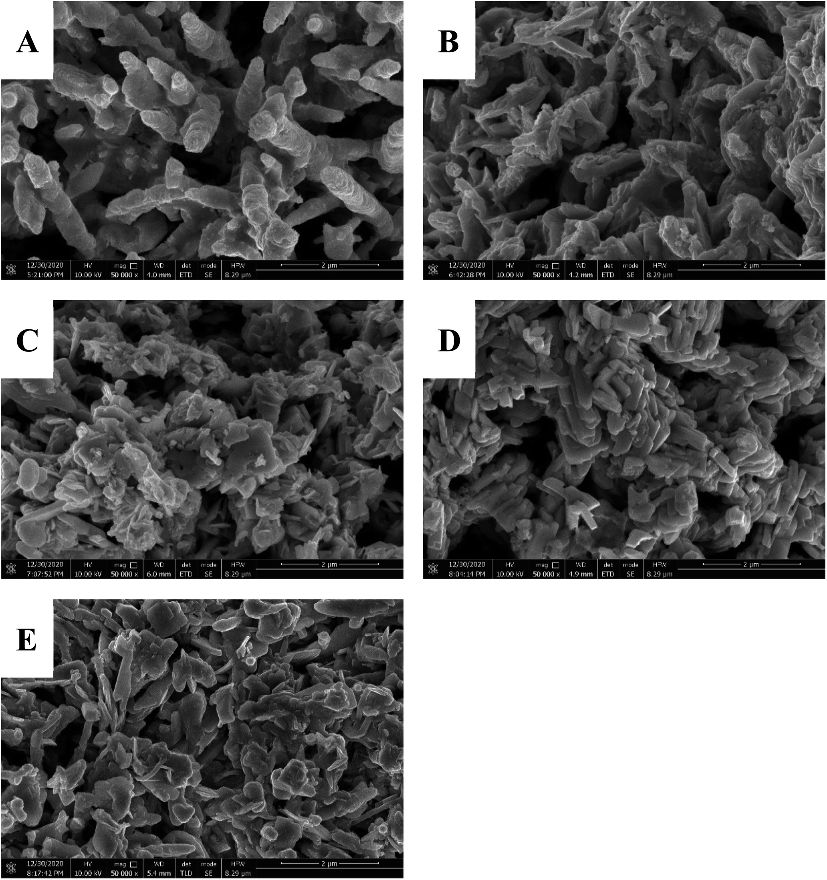 | ||
| Fig. 4 SEM images of NAMs collected from the interior of the formed negative plates: P000 (A), P050 (B), P075 (C), P100 (D) and P125 (E). (Magnification: 50000×). | ||
3.4. Electrochemical properties of the negative plates
Fig. 5A presents the cyclic voltammograms (CVs) of the negative plates in H2SO4 (1.28 g cm−3). The CVs were recorded in a three-electrode cell with a commercial positive plate as the counter electrode and a Hg/Hg2SO4 electrode as the reference electrode. Due to the large size of plates (45 mm × 26 mm), the potential scanning rate was set at 1 mV s−1. It was observed that if the potential scanning rate was greater than 1 mV s−1, the temperature of the cell was increased sharply even after one scanning cycle, leading to the accumulation of H2SO4 on the steel clips connected to the Pb plates. The yellow line is the CV of P000, on which a pair of redox peaks can be observed, which is corresponding to the electrochemical reaction between Pb and PbSO4. After incorporation of 50 ppm of a-MWCNTs, the morphology of the NAMs turns from the intercrossed Pb rods into the piled Pb plates, resulting in a decrease in the porosity of the material. On the CV, the positive shift of the oxidation peak potential and the decrease of the oxidation peak current both suggest that the electrochemical redox reactions are retarded (blue line). However, when the content of a-MWCNTs in negative lead paste is increased to 75 ppm, the material is comprised of agglomerates consisted of Pb slices, resulting in the increase in both the porosity and active surface area. The electrochemical transformation between Pb and PbSO4 is accelerated, leading to the increase of oxidation peak current and negative shift of reduction peak potential (blue line). When the content of a-MWCNTs in negative lead paste reaches to 100 ppm, the NAMs is composed of interconnected domino-like Pb slices, The redox peak currents on CV are greatly increased because of the promoted electrochemical redox reaction (red line). However, the incorporation of 125 ppm a-MWCNTs causes the decrease in the redox peak currents, which can be attributed the increased electron transfer resistance originated from the gaps in NAMs.The currents at −1.5 V can be used to evaluated the hydrogen evolution behaviors of the negative plates. Hydrogen generation is an issue greatly hindering the application of carbon materials in LAB. Similar to other carbon additives, CNTs can also lower the overpotential of hydrogen evolution reaction and promote hydrogen generation. In our previous study, we have successfully improved the HRPSoC cycle-life of LAB through incorporating 2 ppm of graphene oxide nanosheets (GONs) into conventional negative lead paste. The HRPSoC cycle-life of the simulated cell was greatly improved, while the hydrogen generation did not have any change because the content of GONs in NAMs was insignificant. However, in this work, it is found that the introduction of a-MWCNTs into negative lead paste can promote hydrogen evolution reaction, which might be ascribed to the much higher content of a-MWCNTs in the NAMs.
The charge transfer resistance (Rct) of NAMs is investigated by EIS. Fig. 5B displays the Nyquist plots of the formed negative plates, which were recorded in H2SO4 at open circuit voltage (OCV). All the plots show a feature of semicircle in the high frequency region and a straight line in the low frequency region. The diameter of the semicircle corresponds to the Rct of the negative plate. As seen, compared to other plates, P100 has the smallest Rct, which can be attributed to P100, which is comprised of the intercrossed quasi-rod Pb slices.
 | ||
| Fig. 5 Cyclic voltammograms (CVs) (A) and Nyquist plots (B) of the formed negative plates in H2SO4 (1.28 g cm−3). | ||
3.5. Tests of the simulated cells
The simulated cells were constructed by one negative plate and two commercial positive plates, which were separated by an AGM with the thickness of 1.5 mm. After that, cycle-set of HRPSoC was tested at 1C rate with the initial SOC of 50%. The test was stopped when the discharge voltage (Vdischarge) fell down to 1.6 V or when the charge voltage (Vcharge) rose to 2.83 V. Fig. 6 shows Vdischarge as a function of cycle number of each cell. The HRPSoC cycle-life for C000 is 21328 cycles. After addition of 50 ppm a-MWCNTs, the cycle-life of the cell decreases to 16592 cycles because the declined porosity and the active surface area of NAMs retards the electrochemical reactions between Pb and PbSO4, leading to the accumulation of PbSO4 crystals and consequently a shorter HRPSoC cycle-life. Afterwards, the further addition of a-MWCNTs reduces the size of Pb slices and induces the morphology change of the material. The cycle-life of the simulated cells are greatly improved due to the increased porosity and active surface area, which accelerates the electrochemical transformation between the redox couples. Especially, when a-MWCNTs content reaches to 100 ppm, the simulates cell achieves a cycle-life of 32010 cycles, which is more than 1.5 times greater than that of C000. Such a superior HRPSoC performance of C100 can be ascribed to the domino-like Pb slices. The interconnected quasi-rod structure promotes the electrochemical redox reaction and therefor suppress the accumulation of PbSO4 crystals.
 | ||
| Fig. 6 Discharge voltage (Vdischarge) as a function of cycle numbers under HRPSoC condition for the simulated cells constructed with different negative plates for the first HRPSoC cycle-set. | ||
Upon the HRPSoC tests were stopped, the simulated cells were subjected to the teardown analysis, and the NAMs were collected from the interior of negative plates for XRD and SEM characterizations. Fig. 7A are the XRD patterns of the materials collected from the interior of negative plates. As displayed, the materials are all composed of Pb and PbSO4 crystals. Fig. 7B depicts the percentages of Pb and PbSO4 crystals in each plate, which are estimated from the intensity ratio of the strongest diffraction peaks of the crystals. As seen, after the HPSoC test, the percentage of PbSO4 in P000 is 52.45%, which increases to 53.82% after the incorporation of 50 ppm a-MWCNTs. The PbSO4 percentage drops 18.65% after 75 ppm a-MWCNTs are incorporated, and decline to 13.29% when the a-MWCNTs content reaches to 100 ppm. The very low PbSO4 percentage in P100 is attributed to the material comprised of interconnected domino-like Pb slices, which accelerates the electrochemical reactions and hence prevents the PbSO4 crystals from accumulation.
 | ||
| Fig. 7 XRD patterns (A) and compositions (B) of the NAMs collected from the interior of negative plates after the HRPSoC cycle-set. | ||
The SEM images of the NAMs from the negative plates after HRPSoC tests are presented in Fig. 8. In SEM image of P000, large PbSO4 are surrounded by small Pb particles (Fig. 8A). However, in Fig. 8B, almost only large PbSO4 crystals can be seen, implying the relatively severe sulfation degree when 50 ppm a-MWCNTs is incorporated into NLP. Afterwards, the addition of 75 ppm a-MWCNTs decreases the size of PbSO4 crystals. In the meantime, a lot of small Pb particles are observed in the SEM image, implying a reduced sulfation degree of negative plates. When the content of a-MWCNTs improves to 100 ppm, almost no large PbSO4 crystals can be found in the SEM image, suggesting the significant suppression effect of the interconnected domino-like Pb slices on the accumulation of PbSO4 crystals. However, these quasi-rod Pb slices break into small pieces when the a-MWCNTs content reaches 125 ppm, and large PbSO4 crystals emerge in the SEM image again (Fig. 8E).
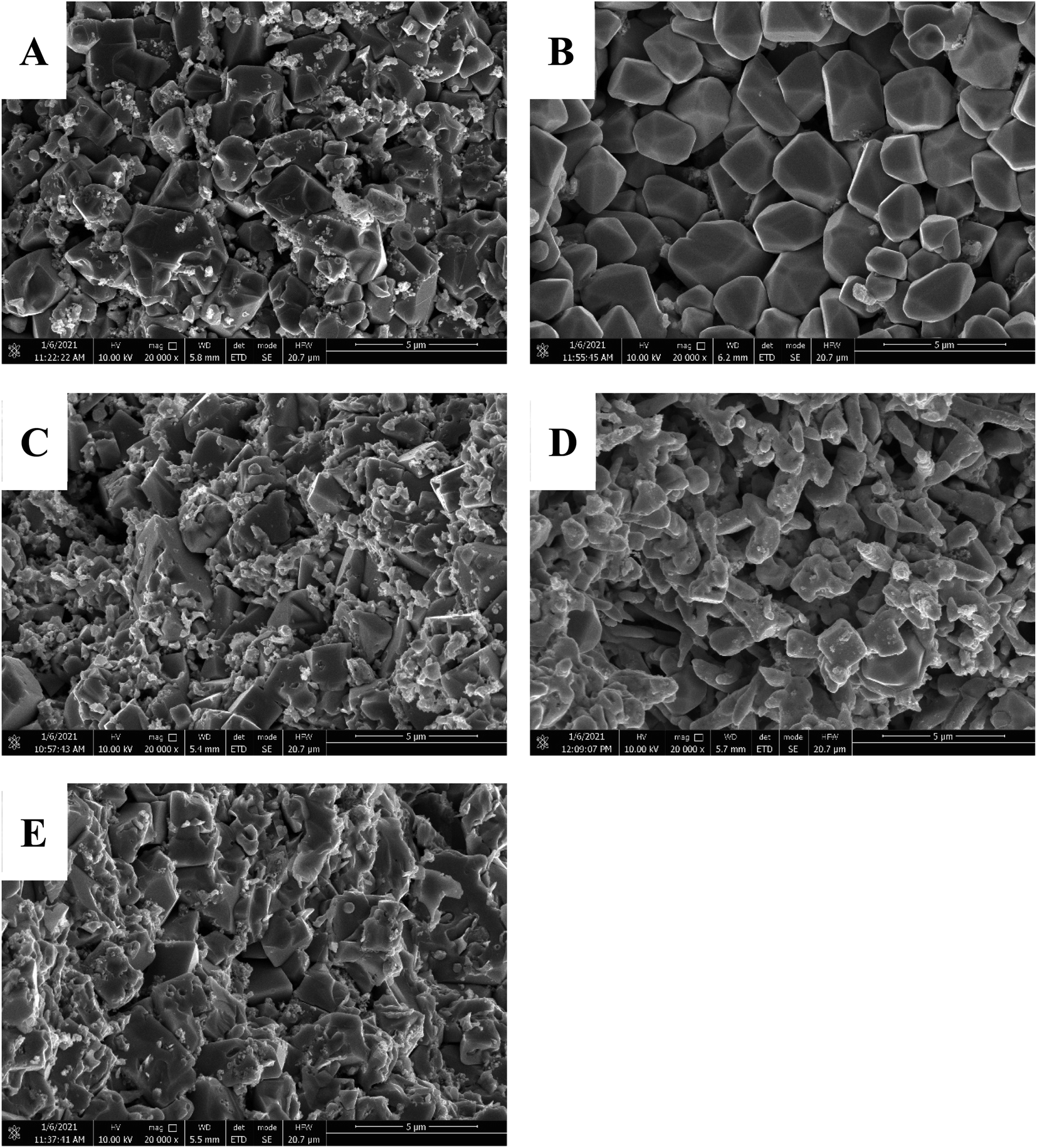 | ||
| Fig. 8 SEM images of the NAMs in the interior of the negative plates after the HRPSoC cycle-set: P000 (A), P050 (B), P075 (C), P100 (D) and P125 (E). | ||
4. Conclusion
In this work, trace amount of a-MWCNTs such as 100 ppm is incorporated into the conventional negative lead paste to improve the HRPSoC performance of LABs. It is found that the incorporation of a-MWCNTs has great effect on the chemical reactions happening during curing process, inducing the growth of domino-like Pb slices during the formation process. These quasi-rod Pb slices are interconnected, which can not only improve the porosity and surface area of the NAMs, but also provides channels for fast electron transfer. Thus, the electrochemical reaction between Pb and PbSO4 are greatly promoted, hindering the accumulation of large PbSO4 crystals and therefore suppresses the sulfation of negative plates. It is observed after incorporation of 100 ppm a-MWCNTs, the HRPSoC cycle-life of the simulated cell increases by more than 1.5 times from 21382 to 32010 cycles. Due to the convenience and low-cost, our method is believed to be able to have application in LAB industry.
Conflicts of interest
The authors declare no competing financial interest.Acknowledgements
The authors acknowledge the support of Zhaoqing Xijiang Talent Program.References
- L. Osmieri, R. K. Ahluwalia, X. Wang, H. T. Chung, X. Yin, A. J. Kropf, J. Park, D. A. Cullen, K. L. More, P. Zelenay, D. J. Myers and K. C. Neyerlin, Appl. Catal., B, 2019, 257, 117929 CrossRef CAS.
- O. J. Dada, Journal of Energy Storage, 2019, 23, 579–589 CrossRef.
- M. Saravanan, M. Ganesan and S. Ambalavanan, J. Power Sources, 2014, 251, 20–29 CrossRef CAS.
- J. Gu, J. Zhong, K. D. Zhu, X. R. Wang and S. L. Wang, Journal of Energy Storage, 2021, 33, 102082 CrossRef.
- J. Xiang, P. Ding, H. Zhang, X. Wu, J. Chen and Y. Yang, J. Power Sources, 2013, 241, 150–158 CrossRef CAS.
- R. Shapira, G. D. Nessim, T. Zimrin and D. Aurbach, Energy Environ. Sci., 2013, 6, 587–594 RSC.
- D. Pavlov, T. Rogachev, P. Nikolov and G. Petkova, J. Power Sources, 2009, 191, 58–75 CrossRef CAS.
- M. S. Rahmanifar, Electrochim. Acta, 2017, 235, 10–18 CrossRef CAS.
- P. T. Moseley, R. F. Nelson and A. F. Hollenkamp, J. Power Sources, 2006, 157, 3–10 CrossRef CAS.
- D. Pavlov, P. Nikolov and T. Rogachev, J. Power Sources, 2011, 196, 5155–5167 CrossRef CAS.
- Y. Zeng, J. Hu, W. Ye, W. Zhao, G. Zhou and Y. Guo, J. Power Sources, 2015, 286, 182–192 CrossRef CAS.
- Q. Long, G. Ma, Q. Xu, C. Ma, J. Nan, A. Li and H. Chen, J. Power Sources, 2017, 343, 188–196 CrossRef CAS.
- X. Zou, Z. Kang, D. Shu, Y. Liao, Y. Gong, C. He, J. Hao and Y. Zhong, Electrochim. Acta, 2015, 151, 89–98 CrossRef CAS.
- M. Fernández, J. Valenciano, F. Trinidad and N. Muñoz, J. Power Sources, 2010, 195, 4458–4469 CrossRef.
- S. M. Kumar, S. Ambalavanan and S. Mayavan, RSC Adv., 2014, 4, 36517–36521 RSC.
- D. Pavlov and P. Nikolov, J. Power Sources, 2013, 242, 380–399 CrossRef CAS.
- N. Sugumaran, P. Everill, S. W. Swogger and D. P. Dubey, J. Power Sources, 2015, 279, 281–293 CrossRef CAS.
- K. Hasheminejad and A. Montazeri, Appl. Surf. Sci., 2020, 502, 144150 CrossRef.
- P. T. Moseley, D. A. J. Rand and B. Monahov, J. Power Sources, 2012, 219, 75–79 CrossRef CAS.
- G. Petkova, P. Nikolov and D. Pavlov, J. Power Sources, 2006, 158, 841–845 CrossRef CAS.
- L. Bai, Y. Zhang, W. Tong, L. Sun, H. Huang, Q. An, N. Tian and P. K. Chu, Electrochem. Energy Rev., 2019, 3, 395–430 CrossRef.
- C. Tang, H.-F. Wang, J.-Q. Huang, W. Qian, F. Wei, S.-Z. Qiao and Q. Zhang, Electrochem. Energy Rev., 2019, 2, 332–371 CrossRef CAS.
- Y.-J. Wang, B. Fang, D. Zhang, A. Li, D. P. Wilkinson, A. Ignaszak, L. Zhang and J. Zhang, Electrochem. Energy Rev., 2018, 1, 1–34 CrossRef CAS.
- P. E. Lokhande, U. S. Chavan and A. Pandey, Electrochem. Energy Rev., 2019, 3, 155–186 CrossRef.
- J. Han, W. Wei, C. Zhang, Y. Tao, W. Lv, G. Ling, F. Kang and Q.-H. Yang, Electrochem. Energy Rev., 2018, 1, 139–168 CrossRef CAS.
- J. Pan, Y. Sun, W. Li, J. Knight and A. Manthiram, Nat. Commun., 2013, 4, 2178 CrossRef PubMed.
- S. W. Swogger, P. Everill, D. P. Dubey and N. Sugumaran, J. Power Sources, 2014, 261, 55–63 CrossRef CAS.
- A. Banerjee, B. Ziv, Y. Shilina, E. Levi, S. Luski and D. Aurbach, ACS Appl. Mater. Interfaces, 2017, 9, 3634–3643 CrossRef CAS PubMed.
- A. Banerjee, B. Ziv, E. Levi, Y. Shilina, S. Luski and D. Aurbach, J. Electrochem. Soc., 2016, 163, A1518–A1526 CrossRef CAS.
- S. Logeshkumar and R. Manoharan, Electrochim. Acta, 2014, 144, 147–153 CrossRef CAS.
- R. Marom, B. Ziv, A. Banerjee, B. Cahana, S. Luski and D. Aurbach, J. Power Sources, 2015, 296, 78–85 CrossRef CAS.
- M. Saravanan, P. Sennu, M. Ganesan and S. Ambalavanan, J. Electrochem. Soc., 2012, 160, A70–A76 CrossRef.
- S. Mithin Kumar, S. Arun and S. Mayavan, Journal of Energy Storage, 2019, 24, 100806 CrossRef.
- J. Wang, L. Dong, M. Liu, J. Wang, Q. Shao, A. Li, W. Yan, J. C.-Y. Jung and J. Zhang, Journal of Energy Storage, 2020, 29, 101325 CrossRef.
- J. Zhang, H. Zou, Q. Qing, Y. Yang, Q. Li, Z. Liu, X. Guo and Z. Du, J. Phys. Chem. B, 2003, 107, 3712–3718 CrossRef CAS.
- S. L. H. Rebelo, A. Guedes, M. E. Szefczyk, A. M. Pereira, J. P. Araújo and C. Freire, Phys. Chem. Chem. Phys., 2016, 18, 12784–12796 RSC.
- T. L. do Amaral Montanheiro, F. H. Cristóvan, J. P. B. Machado, D. B. Tada, N. Durán and A. P. Lemes, J. Mater. Res., 2015, 30, 55–65 CrossRef.
- P. Baishya and T. K. Maji, Carbohydr. Polym., 2016, 149, 332–339 CrossRef CAS.
- J. Wang, L. Dong, M. Liu, J. Wang, Q. Shao, A. Li, W. Yan, J. C.-Y. Jung and J. Zhang, Journal of Energy Storage, 2020, 29, 101325 CrossRef.
Footnote |
| † Electronic supplementary information (ESI) available. See DOI: 10.1039/d1ra02208c |
| This journal is © The Royal Society of Chemistry 2021 |