 Open Access Article
A high-efficiency oxygen evolution electrode material of a carbon material containing a NiCo bimetal†
Hongxin Guana,
Na Wangb,
Xuanxuan Fengb,
Shaokang Bianb,
Wei Li*a and
Yan Chen *b
*b
aState Key Laboratory of Metastable Materials Science and Technology, Yanshan University, 066004 Qinhuangdao, PR China. E-mail: liwei@ysu.edu.cn
bHebei Key Laboratory of Applied Chemistry, College of Environmental and Chemical Engineering, Yanshan University, Qinhuangdao, Hebei 066004, China. E-mail: chenyan@ysu.edu.cn
First published on 4th May 2021
Abstract
The preparation of highly efficient, stable, and low-cost electrocatalysts for the oxygen evolution reaction (OER) and the hydrogen evolution reaction (HER) is still a challenge for the development of new energy systems. In this work, a NiCo bimetal loaded on porous carbon (NiCo-C/NF) grown on nickel foam (NF) was obtained via the pyrolysis of a NiCo bimetal MOF (NiCo-MOF/NF) under a nitrogen atmosphere at 500 °C. Compared with NiCo-MOF/NF, NiCo-C/NF had a larger specific surface and uniform mesoporous structure. As an electrocatalyst in the OER, this new type of electrode operated with better stability in an alkaline solution (1.0 mol L−1 KOH), the overpotential when the current density reached 10 mA cm−2 was only 260 mV, and the electrode also exhibited long-term durability in a stability test for 10 h without significant changes. The excellent activity and stability toward the OER can be attributed to the synergistic effect of the NiCo bimetal and the abundant active sites exposed after the carbonization of NiCo-MOF, which compensated for the defect of the insufficient conductivity of the material and promoted the evolution of oxygen in the catalytic process.
1. Introduction
Increasing energy demands have stimulated a great interest in alternative energy conversion and storage systems. Environment friendly characteristics and a high calorific value of hydrogen energy is currently the primary choice for replacing traditional energy sources.1 The development of hydrogen energy, generally using water electrolysis devices and fuel cells, is all related to the oxygen evolution reaction (OER).2 Among the oxygen electrocatalysts that have been developed, platinum group metals (PGMs),3–5 such as palladium, iridium and ruthenium (for OER), had considerable catalytic activity, but a high cost and poor stability under continuous working conditions restricted their use in industrial applications.6 Therefore, it is of great importance to develop low-cost electrocatalysts with an electrocatalytic performance that is comparable to PGMs. Recently, many new OER electrocatalysts had been designed and reported, including heteroatom-doped carbon materials,7,8 transition metal compounds,9,10 transition metal carbon material composites,11–13 metal–organic frameworks (MOF) materials,14 polymers and so on.15The MOFs are a new type of material formed by the coordination of metal central ions and organic ligands.16 Because of the characteristics of high porosity, large surface area, uniform and adjustable pore size, controllable microscopic morphology and easy preparation, MOFs have been valued by more and more scientific researchers.17–20 However, there were some shortcomings when MOFs were employed in a water electrolysis catalyst.21 For example, the metal ions around the organic framework may be masked, to restrain the OER performance of the material, and the unique framework structure of the MOF material gradually changes with the progress of catalysis, and this gradually reduces the stability of the material.22–24 Researchers have made various improvements to MOF to promote catalytic performance, for example, Liu et al.25 obtained Ni3S2 nanoparticle materials supported on graphite nanosheets by calcined sulfur-containing Ni-MOF. The research showed that graphene and MOF had a catalytic synergy, and good catalytic activity. At 10 mA cm−2, the overpotential of OER was 284.7 mV. Gao et al.26 successfully prepared tungsten carbide supported on cobalt. The carbon nanotube porous material had an OER overpotential of 323 mV at 10 mA cm−2, and the material also had stable electrocatalytic activity. Once the MOF material was treated by pyrolysis or other methods, the original problem of insufficient conductivity of the MOF was improved.27–29 Due to the synergistic effect of the reduced metal particles and the pyrolytic graphite carbon framework, the number of active sites of the catalyst material was increased,30 and the carbon framework supported the catalyst, so that the catalyst morphology was improved, and there was no significant change before and after catalysis.31
Based on this strategy, a solvothermal method shown in Scheme 1 was used to grow a NiCo bimetal containing MOF on the surface of NF (NiCo-MOF/NF) as a precursor, and then this was used to successfully synthesize a NiCo bimetallic carbon material (NiCo-C/NF) using calcination and pyrolysis. The organic framework in the MOF was decomposed in situ into the conductive carbon framework and this maintained its intrinsic structure during high temperature treatment. The support of the carbon framework improved the stability of the catalyst, and the exposed metal particles provided more catalytically active sites. At the same time, the synergy of the carbon framework and the metal particles also improved the overall catalytic effect of the catalyst. In addition, the pyrolysis method increased the distance between the nanosheet material, and its unique morphology also made it difficult for it to collapse during the catalytic process. Hence, as an electrode catalyst used directly for the electrolysis of water, NiCo-C/NF displayed excellent OER performance and stability in alkaline solution.
2. Experimental section
2.1 Fabrication of NF-based electrodes
Nickel foam (NF) was washed with dilute hydrochloric acid (HCl, 1 M) solution and acetone for 15 min with an ultrasonic cleaner to remove the oxide layer and organics on the surface. Then after washing with water, the NF was dried in a vacuum drying oven at 60 °C for 1 h, and finally cut into a 10 mm × 50 mm × 1 mm for use later.Nickel nitrate hexahydrate (Ni(NO3)2·6H2O, 0.96 mM), cobalt nitrate hexahydrate (Co(NO3)2·6H2O, 0.96 mM), and terephthalic acid (TPA, C8H6O4, 0.96) mM) were dissolved in 25 ml of a mixed solution of N,N-dimethyl formamide (DMF), ethanol and water with a volume ratio of 23![[thin space (1/6-em)]](https://www.rsc.org/images/entities/char_2009.gif) :
:![[thin space (1/6-em)]](https://www.rsc.org/images/entities/char_2009.gif) 1
1![[thin space (1/6-em)]](https://www.rsc.org/images/entities/char_2009.gif) :
:![[thin space (1/6-em)]](https://www.rsc.org/images/entities/char_2009.gif) 1, and a magnetic rotor was used to thoroughly stir the mixture for 30 min, and then the completely mixed solution was transferred to a 50 ml Teflon lined high pressure autoclave. Next the cleaned, dry NF was immersed into the mixture in the Teflon lined, high pressure autoclave and annealed in a muffle furnace at 125 °C for 12 h. After cooling down the furnace to room temperature, the NiCo-MOF/NF was taken out and washed three times with pure water and anhydrous ethanol alternately, and then placed in a 60 °C oven to dry overnight before further processing. The dried NiCo-MOF/NF sample was put into a tube furnace and then calcined at 500 °C for 5 h at a heating rate of 5 °C min−1 in a nitrogen atmosphere, and labeled as NiCo-C/NF.
1, and a magnetic rotor was used to thoroughly stir the mixture for 30 min, and then the completely mixed solution was transferred to a 50 ml Teflon lined high pressure autoclave. Next the cleaned, dry NF was immersed into the mixture in the Teflon lined, high pressure autoclave and annealed in a muffle furnace at 125 °C for 12 h. After cooling down the furnace to room temperature, the NiCo-MOF/NF was taken out and washed three times with pure water and anhydrous ethanol alternately, and then placed in a 60 °C oven to dry overnight before further processing. The dried NiCo-MOF/NF sample was put into a tube furnace and then calcined at 500 °C for 5 h at a heating rate of 5 °C min−1 in a nitrogen atmosphere, and labeled as NiCo-C/NF.
The same synthesis process and dosage as those used for Ni-MOF/C, were then used to obtain Co-MOF/C which was used for comparison.
2.2 Electrochemical measurements
The electrochemical measurements were carried out a CHI 660E electrochemical station (Shanghai Chenhua, China), using a three-electrode system for testing, and the electrolyte was 1.0 mol L−1 KOH solution. In all the electrochemical tests, the counter electrode and reference electrode were platinum (10 mm × 10 mm) and Hg/HgO electrodes, respectively, and the working electrode was the processed NF electrode, cut to 10 mm × 10 mm × 1 mm and used directly in the OER test without further processing. The parameter set during the cyclic voltammetry (CV) activation was the non-Faraday region of the electrode material. After the activation was completed, the electrochemical tests were carried out. The current density was normalized by the geometric area. In order to ensure the accuracy of the experiment, all the data used were 90% iR compensated, and the potential was calibrated to the reversible hydrogen electrode (RHE) using the formula ERHE = EHg/HgO + 0.059pH + 0.098. Before the linear sweep voltammetry (LSV) tests, 20 CV scan cycles were made in advance to reach a steady state. The tested rate of CV and LSV was 1 mV s−1 at room temperature and the OER test potential ranged from 0 V to 1.2 V (vs. Hg/HgO). Electrochemical impedance spectroscopy (EIS) was carried out from 100 kHz to 0.01 Hz with an AC voltage amplitude of 5 mV. The formula for obtaining the overpotential was η = ERHE − 1.23. The electrochemical active surface area (ECSA) was determined by measuring the double-layer capacitance (Cdl) on the catalyst surface. The Cdl was determined by measuring the CV in the area of a non-faradaic potential. The voltage range of the CV curve for different sweep speeds was −0.1–0 V (vs. Hg/HgO), and the sweep speeds were 10–120 mV s−1. The electric double-layer capacitance of the electrode could be obtained from the relationship between current and sweep speed: dj = Cdl/dv. This assumes that both Ni and Co ions are active substances. The turnover frequency (TOF) was obtained by formula: TOF = jA/(4Fn), where j is the current density at a given potential (A cm−2), A is the geometric area of the electrode (cm2), the number 4 is the transfer of 4 electrons in the OER, F is the Faraday constant (96![[thin space (1/6-em)]](https://www.rsc.org/images/entities/char_2009.gif) 485 C mol−1), and n is the total number of moles (mol) of the Co and Ni sites in the active material. The Tafel slope was calculated by the Tafel equation: η = b
485 C mol−1), and n is the total number of moles (mol) of the Co and Ni sites in the active material. The Tafel slope was calculated by the Tafel equation: η = b![[thin space (1/6-em)]](https://www.rsc.org/images/entities/char_2009.gif) log
log![[thin space (1/6-em)]](https://www.rsc.org/images/entities/char_2009.gif) j + a, and the LSV curve data was used. In the Tafel equation, η represents the overpotential, j represents the current density, b is the Tafel slope, and a is the Tafel constant. The i–t curve was tested at a voltage of 1.70 V (vs. RHE) for 10 h.
j + a, and the LSV curve data was used. In the Tafel equation, η represents the overpotential, j represents the current density, b is the Tafel slope, and a is the Tafel constant. The i–t curve was tested at a voltage of 1.70 V (vs. RHE) for 10 h.
3. Results and discussion
3.1 Morphology and structure characterization
The crystallography structure and phase information of the as-prepared MOF samples were investigated using X-ray diffraction (XRD) and the results are shown in Fig. 1a. The XRD data revealed the typical diffraction peaks for the (200), (001), (201), and (400) planes of the MOFs, which confirmed the successful synthesis of the Ni-MOF precursor templates (CCDC No. 985792).32 After high temperature treatment (Fig. 1b), a broad peak appeared at 20°–40°, which was determined as a diffraction signal of amorphous carbon. This showed that the MOFs were carbonized to form a carbon framework after calcination. Simultaneously, standard peaks of Ni (PDF#04-0850) and Co (PDF#15-0806) metals appeared, and this showed that the MOFs produced Ni and Co metals after high temperature treatment. The weak and broad peak suggested that the Ni and Co metals were distributed on the as-formed products as a small sized feature, and a low crystallization property, respectively. The thermogravimetric (TG) results in Fig. S5 (ESI†) showed that the organic framework in the MOF began to decompose into carbon materials at about 400 °C, and the results of the TG also proved that the organic framework had been pyrolyzed into a carbon framework.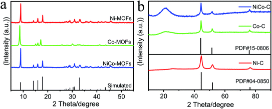 | ||
| Fig. 1 (a) Experimental and simulated XRD patterns of MOFs. (b) The XRD patterns of MOFs calcined at high temperatures. | ||
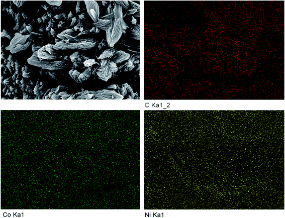
The SEM comparison of NiCo-MOF/NF before and after high temperature treatment is shown in Fig. 2. After the Ni-MOF/NF underwent high temperature treatment, the original nano flakes all collapsed and agglomerated due to the loose flake structure. However, this phenomenon did not occur after Co-MOF/NF and NiCo-MOF/NF were calcined. The tighter morphology and structure of Co-MOF and NiCo-MOF supported each other and suppressed the occurrence of the agglomeration process, during the calcination process, so that their original morphology was almost maintained. At the same time, due to the overflow of organic ligands, the material had a porous structure, which was more favorable to the adsorption of catalyzed substrate water molecules and the escape of the generated oxygen. The distance between the layers of the nanosheets was significantly increased, and small particles appeared between the layers. Edges of NiCo-MOF/NF calcined at high temperature also had different degrees of curling, and there were curled small pieces and small particles on the flakes. It was obvious from the EDS results shown in Fig. 3 that the C, Ni, and Co elements were uniformly distributed. Combining these results with the results of XRD analysis, it could be inferred that after high temperature calcination, the NiCo metal ions, as the main structure, combined to form the crystal structure of the MOFs with terephthalic acid (TPA) organic ligands. Because of the calcination, the organic framework was pyrolyzed into a carbon–carbon framework, and the metal ions were reduced to metal particles supported by the carbon framework, and the organic components in the MOF were decomposed in situ to form a stable carbon framework, whereas the metal ions were transformed into metal particles embedded in the conductive carbon framework, and the gap between the layers was enlarged to facilitate gas escape.
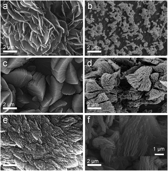 | ||
| Fig. 2 SEM images of (a) Ni-MOF/NF, (b) Ni-C/NF, (c) Co-MOF/NF, (d) CoC/NF, (e) NiCo-MOF/NF, and (f) NiCo-C/NF. | ||
Moreover, the nitrogen adsorption–desorption tests were carried out to investigate the porosity of the samples. The NiCo-MOF/NF material displayed a BET surface area of 40.0982 m2 g−1 and is shown in Fig. 4, and the BET surface area of NiCo-C/NF after high temperature treatment was 93.0493 m2 g−1, which showed that the specific surface area had increased significantly. The pore size had also been increased from 3.78 nm to 16.22 nm (Fig. 4b). The increase in specific surface area and larger pore-size provided a good environment for an OER with a good adsorption solution and desorption gas, which was conducted to effect mass transfer between the electrocatalyst and the electrolyte.
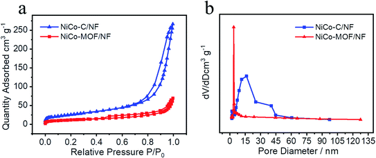 | ||
| Fig. 4 (a) Nitrogen adsorption–desorption isotherms and (b) pore-size distributions of NiCo-C/NF and NiCo-MOFs/NF. | ||
3.2 Electrochemical characterization
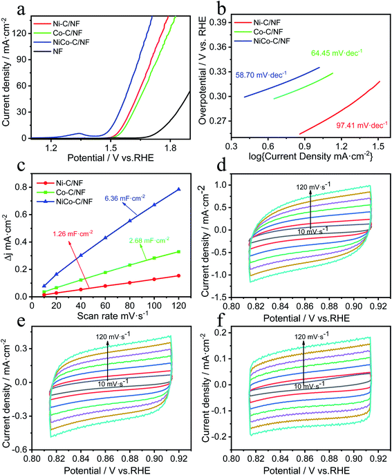
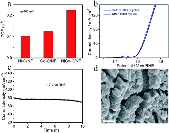
A three-electrode system was used for the electrocatalysis testing which was carried out in 1.0 mol L−1 KOH electrolyte. For comparison, in addition to NiCo-C/NF, the OER performance of Ni-C/NF, Co-C/NF and MOFs without high temperature carbonization were also tested and the results are shown in Fig. 5a. The overpotential of NiCo-C/NF at 10 mA cm−2 was 260 mV, which showed there was excellent OER activity, and its performance was better than those of Ni-C/NF (320 mV, 10 mA cm−2), Co-C/NF (340 mV, 10 mA cm−2) and NF (523 mV, 10 mA cm−2). When compared with the OER performance before carbonization (Fig. S2a, ESI†), the OER performances of the specimens were improved overall after high-temperature calcination and carbonization, and in particular, the OER overpotential of NiCo-C/NF increased by 110 mV. The Tafel slope of NiCo-C/NF shown in Fig. 5b was 58.70 mV dec−1, which was lower than that of other prepared catalyst materials. The lower Tafel slope indicated that the NiCoC/NF had a higher charge transfer ability. The Cdl was obtained by measuring CVs at different scan rates to obtain ECSA (Fig. 5c), and Fig. 5e and f show the NiCo-C/NF, Ni-C/NF and Co-C/NF CVs measured at different scan rates (10–120 mV s−1). As shown in Fig. 5c, the Cdl of NiCo-C/NF was 6.36 mF cm−2, which was larger than the Cdl of the other catalysts, indicating that NiCo-C/NF had the highest ECSA. The TOF was also one of the important indicators used for comparing the intrinsic activity of the catalyst. The TOFs of the catalysts were measured and calculated using an overpotential of 400 mV. As shown in Fig. 6a, the TOF of NiCo-C/NF was 0.225 s−1, which was significantly higher than those of Ni-C/NF (0.102 s−1), Co-C/NF (0.127 s−1) and other MOFs (shown in Fig. S3, ESI†) NiCo-MOF/NF was 0.052 s−1, Ni-MOFs/NF was 0.015 s−1 and Co-MOFs/NF was 0.010 s−1. Fig. 6c shows the stability testing results for the catalyst, which passed the 10 h i–t test to evaluate the practicability of using the catalyst. At a constant voltage, E = 1.7 V (vs. RHE), the current density had no obvious downward trend. In addition, compared with the first LSV curve (Fig. 6b), there was no significant difference in the LSV after 1000 CV cycles. Fig. 6d shows that the morphology of the catalyst still almost maintained its original structural morphology after the carbonization treatment. The untreated MOFs (Fig. S4, ESI†) had various degrees of collapse and agglomeration after testing. The results showed that it was difficult to disintegrate the unique porous carbon material, produced by the MOF after high temperature calcination in the absence of air, during the catalytic process. At the same time, the uniform mesopores facilitated the adsorption of water molecules and this avoided the collapse of the morphology during the desorption process from the catalyst electrode when oxygen was generated. To investigate the kinetics of the interface between the electrode material and the electrolyte at the OER process, EIS measurements was carried out in a 1 M KOH solution at the overpotential corresponding to the current density of 20 mA cm−2. The charge transfer resistance (Rct) was mainly determined by measuring the diameter of the semicircle in the Nyquist plots. It could be seen intuitively from Fig. S6 (ESI†) that the Rct of the catalyst after high-temperature pyrolysis and carbonization was smaller than that of the catalyst before pyrolysis and carbonization, and NiCo-C/NF had the smallest Rct. This showed that the prepared NiCo-C/NF had fast electron transfer.The great improvement of the OER electrocatalytic performance of NiCo-MOF/NF after carbonization treatment may be attributed to the unique morphology and effective bimetal modification after high temperature treatment. In particular, the highly dispersed architecture exposed more active sites, promoted the charge transfer, and increased contact with the electrolyte. Moreover, the high specific surface area and porosity may be more beneficial to the release of gas, because the gas will not damage the overall structure of the material if the gas escapes under the support of the carbon skeleton. The in situ growth on the NF also enhanced the conductivity of the material and the active sites will not be covered by the binder, and more active centers can be provided.33 In addition, the in situ growth of the NiCo-C/NF can further increase charge transfer and conductivity.34,35 The synergy between the amorphous carbon and the NiCo alloy particles in NiCo-C/NF sufficiently improved the catalytic performance.
4. Conclusions
Using a simple solvothermal method and high-temperature pyrolysis method, an efficient and durable NiCo bimetal carbon material OER electrocatalyst was grown in situ on nickel foam. The catalyst had an ultra-low overpotential of 260 mV at a current density of 10 mA cm−2, and the Tafel slope was very small (58.70 mV dec−1). The i–t curve showed excellent long-term durability at 1.70 V, and the structure showed no significant aggregation after 1000 CV cycles. This simple method can be further extended to synthesize other electrocatalyst materials with excellent electrical properties.Conflicts of interest
There are no conflicts to declare.Acknowledgements
This research did not receive any specific grants from funding agencies in the public, commercial, or not-for-profit sectors.References
- Z. . Chen, A. Yu, D. Higgins, H. Li, H. J. Wang and Z. W. Chen, Nano Lett., 2012, 12, 1946–1952 CrossRef CAS PubMed.
- D. U. Lee, P. Xu, Z. P. Cano, A. G. Kashkooli, M. G. Park and Z. W. Chen, J. Mater. Chem. A, 2016, 4, 7107–7134 RSC.
- N. Mamaca, E. Mayousse, S. Arrii-Clacens, T. W. Napporn, K. Servat, N. Guillet and K. B. Kokoh, Appl. Catal., B, 2012, 111, 376–380 CrossRef.
- S. Bordiga, C. Lamberti, G. Ricchiardi, L. Regli, F. Bonino, A. Damin, K. P. Lillerud and M. Bjorgen, Chem. Commun., 2004, 20, 2300–2301 RSC.
- S. Dang, Q. L. Zhu and Q. Xu, Nat. Rev. Mater., 2017, 1, 17075–17089 Search PubMed.
- Y. F. Lin, G. Chen, H. Wan, F. S. Chen, X. H. Liu and R. Z. Ma, Small, 2019, 15, 1900348 CrossRef PubMed.
- Y. Y. Huang, Y. Q. Wang, C. Tang, J. Wang, Q. Zhang, Y. B. Wang and J. T. Zhang, Adv. Mater., 2019, 31, 803800 Search PubMed.
- S. S. Shinde, C. H. Lee, A. Sami, D. H. Kim, S. U. Lee and J. H. Lee, ACS Nano, 2017, 17, 347–357 CrossRef PubMed.
- H. Zhang, T. T. Wang, A. Sumboja, W. J. Zang, J. P. Xie, D. Q. Gao, S. J. Pennycock, Z. L. Liu, C. Guan and J. Wang, Adv. Funct. Mater., 2018, 28, 1804846 CrossRef.
- T. Y. Ma, S. Dai, M. Jaroniec and S. Z. Qiao, J. Am. Chem. Soc., 2014, 13, 613925–613931 Search PubMed.
- G. T. Fu, Z. M. Cui, Y. F. Chen, Y. T. Li, Y. W. Tang and B. G. John, Adv. Energy Mater., 2017, 7, 1601172 CrossRef.
- S. Li, C. X. Cheng, J. Zhao, J. Schmidt and A. Thomas, Angew. Chem., Int. Ed., 2018, 57, 1856–1862 CrossRef CAS PubMed.
- Y. Jiang, Y. P. Deng, J. Fu, D. U. Lee, R. L. Liang, P. C. Zachary, Y. S. Liu, Z. Y. Bai, H. Sooyeon, L. Yang, D. Su, W. G. Chu and Z. W. Chen, Adv. Energy Mater., 2018, 8, 1702900 CrossRef.
- G. B. Chen, J. Zhang, F. X. Wang, L. L. Wang, Z. Q. Liao, E. Zschech, K. Müllen and X. L. Feng, Chemistry, 2018, 24, 18413–18418 CrossRef CAS PubMed.
- S. S. Shinde, C. H. Lee, J. Y. Yu, D. H. Kim, S. U. Lee and J. H. Lee, ACS Nano, 2018, 12, 596–608 CrossRef CAS PubMed.
- H. Y. Li, X. L. Wang, T. Wang and F. X. Xiao, A facile, J. Alloy. Compd, 2020, 844, 156224 CrossRef CAS.
- Y. Li, Y. Zhou, H. Wen, J. Yang, C. Maouche, Q. Liu, Y. Wu, C. Cheng, J. Zhu and X. Cheng, Dalton Trans., 2018, 47, 14992–15001 RSC.
- L. L. Wu, Q. S. Wang, J. Li, Y. Long, Y. Liu, S. Y. Song and H. J. Zhang, Small, 2018, 14, 1704035 CrossRef PubMed.
- R. Yang, Y. Zhou, Y. Xing, D. Li, D. Jiang, M. Chen, W. Shi and S. Yuan, Appl. Catal., B, 2019, 253, 131–139 CrossRef CAS.
- Y. Zhao, Curr. Opin. Chem. Biol., 2019, 51, 146–153 CrossRef CAS PubMed.
- M. W. Xie, Y. Ma, D. M. Lin, C. G. Xu, F. Y. Xie and W. Zeng, Nanoscale, 2020, 12, 67–71 RSC.
- Q. Zhang, H. X. Zhong, F. L. Meng, D. Bao, X. B. Zhang and X. L. Wei, Nano Res., 2018, 11, 1294–1300 CrossRef CAS.
- H. X. Guan, N. Wang, X. X. Feng, S. K. Bian, Y. Q. Liu, M. N. Ma, W. Li and Y. Chen, Int. J. Hydrog. Energy, 2020, 45, 24333–24340 CrossRef CAS.
- J. Mohammed-Ibrahim, J. Power Sources, 2020, 448, 227375 CrossRef CAS.
- Y. F. Lin, G. Chen, H. Wan, F. S. Chen, X. H. Liu and R. Z. Ma, Small, 2019, 15, 1900348 CrossRef PubMed.
- T. Zhao, J. K. Gao, J. Wu, P. P. He, Y. W. Li and J. M Yao, Energy Technol., 2019, 7, 1800969 CrossRef.
- X. Li, M. L. Fan, D. D. Wei, M. G. Li and Y. L. Wang, Electrochim. Acta, 2020, 354, 136682 CrossRef CAS.
- T. Xiao and D. X. Liu, Micropor. Mesopor. Mat., 2019, 283, 88–103 CrossRef CAS.
- B. N. Bhadra and S. H. Jhung, Nanoscal, 2018, 10, 15035–15047 RSC.
- L. Huang, G. Gao, H. Zhang, J. X. Chen, Y. X. Fang and S. J. Dong, Nano Energy, 2020, 68, 104296 CrossRef CAS.
- W. Zhang, Y. Wang, H. Zheng, R. Li, Y. J. Tang, B. Y. Li, C. Zhu, L. M. You, M. R. Gao, Z. Liu, S. H. Yu and K. Zhou, ACS Nano, 2020, 14, 1971–1981 CrossRef CAS PubMed.
- A. Mesbah, P. Rabu, R. Sibille, S. Lebègue, T. Mazet, B. Malaman and M. François, Inorg. Chem., 2014, 53, 872 CrossRef CAS PubMed.
- H. J. Xu, C. F Shan, X. X. Wu, M. Z. Sun, B. L. Huang, Y. Tang and C. H. Yan, Energy Environ. Sci., 2020, 13, 2949–2956 RSC.
- X. X. Feng, S. K. Bian, N. Wang, F. Wang, H. X. Guan, X. F. Hao, M. N. Ma, X. S. Gao and Y. Chen, J. Electrochem. Soc., 2020, 167, 106501 CrossRef CAS.
- Z. Sun and Y. Luo, Soft Matter, 2011, 7, 871–875 RSC.
Footnote |
| † Electronic supplementary information (ESI) available. See DOI: 10.1039/d1ra01997j |
| This journal is © The Royal Society of Chemistry 2021 |


