
 Open Access Article
 This Open Access Article is licensed under a Creative Commons Attribution-Non Commercial 3.0 Unported Licence
The rationality of using core–shell nanoparticles with embedded internal standards for SERS quantitative analysis based glycerol-assisted 3D hotspots platform†
Xiao-An Wangab,
Wei Shena,
Binbin Zhouac,
Daoyang Yua,
Xianghu Tang *a,
Jinhuai Liu*ab and
Xingjiu Huangab
*a,
Jinhuai Liu*ab and
Xingjiu Huangab
aEnvironmental Materials and Pollution Control Laboratory, Institute of Solid State Physics, HFIPS, Chinese Academy of Sciences, Hefei 230031, China. E-mail: tangxh2011@iim.ac.cn; jhliu@iim.ac.cn; Fax: +86-551-65591132; Fax: +86-551-65591142
bInstitute of Physical Science and Information Technology, Anhui University, Hefei 230601, China
cDepartment of Mechanical Engineering, City University of Hong Kong, Kowloon, Hong Kong, China
First published on 7th June 2021
Abstract
Surface enhanced Raman spectroscopy (SERS) is a promising sensing technique that can provide unique chemical and structural fingerprint information, but gaining reliable SERS quantitative data with high sensitivity and stability still remains a challenge. Although using a molecule as an internal standard (IS) can improve the SERS quantitative capability, the reliability and SERS measuring conditions for signal fluctuations during calibration based on IS are yet to be explored when the embedded IS molecules and target objects are located in different environments. Herein, a 3D hotspot matrix SERS platform based on Au@4-MPy@AgNPs was constructed in water with the assistance of glycerol and the dynamic signal changes from the IS, i.e. 4-Mpy, and target molecules were monitored during the process of evaporation with high sensitivity and stability. In contrast to the traditional water-dispersed drying film system, the variation trends of IS and target molecules were consistent in the glycerol-assisted liquid film protection system. Therefore, it is reasonable to calibrate the signal fluctuation by utilizing the embedded IS based on the construction strategy of a glycerol-assisted 3D hotspot platform. This work demonstrates a rational, reliable and precise SERS quantitative technique for testing analyte concentrations in practical systems and has great application prospects in the field of analytical chemistry.
Introduction
Surface enhanced Raman spectroscopy (SERS) is a highly sensitive analytical detection technique that provides unique chemical and structural information on target molecules and has achieved widespread application in the qualitative analysis of substances.1–5 Reliable and universal quantitative detection is an important condition to evaluate the maturity of an analytical technique.6,7 However, quantitative analysis for SERS is still full of challenges due to the arbitrary distribution of hotspots and poor reproducibility.8,9 Developments in nanotechnology and analytical methods are urgently needed to break through this bottle-neck and move SERS towards broader practical application10–13 and it is hoped that SERS quantitative detection14 can be eventually realized.Using a molecule as an internal standard (IS) has been proposed to surmount the above-mentioned problems and the embedded IS method can be used to improve the SERS quantitative capability.15–18 In terms of the structure of the embedded IS, first, a fixed amount of IS molecules is bound on the core and then the shell is fabricated to protect IS molecules and create core–IS–shell nanoparticles. Since there is no competitive adsorption between IS and target molecules and embedded IS molecules basically cause no interference with the system to be measured, the embedded IS method for SERS quantitative detection has become a focal point of current research on SERS quantitative analysis.19–22
Although the IS molecular layer is sandwiched between the core and the shell and would not be affected by the external environment, there are still some issues that need to be clarified. First, target molecules absorbed on the shell surface have been exposed to air and might be influenced by the outer environment. Second, we know that SERS itself is a near-field phenomenon and the SERS intensity depends primarily on highly localized near-field enhancement.23–25 From this point of view, whether the signal change trends of IS and target molecules are consistent when they are located in different environments determines the reliability and stability of IS used to calibrate the SERS signal fluctuations of target molecules. Herein, IS and target molecules are located in different outer or chemical environments in core–IS–shell nanoparticles, which spurs us to attach much importance to exploring the rationality of the embedded IS method for SERS quantitative analysis.
Meanwhile, in recent years, a 3D hotspot matrix SERS strategy has been successfully developed by our group through the solvent evaporation-induced self-assembly of Ag or Au nanoparticles (AgNPs or AuNPs) which demonstrated observable SERS signal amplification and good reproducibility.26–29 Unfortunately, the SERS signals were not stable and decayed rapidly after the water evaporated completely. To conquer this deficiency, aqueous glycerol was proposed for addition to the nanoparticle solution to alleviate the evaporation and prolong the duration of the Raman signal at the highest enhancement while protecting the nanoparticles from exposure to air.30,31 Inspired by these works and enlightened by the merits of the embedded IS strategy, it is thus highly desirable to construct a long-period glycerol-stabilized 3D hotspot matrix SERS platform to monitor the variation trends of the characteristic vibration peaks of the IS and target molecules and then investigate the rationality of using core–shell nanoparticles with embedded internal standards for SERS quantitative analysis.
Hence, in this paper, a type of core–IS–shell nanostructure with Au as the core, 4-mercaptopyridine (4-Mpy) as the embedded IS Raman probe and Ag as the shell, i.e., Au@4-Mpy@AgNPs, was fabricated. Subsequently, a 3D hotspot matrix SERS platform was constructed in water with the assistance of glycerol and was successfully used to explore the use of core–IS–shell nanoparticles for the SERS quantitative detection of target molecules. The dynamic changes in signals from the IS and target molecules in the process of evaporation were monitored by directly evaporating a drop containing an aqueous glycerol solution of Au@4-Mpy@AgNPs and analytes. The variation tendencies of the IS and the target molecules were brought into correspondence with each other versus the evaporation time. Moreover, a 3D hotspot platform with high sensitivity and stability was constructed during the evaporation process. This platform remarkably increased the SERS signal of the IS and target molecules. The possibility of Au@4-MPy@AgNPs being used for SERS quantitative detection was investigated using crystal violet (CV) as the model molecule; the relative strength corrected by IS molecules had a good linear relationship with CV concentration. The nanoparticles were also applied to the simulated quantitative detection of the antibiotic malachite green (MG) and the pesticide thiram. The quantitative analysis of these two molecules showed good linear relationships between the relative signal intensities and the target molecule concentrations through calibration via the SERS signal from IS molecules. The corresponding linear relationships could be utilized for quantitative determination of MG and thiram in a wide concentration range. Thus, it is predicted that the embedded IS method based 3D hotspot matrix SERS platform in water with the assistance of glycerol may have broad application prospects for actual quantitative detection.
Experimental
Materials and instruments
4-Mercaptopyridine (4-Mpy), chloroauric acid hydrate (HAuCl4·4H2O), malachite green (MG), thiram and glycerol were obtained from Shanghai Chemicals Company. Ascorbic acid (AA), crystal violet (CV) and silver nitrate (AgNO3) were purchased from Aladdin, China. Hexadecyltrimethylammonium chloride (CTAC) and sodium borohydride (NaBH4) were purchased from Sigma. Sodium hypochlorite solution (NaClO, available chlorine 5%) was purchased from Jiangsu Qiangsheng Functional Chemical Company. All experimental glassware was washed with aqua regia before use. All reagents are of analytical grade and used without further purification. Milli-Q deionized water (18.2 MΩ cm) was used for all preparations. The scanning electron microscopy (SEM) images were taken by an Auriga focused ion-beam scanning electron microscope (FIB-SEM). Transmission electron microscopy (TEM) and scanning transmission electron microscopy (STEM) images were obtained using a FEI Tecnai G2 F20S-TWIN. The absorption spectra were obtained using a UV-2550 spectrophotometer. X-ray photo-electron spectroscopy (XPS, ESCALAB 250, Thermo-VG Scientific, USA) was used to record the elemental information. Raman spectra were performed on a LabRAM HR800 confocal microscope Raman system (Horiba Jobin Yvon) using a He–Ne laser operating at 632.8 nm. The laser beam was focused on the sample using a 10× LMPLFLN microscope objective (numerical aperture, NA = 0.25; working distance, WD = 10.6 mm). The laser power was approximately 1 mW.Synthesis of AuNPs
CTAC-stabilized homogeneous AuNPs were synthesized according to the literature32 with a small modification. The first step is to acquire Au seeds: 200 μL of 25 mM HAuCl4 solution was added to 10 mL of 100 mM CTAC solution under stirring at room temperature. Subsequently, under vigorous stirring, 400 μL of 20 mM NaBH4 solution was quickly injected into the mixture. After several minutes, 5 mL of the above solution was taken out and added into 45 mL of 100 mM CTAC to obtain the Au seed solution. Next, 3.6 mL of Au seed solution was added to 40 mL of 25 mM CTAC, followed by the addition of 160 μL of 100 mM AA solution under stirring. After 10 min, 400 μL of 25 mM HAuCl4 was quickly injected into the mixture under vigorous stirring. Then, the mixture was left undisturbed at room temperature for at least 1 h. Finally, 50 μL of NaClO and 20 μL of 25 mM HAuCl4 were added under stirring. After standing for 12 h in a water bath at 30 °C, the resulting AuNPs were centrifuged (7000 rpm, 10 min), then redispersed in deionized water for further characterization and application.Fabrication of AuNPs@4-Mpy
250 μL of NaOH (1% w/w) solution was added into 20 mL of AuNPs under stirring. 400 μL of a 1 × 10⁻⁴ M 4-Mpy solution was added and then the mixture was put in a water bath at ∼40 °C for 4 h. After that, the AuNPs functionalized with 4-Mpy were centrifugated at 6500 rpm for 10 min before further use.Synthesis of Au@4-Mpy@AgNPs
After removing the supernatant by centrifugation (6500 rpm, 10 min), the Au@4-Mpy NPs concentrated solution was redispersed to its original volume in 50 mM CTAC. Then, 10 mL of the above solution was taken out and 100 μL NaOH (1%) was added into it under stirring followed by the addition of 0.5 mL of 2 mM AgNO3 solution. Subsequently, 0.5 mL of 10 mM AA was added under stirring. After standing for 6 h in water bath at 65 °C, the resulting Au@4-Mpy@AgNPs solution was centrifuged (6000 rpm, 10 min), then redispersed in deionized water before use. For comparison, Au@AgNPs were synthesized by the same process without IS molecules.Construction of SERS platform for quantitative analysis
After 10 mL of Au@4-Mpy@AgNPs dispersion liquid was centrifuged (6000 rpm, 10 min) and 9980 μL of the colorless supernatant was discarded, the precipitate was redispersed to 2 mL in aqueous solution with the assistance of 2.5% v/v glycerol.31 Then, centrifugation of this solution (6000 rpm, 10 min) was performed and 1980 μL of the colorless supernatant was discarded. The remaining 20 μL, which contained dark pellets, was re-dispersed under sonication and used as the SERS platform. Afterwards, 10 μL of each analyte solution sampled was mixed with 2 μL of Au@4-Mpy@AgNPs concentrated solution. Finally, a 1 μL mixture droplet was placed onto a hydrophobic silicon wafer. The laser spot was focused on the substrate surface and centered at the top point of this droplet. Time-course SERS mapping was then performed. (More details about the droplet sitting on the hydrophobic silicon wafer at different states over time can be seen in Fig. S1†). The Raman spectrometer was calibrated using a silicon wafer at 520.7 cm−1. For each SERS spectrum, baseline correction was performed using LabSpec V5.58.25 software and the peak frequency was obtained from peak fitting.Results and discussion
Synthesis, morphology, and spectral properties of Au@4-Mpy@AgNPs
Fig. 1A displays the synthesis procedure of Au@IS@AgNPs. The Au nanosphere was selected as the core, 4-Mpy as the embedded Raman probe to offer an IS signal for SERS quantitative analysis and Ag as the protective shell to support the highest possible enhancement. The Au@4-Mpy@AgNPs are clearly quasispherical and uniformly dispersed in the TEM images (Fig. 1B and C). Moreover, the color of the central region of the particles is much darker than the surrounding edges, indicating that the Au core is evenly covered with the Ag shell. The average diameter of the Au@4-Mpy@AgNPs is approximately 72 ± 6 nm, which is larger than that of the Au core (48 ± 3 nm, Fig. S2†). After the addition of 4-Mpy, the diameter distribution is basically unchanged, which illustrates that the modification of 4-Mpy had no effect on the particle size and dispersion of Au core. To further explore the spatial distribution of the Au core, embedded molecular layer and Ag shell, the element distribution of Au@4-Mpy@AgNPs was examined by STEM-EDS elemental mapping analysis. We can clearly see from Fig. 1D that the distribution contours of the three elements are basically the same, indicating that the Au, Ag and S elements are evenly distributed (the EDS spectrum can be seen in Fig. S3†). However, the circular diameter of the Au element distribution is significantly smaller than that of Ag, which is consistent with the structure of Au as the core and Ag as the shell. The circular distribution of the S element indicates that it is distributed on the whole structure and its contour range is smaller than that of Ag, showing that the internal standard molecular layer was successfully embedded in the core–shell particle. | ||
| Fig. 1 (A) Schematic illustration of the synthesis of Au@IS@AgNPs. (B and C) TEM images of the Au@4-Mpy@AgNPs. (D) STEM images of the Au@4-Mpy@AgNPs using the Ag Lα1, Au Lα1 and S Kα1 signals. (E) UV-Vis spectra of the AuNPs and Au@4-Mpy@AgNPs. (F) Raman spectra of the AuNPs and Au@4-Mpy@AgNPs. | ||
To further investigate the optical properties of the Au@4-Mpy@AgNPs, ultraviolet-visible (UV-Vis) and Raman spectroscopy characterizations were carried out. As can be clearly seen from Fig. 1E, when the core of the AuNPs was coated with a molecular layer followed by the Ag shell, the localized surface plasmon resonance peak was obviously enhanced and shifted from ∼528 nm to approximately 500 nm and a broad shoulder appeared at around 420 nm, attributed to the formation of the core–shell structure. Here, it is worth mentioning that the embedded 4-Mpy molecules could be directly used as a Raman probe to evaluate the SERS effect of Au@4-MPy@AgNPs. As shown in Fig. 1F, an intense and sharp Raman peak at 1095 cm−1 from 4-Mpy33,34 was observed and this characteristic vibration peak was very stable, which makes 4-Mpy an ideal IS for quantitative SERS analysis studies (more details can be seen in Fig. S4–S6†). Moreover, through the construction of the 3D hotspot matrix SERS platform with the glycerol-assisted liquid film protection system (i.e. the SERS platform was constructed in water with the assistance of 2.5% v/v glycerol), the enhancement factor (EF) values for Au@4-Mpy@AgNPs based on the optimal hotspots of dynamic SERS spectrum were calculated. Based on the Raman intensities of the ring breathing vibration mode at 1006 cm−1 and the trigonal ring breathing vibration mode at 1095 cm−1, the EFs for the ring and trigonal ring breathing vibration modes were calculated to be 3.5 × 10⁵ and 1.27 × 10⁶, respectively, showing the good SERS activity of this type of Au@IS@AgNPs (more details can be seen in Tables S1, S2, Fig. S7 and S8†). From this, it can be proved that the Au@4-Mpy@AgNPs are potential substrates with an IS for SERS signal fluctuation calibration research.
The XPS characterization also proved the insertion of IS molecules between the core and the shell. As shown in Fig. 2A, detailed XPS characterization was carried out for the purpose of obtaining surface composition information for the samples at each stage of the fabrication of Au@4-Mpy@AgNPs. The XPS spectra of AuNPs, Au@4-Mpy and Au@4-Mpy@AgNPs are displayed in Fig. 2A. As seen in Fig. 2B, abundant Ag appeared on the surface of the final product Au@4-Mpy@AgNPs compared with the AuNPs and AuNPs modified with 4-Mpy, indicating that the final product surface was an Ag shell35,36 with no 4-Mpy molecules. From Fig. 2C, it can be found that the binding energy of Au 4f37–39 shifted slightly after 4-Mpy modification, demonstrating that the chemical environment of Au had changed. This might be attributed to Au interacting with 4-Mpy to form an Au–S bond. Comparing the three curves in Fig. 2D, the S 2p peak at 162 eV (ref. 40 and 41) in the red line was attributed to the Au–S bond formed by SH- and the Au surface, indicating that a large number of 4-Mpy molecules were modified onto the AuNPs surface. Moreover, the S 2p peak disappeared after the formation of the core–shell structure Au–Ag composite system, proving that there were no 4-Mpy molecules on Au@4-Mpy@AgNPs surface. Combined with the preceding results of Raman spectroscopy characterization, it can be concluded that the 4-Mpy was indeed bound to the Au surface and there is no 4-Mpy on the outer surface of Au@4-Mpy@AgNPs, which further indicated that the IS molecules were embedded between the Au core and Ag shell and could be used for quantitative SERS analysis studies.
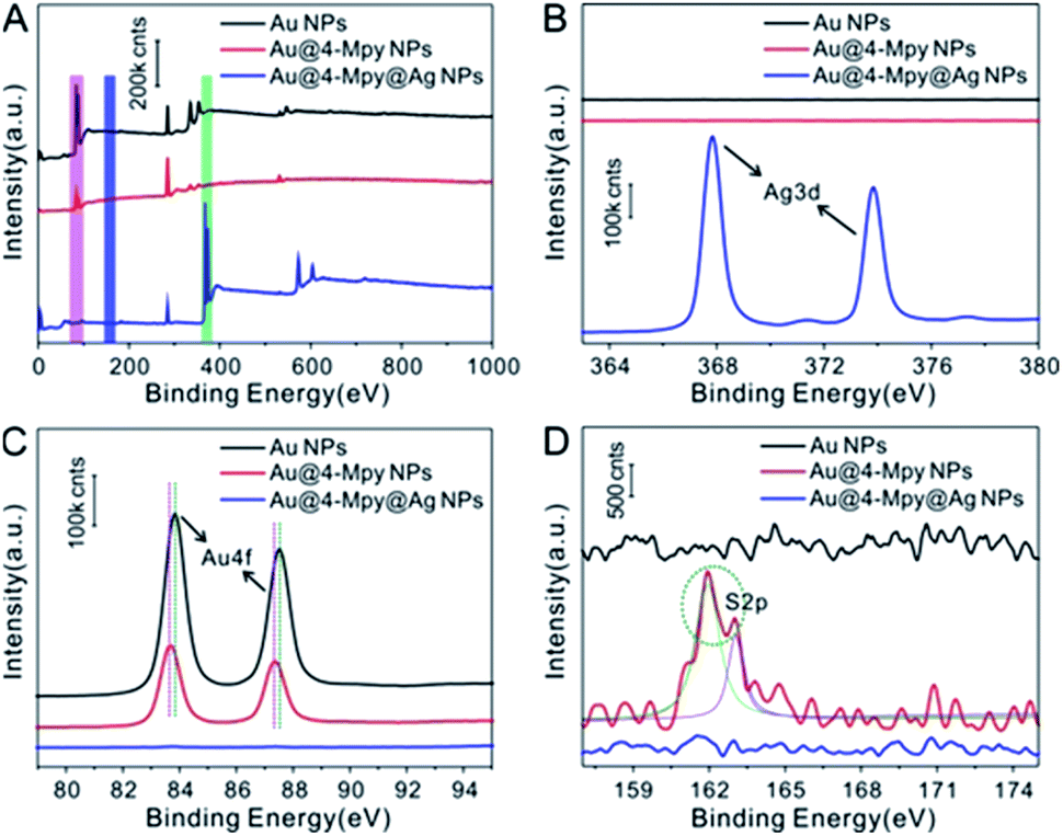 | ||
| Fig. 2 XPS characterization. (A) XPS spectra of pure Au NPs, Au NPs modified with 4-Mpy, and Au@4-Mpy@AgNPs. (B–D) The corresponding high-resolution spectra of Ag 3d (indicated by the green bar in A), Au 4f (indicated by the magenta bar in (A)) and S 2p (indicated by the blue bar in (A)). | ||
Study of the rationality of the embedded IS method for SERS quantitative analysis
Through the stark contrast of the dynamic SERS platform based Au@4-Mpy@AgNPs for quantitative analysis by the water-dispersed drying film system (i.e. the SERS platform constructed in water) with the glycerol-assisted liquid film protection system (i.e. the SERS platform constructed in water with the assistance of 2.5% v/v glycerol), it was proved that the embedded IS method is more reliable and feasible for SERS quantitative analysis, but there are certain limiting application conditions. The presence of glycerol created a moist, protective environment which acted like an outer shell and provided a flexible coating for the target molecules to narrow the difference between the environments where the target objects and the IS molecules were located. Therefore, the variation trends of the characteristic vibration peaks of the IS and target molecules in the water-dispersed drying film system and the glycerol-assisted liquid film protection system were investigated by collecting time-ordered Raman spectra throughout the whole drying process of a 1 μL droplet containing Au@4-Mpy@AgNPs and 10−7 M CV, as can be seen in Scheme 1. (More details about the SERS spectra of CV molecules and the characterization of Au@AgNPs for comparative study can be seen in Fig. S9 and S10,† respectively). | ||
| Scheme 1 (A) Schematic illustration of the dynamic SERS platform Au@4-Mpy@AgNPs for quantitative analysis. (B and E) The 3D hotspot matrix SERS platform was constructed in water ((a) the water-dispersed drying film system) or in water with the assistance of 2.5% v/v glycerol ((b) the glycerol-assisted liquid film protection system). (C and F) Schematic of the dynamic evolutions of signal intensity of IS and target molecules from (a) or (b) process, respectively, with the signal intensity plotted as a function of the evaporation time of the droplet.30,31 (D and G) Typical SERS spectra of IS and target molecules from (a) or (b) process, respectively. CV was chosen as the model target molecule. | ||
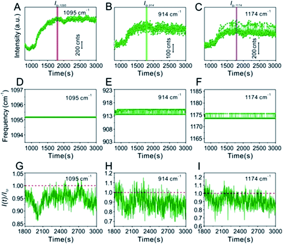
Technically, in the water-dispersed drying film system, the signal intensity trend of the IS molecules was different from that of the target molecules, as can be seen in Fig. 3. For the first ∼600 s, there was no signal for either, which was attributed to the gap distance between Au@4-Mpy@AgNPs being too large to form hotspots at the wetting stage, termed the initial state. After ∼600 s, the Raman intensity of CV increased sharply and then fell visibly (Fig. 3B and C), while the signal of the IS molecules slightly decreased and maintained high SERS enhancement, a level basically equivalent to that of the hotspots stage (Fig. 3A). The explanation for this phenomenon is as follows. With the gradual evaporation of water, at translation stages from the wetting stage to the drying stage, i.e. the final state, hotspots appeared as the nanoparticles got closer and the signal intensity increased sharply. The rapid decrease of SERS intensity can be attributed to two causes: first, when the water evaporated completely, the nanoparticles aggregated and deposited on the silicon wafer. Second, the target molecules, e.g. CV, being exposed to the laser with no protection by any apparent medium for long-time laser irradiation may cause “dissipation” of the molecules adsorbed on the outer surface of nanostructures. Meanwhile, the IS molecules were protected by the Ag shell with no direct interference from the external environment.
 | ||
| Fig. 3 (A) Time-ordered Raman spectra of the IS 4-Mpy at the 1095 cm−1 peak in the water-dispersed drying film system. The corresponding time evolution of the frequency of the (D) 1095 cm−1 peak. (G) The change of signal intensity I(t) at 1095 cm−1 after achieving optimal hotspots compared to the maximum enhancement Itp (the tipping point is indicated by the red bar in (A)). (B and C) Time-ordered Raman spectra of 10−7 M CV at 914 cm−1 and 1174 cm−1, respectively. The corresponding time evolution of the frequencies of the (E) 914 cm−1 peak and the (F) 1174 cm−1 peak. (H and I) The change of signal intensity I(t) at 914 cm−1 and 1174 cm−1 after reaching optimal hotspots compared to the maximum enhancement Itp (the corresponding tipping points are indicated by the green bar in (B) and purple bar in (C)). | ||
In contrast, in the glycerol-assisted liquid film protection system, a consistent signal change tendency between the IS and target molecules was obtained by utilizing the 3D hotspot matrix SERS platform, as shown in Fig. 4. Time courses of the characteristic peak intensities of the IS and target molecules in the glycerol-stabilized 3D hotspot SERS platform are shown in Fig. 4A–C. After the droplet containing 2.5% v/v glycerol (i.e. the initial state) was evaporated for about 1000 s, the nanoparticles begin to progress into the translation state and the highest enhancement appeared at ∼1500 s. In the next 1500 s, or until the final state, the Raman intensities fluctuated slightly and were maintained at a high level corresponding to that in the translation state. Compared to the water-dispersed drying film system, hotspots with high efficiency existed for a longer period of time in the glycerol-assisted liquid film protection system and the duration of the maximum Raman signal was prolonged for both the IS and the target molecules. This suggested that the addition of a small amount of glycerol to the Ag@4-Mpy@AgNPs could slow evaporation and avoid nanoparticle exposure to air. Here, both the IS and target molecules were protected by the media. The IS molecules were sandwiched between the Au core and the Ag shell and the target molecules were protected by the glycerol layer, which not only slowed down the disappearance of the hotspots, but also avoided the light consumption caused by direct laser irradiation. With the assistance of 2.5% v/v glycerol, the differences in the chemical environments of the IS and target molecules were reduced and the effect of electromagnetic field coupling in the hotspot matrix was more significant. Moreover, the IS and target molecules exhibited consistency under the influence of dynamic variation of electromagnetic field coupling.
 | ||
| Fig. 4 (A) Time-ordered Raman spectra of the IS 4-Mpy at the 1095 cm−1 peak in the glycerol-assisted liquid film protection system. The corresponding time evolution of the frequency of the (D) 1095 cm−1 peak. (G) The change of signal intensity I(t) at 1095 cm−1 after achieving optimal hotspots compared to the maximum enhancement Itp (the tipping point is indicated by the red bar in (A)). (B and C) Time-ordered Raman spectra of 10−7 M CV at 914 cm−1 and 1174 cm−1, respectively. The corresponding time evolution of the frequencies of the (E) 914 cm−1 peak and the (F) 1174 cm−1 peak. (H and I) The change of signal intensity I(t) at 914 cm−1 and 1174 cm−1 after reaching optimal hotspots compared to the maximum enhancement Itp (the corresponding tipping points are indicated by the green bar in (B) and purple bar in (C)). | ||
Furthermore, in the water-dispersed drying film system, the peaks of CV42–45 at 914 cm−1 and 1174 cm−1 in the SERS spectra fluctuated greatly, as shown in Fig. 3E and F. We observed more stable peak frequencies when the Ag@4-Mpy@AgNPs were in the glycerol-assisted liquid film protection system (Fig. 4E and F, respectively). Meanwhile, the peak frequencies of the IS at 1095 cm−1 remained stable almost throughout the evaporation process (Fig. 3D and 4D). In addition, in the water-dispersed drying film system, the rates of change of signal intensity of the internal and external molecules were not consistent during the state transformation. After achieving the optimal hotspots, the signal intensity of the IS decreased by about 20% compared with the maximum peak, while that of the target molecules decreased by more (Fig. 3G–I). In the glycerol-assisted liquid film protection system, the rates of change of signal intensity of the internal and external molecules tended to be the same and all fluctuated around the maximum peak (Fig. 4G–I). The above investigations of the rationality of the embedded IS method for SERS quantitative analysis indicated that it was more reasonable to calibrate the signal intensity fluctuation utilizing the IS molecules in glycerol-assisted liquid film protection system.
SERS quantitative measurements of CV analytes
Different concentrations of CV analytes were proposed as model target probes to validate the feasibility of using Au@4-Mpy@AgNPs for SERS quantitative analysis. CV molecules can be absorbed on the Ag shell surface of the Au@4-Mpy@AgNPs. Additionally, CV presents SERS signals at 914 cm−1 and 1174 cm−1 that were easily distinguished from the characteristic peak of 4-Mpy and ideal for use as a model molecule in this study. Therefore, successful SERS quantitative testing of CV with Au@4-Mpy@AgNPs was performed. In this quantitative experiment, the Raman spectra of CV solutions of various concentrations ranging from 5 × 10⁻⁷ to 5 × 10⁻⁹ M were collected by utilizing the same concentration and volume of Au@4-Mpy@AgNPs, as shown in Fig. 5A and B. The spectral peak intensities at 914 cm−1 and 1174 cm−1 of CV and the negative log of CV concentration (−log[CV]) were selected for data fitting, where the plot of I914 vs. −log[CV] plot showed the relationship between the CV peak intensity at 914 cm−1 vs. −log[CV]. From the inset of Fig. 5C, we can see that due to the interference of various factors, the I914 vs. −log[CV] plot did not present an obvious linear response nor did the I1174 vs. −log[CV] plot (inset of Fig. 5D). Fortunately, the use of the IS effectively mitigates this shortcoming. The significant progress and advantages of utilizing 4-Mpy as the IS are demonstrated in Fig. 5C and D, in which the plots of I914 and I1174 vs. −log[CV] represent the relationship between the Raman peak intensity ratio for CV (914 cm−1 or 1174 cm−1) and 4-Mpy (1095 cm−1) vs. the −log of CV concentration (−log[CV]). Compared with the I914 and I1174 vs. −log[CV] plots, the I914/I1095 and I1174/I1095 vs. −log[CV] plots displayed a relatively better linear relationship; furthermore, signals for concentrations as low as 5 × 10⁻⁹ M of CV could be readily collected. | ||
| Fig. 5 (A) Time-ordered Raman spectra of various concentrations of CV using the 3D hotspot matrix SERS platform constructed with the assistance of 2.5% v/v glycerol. (B) The SERS spectra of various concentrations corresponding to the yellow labelled part in (A). (C) Calibration plot based on the Raman intensity of I914/1095 vs. −log[CV]. The inset is a fitting plot based on Raman intensity at I914 vs. −log[CV]. (D) Calibration plot based on the Raman intensity of I1174/1095 vs. −log[CV]. The inset is a fitting plot based on Raman intensity at I1174 vs. −log[CV]. Error bars signify the RSD of 11 spectra collected continuously for 20 s after the occurrence of the optimal hotspots. | ||
The application of SERS quantitative analysis for MG and thiram analytes
SERS detection and quantitative analysis of other analytes by Au@4-Mpy@AgNPs were also performed to demonstrate the versatility and general applicability of the 3D hotspot matrix SERS platform in water with the assistance of 2.5% v/v glycerol. MG is a common antibiotic which has been widely used in the pharmaceutical and aquaculture industries as it is effective at the prevention and treatment of fungal and parasitic infections in aquacultures.46,47 However, MG has high toxicity, high residue, and carcinogenic, teratogenic and mutagenic side effects.48 Therefore, many countries have listed MG as a banned drug in aquaculture. Accurate determination of MG concentrations is crucial for regulating food safety and safeguarding human health. Therefore, it is extremely significant and challenging to develop reliable and simple methods with high sensitivity and accuracy to quantitatively determine MG.Similarly, MG analyte was quantitatively detected using the same SERS method for quantitatively measuring CV mentioned in detail above. Raman spectra were collected by mixing the concentrated Au@4-Mpy@AgNPs with different concentrations of MG containing 2.5% v/v glycerol. As can be seen from Fig. 6A, when the concentration of MG in the mixture was very low, as low as 5 × 10⁻⁹ M, the SERS signal of MG in the obtained spectra was relatively weak while the characteristic peak signal derived from the IS 4-Mpy, at 1095 cm−1, was very significant. With an increase in the concentration of MG analyte, the SERS intensity of the MG molecules at 918 cm−1, 1172 cm−1, etc.49–51 also gradually increased. Fig. 6B and D display plots of the SERS intensities at 918 cm−1 (I918) and 1172 cm−1 (I1172) versus the −log of MG concentration (−log[MG]), respectively. Plots of the relative SERS intensities at 918 cm−1 (I918/I1095) and 1172 cm−1 (I1172/I1095) versus the −log[MG] are shown in Fig. 6C and E. It can be seen that the obtained relative strength values have a good linear relationship with MG concentration between 5 × 10⁻⁹ and 5 × 10⁻⁷ M. SERS quantitative analysis of thiram pesticide residue was also carried out based on the same strategy. SERS spectra of various concentrations of thiram and the linear fitting diagram were obtained (Fig. 7). The Raman peak intensity ratio for thiram52–54 (561 cm−1 and 1386 cm−1) and 4-Mpy (1095 cm−1) displayed a relatively better linear relationship with the concentration of thiram than the I561 and I1386 vs. −log[thiram] plots. In other words, the embedded IS of Au@4-Mpy@AgNPs can be used to calibrate the signal strength of thiram, indicating that the obtained Au@4-Mpy@AgNPs can quantitatively detect thiram. The IS molecules in Au@4-Mpy@AgNPs can realize the calibration of the signal strength of the target objects, indicating that this 3D hotspot matrix SERS platform in water with the assistance of 2.5% v/v glycerol based Au@4-Mpy@AgNPs can be used for the SERS quantitative analysis of MG and thiram under certain conditions.
 | ||
| Fig. 6 (A) SERS spectra of various concentrations of MG. (B and D) Fitting plots based on Raman intensity at I918 vs. −log[MG] and I1172 vs. −log[MG], respectively. (C and E) Calibration plots based on the Raman intensity of I918/I1095 vs. −log[MG] and I1172/I1095 vs. −log[MG], respectively. Error bars signify the RSD of 11 spectra collected continuously for 20 s after the occurrence of the optimal hotspots. | ||
 | ||
| Fig. 7 (A) SERS spectra of various concentrations of thiram. (B and D) Fitting plots based on Raman intensity at I561 vs. −log[thiram] and I1386 vs. −log[thiram], respectively. (C and E) Calibration plots based on the Raman intensity of I561/I1095 vs. −log[thiram] and I1386/I1095 vs. −log[thiram], respectively. Error bars signify the RSD of 11 spectra collected continuously for 20 s after the occurrence of the optimal hotspots. | ||
Conclusions
In summary, a type of core–IS–shell nanostructure with Au as the core, 4-Mpy as the embedded IS Raman probe and Ag as the shell, i.e., Au@4-Mpy@AgNPs, was successfully fabricated and used for the construction of a 3D hotspot matrix SERS platform in water with the assistance of 2.5% v/v glycerol. By this strategy, the dynamic changes of signal from the IS, i.e. 4-Mpy, and the target molecules, such as CV analytes, were monitored during the process of evaporation with high sensitivity and stability. Experimental results revealed that, differing from the traditional water-dispersed drying film system, the variation trends of the IS and the target molecules were consistent in the glycerol-assisted liquid film protection system, which indicated that it is more reasonable to calibrate the signal fluctuation by utilizing the embedded IS based on the construction strategy of a glycerol-assisted 3D hotspot platform. From the application results of simulated SERS quantitative detection of MG and thiram, it can be found that a good linear relationship could be achieved between the relative signal intensities and the target molecule concentration through calibration via the SERS signal from the IS. The corresponding linear relationship could be utilized for quantitative determination of MG in a wide concentration range from 5 × 10⁻⁷ M to 5 × 10⁻⁹ M and of thiram from 5 × 10⁻⁶ M to 5 × 10⁻⁸ M. Thus, it is expected that the Au@4-Mpy@AgNPs based on a 3D hotspot matrix SERS platform in water with the assistance of 2.5% v/v glycerol can be used for SERS quantitative analysis under certain conditions, demonstrating a rational, reliable and precise SERS quantitative technique for testing analyte concentrations in practical systems and showing great application prospects in the field of analytical chemistry.Conflicts of interest
There are no conflicts to declare.Acknowledgements
We thank Prof. Liangbao Yang and Prof. Yulong Liu for discussions. This work was supported by the National Science Foundation of China (No. 61875206 and 61873253), the National Major Scientific and Technological Special Project for “Significant New Drugs Development” (No. 2018ZX09J18112), and the Sci-tech Police Project of Anhui Province (No. 1804d08020308).Notes and references
- S. K. Yang, X. M. Dai, B. B. Stogin and T. S. Wong, Proc. Natl. Acad. Sci. U. S. A., 2016, 113, 268–273 CrossRef CAS PubMed.
- L. Cui, D. Zhang, K. Yang, X. Zhang and Y.-G. Zhu, Anal. Chem., 2019, 91, 15345–15354 CrossRef CAS PubMed.
- H. K. Lee, Y. H. Lee, C. S. L. Koh, G. C. Phan-Quang, X. Han, C. L. Lay, H. Y. F. Sim, Y.-C. Kao, Q. An and X. Y. Ling, Chem. Soc. Rev., 2019, 48, 731–756 RSC.
- N. Akkilic, S. Geschwindner and F. Höök, Biosens. Bioelectron., 2020, 151, 111944 CrossRef CAS PubMed.
- J. Langer, D. Jimenez de Aberasturi, J. Aizpurua, R. A. Alvarez-Puebla, B. Auguié, J. J. Baumberg, G. C. Bazan, S. E. J. Bell, A. Boisen, A. G. Brolo, J. Choo, D. Cialla-May, V. Deckert, L. Fabris, K. Faulds, F. J. García de Abajo, R. Goodacre, D. Graham, A. J. Haes, C. L. Haynes, C. Huck, T. Itoh, M. Käll, J. Kneipp, N. A. Kotov, H. Kuang, E. C. Le Ru, H. K. Lee, J.-F. Li, X. Y. Ling, S. A. Maier, T. Mayerhöfer, M. Moskovits, K. Murakoshi, J.-M. Nam, S. Nie, Y. Ozaki, I. Pastoriza-Santos, J. Perez-Juste, J. Popp, A. Pucci, S. Reich, B. Ren, G. C. Schatz, T. Shegai, S. Schlücker, L.-L. Tay, K. G. Thomas, Z.-Q. Tian, R. P. Van Duyne, T. Vo-Dinh, Y. Wang, K. A. Willets, C. Xu, H. Xu, Y. Xu, Y. S. Yamamoto, B. Zhao and L. M. Liz-Marzán, ACS Nano, 2020, 14, 28–117 CrossRef CAS PubMed.
- S. E. J. Bell, G. Charron, E. Cortés, J. Kneipp, M. L. de la Chapelle, J. Langer, M. Procházka, V. Tran and S. Schlücker, Angew. Chem., Int. Ed., 2020, 59, 5454–5462 CrossRef CAS PubMed.
- M. Fan, G. F. S. Andrade and A. G. Brolo, Anal. Chim. Acta, 2020, 1097, 1–29 CrossRef CAS PubMed.
- R. Goodacre, D. Graham and K. Faulds, TrAC, Trends Anal. Chem., 2018, 102, 359–368 CrossRef CAS.
- A. I. Pérez-Jiménez, D. Lyu, Z. Lu, G. Liu and B. Ren, Chem. Sci., 2020, 11, 4563–4577 RSC.
- Y. Li, Y. Hu, F. Shi, H. Li, W. Xie and J. Chen, Angew. Chem., Int. Ed., 2019, 58, 9049–9053 CrossRef CAS PubMed.
- X. Xu, L. Zhao, Q. Xue, J. Fan, Q. Hu, C. Tang, H. Shi, B. Hu and J. Tian, Anal. Chem., 2019, 91, 7973–7979 CrossRef CAS PubMed.
- X. Zhang, D. Wu, X. Zhou, Y. Yu, J. Liu, N. Hu, H. Wang, G. Li and Y. Wu, TrAC, Trends Anal. Chem., 2019, 121, 115668 CrossRef CAS.
- Y. Fang, J.-C. Dong, S.-Y. Ding, J. Cheng, J. M. Feliu, J.-F. Li and Z.-Q. Tian, Chem. Sci., 2020, 11(5), 1425–1430 RSC.
- Q. Ding, J. Wang, X. Chen, H. Liu, Q. Li, Y. Wang and S. Yang, Nano Lett., 2020, 20, 7304–7312 CrossRef CAS PubMed.
- W. Fang, X. Zhang, Y. Chen, L. Wan, W. Huang, A. Shen and J. Hu, Anal. Chem., 2015, 87, 9217–9224 CrossRef CAS PubMed.
- W. Shen, X. Lin, C. Y. Jiang, C. Y. Li, H. X. Lin, J. T. Huang, S. Wang, G. K. Liu, X. M. Yan, Q. L. Zhong and B. Ren, Angew. Chem., Int. Ed., 2015, 54, 7308–7312 CrossRef CAS PubMed.
- S. Ma, Q. Li, Y. Yin, J. Yang and D. Liu, Small, 2017, 13, 1603340 CrossRef PubMed.
- Y. Zhao, F. Zheng, W. Ke, W. Zhang, L. Shi and H. Liu, Anal. Chem., 2019, 91, 7162–7172 CrossRef CAS PubMed.
- K. Yuan, Q. Mei, X. Guo, Y. Xu, D. Yang, B. J. Sánchez, B. Sheng, C. Liu, Z. Hu, G. Yu, H. Ma, H. Gao, C. Haisch, R. Niessner, Z. Jiang and H. Zhou, Chem. Sci., 2018, 9, 8781–8795 RSC.
- M. Li, J.-Y. Wang, Q.-Q. Chen, L.-H. Lin, P. Radjenovic, H. Zhang, S.-Y. Luo, Z.-Q. Tian and J.-F. Li, Anal. Chem., 2019, 91, 15025–15031 CrossRef CAS PubMed.
- X. Lin, Y. Wang, L. Wang, Y. Lu, J. Li, D. Lu, T. Zhou, Z. Huang, J. Huang, H. Huang, S. Qiu, R. Chen, D. Lin and S. Feng, Biosens. Bioelectron., 2019, 143, 111599 CrossRef CAS PubMed.
- Y. Xu, H. Liu and T. Jiang, J. Nano Res., 2019, 21, 107 CrossRef.
- Z. Wang, S. Zong, L. Wu, D. Zhu and Y. Cui, Chem. Rev., 2017, 117, 7910–7963 CrossRef CAS PubMed.
- X. Zhang, X. Zhang, C. Luo, Z. Liu, Y. Chen, S. Dong, C. Jiang, S. Yang, F. Wang and X. Xiao, Small, 2019, 15, 1805516 CrossRef PubMed.
- X. Wang, S.-C. Huang, S. Hu, S. Yan and B. Ren, Nat. Rev. Phys., 2020, 2, 253–271 CrossRef.
- H. Liu, Z. Yang, L. Meng, Y. Sun, J. Wang, L. Yang, J. Liu and Z. Tian, J. Am. Chem. Soc., 2014, 136, 5332–5341 CrossRef CAS PubMed.
- Y. Sun, Z. Han, H. Liu, S. He, L. Yang and J. Liu, Nanoscale, 2015, 7, 6619–6626 RSC.
- L. Yang, P. Li, H. Liu, X. Tang and J. Liu, Chem. Soc. Rev., 2015, 44, 2837–2848 RSC.
- X. Yan, P. Li, B. Zhou, X. Tang, X. Li, S. Weng, L. Yang and J. Liu, Anal. Chem., 2017, 89, 4875–4881 CrossRef CAS PubMed.
- M. Ge, P. Li, C. Cao, S. Li, D. Lin and L. Yang, Chem. Commun., 2019, 55, 8647–8650 RSC.
- Y. Wang, Z. Wei, Y. Zhang and Y. Chen, Langmuir, 2019, 35, 15795–15804 CrossRef CAS PubMed.
- C. Hanske, G. González-Rubio, C. Hamon, P. Formentín, E. Modin, A. Chuvilin, A. Guerrero-Martínez, L. F. Marsal and L. M. Liz-Marzán, J. Phys. Chem. A, 2017, 121, 10899–10906 CAS.
- X.-S. Zheng, P. Hu, J.-H. Zhong, C. Zong, X. Wang, B.-J. Liu and B. Ren, J. Phys. Chem. C, 2014, 118, 3750–3757 CrossRef CAS.
- Y. Shen, L. Liang, S. Zhang, D. Huang, J. Zhang, S. Xu, C. Liang and W. Xu, Nanoscale, 2018, 10, 1622–1630 RSC.
- Z. Zhang, J. Ahn, J. Kim, Z. Wu and D. Qin, Nanoscale, 2018, 10, 8642–8649 RSC.
- D. Li, X. Cao, Q. Zhang, X. Ren, L. Jiang, D. Li, W. Deng and H. Liu, J. Mater. Chem. A, 2019, 7, 14108–14117 RSC.
- Q. Fan, K. Liu, J. Feng, F. Wang, Z. Liu, M. Liu, Y. Yin and C. Gao, Adv. Funct. Mater., 2018, 28, 1803199 CrossRef.
- J. Hu, R. Jiang, H. Zhang, Y. Guo, J. Wang and J. Wang, Nanoscale, 2018, 10, 18473–18481 RSC.
- C. Cao, P. Li, H. Liao, J. Wang, X. Tang and L. Yang, Anal. Bioanal. Chem., 2020, 412, 4609–4617 CrossRef CAS PubMed.
- E. W. Elliott, R. D. Glover and J. E. Hutchison, ACS Nano, 2015, 9, 3050–3059 CrossRef CAS PubMed.
- F. Sun, J.-R. Ella-Menye, D. D. Galvan, T. Bai, H.-C. Hung, Y.-N. Chou, P. Zhang, S. Jiang and Q. Yu, ACS Nano, 2015, 9, 2668–2676 CrossRef CAS PubMed.
- S. L. Kleinman, E. Ringe, N. Valley, K. L. Wustholz, E. Phillips, K. A. Scheidt, G. C. Schatz and R. P. Van Duyne, J. Am. Chem. Soc., 2011, 133, 4115–4122 CrossRef CAS PubMed.
- W. Meng, F. Hu, L. Zhang, X. Jiang, L. Lu and X. Wang, J. Mol. Struct., 2013, 1035, 326–331 CrossRef CAS.
- X. Tang, W. Cai, L. Yang and J. Liu, Nanoscale, 2014, 6, 8612–8616 RSC.
- S. Lin, X. Lin, S. Han, H. Y. Zhao, W. Hasi and L. Wang, Nanotechnology, 2019, 30(21), 215601 CrossRef CAS PubMed.
- H. Tian, H. Li and Y. Fang, ACS Appl. Mater. Interfaces, 2019, 11, 16207–16213 CrossRef CAS PubMed.
- E. Ekmen, M. Bilici, E. Turan, U. Tamer and A. Zengin, Sens. Actuators, B, 2020, 325, 128787 CrossRef CAS.
- D. Pipoyan, S. Stepanyan, M. Beglaryan, S. Stepanyan and A. Mantovani, Food Chem. Toxicol., 2020, 143, 111526 CrossRef CAS PubMed.
- M. Yang, J. Yu, F. Lei, H. Zhou, Y. Wei, B. Man, C. Zhang, C. Li, J. Ren and X. Yuan, Sens. Actuators, B, 2018, 256, 268–275 CrossRef CAS.
- M. Li, B. Dyett, H. Yu, V. Bansal and X. Zhang, Small, 2019, 15, 1804683 CrossRef PubMed.
- B. Zhou, J. Shen, P. Li, M. Ge, D. Lin, Y. Y. Li, J. Lu and L. Yang, ACS Appl. Nano Mater., 2019, 2, 2752–2757 CrossRef CAS.
- X. Tang, W. Cai, L. Yang and J. Liu, Nanoscale, 2013, 5, 11193–11199 RSC.
- F. Yu, M. Su, L. Tian, H. Wang and H. Liu, Anal. Chem., 2018, 90, 5232–5238 CrossRef CAS PubMed.
- Y. Yu, P. Zeng, C. Yang, J. Gong, R. Liang, Q. Ou and S. Zhang, ACS Appl. Nano Mater., 2019, 2, 598–606 CrossRef CAS.
Footnote |
| † Electronic supplementary information (ESI) available: Fig. S1–S10, Table S1–S2. See DOI: 10.1039/d1ra01957k |
| This journal is © The Royal Society of Chemistry 2021 |