DOI:
10.1039/D1RA01795K
(Paper)
RSC Adv., 2021,
11, 15457-15466
Release of methane from nanochannels through displacement using CO2
Received
7th March 2021
, Accepted 15th April 2021
First published on 26th April 2021
Abstract
In this work, we investigate the release of methane in quartz nanochannels through the method of displacement using carbon dioxide. Molecular dynamics (MD) simulations and theoretical analysis are performed to obtain the release percentage of methane for nanochannels of various diameters. It is found that both the pressure of CO2 and the channel size affect the release percentage of methane, which increases with increasing pressure of CO2 and channel diameter. Without CO2, the majority of methane molecules are adsorbed by the channel surface. When CO2 is injected into the channel, CO2 molecules replace many methane molecules due to the relatively strong molecular interactions between CO2 and the channel, which leads to the desorption of methane, reduces the energy barrier for the transport of methane, and consequently increases the release rate. Theoretical predictions using the kinetic energy of methane and the energy barrier inside the channel are also conducted, which are in good agreement with the MD simulations.
1. Introduction
In the past decades, the rapid increase of energy consumption has posed a challenge to the growth of the worldwide economy, which has motivated the exploration of new energy sources. Among various alternatives, shale gas has become a promising source for solving the potential energy crisis.1 Compared with the traditional fossil fuels, shale gas is eco-friendly due to its low carbon emission.2,3 For the exploitation of shale gas, the combination of hydraulic fracturing and horizontal drilling is the most widely used technology for mass production.4 However, this technology consumes a large amount of water and has potential contamination of underground water.5–7 Moreover, the output of a typical shale gas well usually experiences a significant drop after three years.8,9 Therefore, it is important to find new methods to exploit shale gas.
Shale gas mainly contains methane, which is trapped in nanoscale pores of shale.10,11 The strong confinements of the nanopores make the release of shale gas a nontrivial process. In the literature, many efforts have been made to study the adsorption and desorption of methane molecules in nanopores through experiments and simulations. Rexer et al.12 examined the adsorption of methane in shale samples through experiments by varying the temperature and pressure according to various geological conditions of shale gas. They measured and modeled the methane excess uptake and isosteric enthalpy, which provide useful information for understanding the storage mechanisms of shale gas. Lithoxoos et al.13 numerically investigated the capacity of single-wall carbon nanotubes (SWCNTs) for methane storage at room temperature under different pressures and the results were confirmed by experiments. They obtained the density distributions of different gases and found that almost all the gas molecules were adsorbed by the interior surface of the pores. Zhu and Zhao14 explored the mechanisms of methane adsorption in CNTs through molecular dynamics (MD) simulations and proposed an equation of state for the adsorbed phase of methane molecules. Their equation can predict most of the adsorption phenomena observed in their simulations. Furthermore, they found that the adsorption behavior in nanopores was affected by the size and curvature of the pores. As a consequence, there exists an optimal CNT diameter that maximizes the adsorption of methane. Wu et al.15 also studied the mechanisms of methane adsorption and displacement processes in carbon nanochannels through MD simulations and obtained similar results to those of Zhu and Zhao.14 It was found that when the external pressure reaches 5 MPa, the adsorption isotherms for bulk methane is about 1.5 mmol cm−3, whereas it is about 10 mmol cm−3 in nanopores. Bartus et al.16 studied the behavior of methane molecules inside rigid and flexible carbon nanotubes (CNTs) at room temperature through classical MD simulations and obtained that the diffusion coefficient in rigid and flexible CNTs are similar. Mahdizadeh et al.17 used grand canonical Monte Carlo (GCMC) simulations to investigate the methane adsorption in single-walled carbon nanotubes (SWCNTs) and their results indicate that SWCNTs can be stylized for methane adsorption. Liu et al.18 explored the diffusion of methane at room temperature under various pressures in dry and wetted CNTs with different diameters through MD simulations. They reported that the diffusion coefficient of methane molecules reduces dramatically in wetted CNTs compared with that in dry CNTs because the low solubility of CH4, especially in thin CNTs.
In addition, there are some studies comparing the adsorption of CH4 and CO2 in nanoconfinements. Huang et al.19 used GCMC simulations to examine the adsorption behavior of an equimolar CO2/CH4 mixture in CNTs by considering the effects of pressure, temperature, and CNT diameter. They found that the adsorption of CO2 is much stronger than that of CH4 and the influences of temperature and pressure are minor in small CNTs and the CNT size affects the adsorption of CO2 more significantly than that of CH4. Lu et al.20 compared the selectivity of several nanostructures for CO2/CH4 mixtures through GCMC simulations and found that CNTs have the highest selectivity. Liu et al.21 reported a comparison of the adsorption of CO2/CH4 mixtures of three different types of carbon nanopores at different temperatures and observed that the selectivity of these carbon nanopores decreases with increasing temperature and the (7, 7) CNT has the highest selectivity of CO2. Cao et al.22 changed the hydrophilicity of CNTs by changing the number of –CO groups and found that the selectivity of CO2 increases with increasing hydrophilicity. Moreover, Hong et al.23 investigated the adsorption capacity of open-ended SWCNTs for various gases, especially CO, and found that under the conditions of room temperature and 1 atm, the (8, 8) open-ended SWCNT presents a high adsorption capacity for CO.
Another approach for developing shale gas is to replace it by other species. Some studies have been conducted to investigate the performance of this method. Yu et al.24 built an experimental apparatus to obtain the transport characteristics of methane in nanopores and found that carbon dioxide is easier to be adsorbed by the pore surface than methane. Bhowmik et al.25 investigated the displacement behavior of methane by pure carbon dioxide in dry, powdered, bituminous Indian coals. It was also found that carbon dioxide is preferentially adsorbed by silt pores compared with methane. However, most of the previous experimental work is mainly focused on macroscopic studies. Only a few studies have been performed to understand the replacement of methane in nanopores perhaps because nanoscale studies are experimentally challenging. Huo et al.26 collected 4 shale samples in Jiaoshiba area of Sichuan basin, China and investigated the displacement behavior of methane by carbon dioxide. It was found that the injection pressure of carbon dioxide strongly affects the displacement process. The release rate of methane increases with increasing injection pressure of carbon dioxide. Their investigations provide preliminary knowledge for carbon dioxide sequestration in shale reservoirs.
As an alternative approach, numerical simulations have been conducted to probe the replacement process of shale gas in nanopores. Shi et al.27 proposed a shale model using organic–inorganic composites and used Grand Canonical Monte Carlo (GCMC) and MD simulations to study the dynamics of methane driven by carbon dioxide. It was found that the amount of methane in the shale decreases dramatically as the injection pressure of carbon dioxide rises from 0 to 30 MPa. However, when the pressure of carbon dioxide is higher than 30 MPa, there is no further increase in the release rate of methane due to the CO2 saturation in the pores. Zhang et al.28 employed GCMC simulations to study the displacement of shale gas at different geological depths up to 4 km, they varied the geological conditions by changing the pressure and temperature of the system. The results indicate that carbon dioxide can displace methane molecules efficiently under the geological depth of 1 km. However, the displacement amount of methane decreases significantly when the geological depth is further increased. Sun et al.29 investigated the microscopic adsorption and diffusion of methane and carbon dioxide in kerogen shale pores and studied the replacement of methane by carbon dioxide through MD simulations. It was revealed that methane can be replaced by carbon dioxide because carbon dioxide has stronger interaction with pore walls than methane. It was also observed that a small portion of methane molecules were hard to be replaced through carbon dioxide injection. Ho et al.30 probed the release of CH4 and CO2 in kerogen and CNTs through MD simulations. It was found that the diffusion coefficient of CH4 is higher than that of CO2, which indicates that CO2 is more difficult to be released from kerogen and CNTs that CH4. Moreover, the impacts of water on the release of methane with and without the presence of CO2 were also explored. Due to the relatively high solubility, CO2 can be preferentially adsorbed in kerogen, leading to the release of methane. Yuan et al.31 investigated the enhanced recovery of confined CH4 with CO2 by MD simulations and found that there exists an optimal CNT size for CH4 displacement. Yang et al.32 studied the adsorption and diffusion properties of CH4 and CO2 in CNTs with preabsorbed water at room temperature with different pressures. They found that the presence of water enhances the adsorption of CO2 due to the CO2–H2O interaction and the adsorption selectivity of CO2/CH4 increases with increasing pressure. Although the displacement phenomena of methane has been observed in experiments and simulations, the microscopic mechanism of shale gas replacement in nanopores is still unclear, which requires extensive investigations.
In this work, we investigate the displacement of methane by carbon dioxide through MD simulations. The methane release percentage is obtained at various carbon dioxide injection pressures for different pore diameters. Quartz nanochannels with tetrahedral structure, which have been widely used for gas storage,33,34 are employed to model shale pores. It is found that the release percentage of methane rises as the injection pressure of carbon dioxide is increased due to the relatively strong molecular interactions between carbon dioxide and channel walls. Furthermore, the release percentage of methane is theoretically predicted using the kinetic energy of methane molecules and the energy barrier inside the channel, which is in good agreement with MD simulations.
2. Molecular dynamics simulation
Molecular dynamics simulations are conducted using Material Studio. The simulation system contains a cylindrical quartz (silicon dioxide) nanochannel with two reservoirs at the ends, as illustrated in Fig. 1a. The structure of the channel is tetrahedral (Fig. 1b) and the diameter of the nanochannel ranges from 1 to 2.5 nm. The length of the nanochannel is 20 nm and the lengths of the two reservoirs are 15 nm, 25 nm, and 10 nm in the x, y, and z directions, respectively. The Berendsen thermostat and Parrinello–Rahman barostat are used to control the temperature and pressure of the system at 350 K and 20 MPa, which are similar to the real geological conditions of shale gas reservoirs.35–37 Under these conditions, the density of methane is 119.41 kg m−3,38 which is used to initially store methane molecules in the nanochannel. The left reservoir is filled with a certain number of CO2 molecules, ranging from 4600 to 45![[thin space (1/6-em)]](https://www.rsc.org/images/entities/char_2009.gif) 400, which generates a pressure in the reservoir from 5 to 50 MPa.39 A special case without CO2 injection is also studied, for which, there are no CO2 molecules in the reservoir.
400, which generates a pressure in the reservoir from 5 to 50 MPa.39 A special case without CO2 injection is also studied, for which, there are no CO2 molecules in the reservoir.
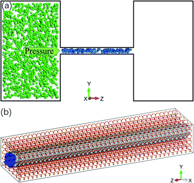 |
| | Fig. 1 Molecular dynamics simulation system. (a) Schematic of the system: a quartz nanochannel with two reservoirs at the ends (blue and green spheres are methane and CO2 molecules). (b) Atomic structure of quartz nanochannel. | |
The DREIDING force field40 is employed to describe the quartz channel, methane, and methane–channel interactions. The general potential for these interactions is given by
| |
 | (1) |
where
K0 is a force constant,
R0 and
θ0 are the equilibrium bond distance and angle,
B0 is the barrier height,
d0 is the phase factor,
n0 is the periodicity,
ε is the binding energy and
σ is the collision diameter,
rij is the separation between molecules/atoms
i and
j,
θ is the bond angle,
ϕ is the bond torsion angle, and
q is the charge. The values of relevant parameters for various interactions are listed in
Table 1, where the bond stretch, bond angle bend, torsional, and Lennard-Jones parameters are adopted from the original DREIDING potential.
40 However, the charges for the electrostatic potential are estimated using the Gasterier method,
41 which have been confirmed by previous work.
31,42
Table 1 Potential parameters for the force field
| Bond stretch parameters |
| Bond type |
K0 (kcal mol−1 Å−2) |
R0 (Å) |
| C–H |
700 |
1.09 |
| Si–O |
700 |
1.587 |
| C–O |
1400 |
1.152 |
| Bond angle bend parameters |
| Bond type |
K0 (kcal mol−1 Å−2) |
θ0 |
| H–C–H |
100 |
109.471° |
| Si–O–Si |
100 |
104.51° |
| O–Si–O |
100 |
109.471° |
| O–C–O |
100 |
180 |
| Torsional parameters |
| Torsion type |
B0 (kcal mol−1) |
d0 |
n0 |
| O–Si–O–Si |
2 |
−1 |
3 |
| Lennard-Jones parameters |
| Interaction type |
σ (Å) |
ε (kcal mol−1) |
| H–H |
3.195 |
0.015 |
| C–C |
3.898 |
0.095 |
| H–C |
3.547 |
0.038 |
| H–O |
3.3 |
0.038 |
| H–Si |
3.733 |
0.069 |
| C–O |
3.651 |
0.095 |
| C–Si |
4.084 |
0.172 |
| O–O |
3.405 |
0.096 |
| O–Si |
3.838 |
0.173 |
| Electrostatic parameters |
| Element type |
Charge (e) |
| C in methane |
−0.4 |
| C in carbon dioxide |
0.572 |
| H |
0.1 |
| O in carbon dioxide |
−0.286 |
| O in quartz |
−0.445 |
| Si |
0.89 |
The cut-off distance for the potential is set at 10.5 Å and the time step is 1 fs. Initially, the reservoirs and the nanochannel are not connected (they are separated by a wall) and the system is relaxed for 200 ps in the (N, V, T) ensemble. After the relaxation, the walls between the reservoirs and the nanochannel are removed so that CO2 molecules can infiltrate into the channel. At the same time, the system is performed in the (N, V, E) ensemble to calculate the release percentage of methane molecules.
3. Results and discussion
By varying the pressure of CO2 and the channel diameter, the number of methane molecules expelled from the channel is obtained and the release percentage of methane is computed as| |
 | (2) |
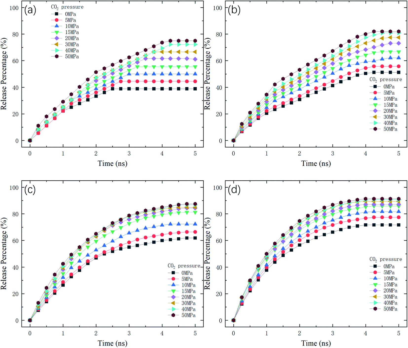
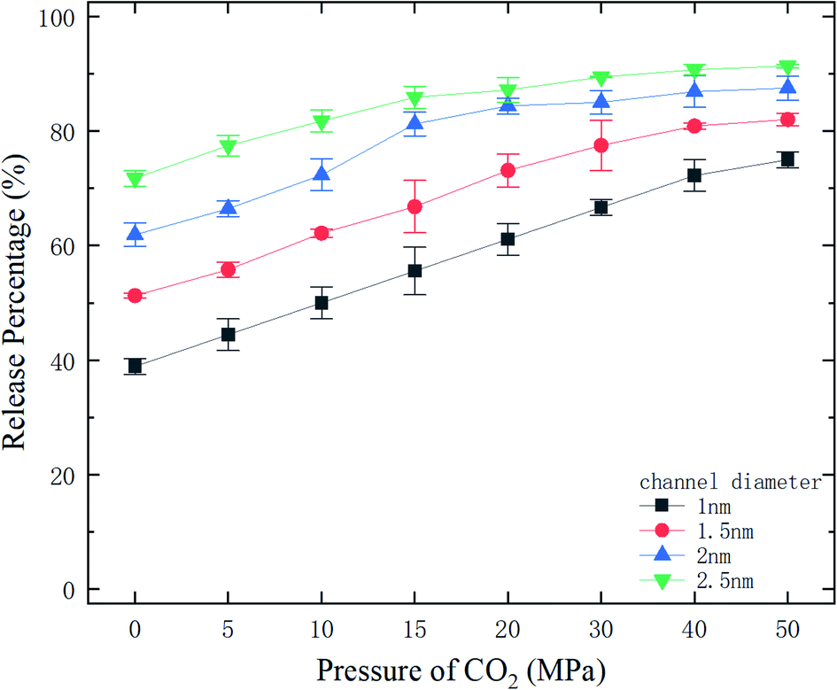
where N is the number of methane molecules released from the channel, i.e., the number of methane molecules in the reservoirs, and N0 is the total number of methane molecules in the system. Fig. 2 shows the release percentage as a function of time for different channel diameters under various CO2 pressures. It is seen that Pr approaches constant values in 5 ns regardless of the channel size and CO2 pressure. The final release percentage is depicted in Fig. 3. It is found that Pr increases as the pressure of CO2 is raised. At zero CO2 pressure, i.e., initially no CO2 in the left reservoir, Pr is about 40% for 1 nm-diameter channel, while it is about 70% for 2.5 nm diameter channel. This is because the reservoirs initially are vacuum and the high methane pressure inside the channel drives some methane molecules into the reservoirs. For 1 and 1.5 nm-diameter channels, Pr increases and eventually reaches about 80% and 85%, respectively, as the pressure of CO2 increases, which indicates that the method of displacement using CO2 works well. In 2 nm and 2.5 nm diameter channels, as the storage capacity of the channels for methane is weak, even if there is no CO2 injection, Pr is over 60%. With CO2 injection, Pr reaches about 90% and 95%, which demonstrates that the method of displacement is still useful for relatively large diameters.
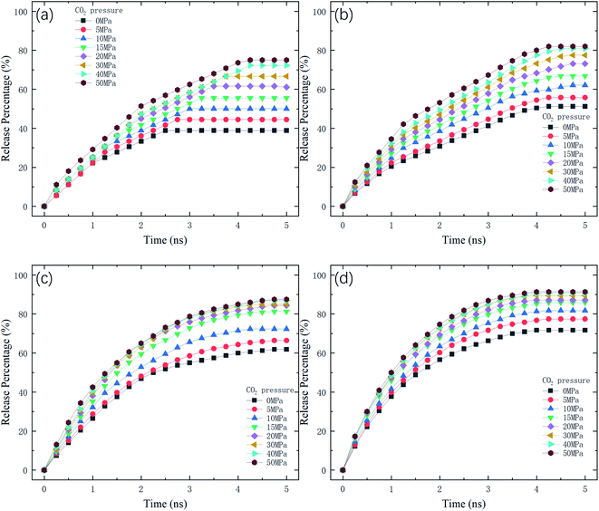 |
| | Fig. 2 Release percentage of methane as a function of time at different CO2 pressures in channels with various diameters D. (a) D = 1 nm. (b) D = 1.5 nm. (c) D = 2 nm. (d) D = 2.5 nm. | |
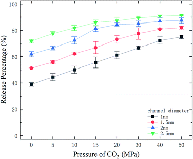 |
| | Fig. 3 The final release percentages of methane as a function of CO2 pressure. | |
Whether a methane molecule can be released from the channel or not mainly depends on the kinetic energy E of the methane molecule and the energy barrier ΔG in the channel.43–45 E is mainly determined by the temperature T and ΔG is governed by the methane–quartz molecular interaction and the pore structure. ΔG is the potential difference between the maximum and minimum potential points in the channel. If the kinetic energy of a methane molecule is sufficiently high, it can overcome the energy barrier and can be released from the channel. The probability for the methane molecules to escape from the attraction of the channel is proportional to exp(−ΔG/E), as will be discussed later.
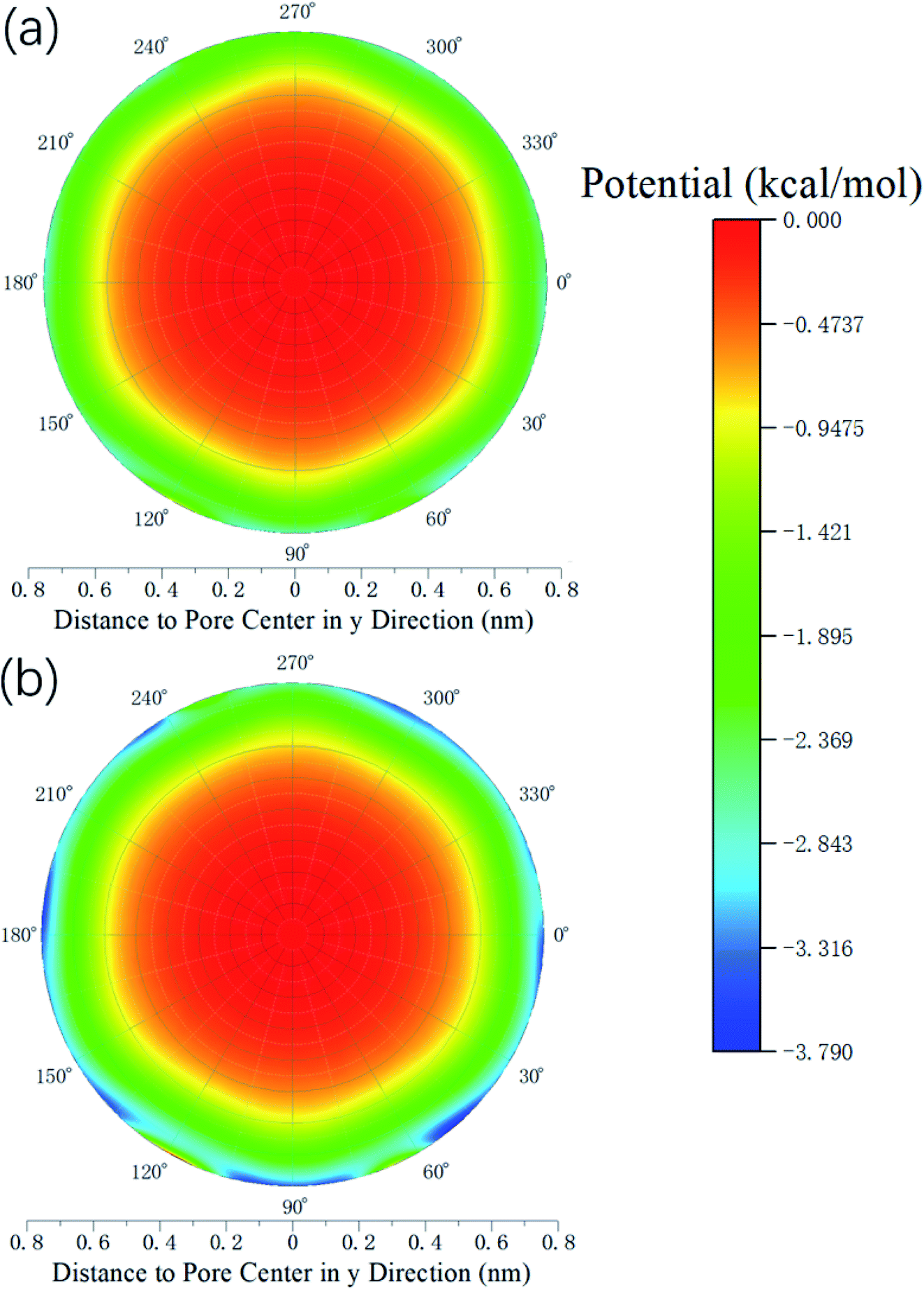
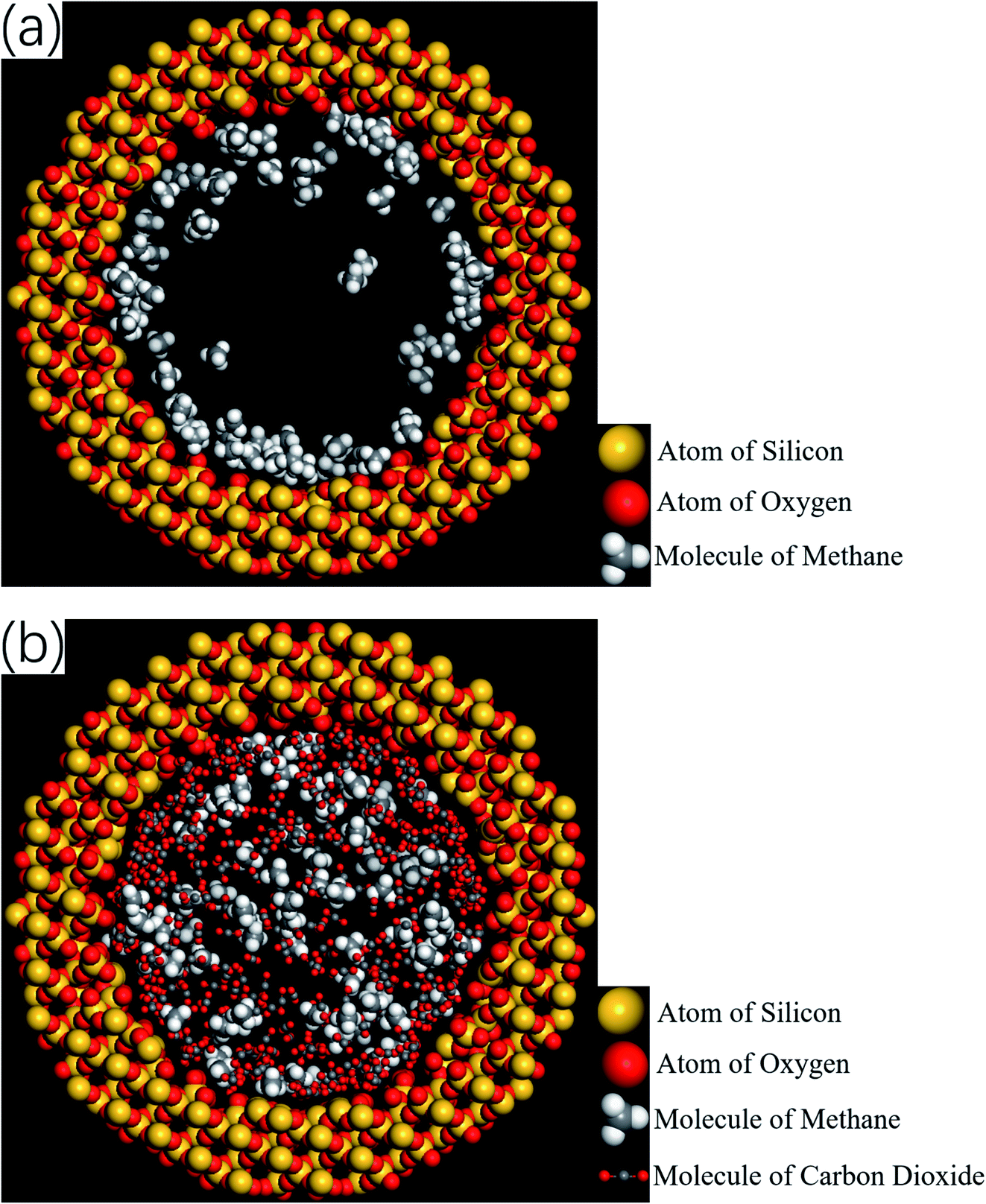
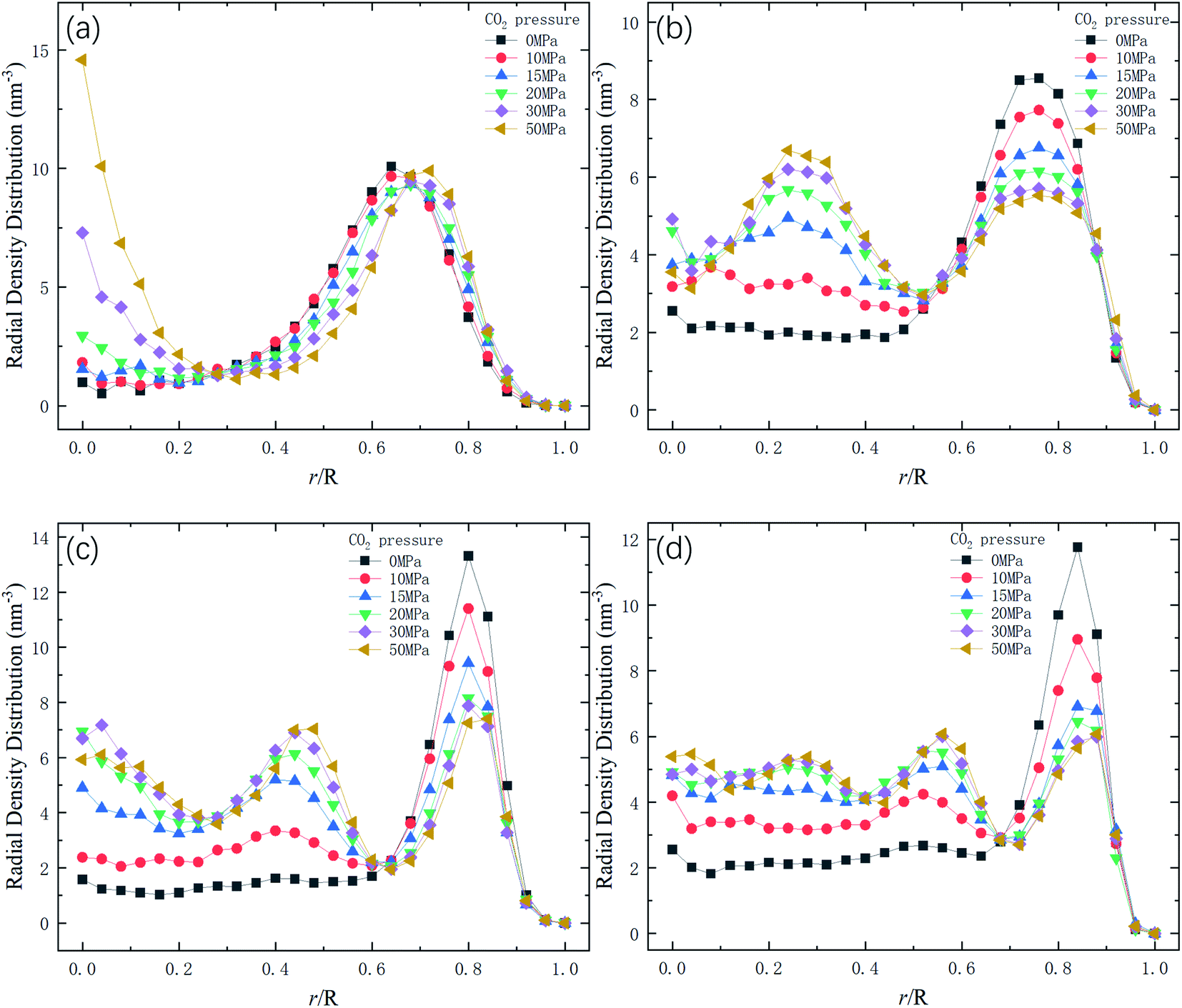
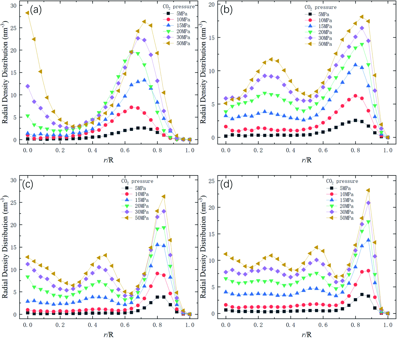
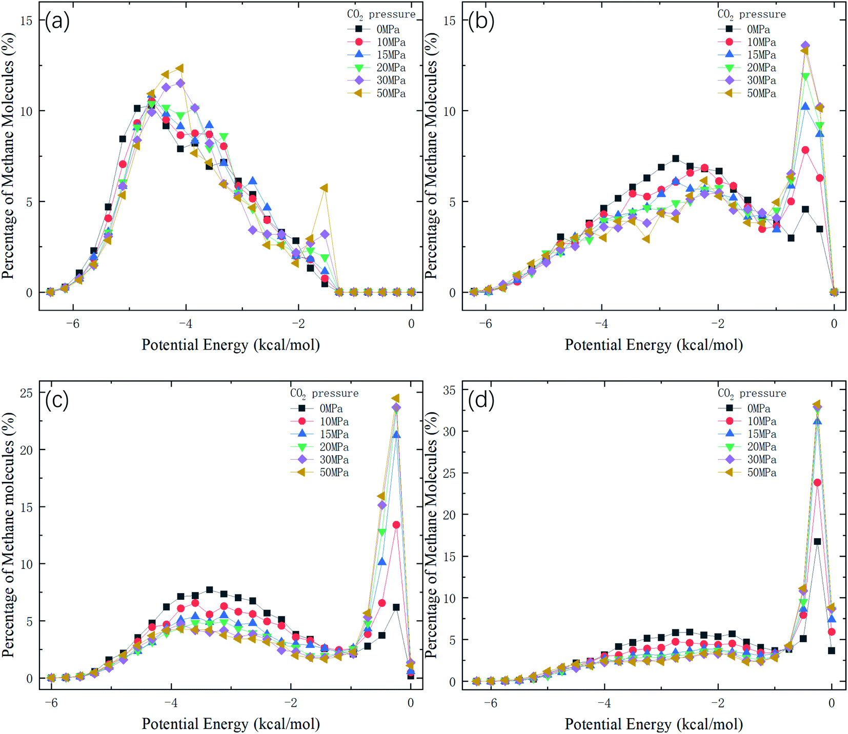
Therefore, the release percentage of methane can be enhanced by either increasing the kinetic energy E of methane molecules or reducing the energy barrier ΔG of the channel. In previous work,46,47 we explored the method of increasing the kinetic energy E by heating or applying an external force on the channel to release methane from nanopores. Herein, by injecting CO2, we expect to decrease the energy barrier ΔG in the channel through the displacement of methane molecules to increase the release percentage of methane. Fig. 4a and b show the potential distribution of methane and carbon dioxide, respectively, inside the 2 nm-diameter channel in a plane perpendicular to the channel axis. In Fig. 4a, it is seen that the potential energy of methane next to the wall is low and that at the center area is high. The low potential close to the wall is caused by strong methane–wall interactions, which lead to the adsorption of methane molecules on the channel surface, as demonstrated in Fig. 5a. As CO2 molecules are injected into the channel, CO2 molecules replace methane molecules on the adsorption sites of the channel wall because the CO2–wall intermolecular interaction is stronger than that between methane and the wall, as indicated by the potential distribution in Fig. 4 (the potential energy of methane next to the wall is about 3 kcal mol−1 while that of carbon dioxide is about 3.8 kcal mol−1). Consequently, some methane molecules are replaced by carbon dioxide molecules and freed from adsorption, as shown in Fig. 5b, which makes them easier to be released from the channel because the energy barrier to be overcome becomes smaller, as will be shown later. The replacement of methane molecules by CO2 molecules can be manifested by the density distribution of methane in the channel as the pressure of CO2 is varied, as depicted in Fig. 6. It is seen that the density of methane next to the wall decreases while the density around the center area increases as the CO2 pressure is increased due to the adsorption of CO2 on the channel surface and the replacement of methane by CO2. Fig. 7 shows the density distribution of CO2 in the channel. It is clear that many CO2 molecules are adsorbed by the channel surface and the adsorption is enhanced by the pressure. Fig. 7 confirms that CO2 molecules can replace methane molecules efficiently. Fig. 8 shows the fraction of methane molecules as a function of potential energy in nanochannels. It is seen that the number of methane molecules with low potential energy decreases as the pressure of CO2 is increased, which reduces the energy barrier for methane molecules, as will be shown later, and consequently increase the release percentage of methane.
 |
| | Fig. 4 Potential distribution inside the 2 nm-diameter channel in a plane perpendicular to the channel axis. (a) Methane (b) CO2. | |
 |
| | Fig. 5 Snapshots of simulations showing the spatial distributions of methane and CO2 molecules. (a) Before the injection of CO2 (the majority of methane molecules are adsorbed by the channel wall). (b) After the injection of CO2 (some adsorbed methane molecules are replaced by CO2 molecules and driven into the inner area of the channel). | |
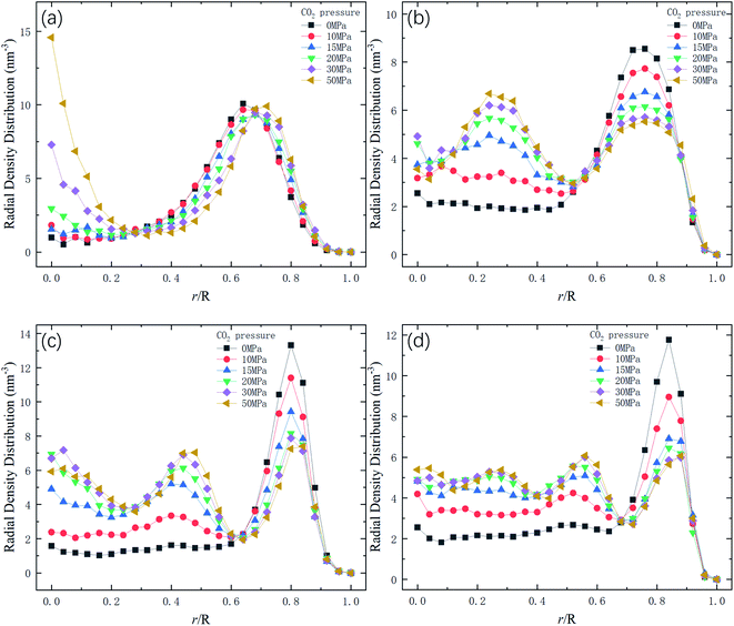 |
| | Fig. 6 Radial density distribution of methane in channels of different diameters D. R is the radius of the channel. (a) D = 1 nm. (b) D = 1.5 nm. (c) D = 2 nm. (d) D = 2.5 nm. | |
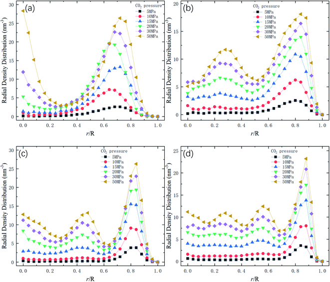 |
| | Fig. 7 Radial density distribution of carbon dioxide in channels of different diameters D. R is the radius of nanochannels. (a) D = 1 nm. (b) D = 1.5 nm. (c) D = 2 nm. (d) D = 2.5 nm. | |
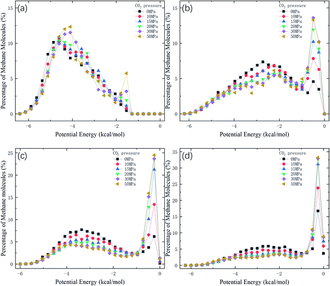 |
| | Fig. 8 Distribution of potential energy of methane in channels of different diameters D. (a) D = 1 nm. (b) D = 1.5 nm. (c) D = 2 nm. (d) D = 2.5 nm. | |
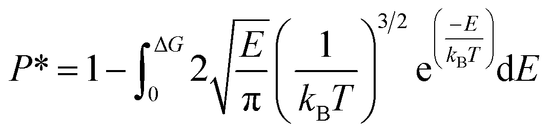
As mentioned previously, the release percentage of methane molecules can be theoretically predicted using E and ΔG. Similar to the velocity, the kinetic energy of methane molecules follows the Maxwell–Boltzmann distribution,
| |
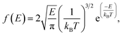 | (3) |
where
kB is the Boltzmann constant. If the potential energy barrier in the quartz nanochannels is denoted as Δ
G, the release percentage can be theoretically predicted as
| |
 | (4) |
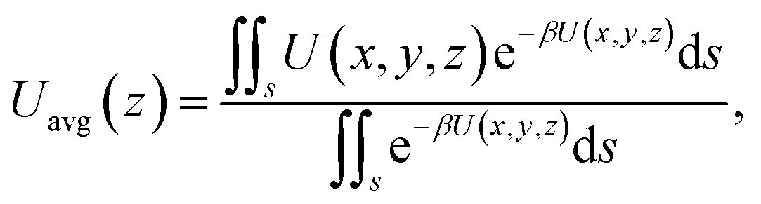
The results of eqn (4) is proportional to exp(−ΔG/kBT), i.e., P* ∝ exp(−ΔG/kBT). As ΔG is governed by the potential distribution inside the channels, and the potential U depends on the nature of atoms and position of molecules in the channels, the average potential Uavg(z) along the axis of the channels is employed to obtain ΔG. Uavg(z) is calculated through
| |
 | (5) |
where
s is the area of adsorption site of methane molecules (for the cases without CO
2 injection and at low CO
2 pressures,
s is the an interior surface next to the channel; at high CO
2 injection pressures,
s is the whole inner space of the channel,
i.e.,
r/
R = 0–0.65, where
R is the radius of channel) and
β = 1/
kBT. Δ
G is calculated as the potential difference between the point where
Uavg(
z) is the highest and the point where
Uavg(
z) is the minimum.
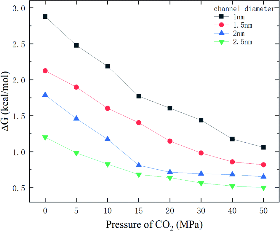
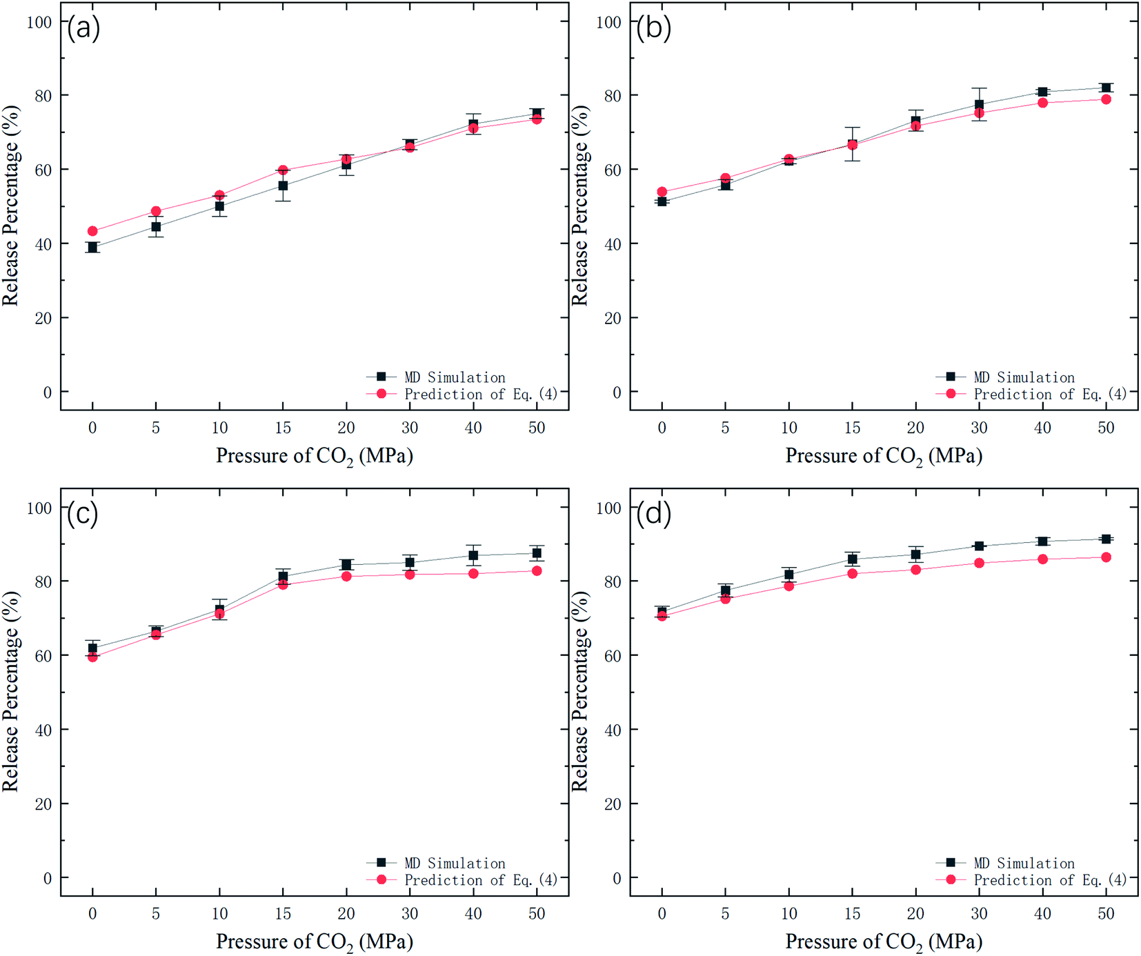
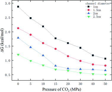
Fig. 9 shows the potential energy barrier ΔG for methane as a function of CO2 pressure in different nanochannels. It is seen that ΔG in small-diameter channels is higher than that in large-diameter channels. This is why the release percentage in small channels is relatively low, as shown in Fig. 3. Furthermore, ΔG decreases with increasing CO2 pressure due to the displacement of methane by CO2. On the basis of the ΔG values in Fig. 9, the release percentages predicted by eqn (4) are shown in Fig. 10. It is seen that the theoretical predictions are in good agreement with the MD results. The discrepancy is caused by the estimation of ΔG, which is obtained using the average potential in the channels.
 |
| | Fig. 9 Energy barrier ΔG as a function of CO2 pressure. | |
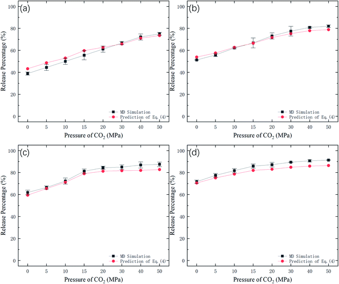 |
| | Fig. 10 Methane release percentage from MD simulations and theoretical predictions of eqn (4). | |
With the ΔG data in Fig. 9, the variation of the release percentage in Fig. 3 can be explained. For a small-diameter nanochannel, when CO2 is injected into the channel, CO2 molecules occupy most of the space next to the channel wall and drive the methane molecules to the center area, which greatly reduces ΔG and increases the release percentage of methane (Fig. 3). In large nanochannels, ΔG is relatively small and is not sensitive to the CO2 pressure (Fig. 8). This is why the release percentage of methane is high, even at low CO2 pressures.
4. Conclusions
The displacement of methane molecules by carbon dioxide in nanochannels of different pore sizes has been studied through MD simulations. As the intermolecular interaction between carbon dioxide and the quartz nanochannel is stronger than the methane–channel interaction, some methane molecules are replaced by carbon dioxide molecules and expelled to the center area of the channel, where reduces the energy barrier for the transport of methane and consequently enhances the release percentage of methane. Theoretical predictions for the methane release percentage using the kinetic energy of methane and the energy barrier in the channel are also calculated, which are in good agreement with MD simulations.
Conflicts of interest
There are no conflicts of interest to declare.
Acknowledgements
This work was supported by the Research Grants Council of the Hong Kong Special Administrative Region (No. 16209119) and the Basic Science Center Program for Ordered Energy Conversion of the National Natural Science Foundation of China (No. 51888103).
References
- Q. Wang and R. Li, Renewable Sustainable Energy Rev., 2017, 74, 715–720 CrossRef.
- Y. Yang, L. Wang, Y. Fang and C. Mou, Renewable Sustainable Energy Rev., 2017, 76, 1465–1478 CrossRef CAS.
- M. Guo, X. Lu, C. P. Nielsen, M. B. McElroy, W. Shi, Y. Chen and Y. Xu, Renewable Sustainable Energy Rev., 2016, 66, 742–750 CrossRef.
- V. Arora and Y. Cai, Appl. Energy, 2014, 120, 95–103 CrossRef.
- E. Krogulec and K. Sawicka, Episodes, 2015, 38, 9–20 CrossRef PubMed.
- A. Krupnick and H. Gordon, Agricultural and Resource Economics Review, 2015, 44, 106–119 CrossRef.
- A. Vengosh, R. B. Jackson, N. Warner, T. H. Darrah and A. Kondash, Environ. Sci. Technol., 2014, 48, 8334–8348 CrossRef CAS PubMed.
- J. D. Hughes, Nature, 2013, 494, 307–308 CrossRef CAS PubMed.
- T. A. Ho, L. J. Criscenti and Y. Wang, Sci. Rep., 2016, 6, 28053 CrossRef CAS PubMed.
- W. Dang, J.-C. Zhang, X. Tang, X.-L. Wei, Z.-M. Li, C.-H. Wang, Q. Chen and C. Liu, Geosci. Front., 2018, 9, 559–575 CrossRef CAS.
- D. Dasani, Y. Wang, T. T. Tsotsis and K. Jessen, Ind. Eng. Chem. Res., 2017, 56, 9953–9963 CrossRef CAS.
- T. F. T. Rexer, M. J. Benham, A. C. Aplin and K. M. Thomas, Energy Fuels, 2013, 27, 3099–3109 CrossRef CAS.
- G. P. Lithoxoos, A. Labropoulos, L. D. Peristeras, N. Kanellopoulos, J. Samios and I. G. Economou, J. Supercrit. Fluids, 2010, 55, 510–523 CrossRef CAS.
- X. Zhu and Y.-P. Zhao, J. Phys. Chem. C, 2014, 118, 17737–17744 CrossRef CAS.
- H. Wu, J. Chen and H. Liu, J. Phys. Chem. C, 2015, 119, 13652–13657 CrossRef CAS.
- K. Bartus and A. Brodka, Mol. Phys., 2011, 109, 1691–1699 CrossRef CAS.
- S. J. Mahdizadeh and S. F. Tayyari, Theor. Chem. Acc., 2011, 128, 231–240 Search PubMed.
- L. Liu, C. Hu, D. Nicholson and S. K. Bhatia, Langmuir, 2017, 33, 6280–6291 CrossRef CAS PubMed.
- L. Huang, L. Zhang, Q. Shao, L. Lu, X. Lu, S. Jiang and W. Shen, J. Phys. Chem. C, 2007, 111, 11812–11920 CrossRef PubMed.
- L. Lu, S. Wang, E. A. Muller, W. Cao, Y. Zhu, X. Lu and G. Jackson, Fluid Phase Equilib., 2014, 362, 227–234 CrossRef CAS.
- L. Liu, D. Nicholson and S. K. Bhatia, Chem. Eng. Sci., 2015, 121, 268–278 CrossRef CAS.
- W. Cao, L. Lu, M. Zhou, G. M. Tow, L. Huang, T. Yang and X. Lu, Mol. Simul., 2017, 43, 502–509 CrossRef.
- L. Hong, D. Gao, J. Wang and D. Zheng, AIP Adv., 2020, 10, 015338 CrossRef CAS.
- H. Yu, J. Yuan, W. Guo, J. Cheng and Q. Hu, Int. J. Coal Geol., 2008, 73, 156–166 CrossRef CAS.
- S. Bhowmik and P. Dutta, Energy Fuels, 2011, 25, 2730–2740 CrossRef CAS.
- P. Huo, D. Zhang, Z. Yang, W. Li, J. Zhang and S. Jia, Int. J. Greenhouse Gas Control, 2017, 66, 48–59 CrossRef CAS.
- J. Shi, L. Gong, S. Sun, Z. Huang, B. Ding and J. Yao, RSC Adv., 2019, 9, 25326–25335 RSC.
- H. Zhang and D. Cao, Chem. Eng. Sci., 2016, 156, 121–127 CrossRef CAS.
- H. Sun, H. Zhao, N. Qi and Y. Li, J. Phys. Chem. C, 2017, 121, 10233–10241 CrossRef CAS.
- T. A. Ho, Y. Wang, Y. Xiong and L. J. Criscenti, Fuel, 2018, 220, 1–7 CrossRef CAS.
- Q. Yuan, X. Zhu, K. Lin and Y.-P. Zhao, Phys. Chem. Chem. Phys., 2015, 17, 31887–31893 RSC.
- Y. Yang, A. K. N. Nair and S. Sun, J. Phys. Chem. C, 2020, 124, 16478–16487 CrossRef CAS.
- P. Li, Z. Jiang, M. Zheng, H. Bi and L. Chen, J. Nat. Gas Sci. Eng., 2016, 34, 1034–1043 CrossRef CAS.
- K. Ji, S. Guo and B. Hou, J. Pet. Sci. Eng., 2017, 150, 250–256 CrossRef CAS.
- C. Zou, Q. Zhao, D. Dong, Z. Yang, Z. Qiu, F. Liang, N. Wang, Y. Huang, A. Duan, Q. Zhang and Z. Hu, J. Nat. Gas Geosci., 2017, 2, 273–288 CrossRef.
- H. Berendsen, J. P. M. Postma, W. van Gunsteren, A. D. DiNola and J. R. Haak, J. Chem. Phys., 1984, 81, 3684–3690 CrossRef CAS.
- M. Parrinello and A. Rahman, J. Appl. Phys., 1981, 52, 7182–7190 CrossRef CAS.
- U. Setzmann and W. Wagner, J. Phys. Chem. Ref. Data, 1991, 20, 1061–1155 CrossRef CAS.
- R. Span and W. Wagner, J. Phys. Chem. Ref. Data, 1996, 25, 1509–1596 CrossRef CAS.
- S. L. Mayo, B. D. Olafson and W. A. Goddard, J. Phys. Chem., 1990, 94, 8897–8909 CrossRef CAS.
- J. Gasteiger and M. Marsili, Tetrahedron, 1980, 36, 3219–3228 CrossRef CAS.
- J. Xiong, K. Liu, L. Liang and Q. Zeng, RSC Adv., 2016, 16, 110808–110819 RSC.
- R. L. June, A. T. Bell and D. N. Theodorou, J. Phys. Chem., 1990, 94, 8232–8240 CrossRef CAS.
- Q. Yang and C. Zhong, J. Phys. Chem. B, 2006, 110, 17776–17783 CrossRef CAS PubMed.
- T. F. Rexer, E. J. Mathia, A. C. Aplin and K. M. Thomas, Energy Fuels, 2014, 28, 2886–2901 CrossRef CAS.
- X. Cheng, Z. Li and Y.-L. He, RSC Adv., 2020, 10, 37507–37514 RSC.
- X. Cheng, Z. Li and Y.-L. He, RSC Adv., 2019, 9, 9546–9554 RSC.
|
| This journal is © The Royal Society of Chemistry 2021 |
Click here to see how this site uses Cookies. View our privacy policy here. 
 Open Access Article
 This Open Access Article is licensed under a Creative Commons Attribution-Non Commercial 3.0 Unported Licence
 a,
Zhigang Li
a,
Zhigang Li