 Open Access Article
Fabrication of one dimensional hierarchical WO3/BiOI heterojunctions with enhanced visible light activity for degradation of pollutants
Xiaoxiao Luab,
Qiang Li *ab,
Lijie Wangab,
Wen Jiangab,
Rui Luoab,
Min Zhangab,
Chaopeng Cuiab,
Zhenfei Tian*ab and
Guangping Zhuab
aCollege of Physics and Electronic Information, Huaibei Normal University, Huaibei, 235000, P. R. China. E-mail: qiangli@chnu.edu.cn; tianzhenfei@126.com
bAnhui Province Key Laboratory of Pollutant Sensitive Materials and Environmental Remediation, Huaibei Normal University, Huaibei, 235000, P. R. China
First published on 5th May 2021
Abstract
One-dimensional (1D) hierarchical WO3/BiOI p–n (WB) heterojunctions with different mass percentages of WO3 were fabricated through a precipitation process. Various analytical techniques were employed to characterize the resulting WB composites, and their photocatalytic properties were measured by the degradation of rhodamine B (RhB) and methylene blue (MB) under irradiation of visible light. The WB heterojunctions showed largely enhanced photocatalytic performance as compared to the pure photocatalysts. Notably, the degradation rate constant of RhB by WB-10 was 3.3 and 33.6 times higher than those of pure BiOI and WO3, respectively. The enhanced activity could be attributed to the hierarchical p–n heterostructures, which can supply more reaction sites and effectively promote the separation of photogenerated charge carriers, as confirmed by PL and photocurrent. Trapping experiments implied that holes (h+) and superoxide anion radicals (˙O2−) were the dominant active species for organic pollutants decomposition on the WB composites. This work may benefit the construction of hierarchical heterostructures with high photocatalytic efficiency.
1. Introduction
With industrialization and sharp increase of the population, water pollution is becoming more and more serious, which needs to be solved urgently. So far, a variety of strategies have been explored to eliminate the kinds of pollutants found in aquatic environments, such as microwave-induced catalytic degradation,1 electrochemical filtration2 electrosorption,3 etc. Among them, semiconductor photocatalysis has been deemed as an efficient and clean technology to purify wastewater because of its advantages in economic conservation, easy operation and being environmentally friendly.4,5 Many semiconductors were explored as photocatalysts, such as BiVO4,6 TiO2,7 Bi2MoO6,8 Ag3PO4 (ref. 9) and Bi2WO6.10 However, the low photocatalytic efficiency greatly restricted the practical application of a single semiconductor since it was incapable of simultaneously possessing lower band gaps and efficient charge separation. Fortunately, heterojunction design based on multi-component semiconductors makes it possible for humans to fabricate more effective photocatalysts for environmental remediation.Recently, one-dimensional (1D) hierarchical heterostructures made up of two-dimensional (2D) nanosheets and 1D nanowires or nanorods generally have excellent photocatalytic performance and attracted a lot of attention due to their larger surface area and improved separation efficiency.11–13 As a member of bismuth oxyhalides (BiOX, X = Cl, Br, I), BiOI is easily to form unique layered structure and possesses narrow band gap (Eg = 1.7–1.9 eV) with excellent visible light absorption capacity.14–16 It has been acknowledged as a promising p-type semiconductor in photocatalytic17 and photoelectrochemical fields.18–20 However, the fast recombination rate of e−/h+ pairs in BiOI greatly limited its activity.21 Many strategies like surface engineering22 and heterojunction design23,24 have been made to enhance the activity of BiOI. Among these, constructing heterojunctions by coupling BiOI with another semiconductors has been suggested as an effective way to facilitate the separation and transfer of e−/h+ pairs.16,25 For example, Wei et al. prepared hierarchical Bi2O3/BiOI heterojunction, and its photocatalytic activity for Cr(VI) reduction was significantly enhanced than Bi2O3 and BiOI.26 Wang et al. also reported that hierarchical TiO2/BiOI p–n heterojunctions displayed enhanced photocatalytic activity towards the removal of methyl orange.27 Nonetheless, it is still necessary to construct high-efficient BiOI based composites photocatalysts.
Tungsten trioxide (WO3), as one outstanding class of n-type semiconductor, has been widely utilized in the field of photocatalysis because of its non-toxicity, low cost, good photostability as well as strong oxidization ability.28,29 In spite of this, the photocatalytic efficiency of WO3 still need to be improved because of some inherent drawbacks, such as low separation efficiency of charge carriers and relative large bandgap (∼2.7 eV). To improve the photocatalytic efficiency of WO3, lots of WO3-based heterojunctions have been constructed, for instance, WO3/AgI,30 WO3/Bi12O17Cl2 (ref. 31) and WO3/CuBi2O4,32 and the photocatalytic efficiency of these heterojunctions was significantly improved. In addition, hierarchical WO3/BiOBr heterojunctions fabricated by growing BiOBr nanosheets on WO3 nanotube bundles could remove 94.7% ciprofloxacin hydrochloride under visible light irradiation within 120 min.33
Herein, a series of 1D hierarchical WB heterostructures with different mass percentage of WO3 were successfully synthesized by coupling BiOI nanoflakes on the surface of WO3 nanorods. The obtained hierarchical WB as well as WO3 and BiOI were carefully characterized and their mineralization ability was tested by decomposition of RhB or MB under visible light irradiation. Compared with pure WO3 and BiOI, the hierarchical WB heterostructures showed enhanced photocatalytic property towards the decomposition of dyes, which could be put down to a p–n heterostructure formed between WO3 and BiOI that effectively promoted the separation and transfer of electrons and holes.
2. Experimental section
2.1 Synthesis of samples
All chemicals were analytical grade reagents, and used as received without further purification. WO3 nanorods were fabricated by hydrothermal method according to a previous report.34 To be specific, 0.99 g sodium tungstate dehydrate and 1.19 g sodium hydrogen sulfate monohydrate were dissolved in 40 mL deionized water (DW). Subsequently, the above solution was moved to a Teflon-lined stainless-steel autoclave. The hydrothermal reaction was operated at 180 °C for 24 hours. Finally, the precipitate was collected and rinsed with DW and ethanol several times, and then dried at 80 °C for one night.The 1D hierarchical WB heterojunctions were synthesized through a precipitation method.35 Firstly, a certain number of WO3 was distributed in 30 mL DW by ultrasonic treatment, then a solution made up of 30 mL ethylene glycol and 2 mmol bismuth nitrate pentahydrate was added into the WO3 suspension. The above mixture solution was stirred for 0.5 hours. Subsequently, an aqueous solution of KI (10 mL of DW, 0.332 g KI) was dropwise added into the above mixture solution. After stirring for 5 hours, the precipitate was collected by centrifugation and washed with DW and ethanol for 5 times. The sediment was dried overnight at 70 °C. The WB heterojunctions with different weight percent of WO3 (5%, 10% and 20%) were named as WB-5, WB-10 and WB-20, respectively. For comparison, bare BiOI was also synthesized via the same method without WO3.
2.2 Materials characterization
The X-ray diffraction (XRD) patterns of catalysts were acquired on the X-ray diffractometer with Cu Kα radiation. The morphology and structure were characterized by a field emission scanning electron microscope (FESEM, SU8220, Hitachi, Japan) equipped with an energy dispersive X-ray (EDX) spectroscope. Transmission electron microscopy (TEM) and high-resolution TEM (HRTEM) were performed on a FEI Tecnai TF20. The UV-vis diffuse reflectance spectra (DRS) of all samples were obtained on a UV-vis spectrophotometer (PerkinElmer Lambda 950). Elemental composition and surface chemical state of photocatalyst were determined with X-ray photoelectron spectroscopy (XPS, ESCALAB 250Xi). The Brunauer–Emmett–Teller (BET) surface area of the catalyst was measured by N2 adsorption on SASP 2460 (Micromeritics, USA). The photoluminescence (PL) spectrum of the samples was obtained on the steady-state transient fluorescence spectrometer (FLS 920).2.3 Photocatalytic experiment
The photocatalytic performance of all as-synthesized photocatalysts was measured by decomposition of RhB or MB irradiated by visible light. The light source was supplied by a 500 W xenon lamp equipped with a 400 nm filter. Briefly, 30 mg catalyst was dispersed in 100 mL RhB (15 mg L−1) or MB (10 mg L−1) aqueous solutions. Then, the above solution was violently stirred for one hour in dark to get adsorption–desorption equilibrium before visible light irradiation. During the photocatalytic reaction, 4 mL solution was taken out in a certain interval of time and the catalyst was removed by centrifugation. The concentration of RhB (or MB) was measured by UV-vis spectrophotometer according to characteristic peak at 554 nm (or 664 nm).2.4 Photoelectrochemical test
Transient photocurrent response of photocatalysts was tested on a CHI 760E electrochemical workstation with a standard three-electrode system. A Pt wire and Ag/AgCl electrode was employed as the counter electrode and reference electrode, respectively. The electrolyte solution was Na2SO4 (0.2 M) aqueous solution. Working electrodes were prepared as follows: 30 mg catalyst was dispersed in a mixture of 100 μL ethanol and 20 μL Nafion for grinding. Then, the slurry was dip-coated onto a 1.5 × 1.5 cm2 FTO glass electrode.3. Results and discussion
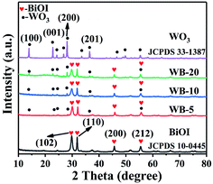
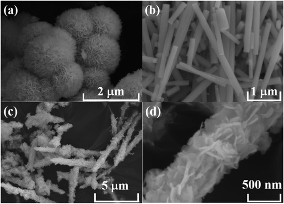
The crystal structures of WO3, BiOI, WB-5, WB-10 and WB-20 were characterized by XRD, and the results were exhibited in Fig. 1. For pure WO3, the distinct diffraction peaks at 13.9°, 22.7°, 28.2° and 36.6° can be indexed to the (100), (001), (200) and (201) crystal planes of hexagonal WO3 (JCPDS no. 33-1387).36 As for BiOI, the characteristic diffraction peaks located at 29.6°, 31.7°, 45.4° and 55.2°, were belonged to (102), (110), (200) and (212) crystal planes of tetragonal BiOI (JCPDS no. 10-0445).35 As for the WB composites, with increase of WO3 content, the diffraction peak intensity of WO3 became stronger while that of BiOI gradually weakens, suggesting the coexistence of both WO3 and BiOI phases in the WB composites.FESEM was used to study the microstructure of WO3, BiOI and WB composites. As displayed in Fig. 2(a), BiOI shows floral structure with approximately 2 μm in size, which consists of abundant 2D interlaced nanoflakes. Fig. 2(b) displays that WO3 has a rod-like structure, the length and diameter of the nanorods are about 2–4 μm and 200–400 nm, respectively. The SEM images of WB-10 were shown in Fig. 2(c and d). As we can see, a large amount of BiOI nanoflakes were grown on the surface of the WO3 nanorods, which formed 1D hierarchical structures. This hierarchical structures photocatalysts would increase the specific surface area and supply more reactive sites.
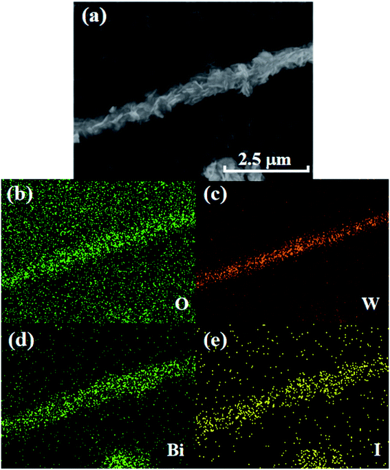
EDX elemental mapping was employed to further study elemental composition and distribution of WB-10 composite, as shown in Fig. 3(b–e). The elemental mapping spectra indicated that the Bi, I, W and O elements coexisted in the WB-10 sample. Furthermore, the EDX mapping analysis of WB-10 also revealed the BiOI nanoflakes evenly distributed on the surface of WO3 nanorods. Therefore, the results of SEM and EDX analyses suggest that the WO3 nanorods were anchored by BiOI nanoflakes.
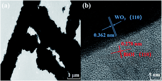
The morphological information of the WB heterojunction was also revealed by TEM and HRTEM. As displayed in Fig. 4(a), the 1D WO3 nanorods were covered by numerous BiOI nanosheets, which was in accordance with the results of SEM. Meanwhile, HRTEM image (Fig. 4(b)) showed two types of lattice fringes, the lattice fringe spacings were 0.362 and 0.278 nm, which were attributed to (110) plane of hexagonal WO3 and (110) plane of tetragonal BiOI, respectively.
XPS was employed to detect the surface elemental composition and chemical state of the as-synthesized WB-10. As shown in Fig. 5(a), W, Bi, I and O were observed in survey spectrum, indicating the successful assembling of BiOI and WO3. Two distinct peaks appeared at 158.7 and 164.0 eV were corresponding to atomic orbitals of Bi 4f7/2 and Bi 4f5/2,26,37,38 respectively (Fig. 5(b)). Fig. 5(c) exhibits two peaks centered at 618.4 and 630.0 eV, which related to I 3d5/2 and I 3d3/2,39 respectively. In addition, two peaks (Fig. 5(d)) situated at the binding energy of 35.4 and 37.6 eV were attributed to W 4f7/2 and W 4f5/2, respectively.33 The O 1s spectrum (Fig. 5(e)) can be fitted with three peaks, two peaks at the binding energy of 529.8 and 530.3 eV were assigned to lattice oxygen of Bi–O or W–O bonds, respectively, while the peak located at 531.7 eV was indexed to hydroxyl groups.33
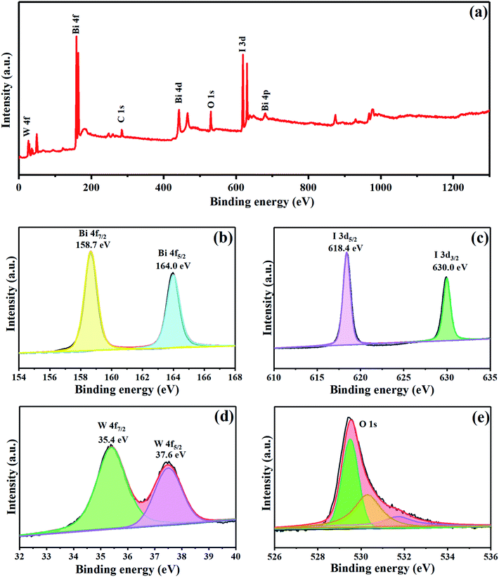 | ||
| Fig. 5 XPS spectra of WB-10 composite (a) survey spectra of the sample, high resolution XPS spectra of (b) Bi 4f, (c) I 3d, (d) W 4f and (e) O 1s. | ||
The light absorption spectra of all samples were shown in Fig. 6(a), both WO3 and BiOI can respond to the visible light, and the absorption edge of bare WO3 and BiOI was ca. 430 and 650 nm, respectively. For the WB composite, the absorption edge was between that of WO3 and BiOI. The band gaps of BiOI and WO3 can be calculated by Kubelka–Munk formula: αhν = A(hν − Eg)n/2, where α, h, ν, Eg and A were the absorption coefficient, Planck constant, light frequency, band gap energy and constant, respectively.40 Additionally, n depended on the optical transition mode of semiconductor: n = 1 for direct transition and n = 4 for indirect transition. WO3 and BiOI were both indirect band gap semiconductors.41,42 Therefore, the band gaps of WO3 and BiOI (Fig. 6(b)) were 2.67 and 1.79 eV, respectively, which was similar to the previous reports.33,35
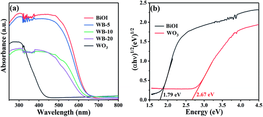 | ||
| Fig. 6 (a) UV-vis absorption spectra of all as-prepared photocatalysts and (b) plots of (αhν)1/2 versus energy for the band gap energy of BiOI and WO3. | ||
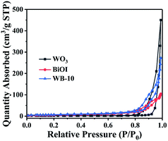
To investigate specific surface area of WO3, BiOI and WB-10, the N2 adsorption–desorption analysis was performed. As displayed in Fig. 7, the BET surface areas of pure WO3, pure BiOI and WB-10 composite were 6.1, 21.1 and 25.4 m2 g−1, respectively. Among them, WB-10 composite has the highest specific surface area. The larger surface areas can supply more reaction sites, and higher photocatalytic performance can be expected.
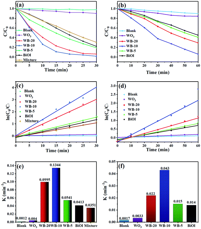
The mineralization ability of samples was measured by degrading RhB under visible light illumination. As illustrated in Fig. 8(a), a blank experiment without photocatalysts evidenced the high stability of RhB under visible-light irradiation. Bare BiOI and WO3 showed low photocatalytic activity, on which about 77.9% and 10.0% of RhB dyes were removed under 30 min irradiation. With respect to the WB composites, when the two semiconductors coupled together, they displayed much higher mineralization ability than BiOI and WO3. Particularly, WB-10 exhibited the best photocatalytic property, and it can degrade 98.2% of RhB within 30 min. The excellent photocatalytic performance can be put down to higher separation efficiency of photoexcited e−/h+ pairs and larger specific surface area compared to the bare BiOI and WO3. To further study the significant influence of heterojunction on the photocatalytic performance of WB catalysts, WB-10 was compared to physical mixture (WO3 + BiOI, 1![[thin space (1/6-em)]](https://www.rsc.org/images/entities/char_2009.gif) :
:![[thin space (1/6-em)]](https://www.rsc.org/images/entities/char_2009.gif) 9) for the removal of RhB under visible light irradiation. The RhB degradation efficiency over the mixture was only 69.5%, which was much lower than that of WB-10 composite. This suggests that heterogeneous junctions were formed between WO3 and BiOI, which effectively promotes the separation and transfer of the photogenerated e−/h+ pairs.
9) for the removal of RhB under visible light irradiation. The RhB degradation efficiency over the mixture was only 69.5%, which was much lower than that of WB-10 composite. This suggests that heterogeneous junctions were formed between WO3 and BiOI, which effectively promotes the separation and transfer of the photogenerated e−/h+ pairs.
MB dye was further used to evaluate the photocatalytic activity of WB heterojunction. Fig. 8(b) presents that all the WB heterojunction photocatalysts showed higher photocatalytic activity than single-component sample. The degradation percentages of MB were about 15.7%, 54.8%, 59.2%, 94.0% and 70.8% for WO3, BiOI, WB-5, WB-10 and WB-20, respectively. Obviously, WB-10 still exhibited the highest degradation capacity towards MB degradation. The content of WO3 in WB composites was vital to their mineralization ability. The photocatalytic activity of WB first increased then decreased with increasing content of WO3. This could be due to the reason that excess WO3 might decrease quantities of heterojunctions and active sites, resulting in inferior photocatalytic performance.
The degradation kinetics of the RhB or MB with the as-prepared samples were obtained by the pseudo-first-order kinetic model:43 ln(C0/C) = Kappt, where C and C0 are the concentration of dyes at illumination time t (min) and initial time t0 (min), respectively, Kapp refers to reaction rate constant. As displayed in Fig. 8(c and d), the removal of RhB or MB with different photocatalysts was accorded with the first-order reaction dynamics, and the reaction rate constant (K) were given in Fig. 8(e and f). The K values for RhB degradation over WO3, BiOI, WB-5, WB-10, WB-20 and mixture were 0.004, 0.0413, 0.0541, 0.1344, 0.0995 and 0.0351 min−1, respectively (Fig. 8(e)). The K value of the WB-10 was the highest, which was about 33.6, 3.3 and 3.8-folds higher than pure WO3, BiOI and the mixture. Consistent with the removal of RhB, the K value of MB degradation by WB-10 was also highest, which was 3.1 and 13 times higher than those of BiOI and WO3. These results demonstrated that WB-10 exhibited excellent photocatalytic performance towards removal of pollutants.
For the purpose of studying the effect of inorganic ions on the degradation efficiency of RhB, some inorganic ions (Cl−, NO3−, CO32− and SO42−) were added to the RhB solution. Fig. 9(a) presents that the addition of Cl− and NO3− had slight influence to the RhB degradation with WB-10. Oppositely, the photocatalytic efficiency was declined markedly in the presence of CO32− and SO42−. Fig. 9(b) shows degradation kinetic curves and rate constant of RhB degradation by WB-10. The K values for WB-10 in the presence of Cl−, NO3−, CO32− and SO42− were calculated to be 0.123, 0.116, 0.0004 and 0.021 min−1, respectively (Fig. 9(b)). Compared to the K value (0.1344 min−1) without ion addition, the degradation rate of RhB was largely decreased in the presence of CO32− and SO42−, which was similar to the previous literature.44
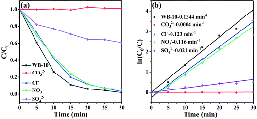 | ||
| Fig. 9 (a) The effect of different anions on RhB degradation over WB-10 catalyst under visible light irradiation, (b) the corresponding reaction kinetic curves. | ||
To study the separation, migration and recombination rate of photogenerated carriers in catalysts, photoluminescence spectroscopy (PL) and transient photocurrent response were obtained. As shown in Fig. 10(a), the PL intensity of WB-10 composite was much lower than that of pristine BiOI and WO3, indicating WB-10 has the lowest charge carrier recombination rate. Moreover, the photocurrent test was also executed to assess the charge separation of BiOI, WO3 and WB-10. As displayed in Fig. 10(b), all the three samples exhibited stable photocurrent response. WB-10 showed much higher current than that of pure WO3 and BiOI, which further provided evidence that electron–hole recombination rate in the WB-10 heterjunction was the lowest. According to the results of photocurrent and PL, separation and transfer efficiency of photoexcited e−/h+ pairs can be improved by coupling BiOI with WO3, hence enhance photocatalytic performance was obtained.
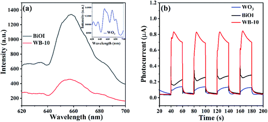 | ||
| Fig. 10 (a) Photoluminescence spectra and (b) transient photocurrent responses of pure BiOI, pure CoTiO3 and WB-10 composite. | ||
To assess the reusability and stability of the WB heterojunction, recycling degradation experiment was carried out, where the catalyst with the optimal photocatalytic performance was employed to remove RhB under visible light irradiation. As presented in Fig. 11(a), after four consecutive cycles, the degradation percentage of RhB with WB-10 composite dropped to 79.7%, which could be due to the inevitable loss of sample during the cycling experiment. Additionally, the XRD patterns of the WB-10 composite before and after consecutive cycles were shown in Fig. 11(b), there were negligible changes of the phase structure, which indicated the moderate stability of WB-10 photocatalyst during the decomposition of RhB.
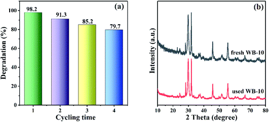 | ||
| Fig. 11 Stability tests of WB photocatalyst. (a) Recycle experiments of photodegradation of RhB over WB-10 composite, (b) XRD patterns of WB-10 composite before and after 4 runs. | ||
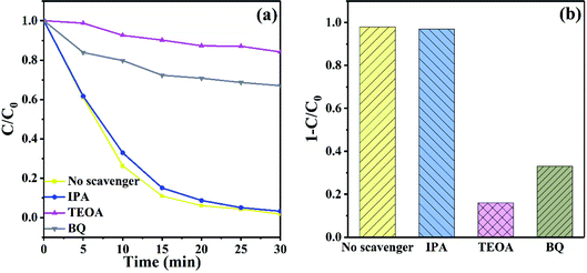
To explore the role of active species in degradation of RhB with WB-10, isopropanol (IPA), triethanolamine (TEOA) and p-benzoquinone (BQ) were introduced to quench hydroxyl radical (˙OH), hole (h+) and superoxide radical (˙O2−), respectively. As displayed in Fig. 12(a), when IPA was introduced, the decomposition of RhB was hardly affected, suggesting ˙OH was not the main active species in photodegradation process. Nevertheless, the removal of RhB was significantly inhibited after addition of TEOA and BQ, suggesting that h+ and ˙O2− were the main reactive species in photodegradation process. Fig. 12(b) exhibits the histogram of the degradation of RhB by WB-10 composite in the presence of various sacrificial agents. When TEOA and BQ were added, the degradation efficiency of RhB declined to 15% and 35%, respectively, which were much lower than the situation without any scavenger. These results suggested that h+ played the most crucial role in photodegradation of RhB, followed by superoxide radicals, and hydroxyl radicals showed negligible effect.
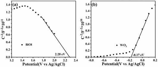
The Mott–Schottky (MS) tests were performed to determine the flat band potential (Ef) and the conductive type of BiOI and WO3. As shown in Fig. 13(a), the positive slope of the WO3 manifested that it was an n-type semiconductor with electron conduction, while the BiOI exhibited a p-type nature due to the negative slope for the MS plot (Fig. 13(b)). Additionally, the Ef values of BiOI and WO3 were 2.28 and −0.17 eV vs. Ag/AgCl, respectively. Based on the formula: ENHE = EAg/AgCl + E0Ag/AgCl, where E0Ag/AgCl = 0.20 V, the Ef of BiOI and WO3 were 2.48 and 0.03 eV vs. NHE, respectively. Here, the Ef of p-type semiconductor was 0.1 eV higher than valence band (VB), and the Ef of n-type semiconductor was 0.1 eV lower than conduction band (CB).45 Therefore, the VB of BiOI and the CB of WO3 were 2.58 and −0.07 eV, respectively. Consequently, the CB of BiOI and VB of WO3 were calculated to be 0.76 and 2.6 eV, respectively.
Based on the above analyses, a possible mechanism of pollutants degradation over WB p–n junctions was proposed in Fig. 14. Before contact, the Ef of BiOI located close to its VB while that of WO3 was near to its CB. After BiOI nanosheets were combined with WO3 nanorods, because of the higher Ef of n-type semiconductor, the electrons transferred from WO3 to BiOI, while holes migrated from BiOI to WO3 until their Ef reached equilibrium. As a result, the holes gathered in WO3 region while electrons accumulated in BiOI region, hence a built-in electric field was formed, which can accelerate the transfer of charge carriers.46,47 When the WB composites were illuminated with visible light, the electrons in both WO3 and BiOI were excited from their VB to the CB, leaving holes on their VB. Then, the electrons on the CB of BiOI rapidly transferred to the CB of WO3 and the holes on the VB of WO3 rapidly transferred to the VB of BiOI under the drive of the inner electric field. Consequently, the separation and transfer of photogenerated carriers were significantly improved, which was beneficial to the improvement of photocatalytic performance. The electrons were then captured by O2 to generate ˙O2−, which could effectively oxidize organic pollutants. In addition, the holes on the VB of BiOI could directly degrade the organic pollutants.
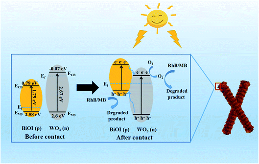 | ||
| Fig. 14 Schematic diagrams of formation of p–n junction and proposed charge separation process in the WO3/BiOI composites under visible light irradiation. | ||
4. Conclusions
In summary, the 1D hierarchical WB p–n heterojunctions with various mass percent of WO3 were successfully synthetized via precipitating BiOI nanoflakes on the surface of the WO3 nanorods. The hierarchical WB heterojunctions exhibited much superior photocatalytic performance than bare BiOI and WO3 toward the removal of RhB or MB induced by visible light. Especially, WB-10 heterojunction exhibited the highest photodegradation efficiency. The extraordinary degradation of RhB or MB proved the universality for enhanced visible-light photocatalytic performance of the WB-10. Notably, degradation rate of RhB over WB-10 was 3.3 and 33.6-folds higher than that of pure BiOI and WO3, respectively. The largely improved photocatalytic property can be put down to the formation of hierarchical p–n junctions, which increased specific surface area as well as enhanced the separation of photoinduced charge. However, the photoefficiency of RhB on WB-10 was decreased remarkably in the presence of CO32− and SO42−.Conflicts of interest
There are no conflicts to declare.Acknowledgements
We gratefully acknowledge the financial support of National College Students Innovation and Entrepreneurship Training Program of China (202010373017), the Natural Science Foundation of Anhui Province (1908085QF293 and 1908085QA36) and Foundation of Educational Commission of Anhui Province (KJ2018A0394, KJ2018A0393, KJ2016SD53 and KJ2019B14).References
- S. Liu, L. Mei, X. Liang, L. Liao, G. Lv, S. Ma, S. Lu, A. Abdelkader and K. Xi, ACS Appl. Mater. Interfaces, 2018, 10, 29467–29475 CrossRef CAS PubMed.
- Y. Liu, H. Liu, Z. Zhou, T. Wang, C. Ong and C. Vecitis, Environ. Sci. Technol., 2015, 49, 7974–7980 CrossRef CAS PubMed.
- C. Song, B. Guo, X. Sun, S. Wang and Y. Li, Chem. Eng. J., 2019, 358, 1139–1146 CrossRef CAS.
- X. Hu, G. Wang, J. Wang, Z. Hu and Y. Su, Appl. Surf. Sci., 2020, 511, 145499 CrossRef CAS.
- L. Zhi, S. Zhang, Y. Xu, J. Tu, M. Li, D. Hu and J. Liu, J. Colloid Interface Sci., 2020, 579, 754–765 CrossRef CAS PubMed.
- W. Zhao, J. Li, B. Dai, Z. Cheng, J. Xu, K. Ma, L. Zhang, N. Sheng, G. Mao, H. Wu, K. Wei and D. Leung, Chem. Eng. J., 2019, 369, 716–725 CrossRef CAS.
- Y. Wang, C. Zhu, G. Zuo, Y. Guo, W. Xiao, Y. Dai, J. Kong, X. Xu, Y. Zhou, A. Xie, C. Sun and Q. Xian, Appl. Catal., B, 2020, 278, 119298 CrossRef CAS.
- M. Li, D. Li, Z. Zhou, P. Wang, X. Mi, Y. Xia, H. Wang, S. Zhan, Y. Li and L. Li, Chem. Eng. J., 2020, 382, 122762 CrossRef CAS.
- B. Borjigin, L. Ding, H. Li and X. Wang, Chem. Eng. J., 2020, 402, 126070 CrossRef CAS.
- J. Wang, J. Wang, N. Li, X. Du, J. Ma, C. He and Z. Li, ACS Appl. Mater. Interfaces, 2020, 12, 31477–31485 CrossRef CAS PubMed.
- J. Tian, P. Hao, N. Wei, H. Cui and H. Liu, ACS Catal., 2015, 5, 4530–4536 CrossRef CAS.
- H. Hou and X. Zhang, Chem. Eng. J., 2020, 395, 125030 CrossRef CAS.
- G. Zhang, D. Chen, N. Li, Q. Xu, H. Li, J. He and J. Lu, Appl. Catal., B, 2019, 250, 313–324 CrossRef CAS.
- N. Wang, L. Shi, L. Yao, C. Lu, Y. Shi and J. Sun, RSC Adv., 2018, 8, 537–546 RSC.
- L. Cai, J. Yao, J. Li, Y. Zhang and Y. Wei, J. Alloys Compd., 2019, 783, 300–309 CrossRef CAS.
- P. Mafa, B. Mamba and A. Kuvarega, Sep. Purif. Technol., 2020, 253, 117349 CrossRef CAS.
- K. Wangkawong, S. Phanichphant, D. Tantraviwat and B. Inceesungvorn, J. Taiwan Inst. Chem. Eng., 2020, 108, 55–63 CrossRef CAS.
- H. Chen, Y. Peng, T. Chen, K. Chen, K. Chang, Z. Dang, G. Lu and H. He, Sci. Total Environ., 2018, 633, 1198–1205 CrossRef CAS PubMed.
- Q. Han, R. Wang, B. Xing, T. Zhang, M. Khan, D. Wu and Q. Wei, Biosens. Bioelectron., 2018, 99, 493–499 CrossRef CAS PubMed.
- Y. Zhang, Q. Wang, D. Liu, Q. Wang, T. Li and Z. Wang, Appl. Surf. Sci., 2020, 521, 146434 CrossRef CAS.
- X. Wen, C. Niu, L. Zhang and G. Zeng, ACS Sustainable Chem. Eng., 2017, 5, 5134–5147 CrossRef CAS.
- X. Wang, Y. Zhang, C. Zhou, D. Huo, R. Zhang and L. Wang, Appl. Catal., B, 2020, 268, 118390 CrossRef CAS.
- J. Li, X. Yu, Y. Zhu, X. Fu and Y. Zhang, J. Alloys Compd., 2021, 850, 156778 CrossRef CAS.
- H. Qin, K. Wang, L. Jiang, J. Li, X. Wu and G. Zhang, J. Alloys Compd., 2020, 821, 153417 CrossRef CAS.
- L. Huang, L. Yang, Y. Li, C. Wang, Y. Xu, L. Huang and Y. Song, Appl. Surf. Sci., 2020, 527, 146748 CrossRef CAS.
- Z. Wei, N. Zheng, X. Dong, X. Zhang, H. Ma, X. Zhang and M. Xue, Chemosphere, 2020, 257, 127210 CrossRef CAS PubMed.
- K. Wang, C. Shao, X. Li, F. Miao, N. Lu and Y. Liu, Materials, 2016, 9, 90 CrossRef PubMed.
- S. Zhang, S. Chen, D. Liu, J. Zhang and T. Peng, Appl. Surf. Sci., 2020, 529, 147013 CrossRef CAS.
- J. Luo, X. Zhou, L. Ma and X. Xu, J. Mol. Catal. A: Chem., 2015, 410, 168–176 CrossRef CAS.
- T. Wang, W. Quan, D. Jiang, L. Chen, D. Li, S. Meng and M. Chen, Chem. Eng. J., 2016, 300, 280–290 CrossRef CAS.
- J. Zheng, F. Chang, M. Jiao, Q. Xu, B. Deng and X. Hu, J. Colloid Interface Sci., 2018, 510, 20–31 CrossRef CAS PubMed.
- L. Wang, T. Huang, G. Yang, C. Lu, F. Dong, Y. Li and W. Guan, J. Hazard. Mater., 2020, 381, 120956 CrossRef CAS PubMed.
- Y. Ling and Y. Dai, Appl. Surf. Sci., 2020, 509, 145201 CrossRef CAS.
- J. Li, X. Liu, Q. Han, X. Yao and X. Wang, J. Mater. Chem. A, 2013, 1, 1246–1253 RSC.
- H. Huang, Y. He, X. Du, P. Chu and Y. Zhang, ACS Sustainable Chem. Eng., 2015, 3, 3262–3273 CrossRef CAS.
- S. Zeb, G. Sun, Y. Nie, Y. Cui and X. Jiang, Sens. Actuators, B, 2020, 321, 128439 CrossRef CAS.
- G. Lee, Y. Chien, S. Anandan, C. Lv, J. Dong and J. Wu, Int. J. Hydrogen Energy, 2021, 46, 5949–5962 CrossRef CAS.
- F. Zhang, H. Peng, S. Jiang, C. Wang, X. Xu and L. Wang, Environ. Sci. Pollut. Res. Int., 2019, 26, 8226–8236 CrossRef CAS PubMed.
- C. Zhang, W. Fei, H. Wang, N. Li, D. Chen, Q. Xu, H. Li, J. He and J. Lu, J. Hazard. Mater., 2020, 399, 123109 CrossRef CAS PubMed.
- J. Medina, N. Portillo-Vélez, M. Bizarro, A. Hernández-Gordillo and S. Rodil, Dyes Pigm., 2018, 153, 106–116 CrossRef CAS.
- M. Kang, J. Liang, F. Wang, X. Chen, Y. Lu and J. Zhang, Mater. Res. Bull., 2020, 121, 110614 CrossRef CAS.
- M. Qiao, H. Liu, J. Lv, G. Xu, X. Zhang, X. Shu and Y. Wu, Nano, 2019, 14, 1950112 CrossRef CAS.
- L. Ma, G. Wang, C. Jiang, H. Bao and Q. Xu, Appl. Surf. Sci., 2018, 430, 263–272 CrossRef CAS.
- B. Zhang, D. Zhang, Z. Xi, P. Wang, X. Pu, X. Shao and S. Yao, Sep. Purif. Technol., 2017, 178, 130–137 CrossRef CAS.
- J. Xu, B. Feng, Y. Wang, Y. Qi, J. Niu and M. Chen, Front. Chem., 2018, 6, 393 CrossRef CAS PubMed.
- Y. Cheng, H. Li, B. Liu, L. Jiang, M. Liu, H. Huang, J. Yang, J. He and J. Jiang, Small, 2020, 16, 2005217 CrossRef CAS.
- Y. Cheng, K. Shan, Y. Xu, J. Yang, J. He and J. Jiang, Nanoscale, 2020, 12, 21798–21811 RSC.
| This journal is © The Royal Society of Chemistry 2021 |

