DOI:
10.1039/D1RA01485D
(Paper)
RSC Adv., 2021,
11, 19316-19322
A novel MnO–CrN nanocomposite based non-enzymatic hydrogen peroxide sensor†
Received
24th February 2021
, Accepted 3rd May 2021
First published on 27th May 2021
Abstract
A MnO–CrN composite was obtained via the ammonolysis of the low-cost nitride precursors Cr(NO3)3·9H2O and Mn(NO3)2·4H2O at 800 °C for 8 h using a sol–gel method. The specific surface area of the synthesized powder was measured via BET analysis and it was found to be 262 m2 g−1. Regarding its application, the electrochemical sensing performance toward hydrogen peroxide (H2O2) was studied via applying cyclic voltammetry (CV) and amperometry (i–t) analysis. The linear response range was 0.33–15![[thin space (1/6-em)]](https://www.rsc.org/images/entities/char_2009.gif) 000 μM with a correlation coefficient (R2) value of 0.995. Excellent performance toward H2O2 was observed with a limit of detection of 0.059 μM, a limit of quantification of 0.199 μM, and sensitivity of 2156.25 μA mM−1 cm−2. A short response time of within 2 s was achieved. Hence, we develop and offer an efficient approach for synthesizing a new cost-efficient material for H2O2 sensing.
000 μM with a correlation coefficient (R2) value of 0.995. Excellent performance toward H2O2 was observed with a limit of detection of 0.059 μM, a limit of quantification of 0.199 μM, and sensitivity of 2156.25 μA mM−1 cm−2. A short response time of within 2 s was achieved. Hence, we develop and offer an efficient approach for synthesizing a new cost-efficient material for H2O2 sensing.
Introduction
Hydrogen peroxide (H2O2) plays two important roles in living bodies. On one hand, it is involved in essential processes, like cell signaling and fighting microbial trespassers. On the other hand, it is associated with malfunction, ageing, and even cell death.1,2 In the reactive oxygen species family, H2O2 is an important member, and it is considered the most long-lived of the more reactive oxygen species (living longer than hydroxyl radicals and superoxide anions, for instance). It accumulates inside and outside of cells, where it is involved in both vital (signaling) and deadly (toxic) reactions depending on its concentration3–5. As a reactive oxygen species, H2O2 is involved in a variety of redox reactions within the living body.6,7 From kinetics studies, the most common range for H2O2 in healthy human plasma is 1–5 μM.8 Maintaining reactive oxygen species levels at or below this certain threshold concentration is essential for cellular endurance.2 The quantification of reactive oxygen species concentrations remains challenging and it is frequently not accomplished in biomedical studies due to a lack of suitable methods. To quantify these levels, electrochemical-based enzymatic/non-enzymatic sensors have been developed.9,10
Electrochemical biosensors based on the enzymatic catalysis of a reaction produce or consume electrons (redox enzymes). They work via direct electron transfer from proteins or the redox states of connected species that are changed in response to intermediate redox counterparts in protein prosthetic groups or appropriate co-substrates at active sites11. Enzymatic sensors have quick response times but they are very costly and only have low detection limits close to neutral pH, where they also have limited stabilities12. Biosensors also cannot be used for tracing extracellularly released H2O2 in cells because of the inadequate electron transfer activity, and the reactivity of immobilized enzymes is poor due to the lack of direction of immobilized enzymes on the electrode surface. Low reproducibility and insufficient stability have restricted the broad use of enzymatic sensors. Hence, non-enzymatic electrochemical H2O2 sensors are desirable.
Other than applications in living organisms, non-enzymatic sensors are also essential in the clinical,13 medical,14 food,15 packaging, and waste treatment fields. Therefore, developing a selective, rapid, and accurate H2O2 sensor with a wide detection range is of great interest to the environmental monitoring, pharmaceutical, and food industries. Measuring H2O2 with extremely high sensitivity usually requires horseradish peroxidase (HRP), mediators, or precious metal nanoparticles, resulting in the problems of low long-term operational stability and rising cost. Therefore, new materials are required for non-enzymatic sensors.
Recently, manganese-oxide compounds have received special attention on account of their prominent advantages, as they are low-cost, earth-abundant, and environmentally friendly, and they show considerable ORR activity. Generally, MnO2 is a semiconductor material,16 so we combined it with CrN as a conduction support material and synthesized a new material at the nano-level via a new facile synthesis method. It was established that the catalytic activity of the MnO–CrN composite surface is stimulated in the presence of hetero atoms (N, O, or others).17 Moreover, structural substitution is a well-known reactive approach for enhancing conductivity and increasing the functionality of materials, mostly with mixed valence species (e.g., MnOx, CrOx, etc.). Redox reactions between Cr3+ and Mn oxidants were designed to control structural substitution via the use of a narrow onset potential range. We prepared hierarchical nitrogen-implanted MnO–CrN composite nanoparticles. The advantage of electrochemical sensors based on nanoparticles is that they can decrease the over-potentials of many analytes compared with unmodified electrodes.18–20 The novelty of this work is that we demonstrated, for the first time, MnO–CrN2 nanoparticles obtained via a very simple sol–gel synthesis method that can act as an excellent electrocatalyst. They show high electrocatalytic activity toward the reduction of H2O2 and achieve the highly sensitive detection of H2O2 with a small detection time and quick reproducibility for subsequent measurements. Table 1 summarizes research relating to non-enzymatic sensors for H2O2.
Table 1 A comparison of non-enzymatic electrochemical sensors for H2O2
| Electrode |
Linear range (mM) |
LOD (μM) |
Sensitivity (μA mM−1 cm−2) |
Ref. |
| MnO2 |
0.00008–12.78 |
0.02 |
Not given |
21 |
| GO/MnO2 |
0.0049–4.5 |
0.48 |
191 |
22 |
| MnO2/Nafion |
0.001–0.015 |
2.0 |
400 |
23 |
| Ag–MnO2 MWCNTs |
0.005–10.4 |
1.7 |
82.5 |
24 |
| MnO2/carbon fiber |
0.012–0.26 |
5.4 |
10.6 |
25 |
| MnO2 nanosheets/chitosan |
0.005–3.5 |
1.5 |
130.56 |
26 |
| MnO2 NPs-CNFs |
0.01–15 |
1.1 |
71 |
27 |
| MnO2–GO |
0.005–0.6 |
0.8 |
38.2 |
28 |
| Chromium(III) hexacyanoferrate(II) |
0.01–1.3 |
0.03 |
0.1152 |
29 |
| Chromium(III) dicarboxylate MOF |
25–500 |
3.52 |
11.9 |
30 |
| MnO–CrN composite |
0.0003–15 |
0.059 |
2156.25 |
This work |
Experimental
Chemicals and reagents
All chemicals were purchased and utilized without any additional refinement.
Synthesis of the MnO–CrN nanocomposite
In a typical synthesis method, Cr(NO3)3·9H2O and Mn(NO3)2·4H2O were dissolved at a 1:1 molar ratio in 30 ml of ethylene glycol under continuous stirring; the temperature was raised to 70 °C and maintained at this level for 1 h. After 1 h, we slowly added 2 M citric acid to the mixed metal solution under continuous stirring. The solution was maintained for a further 1 h and the temperature was raised to 180 °C. At this temperature, a sol–gel was obtained. To get the xerogel, it was put in an oven at 450 °C for 4 h. The material was ground using a pestle and mortar. Finally, the MnO–CrN composite was obtained via the ammonolysis of the xerogel at 800 °C for 8 h under NH3(g) flow.
Characterization techniques
The MnO–CrN composite synthesized after ammonolysis at 800 °C for 8 h under NH3(g) flow was characterized using different techniques. The crystalline phase was studied using a MiniFlex 600 X-ray automated diffractometer using a monochromatic Cu-Kα source with λ = 0.1542 nm, V = 40 kV, and I = 15 mA. Phase identification information was collected over a 2θ angular range of 10–90° at a scanning rate of 1° min−1 to improve the accuracy. The morphology and microstructure were analyzed via scanning electron microscopy (SEM; JSM-7800F, Japan), operating at 15 kV, and transmission electron microscopy (TEM; FEI Tecnai F20) measurements. The pore-volume and surface-area measurements for the nitride material were performed applying Brunauer–Emmett–Teller (BET) theory and using an Accelerated Surface Area and Porosimetry system (ASAP 2420).
Fabrication of the MnO–CrN modified electrode
Prior to the modification of the electrode, a mirror-smooth bare polished glassy carbon electrode (GCE) was obtained via using three different grades of alumina slurry: first 0.5 μm, then 0.1 μm, and finally 0.03 μm. The polished GCE was then washed using deionized water, ethanol, and deionized water again for 5 min consecutively. The GCE was dried using a nitrogen stream. The as-prepared MnO–CrN sample (5 mg) was uniformly dispersed in isopropanol:water (4:1) to make a homogenous ink. The MnO–CrN ink (3 μl) was dropped onto the surface of the GCE and was allowed to dehydrate at less than 60 °C in a drying oven for 10 min to obtain the MnO–CrN-modified electrode (MnO–CrN/GCE).
Results and discussion
XRD analysis
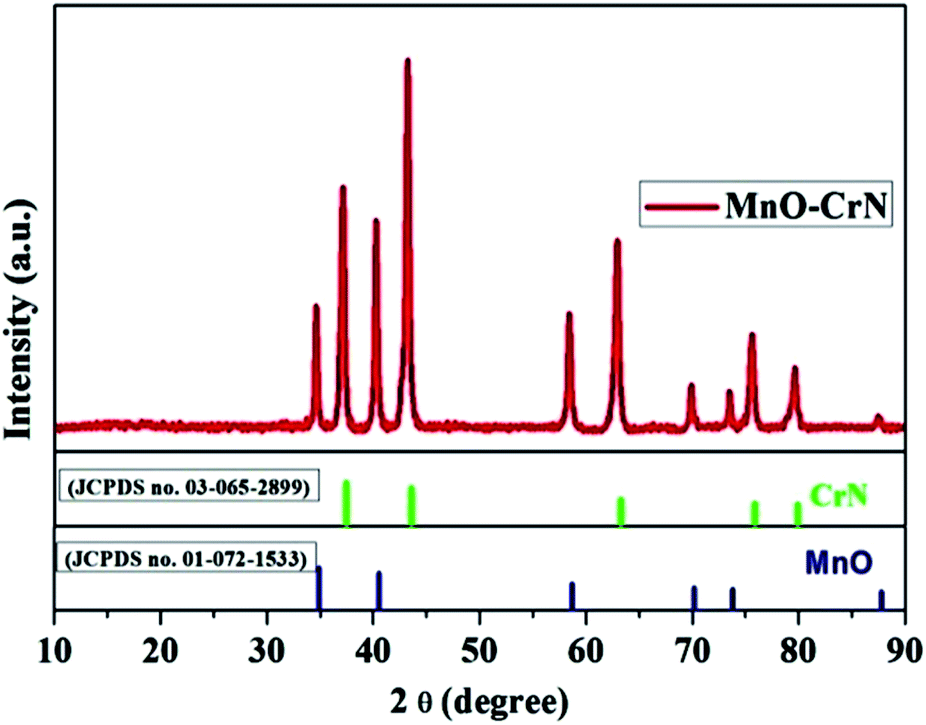
The crystallinity and phase formation of the prepared material was inspected via XRD. Fig. 1 shows the corresponding XRD pattern of the synthesized material, in which peaks emerged that can be indexed to the reflection planes of tetragonal α-MnO and cubic CrN. MnO, with the standard card number JCPDS-01-072-1533, is shown in blue, and CrN, matching the standard card number JCPDS-03-065-2899, is shown in green in Fig. 1. An additional important aspect is the morphological study and this was carried out via SEM and TEM analysis.
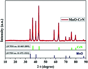 |
| | Fig. 1 The XRD pattern of the MnO–CrN composite. | |
Morphological characterization of the MnO–CrN nanocomposite
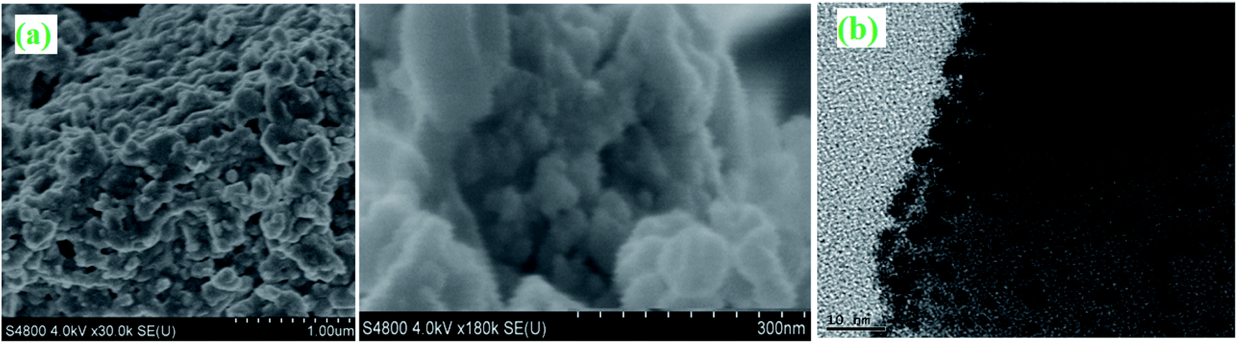
Surface morphological studies of the MnO–CrN composite nanomaterial were done via SEM and TEM, as illustrated in Fig. 2. Fig. 2(a) illustrates the existence of flake-like particles with significantly varied sizes, and rigorously aggregated particles can be seen. For more structural detail, TEM analysis was carried out, which shows that the particles are in the nano-range and maybe this is the reason they are seen to aggregate in SEM analysis; on the other hand, in TEM analysis, it can be seen that the MnO–CrN composite particles are distributed homogeneously. They have a mean size of around 5–10 nm, increasing the specific surface area of the MnO–CrN composite. It should be noted that the performance of a sensor strongly depends on the existence of nano-size material particles.
 |
| | Fig. 2 SEM (a) and TEM (b) images of the MnO–CrN composite. | |
BET specific surface area analysis
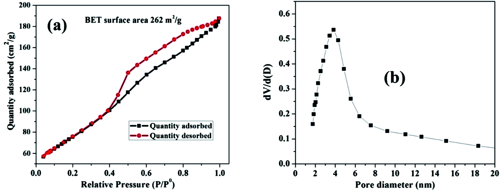
The pore size distribution and estimated surface area of the nanosized MnO–CrN composite were studied via nitrogen adsorption desorption isotherms of the as-synthesized material (Fig. 3). According to the IUPAC system of classification, the isotherms are type-IV.31 The specific surface area is found to be 262 m2 g−1.
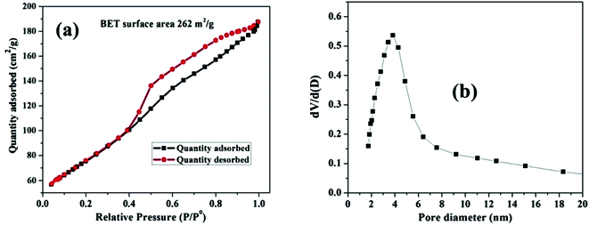 |
| | Fig. 3 (a) The N2 adsorption–desorption isotherm for the MnO–CrN nanocomposite. (b) The corresponding BJH pore size distribution curve. | |
The Barrett–Joyner–Halenda (BJH) method was applied to estimate the pore size diameter, as shown in Fig. 3(b), revealing the existence of mesopores in the composite with a diameter of around 4 nm. The synthesis of the nanosized mesoporous MnO–CrN composite will be very beneficial for sensing. Therefore, in the next step, we are going to study the application of the MnO–CrN composite to H2O2 sensing.
Electrochemical measurements
All electrochemical measurements were performed using a CHI 760C workstation, which was utilized to control the applied voltage in a three-electrode system for amperometric analysis. First of all, 5 mg ml−1 material was dispersed in a 4:1 mixture of water and isopropanol with 20 μl of Nafion, using a sonication bath for 15 min. Ink was obtained after sonication, and 3 μl of this was cast onto a 2.5 mm polished GCE. 0.1 M PBS was used as a supporting electrolyte, and it was prepared via mixing 3.39 g of NaH2PO4 and 20.20 g of Na2HPO4 in 1 L of water. An Ag/AgCl (3 M KCl) electrode and platinum wire were employed as the reference and counter electrodes, respectively. The reduction and oxidation of H2O2 on the MnO–CrN electrode were quantified via CV in 0.1 M PBS buffer (pH 7.4). Before a certain amount of H2O2 was added, the buffer was subjected to de-oxygenation with pure nitrogen for 20 min. During calibration, the surface of the sample solution was gently purged with pure nitrogen gas to generate an inert atmosphere. The electrode was subjected to electrochemical treatment via cycling the potential from −1.0 to 1.2 V at 100 mV s−1 in 0.1 M PBS until stable voltammogram curves were obtained. The detection temperature of the electrochemical cell was room temperature, i.e., 25 °C. Amperometric (i–t) analysis was carried out via the successive addition of H2O2 at −0.5 V vs. the Ag/AgCl electrode, obtained from CV curves.
Cyclic voltammetry
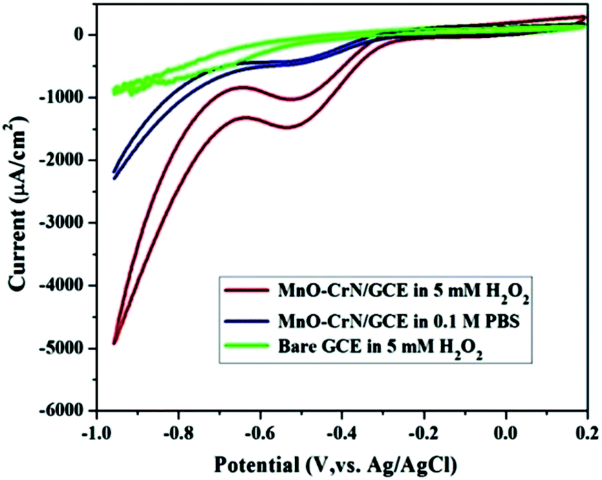
CV studies were carried out to analyze the electrocatalytic activity of the MnO–CrN composite material for the detection of H2O2. First, a bare GCE was tried for H2O2 detection in 5 mM H2O2 and negligible reduction behavior was observed. A modified glassy carbon electrode (MnO–CrN/GCE) was checked both in the presence and absence of H2O2 in 0.1 M PBS solution. A prominent reduction peak was observed when CV testing was carried out in 5 mM H2O2. Fig. 4 shows CV scans from all the above-mentioned circumstances. In the case of 5 mM (30 ml) H2O2 in 0.1 mol L−1 PBS with the modified MnO/CrN/GC electrode at 100 mV s−1 in a deoxygenated environment, a reductive current peak was seen in the range of −0.40 to −0.55 V, with the highest current obtained at −0.50 V. It is clear that the redox peaks could be assigned to electrochemical reactions involving MnO–CrN because no other interference peaks were observed from the background samples. These results indicate that the MnO–CrN composite showed excellent electrocatalytic performance for the reduction of H2O2 without being impeded in PBS matrix solution. The cathodic peak current, which is assigned to H2O2 reduction on the surface of the modified electrode, indicates that a controlled process happened during mass transfer on the electrode surface. It is clear that the reduction potential is due to MnO2 being combined with CrN. S. Lopa et al. studied pristine CrCl3 and a CrIII/II MOF, which showed a lower potential (0.4 V) than MnO2.30 Therefore, CrN transfer electrons and acts as a backbone for MnO2.
 |
| | Fig. 4 CV scans of bare and modified GCEs in a solution of 0.1 M PBS buffer (pH = 7.4) or 0.1 M PBS buffer (pH = 7.4) with 5 mM H2O2; scan rate: 100 mV s−1. | |
The amperometric response of the MnO–CrN electrode to H2O2
The performance of the synthesized MnO–CrN electrode towards H2O2 sensing was assessed through amperometric current–time (i–t) measurements after successively adding constant amounts of H2O2 into constantly stirred 0.1 M PBS solution (N2-saturated). Fig. 4 shows that the maximum current response toward the reduction of H2O2 was obtained at −0.50 V in the operating potential range of −0.45 to −0.55 V. Hence, −0.50 V was selected as the optimum reductive potential for the detection of H2O2 because the maximum reduction current is obtained at this potential.
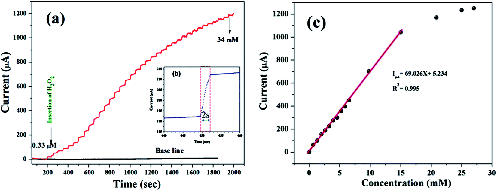
According to the representative amperometric responses shown in Fig. 5(a), after the stepwise addition of H2O2 solution a well-ordered step-like response is seen swiftly, and a steady-state signal is attained within 2 s. The respective calibration curve for H2O2 detection is illustrated in Fig. 5(b). Firstly, H2O2 was adsorbed on the MnO–CrN surface, which was reduced to a lower oxidation state due to the absorbed H2O2; secondly, the lower oxidation state of MnO–CrN was oxidized and regenerated. Sensor calibration was executed three times and standard deviations were measured. The error bars of the mean current responses were obtained based on standard deviation; as the error bars cover a very small range in comparison to the mean values, they are barely noticeable in the plot. The response was quick and reached 95% of the steady-state value in less than 2 s, and the current rose linearly with the H2O2 concentration from 0.33 μM to 15 mM. The linear regression equation between 0.33 μM and 15 mM was determined to be: I = 69.02x + 5.234 (R2 = 0.995). The linear range of MnO–CrN/GCE for H2O2 amperometric detection was found to be from 0.33 μM to 15 mM in 30 ml of PBS (R2 = 0.995) with a limit of detection (LOD) of 0.059 μM and a limit of quantification of 0.199 μM (S/N = 3).
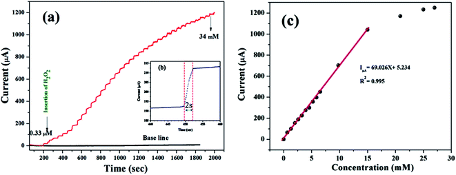 |
| | Fig. 5 (a) The amperometric responses to the successive dropwise addition of H2O2 into 0.1 M PBS (pH = 7.4) at −0.50 V (vs. Ag/AgCl) under a continuously supplied N2 atmosphere. (b) The response time of the MnO–CrN-modified GCE electrode. (c) The respective calibration curve of H2O2 concentration vs. current. | |
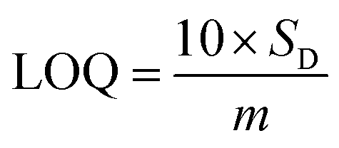
Based on linear calibration curves, the repeatability and accuracy depend on two important factors: the LOD and the LOQ (limit of quantification). Through such limits, it is possible to describe the smallest analyte concentration that can be consistently detected and quantified. The LOQ and LOD32 of MnO–CrN/GCE were calculated via applying eqn (1) and (2):
| |
 | (1) |
| |
 | (2) |
where
m is the calibration curve slope, which is measured from the regression equation, and
SD is the standard deviation from the stable signal of blank solution. The electrode performance was superior compared to different previously reported Mn-based electrodes (
Table 1). Consequently, the MnO–CrN-based modified electrode might be further used in sensors for the sensitive detection of H
2O
2 in 0.1 M PBS solution. It can be seen that the performance of the sensor is better than most other non-enzymatic H
2O
2 sensors when the MnO–CrN composite is used as an electrode. This might be associated with the higher specific surface area of the MnO–CrN composite, which offered a huge number of anchoring sites for MnO
2 deposition during the preparation of the MnO–CrN composite and prohibited the aggregation of nanosized structures.
Interference study
For practical applications, a critical property of H2O2 sensors is selectivity, which is evaluated here. Typical amperometric analysis of interference was carried out at a potential of 0.5 V via the successive injection of 0.1 mM H2O2 and 1 mM interferents, i.e., ascorbic acid, dopamine, sucrose, glucose, and uric acid, into continuously stirred N2-saturated 0.1 M PBS (pH = 7.4). Fig. 6 shows a current response to H2O2, while the other interfering species do not result in a distinct current response, which suggests satisfactory selectivity for the electrochemical detection of H2O2 when using the MnO–CrN-modified GCE.
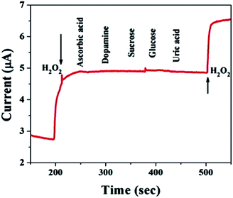 |
| | Fig. 6 A study of the response of the MnO–CrN-modified GCE to interferents with the successive addition of 0.1 mM H2O2 and 1 mM interferents, i.e., ascorbic acid, dopamine, sucrose, glucose, and uric acid, into continuously stirred N2-saturated 0.1 M PBS. Applied potential: −0.5 V; stirring rate: 400 rpm. | |
Validation of the proposed sensor
In evaluating the analytical performance of a sensor, its shelf life, reproducibility, and enduring stability are imperative. Shelf-life testing was carried out via setting aside prepared MnO–CrN/GCE in air at room temperature, followed by measurements being conducted after four weeks. It was noteworthy that the sensitivity was long-lasting, for a period of four weeks. The repeatability of MnO–CrN/GCE has also been probed via observing the CV response toward 5 mM H2O2 for 20 cycles after 4 weeks (Fig. S1†). The induced current response from MnO–CrN/GCE remains similar and stable, with the retention of the initial current value, highlighting the good shelf life. The CrN/GCE electrode displays good electrocatalytic activity in relation to the reduction of H2O2 with a LOD of 0.059 μM toward H2O2 (S/N = 3).
To calculate the recovery abilities of the MnO–CrN-composite-based sensor, standard addition techniques were applied to detect H2O2 in defatted milk. Shop-bought defatted milk samples were used. We used three samples, and the study shows good reproducibility, in the range of 99.81–98.86% (Table 2).
Table 2 Recovery tests in defatted milk samples using the MnO–CrN-nanocomposite-based sensor
| Sample |
Added (v/v) |
Found (mM l−1) |
Recovery (%) |
| 1 |
15 |
14.81 |
98.73 |
| 2 |
100 |
99.81 |
99.81 |
| 3 |
200 |
197.21 |
98.86 |
In order to determine the stability of the device, repeatability testing was carried out with a known amount of H2O2 in a defatted milk sample. Repeatability testing was carried out 100 times, as shown in Table 3, with a relative standard deviation (RSD) of 1.80% upon repeatedly measuring the H2O2 concentration in a milk sample. Hence, the sensor showed great sensitivity of 2156.25 μA mM−1 cm−2 with a wide linear range (0.33 μM to 15 mM), good selectivity for H2O2, and reproducibility in the range of 99.81–98.86% with a RSD of 1.81% and good stability.
Table 3 The repeatability of sample measurement with the MnO–CrN sensor
| Sample |
Number of measurements |
Average value (mV) |
SD (±) |
RSD (%) |
| Defatted milk sample |
100 |
1.385 |
0.025 |
1.80 |
Conclusions
In summary, we disclosed for the first time the facile synthesis of a MnO–CrN composite material, and the subsequent manufacturing of an electrode made the current work of interest. The constructed synergism between MnO–CrN/GCE and H2O2 offers increased charge-transfer effectiveness. The unique features of fabricated MnO–CrN include its well-defined size and shape. A novel non-enzymatic H2O2 sensor based on MnO–CrN is productively developed, showing an outstanding electrochemical response with high accuracy and sensitivity, and satisfactory recovery. The novelty of this work is that we combined MnO with CrN as a conduction support material, rather than with a carbon-based material, and synthesized such a material for the first time at the nano-level via a new facile synthesis method. Here, CrN might be playing the role of a conducting material, which is the reason why the MnO–CrN composite is highly competent as a non-enzymatic electrochemical sensing material for H2O2. An assessment of the H2O2 sensing activity of MnO–CrN/GCE concludes that MnO–CrN/GCE has scope for future development due to its suitable LOD (0.059 μM) and sensitivity (2156.25 μA mM−1 cm−2).
Conflicts of interest
All authors made equal contributions, and there are no conflicts of interest.
References
- T. Finkel and N. J. Holbrook, Oxidants, oxidative stress and the biology of ageing, Nature, 2000, 408, 239 CrossRef CAS PubMed.
- B. Halliwell and J. M. Gutteridge, Free radicals in biology and medicine, Oxford University Press, USA, 2015 Search PubMed.
- M. P. Murphy, et al., Unraveling the biological roles of reactive oxygen species, Cell Metab., 2011, 13, 361–366 CrossRef CAS PubMed.
- W. M. Nauseef, How human neutrophils kill and degrade microbes: an integrated view, Immunol. Rev., 2007, 219, 88–102 CrossRef CAS PubMed.
- J. R. Stone and S. Yang, Hydrogen peroxide: a signaling messenger, Antioxid. Redox Signaling, 2006, 8, 243–270 CrossRef CAS PubMed.
- C. C. Winterbourn, in Methods in enzymology, Elsevier, 2013, vol. 528, pp. 3–25 Search PubMed.
- C. C. Winterbourn, Reconciling the chemistry and biology of reactive oxygen species, Nat. Chem. Biol., 2008, 4, 278 CrossRef CAS PubMed.
- R. Gaikwad, P. R. Thangaraj and A. K. Sen, Direct and rapid measurement of hydrogen peroxide in human blood using a microfluidic device, Sci. Rep., 2021, 11, 2960, DOI:10.1038/s41598-021-82623-4.
- S. Chen, R. Yuan, Y. Chai and F. Hu, Electrochemical sensing of hydrogen peroxide using metal nanoparticles: a review, Microchim. Acta, 2013, 180, 15–32 CrossRef CAS.
- W. Chen, S. Cai, Q.-Q. Ren, W. Wen and Y.-D. Zhao, Recent advances in electrochemical sensing for hydrogen peroxide: a review, Analyst, 2012, 137, 49–58 RSC.
- H. S. Marinho, L. Cyrne, E. Cadenas and F. Antunes, The cellular steady-state of H2O2: latency concepts and gradients, Methods Enzymol., 2013, 527, 3–19 CAS.
- N. Lu, et al., Yolk–shell nanostructured Fe3O4@C magnetic nanoparticles with enhanced peroxidase-like activity for label-free colorimetric detection of H2O2 and glucose, Nanoscale, 2017, 9, 4508–4515 RSC.
- V. Patel, M. Kelleher and M. McGurk, Clinical use of hydrogen peroxide in surgery and dentistry–why is there a safety issue?, Br. Dent. J., 2010, 208, 61 CrossRef CAS PubMed.
- Q. Chen, et al., Pharmacologic ascorbic acid concentrations selectively kill cancer cells: action as a pro-drug to deliver hydrogen peroxide to tissues, Proc. Natl. Acad. Sci. U. S. A., 2005, 102, 13604–13609 CrossRef CAS PubMed.
- M. Somasundrum, K. Kirtikara and M. Tanticharoen, Amperometric determination of hydrogen peroxide by direct and catalytic reduction at a copper electrode, Anal. Chim. Acta, 1996, 319, 59–70 CrossRef CAS.
- E. Preisler, Semiconductor properties of manganese dioxide, J. Appl. Electrochem., 1976, 6, 311–320 CrossRef CAS.
- C. Hu, D. Liu, Y. Xiao and L. Dai, Functionalization of graphene materials by heteroatom-doping for energy conversion and storage, Prog. Nat. Sci.: Mater. Int., 2018, 28(2), 121–132 CrossRef CAS.
- Y. Song, K. Cui, L. Wang and S. Chen, The electrodeposition of Ag nanoparticles on a type I collagen-modified glassy carbon electrode and their applications as a hydrogen peroxide sensor, Nanotechnology, 2009, 20, 105501 CrossRef PubMed.
- K. Cui, Y. Song, Y. Yao, Z. Huang and L. Wang, A novel hydrogen peroxide sensor based on Ag nanoparticles electrodeposited on DNA-networks modified glassy carbon electrode, Electrochem. Commun., 2008, 10, 663–667 CrossRef CAS.
- B. Xu, M.-L. Ye, Y.-X. Yu and W.-D. Zhang, A highly sensitive hydrogen peroxide amperometric sensor based on MnO2-modified vertically aligned multiwalled carbon nanotubes, Anal. Chim. Acta, 2010, 674, 20–26 CrossRef CAS PubMed.
- W. Bai, X. Zhang, S. Zhang, Q. Sheng and J. Zheng, Acidification of manganese dioxide for ultrasensitive electrochemical sensing of hydrogen peroxide in living cells, Sens. Actuators, B, 2017, 242, 718–727 CrossRef CAS.
- H.-L. Xu and W.-D. Zhang, Graphene oxide–MnO2 nanocomposite-modified glassy carbon electrode as an efficient sensor for H2O2, Chin. Chem. Lett., 2017, 28, 143–148 CrossRef CAS.
- L. Zhang, Z. Fang, Y. Ni and G. Zhao, Direct electrocatalytic oxidation of hydrogen peroxide based on Nafion and microspheres MnO2 modified glass carbon electrode, Int. J. Electrochem. Sci., 2009, 4, 407–413 CAS.
- Y. Han, J. Zheng and S. Dong, A novel nonenzymatic hydrogen peroxide sensor based on Ag–MnO2–MWCNTs nanocomposites, Electrochim. Acta, 2013, 90, 35–43 CrossRef CAS.
- S. B. Hocevar, B. Ogorevc, K. Schachl and K. Kalcher, Glucose microbiosensor based on MnO2 and glucose oxidase modified carbon fiber microelectrode, Electroanalysis, 2004, 16, 1711–1716 CrossRef CAS.
- P. Zhang, D. Guo and Q. Li, Manganese oxide ultrathin nanosheets sensors for non-enzymatic detection of H2O2, Mater. Lett., 2014, 125, 202–205 CrossRef CAS.
- X. Xiao, et al., Electrospun carbon nanofibers with manganese dioxide nanoparticles for nonenzymatic hydrogen peroxide sensing, J. Mater. Sci., 2013, 48, 4843–4850 CrossRef CAS.
- L. Li, et al., A novel nonenzymatic hydrogen peroxide sensor based on MnO2/graphene oxide nanocomposite, Talanta, 2010, 82, 1637–1641 CrossRef CAS PubMed.
- M. Lin and T. Tseng, Chromium (III) hexacyanoferrate (II)-based chemical sensor for the cathodic determination of hydrogen peroxide, Analyst, 1998, 123, 159–163 RSC.
- N. S. Lopa, et al., A base-stable metal-organic framework for sensitive and non-enzymatic electrochemical detection of hydrogen peroxide, Electrochim. Acta, 2018, 274, 49–56 CrossRef CAS.
- K. Sing, The use of nitrogen adsorption for the characterisation of porous materials, Colloids Surf., A, 2001, 187, 3–9 CrossRef.
- D. A. Armbruster and T. Pry, Limit of Blank, Limit of Detection and Limit of Quantitation, Clin. Biochem. Rev., 2008, 29, S49–S52 Search PubMed.
Footnote |
| † Electronic supplementary information (ESI) available. See DOI: 10.1039/d1ra01485d |
|
| This journal is © The Royal Society of Chemistry 2021 |
Click here to see how this site uses Cookies. View our privacy policy here. 
 Open Access Article
 This Open Access Article is licensed under a
  ab,
Karim Khan
ab,
Karim Khan