 Open Access Article
Harnessing reversible dry adhesion using shape memory polymer microparticles
Wenbing Li *,
Junhao Liu,
Wanting Wei and
Kun Qian
Key Laboratory of Eco-Textiles, Ministry of Education, Jiangnan University, Wuxi 214122, PR China. E-mail: wenbingli@jiangnan.edu.cn
First published on 1st June 2021
Abstract
Reversible adhesion switching on the micron scale greatly extends the functionality of shape memory polymers. Herein, we report the first usage of polystyrene microparticles for the reversible dry adhesive of the on/off switch between bonding and debonding. The reversible dry adhesive property is attributed to the stiffness change under the varying temperature of the polystyrene microparticle, as well as its ability to lock a temporary shape and recover to its original shape. The decrease in the modulus/viscosity of polystyrene microparticles at high temperature improves the surface wetting/contact and enhances the adhesive bond by contact pressure. Then, when heating above its glass transition temperature after bonding, the adhesive recovers to its initial shape, resulting in almost a zero adhesion strength. Besides, adhesion tests reveal that the magnitude of adhesion variations depends on substrates, contact pressures, and particle sizes. Therefore, as a thermotropic-induced shape memory material, the adhesive (polystyrene microparticles) can be used to create joints and can be heated to achieve its own restoration.
1. Introduction
In nature, many small animals have exhibited reversible dry adhesion.1–3 The unique reversible adhesion ability of gecko, fly, and spider has attracted tremendous scientific interests from researchers in different fields.4–11 In recent years, material researchers have focused on mimicking the structure of biological adhesives to fabricate bioinspired structured surfaces for “smart” adhesives.12–16 This kind of adhesive has a wide range of applications in automotive assembly,17 removable prosthetics,18 and transfer printing.19 It is known that geckos detach their footpads through mechanical toe actions.20,21 But the debonding of most synthetic adhesives inspired by the fibrillar arrays of gecko footpads is induced by external peeling forces. Namely, the synthetic gecko-inspired adhesives are not self-reversible such as geckos in the process of multiple bonding–debonding cycles.22–25 Another limitation is that the current production strategy is mainly based on lithography22,23 or soft lithography,26,27 in which there are problems in the production efficiency and scalability of these materials. In order to successfully adopt these materials as “smart” adhesives, these two limitations must be overcome.Shape memory polymers (SMPs) are stimuli-responsive materials that can recover to their initial shapes from deformed temporary shapes when exposed to appropriate stimulus.28–31 This remarkable capability allows SMPs to serve as excellent candidates for reversible smart adhesives,32–35 especially microstructured SMP surfaces.8,12,15,36 Generally, SMPs depend on a thermal transition, such as glass transition (Tg) or melt transition (Tm), which induces a large change in the storage modulus and thus allows the internal stress to be released from previous deformation. Consequently, the material changes its shape and recovers to its original processed shape.37–40 Since the softened material contributes to surface wetting and contact, this significant modulus change can also be used for adhesion and causes a rigid mechanical bonding upon subsequent cooling.32 When the temperature is higher than the thermal transition temperature again, the adhesive film will weaken, leading to debonding.
In this work, we present a novel design strategy for a self-peeling reversible dry adhesive system that uses shape memory polystyrene (SMPS) microparticles as adhesion units to control the adhesive properties. The attachment–detachment cycles are based on the shape fixation and shape recovery of SMPS microparticles. The adhesive properties of the proposed “smart” adhesive are controlled by the particle numbers, and the reversible adhesion is based on heat-triggered “self-peeling” that is inspired by the mechanical moves of gecko toes.20,21 Our concept and method in this paper have several advantages over prior methods including: (i) easy control of adhesion offered by the SMPS microparticles, (ii) simplicity and convenience in the operation method without expensive micro-fabrication for patterning, and (iii) suitability for a variety of polymer systems.
2. Experimental section
Materials
SMPS particles with diameters 30 μm and 200 μm and 2% crosslinking density were purchased from Sigma-Aldrich. The ethyl alcohol and acetone were obtained from Sigma-Aldrich, too.Preparation
Before the thermal embossing nanoimprint lithography (TE-NIL) process, the silicon wafers and aluminum sheets used for depositing particles were successively cleaned by ethyl alcohol, acetone and deionized water. Secondly, the aqueous solution containing SMPS particles was dripped through a dropper onto the silicon wafer and aluminum sheet surfaces. Thirdly, the silicon wafers and aluminum sheets with the SMPS aqueous solution were dried for 24 hours at room temperature. At last, when the deionized water evaporated completely, desiccative particles that were dispersed on the surfaces of silicon wafer and aluminum sheet were obtained for the following adhesion experiment.Bonding–debonding of microparticles
All TE-NIL procedures were executed through a nanoimprinter (Eitre 3, Obducat). The condition (140 °C, 4 MPa, 15 minutes) was used for the 30 μm SMPS particles, and the 200 μm particles were processed at 140 °C under 0.7 MPa pressure for 15 minutes. In the TE-NIL process, the 200 μm SMPS particles would be crushed under 4 MPa pressure due to large particle deformation. Therefore, the pressure was reduced to 0.7 MPa for 200 μm particles as adjustment. TE-NIL is a dependable preparation method that is able to compress two parallel rigid sheets using different pressures.41–43 The bonding and debonding using SMPS microparticles by the TE-NIL process are schematized in Fig. 1. Firstly, the SMPS microparticles were deposited on the silicon and aluminum surfaces via drip-coating. Secondly, the particles were imprinted with a corresponding flat silicon wafer or aluminum sheet mold under a pre-set pressure at 140 °C. Finally, the temperature was cooled to room temperature, while the pressure remained constant. Then the pressure was released; the temporary disc-like shape could be fixed, and the two silicon wafers or aluminum sheets were bonded by the flattened particles. To reverse the adhesion, the SMPS microparticles were re-heated above their glass transition temperatures (Tgs), which caused debonding due to shape recovery. For the adhesion tests, the bonded silicon wafers or aluminum sheets were debonded using a universal testing machine to determine the adhesive forces.Characterization methods
Field emission scanning electron microscopy (FE-SEM, JSM-7401F, JEOL Ltd., Japan) was used to characterize the morphologies of deformed SMPS microparticles. For the adhesion samples, a room-temperature static tensile test was completed using a universal testing machine (Instron 5965, Instron Co., USA) at a cross-head speed of 3 mm min−1.Image processing
The areas of flattened SMPS microparticles were measured after image post-processing by ImageJ software. In detail, original SEM images of the SMPS particles were opened using ImageJ. The areas of the flattened SMPS particles after temporary shape fixing can be measured based on the distance in the pixels of the known scale length.3. Results and discussion
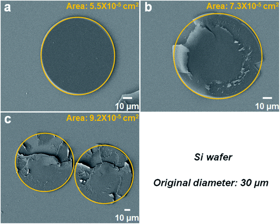
As previously reported, SMPS microparticles (Tg ∼ 100 °C) exhibit very reliable shape memory effect.42 In this study, two kinds of SMPS particles with different diameters (30 μm and 200 μm, respectively) were investigated. Taking the 30 μm SMPS particle as an example, the large modulus change of SMPS microparticle is the basis for designing reversible dry adhesive through programming a temporary shape and recovering to the permanent shape (shown in Fig. 2). Scanning electron microscopy (SEM) images showed that the flattened SMPS microparticle (Fig. 2a) could recover to its permanent shape (Fig. 2b) when the deformed microparticle was heated at 140 °C for 1 h. Fig. 3 shows top-view images of the deformed SMPS particles with the initial diameter of 30 μm. All the deformed particles are in close contact with the two silicon wafers on both sides. Because the number of dispersed SMPS particles (Fig. 3a: 183 particles, Fig. 3b: 42 particles, Fig. 3c: 19 particles) is different on the silicon substrates, the adhesion areas of the deformed flattened SMPS particles are different in the same condition (140 °C, 4 MPa, 15 minutes). From the SEM images Fig. 3a, b and c, we can figure out the areas of the deformed SMPS particles are 5.5 × 10⁻⁵ cm2, 7.3 × 10⁻⁵ cm2 and 9.2 × 10⁻⁵ cm2, respectively. In addition, the adhesive particles (shown in Fig. 3b and c) are torn using a universal testing machine when the adhesive force is tested. Herein, the tear of deformed particles is due to the relatively large adhesion area and excellent bonding properties between particles and wafers.12,32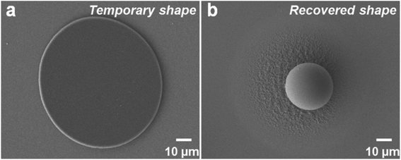 | ||
| Fig. 2 SEM images showing the SMPS particles with 30 μm diameter after (a) compression, and (b) shape recovery. | ||
The test method of the adhesive force of the bonded SMPS microparticles to two silicon wafers or aluminum sheets is demonstrated in Fig. 4. First, two locking type nylon cable tie belts are cut into appropriate length, and then, a hole is cut in each belt. Second, the nonbonded face (back-side) of the two substrates (silicon wafers or aluminum sheets) with the dimensions of 10 × 10 mm are respectively glued to two holed locking type nylon cable tie belts. Third, the two holed locking type nylon cable tie belts are respectively tied together with the other two holed nylon cable tie belts using two nylon ropes. Finally, the home-made adhesive system was put into a universal testing machine to obtain the desired adhesive data.
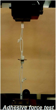 | ||
| Fig. 4 Test method of adhesive performance of the SMPS microparticles using a universal testing machine. | ||
According to the above-mentioned adhesive force test method, the adhesive properties can be quantified. We performed tests using the 30 μm SMPS microparticle samples with different number of particles, and the results are shown in Fig. 5. From Fig. 5a, b and c, the maximum tensile stresses (adhesive forces) of the three SMPS adhesives are, respectively, 1.31 N, 0.33 N and 0.17 N, while the corresponding numbers of the SMPS microparticles between two silicon wafers are 183, 42 and 19. Herein, the adhesive force decreases with the decreasing of bonding particle numbers, because of the reduction of total adhesion area of the bonded SMPS microparticles to the substrates. On the basis of the adhesion area of a single deformed SMPS microparticle calculated in Fig. 3 and the known number of particles, the total adhesion areas of 1.0 × 10⁻² cm2, 3.1 × 10⁻³ cm2 and 1.7 × 10⁻³ cm2 are calculated, which respectively corresponds to the three adhesive systems in Fig. 5a, b and c. To determine the adhesive performance of the SMPS adhesive, the adhesive strengths of the adhesive were calculated using the ratio of the adhesive forces to the total adhesion areas of the bonded particles. The adhesive strengths of the three SMPS microparticle adhesives shown in Fig. 5a–c are 131 N cm−2, 106 N cm−2 and 100 N cm−2. The average adhesive strength of the SMPS microparticle adhesives is 112.3 N cm−2, superior to other reported biomimetic fibrillar dry adhesives with adhesion strengths ranging from 0.1 N cm−2 to 100 N cm−2.44,45 Compared to the carbon nanotube adhesive with the adhesive strength of only about 4 N cm−2,46 the adhesive strength of the SMPS microparticle adhesive is unusually high. To reverse the adhesion, the SMPS microparticles were heated to 140 °C to recover to their permanent shapes. The adhesive force was too low that our equipment cannot accurately measure it, and thus, it can be regarded as nearly zero. At this point, the substrate can easily lift away from the SMPS microparticle surfaces, as previously reported.12
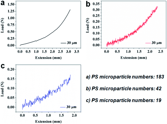 | ||
| Fig. 5 Demonstration of adhesive performance for the 30 μm SMPS microparticles with different particle numbers using the Si wafers. (a) 183 particles. (b) 42 particles. (c) 19 particles. | ||
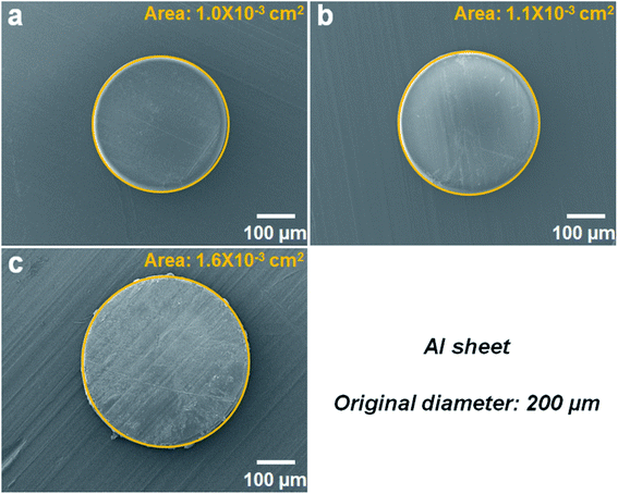
In order to further demonstrate the usefulness of this adhesive, we investigate its performance in bonding other types of substrate. The adhesive force tests using two aluminum sheets are carried out. In this system, the 200 μm SMPS microparticles are used, and the adhesion test is performed under another bonding condition (140 °C, 0.7 MPa, 15 minutes). For this sample, three groups of 200 μm SMPS microparticles with different particle numbers are placed on the top surface of the bottom substrate. As can be seen in the SEM images in Fig. 6, since the number of the SMPS microparticles varies, the adhesion areas of the flattened particles bonding two aluminum sheets are also different under the same pressure (0.7 MPa). Using the ImageJ software, the calculated areas of the single deformed SMPS microparticles in Fig. 6a, b and c are 1.0 × 10⁻³ cm2, 1.1 × 10⁻³ cm2 and 1.6 × 10⁻³ cm2, respectively.
With the single particle area (Fig. 6a–c), the tested adhesive forces (Fig. 7a–c) and the known particle number (Fig. 7a: 171 particles, Fig. 7b: 122 particles, Fig. 7c: 76 particles), we can calculate the total adhesion area and investigate the adhesion capability. From Fig. 7a, b and c, the maximum adhesive forces are, respectively, 0.21 N, 0.15 N and 0.15 N, and the total adhesion areas are, respectively, 0.17 cm2, 0.13 cm2 and 0.12 cm2. Thus, the adhesive strengths of the three groups of the 200 μm SMPS microparticle adhesives are 1.24 N cm−2, 1.15 N cm−2 and 1.25 N cm−2, respectively. Compared with the 30 μm SMPS microparticle adhesive, the average adhesive strength (1.21 N cm−2) of the 200 μm SMPS microparticle adhesive is remarkably low. Though the interfacial force is negligible in the bulk shape memory effect, interfacial force becomes more and more dominant as the particle size decreases.47 The adhesive strength also depends on the contact pressure during bonding and the stimulation time of bonding. A possible explanation for this disparity is that the higher contact pressure of the 30 μm SMPS microparticles is beneficial to improve adhesive strength relative to the 200 μm SMPS microparticles.33 Therefore, the contact pressure plays an important role in the adhesive capacity of the particles to different substrates.
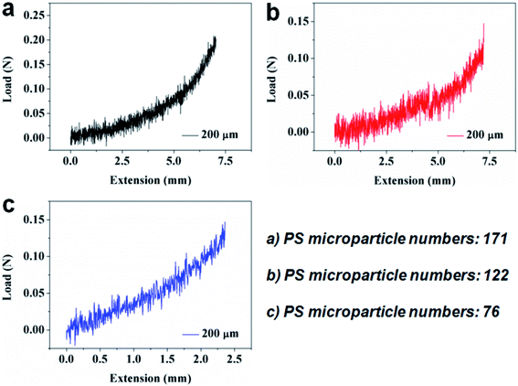 | ||
| Fig. 7 Demonstration of adhesive performance for the 200 μm SMPS microparticles with different particle numbers using the Al sheets. (a) 171 particles. (b) 122 particles. (c) 76 particles. | ||
By using the shape memory property of the polystyrene microparticle, a switchable microparticle adhesive was realized. To the best of our knowledge, this is the first demonstration of shape memory microparticles in the field of reversible dry adhesives. This study shows that the shape memory effect is not only effective at the micro-scale, but also can be well applied to switchable adhesions. The demonstrated adhesive ability indicates that SMPS microparticles have a good potential in applications requiring a temporary adhesion or an on/off switch for the adhesion. For instance, its unique structural stiffness, superior mechanical properties, good machining performance and strong reversible adhesion to silicon wafer suggests potential purposes for the packaging of electronics and the gluing of glass components. Furthermore, this type of reversible adhesion allows the assembled structures to be easily self-detachable for maintenance or recycling. This principle is not only applicable to the SMPS microparticle, but can also be extended to other material systems that exhibit thermoresponsive shape memory behavior.
4. Conclusions
In summary, SMPs can provide excellent bonding property because of their shape memory effects and variable moduli under temperature changes. This paper proposes an adhesive unit based on polystyrene microparticle (30 μm or 200 μm in diameter) that is capable of repeatable smart adhesion and exhibits reversible adhesion under heating. The pull-off adhesive strength of our unique polystyrene microparticle adhesive to silicon wafers can reach above 100 N cm−2, far exceeding that of most other reusable macro-scale dry adhesives. When detachment is required, the adhesive force can be reduced to negligible levels after heating. Compared with the current reversible adhesives, our adhesive system has many advantages, such as low cost of raw materials, simple using method, strong adhesive strength, facile adhesion elimination on demand, excellent mechanical performances and good reusability. Overall, we believe that the ability of this reversible dry adhesive is useful not only for further study into responsive material-based dry adhesives with reversible adhesion switching and self-detaching, but also for a broad range of applications in electronic packaging, biomedical devices and household products.Conflicts of interest
The authors declare no competing financial interest.Acknowledgements
We acknowledge the funding support from the Fundamental Research Funds for the Central Universities (JUSRP12031), and the Innovation/Entrepreneurship Program of Jiangsu Province ([2020] 30822). The authors also thank Dr Mengyuan Wang and Yinan Lu for supporting in the material characterization.References
- K. Autumn, Y. A. Liang, S. T. Hsieh, W. Zesch, W. P. Chan, T. W. Kenny, R. Fearing and R. J. Full, Nature, 2000, 405, 681–685 CrossRef CAS PubMed.
- E. Arzt, S. Gorb and R. Spolenak, Proc. Natl. Acad. Sci. U. S. A., 2003, 100, 10603–10606 CrossRef CAS PubMed.
- T. Eisner and D. J. Aneshansley, Proc. Natl. Acad. Sci. U. S. A., 2000, 97, 6568–6573 CrossRef CAS PubMed.
- K. Autumn and A. M. Peattie, Integr. Comp. Biol., 2002, 42, 1081–1090 CrossRef PubMed.
- G. Huber, H. Mantz, R. Spolenak, K. Mecke, K. Jacobs, S. N. Gorb and E. Arzt, Proc. Natl. Acad. Sci. U. S. A., 2005, 102, 16293–16296 CrossRef CAS PubMed.
- M. P. Murphy, S. Kim and M. Sitti, ACS Appl. Mater. Interfaces, 2009, 1, 849–855 CrossRef CAS PubMed.
- M. J. Hancock, K. Sekeroglu and M. C. Demirel, Adv. Funct. Mater., 2012, 22, 2223–2234 CrossRef CAS PubMed.
- S. Kim, M. Sitti, T. Xie and X. C. Xia, Soft Matter, 2009, 5, 3689–3693 RSC.
- Y. Cho, G. Kim, Y. Cho, S. Y. Lee, H. Minsky, K. T. Turner, D. S. Gianola and S. Yang, Adv. Mater., 2015, 27, 7788–7793 CrossRef CAS PubMed.
- Y. Cho, H. K. Minsky, Y. Jiang, K. Yin, K. T. Turner and S. Yang, ACS Appl. Mater. Interfaces, 2018, 10, 11391–11397 CrossRef CAS PubMed.
- N. J. Glassmaker, A. Jagota, C. Y. Hui, W. L. Noderer and M. K. Chaudhury, Proc. Natl. Acad. Sci. U. S. A., 2007, 104, 10786–10791 CrossRef CAS PubMed.
- J. D. Eisenhaure, T. Xie, S. Varghese and S. Kim, ACS Appl. Mater. Interfaces, 2013, 5, 7714–7717 CrossRef CAS PubMed.
- S. A. Turner, J. Zhou, S. S. Sheiko and V. S. Ashby, ACS Appl. Mater. Interfaces, 2014, 6, 8017–8021 CrossRef CAS PubMed.
- R. Wang and T. Xie, Langmuir, 2010, 26, 2999–3002 CrossRef CAS PubMed.
- Y. Wang and J. Xiao, Soft Matter, 2017, 13, 5317–5323 RSC.
- R. Hensel, K. Moh and E. Arzt, Adv. Funct. Mater., 2018, 28, 1800865 CrossRef.
- D. D. Rodrigues, P. H. Winfield and D. Morrey, Mater. Sci. Forum, 2013, 765, 766–770 Search PubMed.
- M. L. B. Palacio, B. Bhushan and S. R. Schricker, Mater. Lett., 2013, 92, 409–412 CrossRef CAS.
- S. Kim, J. Wu, A. Carlson, S. H. Jin, A. Kovalsky, P. Glass, Z. Liu, N. Ahmed, S. L. Elgan, W. Chen, P. M. Ferreira, M. Sitti, Y. Huang and J. A. Rogers, Proc. Natl. Acad. Sci. U. S. A., 2010, 107, 17095–17100 CrossRef CAS PubMed.
- K. Autumn, A. Dittmore, D. Santos, M. Spenko and M. Cutkosky, J. Exp. Biol., 2006, 209, 3569–3579 CrossRef CAS PubMed.
- Y. Tian, N. Pesika, H. Zeng, K. Rosenberg, B. Zhao, P. McGuiggan, K. Autumn and J. Israelachvili, Proc. Natl. Acad. Sci. U. S. A., 2006, 103, 19320–19325 CrossRef CAS PubMed.
- A. K. Geim, S. V. Dubonos, I. V. Grigorieva, K. S. Novoselov, A. A. Zhukov and S. Y. Shapoval, Nat. Mater., 2003, 2, 461–463 CrossRef CAS PubMed.
- H. Lee, B. P. Lee and P. B. Messersmith, Nature, 2007, 448, 338–341 CrossRef CAS PubMed.
- L. Ge, S. Sethi, L. Ci, P. M. Ajayan and A. Dhinojwala, Proc. Natl. Acad. Sci. U. S. A., 2007, 104, 10792–10795 CrossRef CAS PubMed.
- M. Lamblet, E. Verneuil, T. Vilmin, A. Buguin, P. Silberzan and L. Leger, Langmuir, 2007, 23, 6966–6974 CrossRef CAS PubMed.
- J. Iturri, L. J. Xue, M. Kappl, L. Garcia-Fernandez, W. J. P. Barnes, H. J. Butt and A. del Campo, Adv. Funct. Mater., 2015, 25, 1499–1505 CrossRef CAS.
- H. E. Jeong and K. Y. Suh, Nano Today, 2009, 4, 335–346 CrossRef CAS.
- Q. Zhao, H. J. Qi and T. Xie, Prog. Polym. Sci., 2015, 49–50, 79–120 CrossRef CAS.
- J. S. Leng, X. Lan, Y. J. Liu and S. Y. Du, Prog. Mater. Sci., 2011, 56, 1077–1135 CrossRef CAS.
- W. B. Li, Y. J. Liu and J. S. Leng, J. Mater. Chem. A, 2015, 3, 24532–24539 RSC.
- W. Li, Y. Liu and J. Leng, ACS Appl. Mater. Interfaces, 2017, 9, 44792–44798 CrossRef CAS PubMed.
- T. Xie and X. C. Xiao, Chem. Mater., 2008, 20, 2866–2868 CrossRef CAS.
- B. T. Michal, E. J. Spencer and S. J. Rowan, ACS Appl. Mater. Interfaces, 2016, 8, 11041–11049 CrossRef CAS PubMed.
- R. Wang, X. Xiao and T. Xie, Macromol. Rapid Commun., 2010, 31, 295–299 CrossRef CAS PubMed.
- X. F. Luo, K. E. Lauber and P. T. Mather, Polymer, 2010, 51, 1169–1175 CrossRef CAS.
- C. M. Chen, C. L. Chiang, C. L. Lai, T. Xie and S. Yang, Adv. Funct. Mater., 2013, 23, 3813–3823 CrossRef CAS.
- A. Lendlein and S. Kelch, Angew. Chem., Int. Ed., 2002, 41, 2034–2057 CrossRef CAS.
- J. L. Hu, Y. Zhu, H. H. Huang and J. Lu, Prog. Polym. Sci., 2012, 37, 1720–1763 CrossRef CAS.
- C. Liu, H. Qin and P. T. Mather, J. Mater. Chem., 2007, 17, 1543–1558 RSC.
- X. Zheng, S. Zhou, X. Li and J. Weng, Biomaterials, 2006, 27, 4288–4295 CrossRef CAS PubMed.
- Z. Wang, C. Hansen, Q. Ge, S. H. Maruf, D. U. Ahn, H. J. Qi and Y. Ding, Adv. Mater., 2011, 23, 3669–3673 CrossRef CAS PubMed.
- L. M. Cox, J. P. Killgore, Z. Li, Z. Zhang, D. C. Hurley, J. Xiao and Y. Ding, Adv. Mater., 2014, 26, 899–904 CrossRef CAS PubMed.
- L. M. Cox, X. Sun, C. Wang, N. Sowan, J. P. Killgore, R. Long, H. A. Wu, C. N. Bowman and Y. Ding, ACS Appl. Mater. Interfaces, 2017, 9, 14422–14428 CrossRef CAS PubMed.
- S. Hu and Z. Xia, Small, 2012, 8, 2464–2468 CrossRef CAS PubMed.
- D. Sameoto and C. Menon, Smart Mater. Struct., 2010, 19, 103001 CrossRef.
- C. T. Wirth, S. Hofmann and J. Robertson, Diamond Relat. Mater., 2008, 17, 1518–1524 CrossRef CAS.
- L. M. Cox, J. P. Killgore, Z. Li, R. Long, A. W. Sanders, J. Xiao and Y. Ding, Langmuir, 2016, 32, 3691–3698 CrossRef CAS PubMed.
| This journal is © The Royal Society of Chemistry 2021 |


