 Open Access Article
Novel piperidinium-based ionic liquid as electrolyte additive for high voltage lithium-ion batteries
Wenlin Zhang,
Qingcha Ma,
Xuejiao Liu,
Shuangcheng Yang and
Fengshou Yu *
*
National-Local Joint Engineering Laboratory for Energy Conservation in Chemical Process Integration and Resources Utilization, School of Chemical Engineering and Technology, Hebei University of Technology, Tianjin, China. E-mail: yfsh@hebut.edu.cn
First published on 22nd April 2021
Abstract
Conventional carbonate-based electrolyte is prone to oxidative decomposition at high voltage (over 4.5 V vs. Li/Li+), which leads to the bad oxidation stability and inferior cycling performance of lithium ion batteries (LIBs). To solve these problems, a novel ionic liquid (IL) N-butyronitrile-N-methylpiperidinium bis(fluorosulfonyl)imide (PP1,CNFSI) was synthesized and explored as the additive to the LiPF6–ethylene carbonate (EC)/dimethyl carbonate (DMC) electrolyte. For the cell performance, the addition of PP1,CNFSI not only inhibits overcharge phenomenon, but also improves discharge capacity, thus enhancing capacity retention capability. Compared to the cell with blank electrolyte, the capacity retentions of adding 15 wt% PP1,CNFSI into the electrolyte were improved to 96.8% and 97% from 82.8% and 78.7% at 0.2 C and 5 C, respectively. The effects of PP1,CNFSI on the LNMO cathode surface were further investigated by electrochemical impedance spectroscopy (EIS), scanning electron microscopy (SEM), transmission electron microscopy (TEM) and X-ray photoelectron spectroscopy (XPS). It reveals that PP1,CNFSI addition drives the formation of solid electrolyte interphase (SEI) film which suppresses oxidative decomposition of the electrolyte and protects the structure cathode material.
1. Introduction
Lithium-ion batteries (LIBs) possessing high energy density, large specific capacity, and excellent cycle stability have been considered to be efficient and environment-friendly energy storage systems.1–5 However, the development of LIBs with higher energy density accomplished by the cathode materials e.g. LiNi0.5Mn1.5O4 (LNMO) characterizing high working voltage is still a challenge.6–9 The cathode material of LNMO is attractive because of its high working voltage up to 5.0 V and good cycle life.10–13 However, the high operation voltage induces substantial oxidative decomposition of the conventional electrolytes resulting in rapid capacity fading.14,15 Meanwhile, LiPF6, the supplement of Li+, is easily hydrolyzed by trace amounts of H2O giving HF acid which causes the damage of LNMO cathode.16 These undesirable reactions scarify battery cycling life17 and therefore the reliability of electrolytes need to be improved to match the increased working voltage of cathode.18The extensive attentions have been attracted to develop functional solvents or additives to broaden the operation window of electrolytes to enhance the performance of LIBs at high voltage.19 The former was to adopt some oxidation resistant solvents supporting high operating voltage.16 However, some issues such as the decrease of electrical conductivity and increase of viscosity are also introduced.20
Thus, the development of a suitable electrolyte additive such as phenyl trifluoromethyl sulfide (PTS) and ionic liquids (ILs) has drawn much attention in order to expand the electrochemical operation windows and improve the cell performance.21–23
ILs have been used as promising electrolyte additives in the high voltage LIBs due to the advantages of thermal stability, non-flammability and large electrochemical window.24–28 Piperidinium-based ILs are gradually used as electrolyte additives in LIBs due to high conductivity and wide electrochemical window. Dong, et al. have revealed that a piperidium-based IL is used in high voltage and temperature conditions, the addition of IL results in the formation of a protective cathode film inhibiting severe decomposition of electrolytes.29 The modification on ILs can be focused on both cations and anions. The functionalization of cation is achieved by introducing functional groups. The nitrile group (–CN) can react with water in the electrolyte to lower the content of water in the electrolyte, which reduces the decomposition of the electrolyte and stabilize the electrode/electrolyte interface.30,31 Zhang et al. reported a nitrile-functional IL as the high voltage additive to form a stable film and provide an effective protection for LNMO cathode.32 In terms of anions, the bis(fluorosulfonyl)imide (FSI) anions contain an F atom instead of a CF3 group in (bis(trifluoromethanesulfonyl)imide) TFSI, which significantly reduced the viscosity and improved ionic conductivity.25,33 Sun, et al. developed a FSI-based IL with high ionic conductivity, which enhanced electrochemical performance through forming protective film.18 Wang, et al. studied FSI-based ILs with low viscosity and high conductivity, which showed good cycling stability in LIBs.25 Although many results have been achieved in the study of IL electrolytes, further study is needed on its practical application of LIBs. Therefore, more reliable IL additives will be exploration.34–36
In this study, a novel IL N-butyronitrile-N-methylpiperidinium bis(fluorosulfonyl)imide (PP1,CNFSI) was synthesized as an electrolyte additive. The introduction of PP1,CNFSI can significantly improve the thermal stability and non-flammability property of electrolyte revealled by thermogravimetric analysis (TGA) and flammability testing. Theoretical calculation results prove that PP1,CNFSI is more easy to be oxidized, which can provide theoretical basis for the feasibility of the experiment. For the cell performance, the capacity retentions were improved to 96.8% and 97% from 82.8% and 78.7% at 0.2 C and 5 C, respectively, after 15 wt% PP1,CNFSI was added to the electrolyte. The improvement in cell performance means that the addition of PP1,CNFSI to the electrolyte can form an uniform SEI film, which suppresses oxidative decomposition of the electrolyte by PP1,CNFSI and protects the cathode from structural damage.
2. Experimental section
2.1 Materials and chemicals
The experimental chemicals were purchased and were used as received without further purification. N-Methylpiperidine, acetonitrile, lithium bis(fluorosulfonyl)imide (LiFSI), 4-chlorobutyronitrile were purchased from Shanghai Fujie Chemical Co., Ltd. The sources of the ethylene carbonate (EC), dimethyl carbonate (DMC) and LiPF6 were Shanghai Titan Technology Co., Ltd. LNMO cathode was purchased from China New Energy Mining Co., Ltd. N-Methyl pyrrolidone (NMP), acetylene carbon black, polyvinylidene fluoride (PVDF) were all purchased from Tianjin Xinglongtai Chemical Product Technology Company. The source of the lithium anode was Tianjin Zhongneng Lithium Industry Co., Ltd.2.2 Synthesis of ionic liquid and preparation of electrolyte
Ionic liquid was synthesized by a two-step method (Scheme 1). Firstly, N-butyronitrile-N-methylpiperidinium chloride (PP1,CNCl) was synthesized by stirring of 4-chlorobutytonitrile (0.1 mol) with N-methylpiperidine (0.1 mol) in acetonitrile (100 mL) at 70 °C for 5 h. Secondly, PP1,CNFSI was obtained by anion exchange: PP1,CNCl (0.05 mol) and LiFSI (0.055 mol) were added to 100 mL acetonitrile and then refluxed at 40 °C for 30 h. Excessive LiFSI was adopted to ensure complete reaction and avoid introducing chlorine ion impurities. LiCl precipitation was filtered. Then the resultant solution was distilled at reduced pressure and dried at 120 °C in vacuum for 48 h to get the completely colorless liquid. The water content was less than 10 ppm detected by Karl Fisher titration, and slightly viscous liquid product with yield 94.8% (the purity >98%).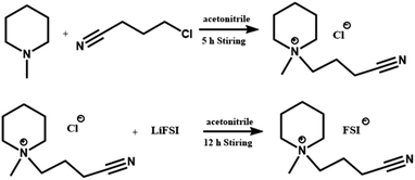 | ||
| Scheme 1 The synthesis of N-butyronitrile-N-methylpiperidinium bis(fluorosulfonyl)imide (PP1,CNFSI). | ||
The electrolyte composed of 1 M LiPF6 in the mixed solvent of DMC and EC (volume ratio 1![[thin space (1/6-em)]](https://www.rsc.org/images/entities/char_2009.gif) :
:![[thin space (1/6-em)]](https://www.rsc.org/images/entities/char_2009.gif) 1) was called blank electrolyte.
1) was called blank electrolyte.
The different electrolytes were prepared by adding various concentrations PP1,CNFSI in blank electrolyte. The moisture content of the final electrolytes were less than 10 ppm according to Karl Fischer titration. The above processes were carried out in glove box (O2 < 1 ppm, H2O < 1 ppm).
2.3 Theoretical calculation
The quantum chemistry calculation is a method to study chemical process through the theory of quantum mechanics. Gaussian 09 package was used to calculate the quantum chemistry by using density functional theory (DFT).37–39 Theoretical calculation was conducted by using the 6-311 + G (d,p) basis set at the RB3LYP. The molecular and ionic structures of the solution were optimized and calculated. The structures were optimized by using the polarization continuum model (PCM). The dielectric constant value of solvent was 46.1.2.4 Electrodes preparation and battery assembly
The cathode materials composed of 90 wt% LNMO, 5 wt% PVDF, and 5 wt% acetylene black into NMP were coated on Al foil and dried at 100 °C under vacuum. The average active material loading was approximately 3.6 mg cm−2. The CR2032 coin cells were assembled in an Ar-filled glove box (O2 < 1 ppm, H2O < 1 ppm).2.5 Physical properties measurements
The ionic conductivities at room temperature were measured by DDS-307 conductivity meter (Shanghai Lei Magnetic Instrument Factory). A platinum black electrode was used and the electrode constant was 1.0. The conductivities of the same concentration were tested three times and then the average value was taken. Thermogravimetric analysis (TGA) test was conducted by a TGA analyzer (NETZSCHSTA409PC). The cotton was dipped in blank electrolyte, ionic liquid electrolyte and pure ionic liquid, respectively. After the electrolytes were ignited for 3 s, the flame was removed. The flammability of electrolyte was evaluated.2.6 Electrochemical tests
The first charge–discharge performance and the cycle performance at 0.2 C of Li/LNMO battery were carried out between 3.0 and 5.0 V with a CT2001A test system (Land Instruments, Wuhan). Linear Sweep Voltammetry (LSV) was carried out in a three-electrode system with the Pt working electrode, the lithium metal as reference and counter electrode in 3.0–5.5 V. The scanning rate is 0.1 mV s−1. The cyclic voltammetry (CV) was carried out in 3.0–5.0 V with a scan rate of 0.1 mV s−1. Resistance associated with the electrode/electrolyte interface was evaluated using electrochemical impedance spectroscopy (EIS) during cycling. It was performed at 100 kHz to 0.1 Hz with the amplitude of 0.1 mV. The tests of LSV, CV and EIS were carried out on a CHI660D electrochemistry workstation (Chenhua, China).2.7 Material characterizations
The LNMO cathodes were carefully removed from the battery and were rinsed with DMC in glove box. The cathodes were dried at 80 °C under vacuum for 10 h. The morphology of the LNMO cathode was researched by scanning electron microscopy (SEM, JSM-6701F) and transmission electron microscopy (TEM, JELO JEM-2100). X-ray photoelectron spectroscopy (XPS) was employed to identify surface element composition of the cycled cathode by ESCALAB 250Xi X-ray photoelectron spectroscopy.3. Results and discussion
3.1 The structural characterization of IL
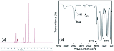
The IL was confirmed by 1H NMR (Fig. 1a). 1H NMR (400 MHz, CDCl3): δ 1.702–1.738 (t, 2H, CH2), 1.912 (s, 4H, CH2), 2.155 (s, 2H, CH2), 2.549–2.561 (s, 2H, CH2), 3.046 (s, 3H, CH3N), 3.348 (s, 6H, CH2). The chemical structure of IL was also confirmed by FT-IR spectrometry (Fig. 1b). The resonance peaks at 1103 cm−1 and 1176 cm−1 are associated with S–F and SO2 from the FSI anion. Piperidine ring can be identified by the spectra features at 2964 cm−1 (C–H stretching) and at 2882 cm−1 (C–N stretching). The resonance peaks at 2251 cm−1 can be ascribed to –CN. These results confirm that PP1,CNFSI was successfully synthesized. The conductivity and electrochemical window of PP1,CNFSI and the commercial ILs are compared, the results are shown in Table 1. PP1,CNFSI has a quite wide potential window (5 V), and a high ionic conductivity (6.8 mS cm−1 at 25 °C), indicating it is suitable for the electrolyte additive.| Ionic liquid | Conductivity (mS cm−1 25 °C) | Electrochemical window (V) |
|---|---|---|
| PP1,CNFSI | 6.8 | 5.0 |
| N-Methyl-N-propylpiperidinium FSI (PP1,3FSI) | 3.7 | 4.9 |
| N-Methyl-N-propylpyrrolidinium FSI (Py13FSI) | 8.2 | 4.8 |
| 1-Ethyl-3-methylimidazolium TFSI (EMIMTFSI) | 7.5 | 4.3 |
| 1-Butyl-3-methylimidazolium hexafluorophosphate (EMIMPF6) | 5.2 | 4.5 |
| 1-Butyl-3-methylimidazolium TFSI (BMIMTFSI) | 2.6 | 4.4 |
3.2 The analysis of theoretical calculations
The calculations were conducted to gain better theoretical insights into the electrochemical behavior of the electrolyte and PP1,CNFSI used in LIBs. The results for highest occupied molecular orbital (HOMO) and lowest unoccupied molecular orbital (LUMO) energies of DMC, EC, and PP1,CNFSI are summarized in Table 2. Obviously, the calculation reveals that the HOMO value of the PP1,CNFSI is higher than EC and DMC, suggesting the oxidation of PP1,CNFSI is more easy. Therefore, PP1,CNFSI has a lower oxidation potential than the EC and DMC. Moreover, the LUMO value of the PP1,CNFSI is lower than EC and DMC, so PP1,CNFSI is more susceptible to be reduced.40| Electrolyte | HOMO/eV | LUMO/eV |
|---|---|---|
| EC | −8.4669 | −0.2838 |
| DMC | −8.1591 | 0.1298 |
| PP1,CNFSI | −7.5468 | −0.8397 |
3.3 Physicochemical properties of electrolyte
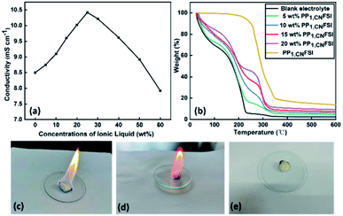
Ionic conductivity is an important parameter for the performance of LIBs with organic solvent as electrolyte solution, because of its important effect on the internal resistance. Compared to blank electrolyte, the ionic conductivity increases with PP1,CNFSI addition, and it reaches to a maximum value when the content of PP1,CNFSI is 25 wt% (Fig. 2a). The increased conductivity was related to the increase of the ions concentration in the electrolyte. The conductivity began to decrease when the content of PP1,CNFSI continues to increase, which was due to the increase of electrolyte viscosity and the decrease of free ions.Fig. 2b shows the TGA curves of the electrolytes. Thermal stability is an essential property for battery safety. For blank electrolyte, a remarkable weigh loss was observed from 25 to 230 °C and the electrolyte weight retention is only 6.7%, which was assigned to the evaporation and decomposition of carbonate solvent. While for the PP1,CNFSI no significant weight loss was observed until 230 °C, which illustrates PP1,CNFSI is a substance with high thermal stability. For the electrolytes of PP1,CNFSI addition, the weight retentions of 5 wt%, 10 wt%, 15 wt%, 20 wt% PP1,CNFSI are 18.5%, 32%, 40.8%, 47.3% at 230 °C. The result illustrates that the thermal stability of electrolyte is improved with PP1,CNFSI addition, which is expected to become an important choice for electrolyte system.
The non-flammability property of the electrolyte can greatly improve the safety of LIBs. The flammability tests for the blank electrolyte, the electrolyte with PP1,CNFSI addition and pure PP1,CNFSI have been performed to study the combustion performance. It is observed in Fig. 2c that the blank electrolyte immediately catches fire and the combustion flame continues to increase because of the combustion of carbonate solvents and the thermal decomposition of lithium salts. However, it is not easy for the electrolyte with PP1,CNFSI to catch fire (Fig. 2d), whereas pure PP1,CNFSI can't be ignited (Fig. 2e). It indicates that the addition of IL greatly improves the non-flammability of the electrolyte, and therefore improves the safety of the battery.
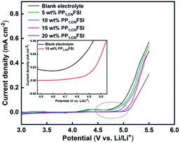
The electrochemical stability of electrolytes was evaluated by LSV. The oxidative current of blank electrolyte generates slowly at approximately 4.2 V, and then it increases when the potential is 4.7 V, which indicates that the blank electrolyte suffers from severe oxidative decomposition (Fig. 3).41 While the electrolytes containing PP1,CNFSI have lower oxidation current before 5.0 V, and the oxidation potential is shifted to the higher position with the increase of PP1,CNFSI addition. The result indicates that PP1,CNFSI acts as a significant inhibitory effect on the electrolyte decomposition at high voltage, indicating that the electrolytes with PP1,CNFSI addition have better electrochemical stability.42,43
3.4 Electrochemical performance of Li/LNMO cells
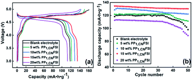
After checking the stability of electrolyte, the first charge–discharge property of Li/LNMO cells was investigated with the electrolytes containing different contents of PP1, CNFSI at 0.2 C (Fig. 4a). The first charge capacity of the cell with blank electrolyte is 160.6 mAh g−1, which is larger than the theoretical capacity of 147 mAh g−1 for LNMO, while the discharge capacity is only 119.21 mAh g−1, suggesting a serious capacity loss. The overcharge phenomenon and loss of irreversible capacity are assigned to decomposition of organic solvent in blank electrolyte.29 Interestingly, the overcharge and the loss of irreversible capacity can be suppressed with appropriate content of PP1,CNFSI addition. The first charge capacity with 5 wt%, 10 wt%, 15 wt%, and 20 wt% PP1,CNFSI addition are 150.5 mAh g−1, 142.2 mAh g−1, 153.7 mAh g−1, 140.6 mAh g−1 respectively, slightly higher or even comparable with that of theoretical capacity of 147 mAh g−1. The discharge capacity stably increases within 15 wt% PP1,CNFSI addition, with 121.8 mAh g−1 for 5 wt%, 128.6 mAh g−1 for 10 wt% and 134.5 mAh g−1 for 15 wt% IL, while it drops to 112.6 mAh g−1 for 20 wt% PP1,CNFSI addition due to the increased viscosity. The positive effect of PP1,CNFSI addition is further confirmed by analysis the capacity increment above 4.8 V. The cell with blank electrolyte shows an increment of 40 mAh g−1 above 4.8 V possibly induced by heavy organic solvent decomposition, while no obvious capacity above 4.8 V is found with PP1,CNFSI addition.The cycle performances of Li/LNMO cells cycled in different electrolytes were shown in Fig. 4b. The cells with 5 wt%, 10 wt%, and 15 wt% PP1,CNFSI addition exhibit higher initial discharge capacities than the cell with blank electrolyte. The discharge capacities retentions increase with the increased PP1,CNFSI addition within 15% (91.3% for 5 wt%, 93.8% for 10 wt%, 96.8% for 15 wt%, respectively) after 50 cycles, which are higher than that with blank electrolyte (82.8%). While the discharge capacity retention with 20 wt% PP1,CNFSI has shown more drop compared to blank electrolyte, which is possibly resulted from the high viscosity inducing limitation of Li+ migration in the electrolyte. Therefore, we believe that the addition of IL with suitable amount significantly increases the cycle performance.
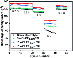
The dynamics and stability of the electrode can be evaluated by rate performance. Thus, the rate performance at various rates (0.2 C, 0.5 C, 1 C, 5 C) was carried out in various electrolytes (Fig. 5). The cell with 20 wt% PP1,CNFSI addition was excluded because of its low charge and discharge capacity. The discharge capacity of the cell decreases with the rate increases. The discharge capacity of the cell with PP1,CNFSI is higher than that of the cell with blank electrolyte at all rates. The cells with the 5 wt%, 10 wt%, 15 wt% PP1,CNFSI exhibit excellent rate performance with average discharge capacities of 122 mAh g−1, 130.3 mAh g−1, 134.1 mAh g−1 at 0.2 C, and the discharge capacities are 72.3 mAh g−1, 79.3 mAh g−1, 87.2 mAh g−1 at 5 C. However, the average discharge capacities of blank electrolyte are 120.6 mAh g−1 and 58 mAh g−1 at 0.2 C and 5 C. In addition, when returned to 0.2 C, the discharge capacities with 5 wt%, 10 wt%, 15 wt% PP1,CNFSI maintain at 121 mAh g−1, 126 mAh g−1, 127.8 mAh g−1, respectively, while blank electrolyte could not recover well (only 118 mAh g−1). Apparently, PP1,CNFSI as additive can significantly improve the rate performance of LNMO electrode.
The cells with 10 wt%, 15 wt% PP1,CNFSI addition were further investigated because of better capacity retention and rate performance. There are two couples of redox peaks on each curve (Fig. 6). The oxidation peaks at around 4.0 V are assigned to the reaction of Mn3+/Mn4+, the reduction peaks appear around 3.9 V, corresponding to the reaction of Mn4+/Mn3+. For the cell with blank electrolyte, the oxidation peaks around 4.8 V and 4.9 V are attributed to the reactions of Ni2+/Ni3+ and Ni3+/Ni4+, which shift negatively by 25 mV and 13 mV with 10% and 15% PP1,CNFSI addition, respectively. As for the reduction, the peaks at around 4.4 V are assigned to the reaction of Ni4+/Ni2+ showing the positive shifts of 47 mV and 87 mV with 10 wt% and 15 wt% PP1,CNFSI addition. The redox voltage difference of the cells with 10 wt% (0.50 V) and 15 wt% (0.47 V) PP1,CNFSI are lower than the cell with blank electrolyte (0.57 V) suggesting that the LNMO with 15 wt% PP1,CNFSI has better reversibility and lower polarization.20 Meanwhile, the redox current values from electrolyte with 15 wt% PP1,CNFSI are higher than that from electrolyte with 10 wt% and no additive, indicating that the LNMO material with 15 wt% PP1,CNFSI has better structural integrity.29
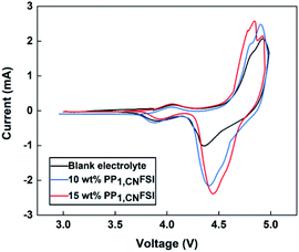 | ||
| Fig. 6 Cyclic voltammetry of Li/LNMO cells with electrolytes containing various contents of PP1,CNFSI additive after 50 cycles. | ||
To confirm the function of PP1,CNFSI, EIS measurement was performed to observe the impedance during cycling (Fig. 7a and b). The EIS equivalent circuit of the battery was shown in Fig. 7c, where Rs stands for the solution resistance and Rct stands for the resistance of charge transfer between cathode and electrolyte. The value of Rs is approximately 6 Ω for the two cells. The value of Rct for the cell with blank electrolyte before cycle is 35.16 Ω much lower than that of the cell with 15 wt% PP1,CNFSI (262.9 Ω), because the lower electrolyte viscosity can decrease the impedance before cycle. However, for the cell with blank electrolyte, the Rct value increases to 178.7 Ω after 5 cycles and further increases to 642.8 Ω after 50 cycles (Table 3). It indicates that the SEI film gradually thickens, which hinders the transport of Li+ on electrode/electrolyte interface.32 By contrast, the Rct value of cell with 15 wt% PP1,CNFSI decreases steadily to 153.9 Ω and 119.33 Ω after 5 and 50 cycles, respectively, indicating that film generation is relatively thinner and stabler. Therefore, the EIS results demonstrate that adding PP1,CNFSI can form a protective SEI film on the LNMO surface, which can reduce the battery resistance and promote the transfer of Li+.
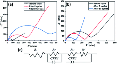 | ||
| Fig. 7 EIS spectra of Li/LNMO electrodes cycled in blank electrolyte (a), 15 wt% PP1,CNFSI electrolyte (b) and the equivalent circuit of the battery (c). | ||
| Sample | Blank electrolyte | with 15 wt% PP1,CNFSI | |
|---|---|---|---|
| Before cycle | Rct (Ω) | 35.16 | 262.9 |
| After 5 cycles | Rct (Ω) | 178.7 | 153.9 |
| After 50 cycles | Rct (Ω) | 642.8 | 119.33 |
3.5 Morphology and composition studies of LNMO
To further understand the influence of PP1,CNFSI on the stability of cathode material. SEM and TEM were applied to characterize the LNMO electrode after cycling (Fig. 8). The fresh LNMO cathode shows a complete and smooth spinel shape (Fig. 8a), consistent with previous reports.6,16 For the LNMO cathode with blank electrolyte after 50 cycles, the spinel shape is extremely irregular and the structure becomes rough (Fig. 8b), this is because the electrolyte is continuously decomposed and deposited on the electrode surface, or Mn3+ in the cathode is dissolved in electrolyte. Contrary to this, the image of the cathode with 15 wt% PP1,CNFSI maintains structure integrity in the Fig. 8c. It shows that the addition of PP1,CNFSI can decelerate the decomposition of electrolyte, and protects the structure of cathode material.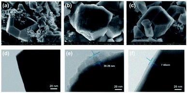 | ||
| Fig. 8 SEM and TEM images of fresh LNMO cathode (a), (d) and the cathode after 50 cycles with the blank electrolyte (b), (e) and with 15 wt% PP1,CNFSI (c), (f). | ||
To further characterize the surface of LNMO cathode, the fresh and cycled cathodes with and without PP1,CNFSI were analysized by TEM. The fresh cathode shows a very smooth and clean surface (Fig. 8d). The cycled cathode with blank electrolyte shows an uneven and thick SEI film, with a thickness of 38.28 nm (Fig. 8e). This is due to the products from Mn ion dissolution from the LNMO cathode and continuous oxidation reaction of the carbonate solvent, which result in serious capacity degradation of the battery.44 In contrast, the cycled cathode with PP1,CNFSI has a thinner and uniform SEI film on the surface (Fig. 8f), with a thickness of 7.45 nm. This film protects the cathode from structural damage.
To identify the composition of the LNMO cathode surface SEI film, the fresh and cycled cathodes with blank electrolyte and with 15 wt% PP1,CNFSI were analysized by XPS (Fig. 9). In the C 1s spectrum of a fresh cathode, three peaks at 284.6, 286.3, 290.9 eV appear, which belong to C–C, C–O and C–F in PVDF, respectively (Fig. 9a).17 For the cycled cathode, a new peak observed at 288.6 eV corresponds to C![[double bond, length as m-dash]](https://www.rsc.org/images/entities/char_e001.gif) O. The intensity of C–O increases, indicating deposition species formation by the decomposition of carbonate electrolyte. The intensity of the peaks of C–O and C
O. The intensity of C–O increases, indicating deposition species formation by the decomposition of carbonate electrolyte. The intensity of the peaks of C–O and C![[double bond, length as m-dash]](https://www.rsc.org/images/entities/char_e001.gif) O decreases with adding PP1,CNFSI, indicating that the addition of PP1,CNFSI can effectively inhibit the decomposition of organic solvents. The O 1s spectra of fresh LNMO cathode contains a strong and a weak peak (Fig. 9b) corresponding to the metal-O (529.8 eV) and C
O decreases with adding PP1,CNFSI, indicating that the addition of PP1,CNFSI can effectively inhibit the decomposition of organic solvents. The O 1s spectra of fresh LNMO cathode contains a strong and a weak peak (Fig. 9b) corresponding to the metal-O (529.8 eV) and C![[double bond, length as m-dash]](https://www.rsc.org/images/entities/char_e001.gif) O (531.6 eV) of Li2CO3.41 After cycling with blank electrolyte, a new peak observed at 533.1 eV corresponds to C–O,45 and the intensity of the peaks C–O and C
O (531.6 eV) of Li2CO3.41 After cycling with blank electrolyte, a new peak observed at 533.1 eV corresponds to C–O,45 and the intensity of the peaks C–O and C![[double bond, length as m-dash]](https://www.rsc.org/images/entities/char_e001.gif) O increases obviously implying the decomposition of organic solvents. As for the cathode with PP1,CNFSI addition, the intensity of the peak of C–O decreases, indicating suppression of the organic solvents decomposition. For F 1s spectra, only one peak can be observed located at 687.9 eV for the fresh cathode (Fig. 9c) corresponding to C–F in PVDF. For the cycled cathode, the peaks appear around 684.6 eV and 686.8 eV, corresponding to the LiF and LixPOyFz, which are obtained from the hydrolysis of LiPF6.46,47 The intensity of the peaks is weaker with PP1,CNFSI than without PP1,CNFSI, which also reflects that PP1,CNFSI can depress the formation of fluorine compounds. Analysis of the N 1s spectrum of the LNMO cathode cycled in PP1,CNFSI containing electrolyte shows two peaks (Fig. 9d), which are attributed to the FSI peak (399.7 eV) and piperidine-N peak (402.7 eV). The FSI and piperidine-N are the composition of the cathode protective SEI film, preventing further oxidation of the electrolyte.48
O increases obviously implying the decomposition of organic solvents. As for the cathode with PP1,CNFSI addition, the intensity of the peak of C–O decreases, indicating suppression of the organic solvents decomposition. For F 1s spectra, only one peak can be observed located at 687.9 eV for the fresh cathode (Fig. 9c) corresponding to C–F in PVDF. For the cycled cathode, the peaks appear around 684.6 eV and 686.8 eV, corresponding to the LiF and LixPOyFz, which are obtained from the hydrolysis of LiPF6.46,47 The intensity of the peaks is weaker with PP1,CNFSI than without PP1,CNFSI, which also reflects that PP1,CNFSI can depress the formation of fluorine compounds. Analysis of the N 1s spectrum of the LNMO cathode cycled in PP1,CNFSI containing electrolyte shows two peaks (Fig. 9d), which are attributed to the FSI peak (399.7 eV) and piperidine-N peak (402.7 eV). The FSI and piperidine-N are the composition of the cathode protective SEI film, preventing further oxidation of the electrolyte.48
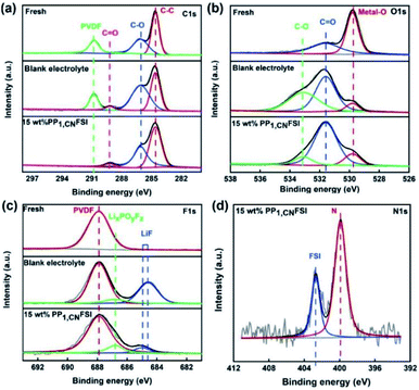 | ||
| Fig. 9 XPS spectra of fresh LNMO cathode and the cathodes cycled with blank electrolyte and 15 wt% PP1,CNFSI electrolyte after 50 cycles. C 1s (a), O 1s (b), F 1s (c), N 1s (d). | ||
4. Conclusion
A novel ionic liquid PP1,CNFSI has been synthesized and explored as electrolyte additive to supress decomposition of electrolyte, stabilizate cathode materials structure and improve electrochemical performance. The LSV result indicates that P1,CNFSI can improve the oxidation potential of the electrolyte and have better electrochemical stability at high voltage. The CV and EIS results demonstrate that PP1,CNFSI can reduce in electrochemical polarization and decrease the battery resistance through forming a protective SEI film on the LNMO surface. In addition, a stable and uniform SEI film on the surface of LNMO cathode surface with PP1,CNFSI addition was clearly characterized by SEM, TEM and XPS. This study provides reference for the design of high-voltage LIBs.Conflicts of interest
There are no conflicts to declare.Acknowledgements
Financial support from the Colleges and Universities in Hebei Province Science and Technology Research Project (ZD2015118) is gratefully acknowledged.References
- Q. Zhang, D. Zhu, X. Li and Y. Zhang, RSC Adv., 2020, 10, 43312–43318 RSC.
- T. Autthawong, Y. Chimupala, M. Haruta, H. Kurata, T. Kiyomura, A.-s. Yu, T. Chairuangsri and T. Sarakonsri, RSC Adv., 2020, 10, 43811–43824 RSC.
- M. Wang, T. Chen, T. Liao, X. Zhang, B. Zhu, H. Tang and C. Dai, RSC Adv., 2021, 11, 1200–1221 RSC.
- H. B. Lin, W. Z. Huang, H. B. Rong, S. W. Mai, J. N. Hu, L. D. Xing, M. Q. Xu and W. S. Li, J. Solid State Electrochem., 2015, 19, 1123–1132 CrossRef CAS.
- H. Bouayad, Z. Wang, N. Dupré, R. Dedryvère, D. Foix, S. Franger, J. F. Martin, L. Boutafa, S. Patoux, D. Gonbeau and D. Guyomard, J. Phys. Chem. C, 2014, 118, 4634–4648 CrossRef CAS.
- X. Zhu, X. Li, Y. Zhu, S. Jin, Y. Wang and Y. Qian, Electrochim. Acta, 2014, 121, 253–257 CrossRef CAS.
- T. A. Arunkumar and A. Manthiram, Electrochim. Acta, 2005, 50, 5568–5572 CrossRef CAS.
- M. Kuenzel, G.-T. Kim, M. Zarrabeitia, S. D. Lin, A. R. Schuer, D. Geiger, U. Kaiser, D. Bresser and S. Passerini, Mater. Today, 2020, 39, 127–136 CrossRef CAS.
- Y. Xue, L.-L. Zheng, J. Wang, J.-G. Zhou, F.-D. Yu, G.-J. Zhou and Z.-B. Wang, ACS Appl. Energy Mater., 2019, 2, 2982–2989 CrossRef CAS.
- X. Cao, X. He, J. Wang, H. Liu, S. Roser, B. R. Rad, M. Evertz, B. Streipert, J. Li, R. Wagner, M. Winter and I. Cekic-Laskovic, ACS Appl. Mater. Interfaces, 2016, 8, 25971–25978 CrossRef CAS PubMed.
- D. Xu, F. Yang, Z. Liu, X. Zeng, Y. Deng, Y. Zheng, H. Lou and S. Liao, Ionics, 2020, 26, 3777–3783 CrossRef CAS.
- L. Hu, Z. Zhang and K. Amine, Electrochem. Commun., 2013, 35, 76–79 CrossRef CAS.
- Y.-R. Zhu, T.-F. Yi, X.-Y. Li, Y. Xie and S. Luo, Mater. Lett., 2019, 239, 56–58 CrossRef CAS.
- S.-Y. Ha, J.-G. Han, Y.-M. Song, M.-J. Chun, S.-I. Han, W.-C. Shin and N.-S. Choi, Electrochim. Acta, 2013, 104, 170–177 CrossRef CAS.
- D. Wang, C. Li, C. Ma, F. Liang, L. Dong, C. Zhu and Y. Gao, J. Power Sources, 2019, 434, 226747 CrossRef CAS.
- X. Wang, W. Xue, K. Hu, Y. Li, Y. Li and R. Huang, ACS Appl. Energy Mater., 2018, 1, 5347–5354 CAS.
- J. Chen, Y. Gao, C. Li, H. Zhang, J. Liu and Q. Zhang, Electrochim. Acta, 2015, 178, 127–133 CrossRef CAS.
- G. B. Appetecchi, M. Montanino and S. Passerini, in Ionic Liquids: Science and Applications, 2012, pp. 67–128, DOI:10.1021/bk-2012-1117.ch004.
- G. Yan, X. Li, Z. Wang, H. Guo and X. Xiong, J. Power Sources, 2014, 263, 231–238 CrossRef CAS.
- L. Xue, K. Ueno, S.-Y. Lee and C. A. Angell, J. Power Sources, 2014, 262, 123–128 CrossRef CAS.
- W. Zhang, S. Yang, S. T. Bai, L. H. Zhang, Y. Zhang and F. Yu, ChemCatChem, 2021, 13, 1–7 CrossRef.
- W. Huang, L. Xing, R. Zhang, X. Wang and W. Li, J. Power Sources, 2015, 293, 71–77 CrossRef CAS.
- D. Meghnani, H. Gupta, S. K. Singh, N. Srivastava, R. Mishra, R. K. Tiwari, A. Patel, A. Tiwari and R. K. Singh, Ionics, 2020, 26, 4835–4851 CrossRef CAS.
- X. Gao, Q. Qu, G. Zhu, T. Gao, F. Qian, Q. Shi and H. Zheng, RSC Adv., 2017, 7, 50135–50142 RSC.
- G. Wang, S. Shen, S. Fang, D. Luo, L. Yang and S.-i. Hirano, RSC Adv., 2016, 6, 71489–71495 RSC.
- S. Maiti, A. Pramanik and S. Mahanty, RSC Adv., 2015, 5, 41617–41626 RSC.
- H. Qi, Y. Ren, S. Guo, Y. Wang, S. Li, Y. Hu and F. Yan, ACS Appl. Mater. Interfaces, 2020, 12, 591–600 CrossRef CAS PubMed.
- A. Tsurumaki, M. Agostini, R. Poiana, L. Lombardo, E. Lufrano, C. Simari, A. Matic, I. Nicotera, S. Panero and M. A. Navarra, Electrochim. Acta, 2019, 316, 1–7 CrossRef CAS.
- L. Dong, F. Liang, D. Wang, C. Zhu, J. Liu, D. Gui and C. Li, Electrochim. Acta, 2018, 270, 426–433 CrossRef CAS.
- W. Weng, Z. Zhang, J. A. Schlueter and K. Amine, Electrochim. Acta, 2013, 92, 392–396 CrossRef CAS.
- T. Yim, M.-S. Kwon, J. Mun and K. T. Lee, Isr. J. Chem., 2015, 55, 586–598 CrossRef CAS.
- W. Zhang, Y. Wang, X. Lan and Y. Huo, Res. Chem. Intermed., 2020, 46, 3007–3023 CrossRef CAS.
- M. Ishikawa, T. Sugimoto, M. Kikuta, E. Ishiko and M. Kono, J. Power Sources, 2006, 162, 658–662 CrossRef CAS.
- N. Madria, T. A. Arunkumar, N. G. Nair, A. Vadapalli, Y.-W. Huang, S. C. Jones and V. P. Reddy, J. Power Sources, 2013, 234, 277–284 CrossRef CAS.
- A. Lewandowski and A. Świderska-Mocek, J. Power Sources, 2009, 194, 601–609 CrossRef CAS.
- S. F. Lux, M. Schmuck, S. Jeong, S. Passerini, M. Winter and A. Balducci, Int. J. Energy Res., 2010, 34, 97–106 CrossRef CAS.
- K. Angenendt and P. Johansson, J. Phys. Chem. B, 2011, 115, 7808–7813 CrossRef CAS PubMed.
- J. C. Lassègues, J. Grondin, R. Holomb and P. Johansson, J. Raman Spectrosc., 2007, 38, 551–558 CrossRef.
- K. Yue, C. Zhai, S. Gu, Y. He, J. Yeo and G. Zhou, Electrochim. Acta, 2021, 368, 137535 CrossRef CAS.
- K. Chatterjee, A. D. Pathak, A. Lakma, C. S. Sharma, K. K. Sahu and A. K. Singh, Sci. Rep., 2020, 10, 9606 CrossRef PubMed.
- L. Wang, Y. Ma, Q. Li, Z. Zhou, X. Cheng, P. Zuo, C. Du, Y. Gao and G. Yin, J. Power Sources, 2017, 361, 227–236 CrossRef CAS.
- S. Han, H. Zhang, C. Fan, W. Fan and L. Yu, Solid State Ionics, 2019, 337, 63–69 CrossRef CAS.
- L. Wang, Y. Ma, Y. Qu, X. Cheng, P. Zuo, C. Du, Y. Gao and G. Yin, Electrochim. Acta, 2016, 191, 8–15 CrossRef CAS.
- Y. Zhu, X. Luo, H. Zhi, Y. Liao, L. Xing, M. Xu, X. Liu, K. Xu and W. Li, J. Mater. Chem. A, 2018, 6, 10990–11004 RSC.
- T. Huang, X. Zheng, Y. Pan, Q. Li and M. Wu, ACS Appl. Mater. Interfaces, 2019, 11, 26872–26879 CrossRef CAS PubMed.
- H. Duncan, D. Duguay, Y. Abu-Lebdeh and I. J. Davidson, J. Electrochem. Soc., 2011, 158, A537–A545 CrossRef CAS.
- J. Liu and A. Manthiram, J. Electrochem. Soc., 2009, 156, A66–A72 CrossRef CAS.
- F. Liang, J. Yu, J. Chen, D. Wang, C. Lin, C. Zhu, M. Wang, L. Dong and C. Li, Electrochim. Acta, 2018, 283, 111–120 CrossRef CAS.
| This journal is © The Royal Society of Chemistry 2021 |

